

Page 1
Operating Instructions and Parts Manual
This .pdf document is bookmarked
12”x20” Semi-Automatic Variable-Speed Mitering Band Saw
Models HBS-1220MSA, HBS-1220MSAH
JET
427 New Sanford Road
LaVergne, Tennessee 37086 Part No. M-424476
Ph.: 800-274-6848 Edition 3 04/2019
www.jettools.com Copyright © 2018 JET
1
Page 2

1.0 IMPORTANT SAFETY
INSTRUCTIONS
WARNING – To reduce risk of injury:
1. Read and understand the entire owner's
manual before attempting assembly or
operation.
2. Read and understand the warnings posted on
the machine and in this manual. Failure to
comply with all of these warnings may cause
serious injury.
3. Replace warning labels if they become
obscured or removed.
4. This band saw is designed and intended for use
by properly trained and experienced personnel
only. If you are not familiar with the proper and
safe operation of a band saw, do not use until
proper training and knowledge have been
obtained.
5. Do not use this band saw for other than its
intended use. If used for other purposes, JET
disclaims any real or implied warranty and holds
itself harmless from any injury that may result
from that use.
6. Always wear leather gloves when handling saw
blades. The operator shall not wear gloves
when operating the machine.
7. Machinery must be anchored to the floor.
8. Secure work. Use clamps or a vise to hold work,
when practical. It is safer than using your hands
and it frees both hands to operate the machine.
9. All doors shall be closed, all panels replaced,
and other safety guards in place prior to the
machine being started or operated.
10. Be sure that the blade is not in contact with the
workpiece when the motor is started. The motor
shall be started and you should allow the saw to
come up to full speed before bringing the saw
blade into contact with the workpiece.
11. Keep hands away from the blade area.
12. Remove any cut off piece carefully while
keeping your hands free of the blade area.
13. Saw must be stopped and electrical supply
must be cut off before any blade replacement or
adjustment of blade support mechanism is
done, or before any attempt is made to change
the drive belts or before any periodic service or
maintenance is performed on the saw.
14. Remove loose items and unnecessary
workpieces from area before starting machine.
15. Bring adjustable saw guides and guards as
close as possible to the workpiece.
16. Always wear protective eye wear when
operating, servicing, or adjusting machinery.
Eyewear shall be impact resistant, protective
safety glasses with side shields complying with
ANSI Z87.1 specifications. Use of eye wear
which does not comply with ANSI Z87.1
specifications could result in severe injury from
breakage of eye protection.
17. Wear proper apparel. No loose clothing or
jewelry which can get caught in moving parts.
Confine long hair.
18. Anti-skid floor strips, nonslip footwear and
safety shoes are recommended.
19. Wear hearing protection (plugs or muffs) if
sound reaches unsafe levels.
20. The workpiece, or part being sawn, must be
securely clamped before the saw blade enters
the workpiece.
21. Remove cut off pieces carefully, keeping hands
away from saw blade.
22. Saw must be stopped and electrical supply cut
off or machine unplugged before reaching into
cutting area.
23. Avoid contact with coolant, especially guarding
your eyes.
24. Make certain the switch is in the OFF position
before connecting the machine to the power
supply.
25. This saw must be grounded in accordance with
the National Electrical Code and local codes
and ordinances. This work should be done by a
qualified electrician. The saw must be grounded
to protect the user from electrical shock.
Caution: For circuits which are far away from
the electrical service box, the wire size must be
increased in order to deliver ample voltage to
the motor. To minimize power losses and to
prevent motor overheating and burnout, the use
of wire sizes for branch circuits or electrical
extension cords according to the following table
is recommended.
AWG (American Wire
Conductor
length
0-50 ft. # 14
50-500 ft. # 14
Over 100 ft. # 12
Gauge) Number
240 volt lines
Table 1
2
Page 3

26. Disconnect electrical power before servicing.
Whenever changing accessories or general
maintenance is done on the machine, electrical
power to the machine must be disconnected
before work is done.
27. Remove adjusting keys and wrenches. Form a
habit of checking to see that keys and adjusting
wrenches are removed from the machine
before turning it on.
28. Keep safety guards in place at all times when
the machine is in use. If removed for
maintenance purposes, use extreme caution
and replace the guards immediately after
completion of maintenance.
29. Check damaged parts. Before further use of the
machine, a guard or other part that is damaged
should be carefully checked to determine that it
will operate properly and perform its intended
function. Check for alignment of moving parts,
binding of moving parts, breakage of parts,
mounting and any other conditions that may
affect its operation. A guard or other part that is
damaged should be properly repaired or
replaced.
30. Maintain all machine tools with care. Follow all
maintenance instructions for lubricating and the
changing of accessories.
31. No attempt shall be made to modify or have
makeshift repairs done to the machine. This not
only voids the warranty but also renders the
machine unsafe.
32. Keep work area clean. Cluttered areas invite
accidents. Keep the floor around the machine
clean and free of scrap material, oil and grease.
33. Keep visitors a safe distance from the work
area. Keep children away.
34. Make your workshop child proof with padlocks,
master switches or by removing starter keys.
35. Give your work undivided attention. Looking
around, carrying on a conversation and “horseplay” are careless acts that can result in serious
injury.
36. Maintain a balanced stance at all times so that
you do not fall into the blade or other moving
parts. Do not overreach or use excessive force
to perform any machine operation.
37. Use the right tool at the correct speed and feed
rate. Do not force a tool or attachment to do a
job for which it was not designed. The right tool
will do the job better and more safely.
38. Use only recommended accessories; improper
accessories may be hazardous.
39. Keep saw blades sharp and clean for the best
and safest performance.
40. Turn off the machine before cleaning. Use a
brush or vacuum to remove chips or debris —
do not use bare hands. Never brush away chips
while machine is in operation.
41. Do not stand on the machine. Serious injury
could occur if the machine tips over.
42. Never leave the machine running unattended.
Turn the power off and do not leave the
machine until it comes to a complete stop.
43. Avoid dangerous working environments. Do not
use stationary machine tools in wet or damp
locations. Keep work areas clean and well lit.
WARNING: This product can expose you to
chemicals including cadmium and DEHP which
are known to the State of California to cause
cancer and birth defects or other reproductive
harm. For more information go to http://www.
p65warnings.ca.gov.
WARNING: Some dust, fumes and gases
created by power sanding, sawing, grinding,
drilling, welding and other construction activities
contain chemicals known to the State of
California to cause cancer and birth defects or
other reproductive harm. Some examples of
these chemicals are:
lead from lead based paint
crystalline silica from bricks, cement and
other masonry products
arsenic and chromium from chemically
treated lumber
Your risk of exposure varies, depending on how
often you do this type of work. To reduce your
exposure to these chemicals, work in a wellventilated area and work with approved safety
equipment, such as dust masks that are
specifically designed to filter out microscopic
particles. For more information go to
http://www.p65warnings.ca.gov/ and http://www.
p65warnings.ca.gov/wood.
SAVE THESE INSTRUCTIONS
Familiarize yourself with the following safety notices used in this manual:
This means that if precautions are
not heeded, it may result in minor injury and/or
possible machine damage.
not heeded, it may result in serious, or possibly even
fatal, injury.
3
This means that if precautions are
Page 4

2.0 Table of contents
Section Page
1.0 IMPORTANT SAFETY INSTRUCTIONS ....................................................................................................... 2
2.0 Table of contents ............................................................................................................................................ 4
3.0 Machine introduction ...................................................................................................................................... 5
4.0 About this manual .......................................................................................................................................... 5
5.0 Specifications ................................................................................................................................................. 6
6.0 Setup and assembly ....................................................................................................................................... 7
6.1 Shipping contents ....................................................................................................................................... 7
6.2 Tools required for assembly ....................................................................................................................... 7
6.3 Uncrating and spotting ............................................................................................................................... 7
6.4 Assembly .................................................................................................................................................... 7
6.5 Lubrication .................................................................................................................................................. 7
7.0 Electrical connections .................................................................................................................................... 8
7.1 Voltage conversion ..................................................................................................................................... 8
8.0 Adjustments ................................................................................................................................................... 8
8.1 Removing and installing blade ................................................................................................................... 8
8.2 Blade tension .............................................................................................................................................. 9
8.3 Blade tracking ............................................................................................................................................. 9
8.4 Blade guide bracket adjustment ................................................................................................................. 9
8.5 Blade guide bearing adjustment ............................................................................................................... 10
8.6 Test cutting to verify adjustment ............................................................................................................... 10
8.7 Changing blade speed ............................................................................................................................. 11
8.8 Broken blade safety device ...................................................................................................................... 11
8.9 Vise adjustments ...................................................................................................................................... 11
8.10 Adjusting work stop ................................................................................................................................ 12
8.11 Limit switch adjustment .......................................................................................................................... 12
8.12 Miter angle adjustment ........................................................................................................................... 12
9.0 Operating controls ........................................................................................................................................ 13
10.0 Operation ................................................................................................................................................... 13
10.1 Manual mode .......................................................................................................................................... 13
10.2 Automatic mode ..................................................................................................................................... 13
10.3 Blade selection ....................................................................................................................................... 14
10.4 Blade break-in procedure ....................................................................................................................... 14
10.5 Evaluating cutting efficiency ................................................................................................................... 14
11.0 User-maintenance ...................................................................................................................................... 14
11.1 Lubrication .............................................................................................................................................. 15
11.2 Additional servicing ................................................................................................................................ 16
11.3 Lubrication schedule .............................................................................................................................. 16
12.0 Blade speed recommendations .................................................................................................................. 17
13.0 Troubleshooting HBS-1220MSA/MSAH ..................................................................................................... 17
14.0 Replacement Parts ..................................................................................................................................... 18
14.1.1 HBS-1220MSA/MSAH Base Assembly – Exploded View ................................................................... 19
14.1.2 HBS-1220MSA/MSAH Oil Pump Assembly – Exploded View ............................................................ 20
14.1.3 HBS-1220MSA/MSAH Base Assembly – Parts List ............................................................................ 21
14.2.1 HBS-1220MSA/MSAH Bow Assembly – Exploded View .................................................................... 24
14.2.2 HBS-1220MSA/MSAH Bow Assembly – Parts List ............................................................................. 25
14.3.1 HBS-1220MSA/MSAH Control Box Assembly – Exploded View ........................................................ 28
14.3.2 HBS-1220MSA/MSAH Control Box Assembly – Parts List ................................................................. 29
14.4.1 HBS-1220MSA/MSAH Electrical Box Assembly – Exploded View ..................................................... 30
14.4.2 HBS-1220MSA/MSAH Electrical Box Assembly – Parts List .............................................................. 30
15.0 Electrical Connections ................................................................................................................................ 31
15.1.1 HBS-1220MSA wiring diagram ............................................................................................................ 31
15.1.2 HBS-1220MSA wiring diagram (cont.) ................................................................................................ 32
15.1.3 HBS-1220MSA electrical panel diagram ............................................................................................. 32
15.2.1 HBS-1220MSAH wiring diagram ......................................................................................................... 33
15.2.2 HBS-1220MSAH wiring diagram (cont.) .............................................................................................. 34
15.2.3 HBS-1220MSAH electrical panel diagram .......................................................................................... 35
15.3.1 HBS-1220MSA/MSAH voltage conversion diagrams .......................................................................... 35
16.0 Warranty and service ................................................................................................................................. 36
4
Page 5

3.0 Machine introduction
The JET HBS-1220MSA series Mitering Band Saws incorporate a number of design features and innovations to
make these saws a powerful and productive addition to machine shops, maintenance shops, tool rooms, and
fabrication and welding shops.
The swivel control panel allows the operator access to all machine controls from either side of machine. The 6point contact blade guide assemblies ensure greater accuracy and longer blade life. The semi-automatic cycle
enables the operator to initiate these steps from the control panel: coolant flow, blade start, bow down, rate of
descent, blade stop, bow up. Additionally, the MSAH model allows control panel operation of the hydraulic vise.
This highly versatile band saw is a proven time saver, offering optimal sawing performance.
Mail the provided registration card, or register your product online -
http://www.jettools.com/us/en/service-and-support/warranty/registration/
4.0 About this manual
This manual is provided by JET, covering the safe operation and maintenance procedures for a JET Model HBS1220MSA and HBS-1220MSAH Horizontal Band Saw. This manual contains instructions on installation, safety
precautions, general operating procedures, maintenance instructions and parts breakdown. Your machine has
been designed and constructed to provide consistent, long-term operation if used in accordance with the
instructions set forth in this document.
If there are questions or comments, please contact your local supplier or JET. JET can also be reached at our
web site: www.jettools.com.
Retain this manual for future reference. If the machine transfers ownership, the manual should accompany it.
Read and understand the entire contents of this manual before attempting assembly or
operation! Failure to comply may cause serious injury!
The specifications in this manual were current at time of publication, but because of our policy of continuous
improvement, JET reserves the right to change specifications at any time and without prior notice, without incurring
obligations.
5
Page 6

5.0 Specifications
Table 2
Stock number
Model number HBS-1220MSA HBS-1220MSAH
Motor and Electricals
Main motor type TEFC induction
Horsepower 3 HP (2.25 kW)
Phase 3 PH
Voltage 230/460 V (prewired 230 V) 1
Cycle 60 Hz
Listed FLA (full load amps) 8.5/4.2 A
Motor speed 1720 RPM
On/off switch Magnetic
Power transfer Drive belt with variable speed pulley
Power cable and plug
Recommended circuit size 2 15 A
Sound emission 3 75 dB
Hydraulic motor 1/2 HP (0.37 kW), 3PH, 230/460V, 60Hz, 1.91/0.96 A
Vise operation manual hydraulic
Coolant pump 1/8 HP (0.09 kW), 3PH, 230/460V, 60Hz, 0.2/0.1 A
Capacities
Round
Square (WxH)
Rectangle (WxH)
90 deg. 300 mm (11-13/16 in.)
45 deg. 285 mm (11-7/32 in.)
90 deg. 300 x 300 mm (11-13/16 x 11-13/16 in.)
45 deg. 285 x 285 mm (11-7/32 x 11-7/32 in.)
90 deg.
45 deg. 285 x 320 mm (11-7/32 x 12-9/16 in.)
Maximum jaw opening 500 mm (19-5/8 in.)
Blade size (WxTxL) 27 x 0.95 x 3960 mm (1 x 0.037 x 156 in.)
Blade wheel size (Dia. x W) Ø434 x 30 mm (17-3/32 x 1-3/16 in.)
Blade speed Variable, 90-370 SFPM
Gearbox 850 mL (1/4 gal.)
Hydraulic tank 1.5L (3/8 gal.)
Cutting fluid/coolant tank 39.9 L (10-1/2 gal.)
Main materials
Stand Steel
Bow Cast iron and steel
Blade wheels Cast iron
Bed Cast iron
Vise jaws Cast iron
General dimensions
Height of bed from floor 700 mm (28 in.)
Overall dimensions, assembled (LxWxH) 2210 x 800 x 1346 mm (87 x 31.5 x 53 in.)
Shipping dimensions (LxWxH) 2230 x 820 x 1350 mm (87.8 x 32.28 x 53.14 in.)
Weights
Net weight (approx.) 650 kg (1430 lb.) 659 kg (1450 lb.)
Shipping weight (approx.) 730 kg (1606 lb.) 739 kg (1625 lb.)
1
Conversion to 460V requires purchase of additional components. See sect. 7.1.
2
Subject to local and national electrical codes.
3
The specified values are emission levels and are not necessarily to be seen as safe operating levels. As workplace
conditions vary, this information is intended to allow the user to make a better estimation of the hazards and risks
involved only.
L = length, W = width, H = height, T = thickness, Dia = diameter, SFPM=surface feet per minute
424476 424475
not supplied
420 x 300 mm (16-1/2 x 11-13/16 in.)
460 x 220 mm (18-1/8 x 8-5/8 in.)
490 x 100 mm (19-1/4 x 4 in.)
6
Page 7

Read and understand the entire
contents of this manual before attempting
assembly or operation. Failure to comply may
cause serious injury.
6.0 Setup and assembly
6.1 Shipping contents
and front-to-back. Adjust leveling screws until
machine is level in both directions and tighten
nuts.
7. Clean all rust preventative from surfaces with
kerosene or cleaner/degreaser. Do not use
gasoline, paint thinner, mineral spirits, etc., as
these may damage painted surfaces. After
cleaning, apply a light coat of oil to exposed
metal surfaces.
1 Band saw
1 Chip tray
1 Work stop assembly:
1 Work stop with handle
1 Work stop rod
1 Work stop bracket
1 Plastic knob
1 Operating Instructions and Parts Manual
1 Product registration card
1 Factory-cut test piece
1 Tool box (HBS1221MSA-TB), containing:
4 Hex cap screws M12x70 (for leveling)
4 Hex nuts M12 (for leveling)
1 Phillips screwdriver
1 Flat blade screwdriver
4 Hex wrenches, 3,4,5,6mm
2 Open end wrenches, 11/13, 17/19mm
1 Set of keys (electrical panel access)
6.2 Tools required for assembly
All tools needed for assembly are provided in the
tool box. Additional tools may be necessary for
maintenance and adjustments.
6.3 Uncrating and spotting
1. Finish uncrating the saw and inspect for
damage. Should any have occurred, contact
your local distributor. Do not discard packing
material until saw is assembled and running
satisfactorily.
2. Compare contents of shipping carton with the
contents list in this manual. Report shortages,
if any, to your distributor.
3. Remove four screws holding machine to
shipping pallet.
4. Leave any packing material between vise
clamps and bow intact until band saw has
been lifted to its final position.
5. Use lifting straps that are isolated from the
band saw’s finished surfaces and clear of any
handles or levers; lift machine and place in
desired location. For best performance, the
band saw should be located on a solid and
level foundation. Allow room for servicing and
for moving large stock around the machine
when determining location.
6. Install four leveling screws with hex nuts
(provided) into flanges on base. Place a level
on the table surface and check side-to-side
6.4 Assembly
Install chip tray on edge of base above the two
screws (see cover photo).
Mount control panel support box to machine base,
as shown in Figure 6-1. (Note: Do not cut straps
holding cables to control panel support.)
Figure 6-1
6.5 Lubrication
The band saw is shipped with appropriate levels of
gear and hydraulic oil. The user should verify these
by checking sight glass levels before operating.
Cutting fluid or coolant must be supplied by the
operator. See sect. 11.0 for information.
7
Page 8

7.0 Electrical connections
Electrical connections must be
made by a qualified electrician in compliance
with all relevant codes. This machine must be
properly grounded while in use to protect the
operator from electrical shock and possible fatal
injury.
The HBS-1220MSA and HBS-1220MSAH band saw
is rated at 230/460V, 3 phase. It is prewired for 230
volt. Confirm that power available at the saw’s
location matches that for which the saw is wired.
To access electrical panel, push button on rear door
to make handle pop outward, then rotate handle
counterclockwise. Keys are provided in the tool box
for locking the electrical panel door.
Before wiring, make sure saw is disconnected from
power source or that the fuses have been removed
or breakers tripped in the circuit to which the saw
will be connected. Use appropriate Lock-Out/Tag-
Out procedures.
After wiring, if saw runs backward, disconnect from
power and switch any two of the three power leads.
Before connecting to power source, be sure switch
is in off position.
7. Replace two 230V fuses with two 460V/1A
fuses (p/n HBS1220MSA-FU1A).
8. Close all covers before starting the saw.
Figure 7-1
8.0 Adjustments
Disconnect saw from power
source before making adjustments, unless
indicated otherwise.
7.1 Voltage conversion
The band saw can be converted from 230V to 460V
operation; consult wiring diagram labels on the
appropriate junction boxes on machine. Diagrams
are also found at back of this manual. (Note: In case
of discrepancy, labels on machine take
precedence.)
Conversion will require additional 460V
components. See your dealer or contact JET to
purchase these items.
1. Make sure saw is disconnected from power
source, or fuses removed or breakers tripped
in the circuit to which saw is being connected.
2. Change incoming power leads into wiring
terminal box on right side of base.
3. Change incoming leads on main motor,
hydraulic motor, and coolant pump, inside the
respective junction boxes.
Open the machine’s electrical panel (refer to Figure
7-1):
4. On the transformer, move R1 wire from 240V to
460V terminal.
5. Replace 230V Overload Relay for Oil Pump
with 460V Overload Relay for Oil Pump (p/n
HBS1220MSA-OOP460).
6. Replace 230V Overload Relay for Main Motor
with 460V Overload Relay for Main Motor
(HBS1220MSA-OMM460).
8.1 Removing and installing blade
A general purpose blade has been installed,
tensioned, and tracked on the band saw and should
not require immediate attention. For future blade
replacement, proceed as follows:
1. Raise bow enough for blade to clear table slot.
2. Disconnect machine from power source.
3. Open blade wheel cover (A, Figure 8-1). Make
sure rubber stop at top of bow is properly
adjusted to prevent cover from falling.
4. Remove upper gap cover (B) and lower blade
guard (C).
5. Release blade tension by turning blade tension
handle (D) counterclockwise.
Figure 8-1: installing blade=
8
Page 9
6. Remove blade from both wheels and out of
each blade guide.
7. Make sure teeth of new blade are pointing in
proper direction of travel. Work blade all the
way up into blade guide bearings (E) and guide
blocks (F) with back of blade against back-up
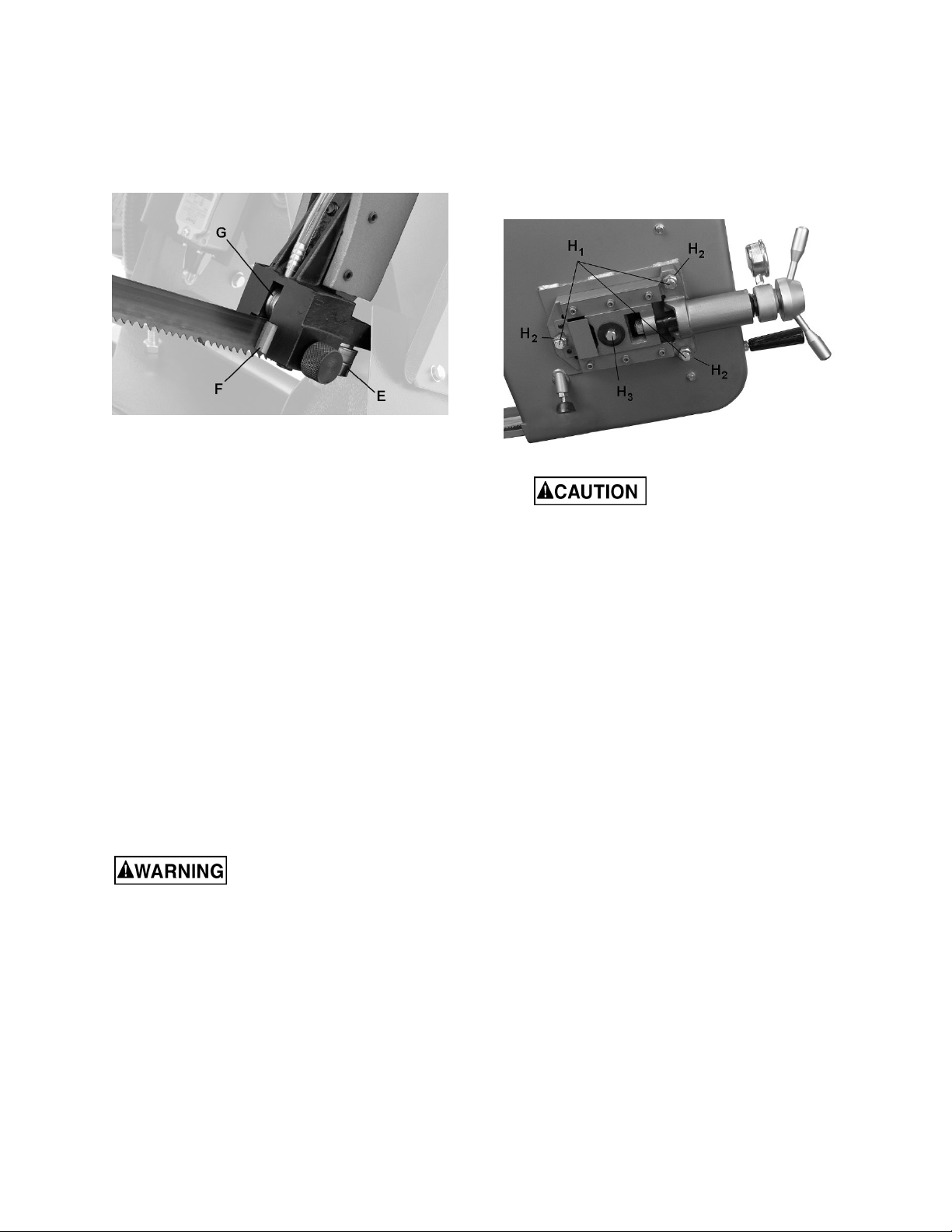
bearing (G), as shown in Figure 8-2.
Figure 8-2: blade guides
NOTE: If roller bearings need adjustment refer
to sect. 8.5.
8. Position blade through upper slot. Put light
tension on blade and work it onto both wheels.
Make sure back of blade is against shoulder
of both wheels.
9. When you are sure that back of blade is against
shoulder of both wheels and properly inserted
into guides, finish putting tension on blade.
10. Connect power and jog blade on/off button to
be sure blade is in place and tracking properly.
If blade is not tracking properly refer to sect. 8.3.
8.2 Blade tension
Blade tension has been preset by the manufacturer;
if further adjustment is required, or after installing a
new blade, turn handwheel (D, Figure 8-1)
clockwise to appropriate tension for the installed
blade.
8.3 Blade tracking
Blade tracking requires saw to
be operating. Use extreme caution and keep
hands away from moving blade areas.
Blade tracking has been initially set by the
manufacturer. Adjustment is rarely required when
blade is correctly welded and used properly. For
proper blade tracking, the back of blade should be
located against blade wheel shoulder. If it is not,
proceed as follows.
NOTE: Do not hurry tracking adjustments. Patience
and accuracy here will pay off with more accurate
cutting and much longer machine and blade life.
1. Raise bow enough to allow motor to operate.
2. Loosen four knobs and open wheel cover (A,
Figure 8-1). Remove upper gap cover (B,
Figure 8-1), lower blade guard (C, Figure 8-1),
and guide brackets (J, Figure 8-1).
3. NOTE: Maintain proper tension at all times
using blade tensioning mechanism.
4. Loosen center locking screws (H
in all three hex adjustment screws (H
, Figure 8-3)
1
).
2
Figure 8-3
While performing the
following, keep blade from rubbing
excessively on wheel shoulder, which can
damage wheel and/or blade.
5. Start saw blade, and slowly turn single hex
adjustment screw (H
, Figure 8-13) to tilt idler
3
wheel. Turn screw outward so that blade starts
to move away from wheel shoulder; then
immediately turn screw inward so that blade
stops, then moves slowly back toward shoulder.
6. Turn off saw blade.
7. Hold hex adjustment screws (H
and tighten center locking screws (H
) with a wrench
2
). Make
1
sure hex adjustment screws do not move while
tightening the center screws.
8. Install the two guide brackets. Position guides
so that bearings just touch the blade. Refer to
sect. 8.5.
9. Install upper gap cover (B, Figure 8-1) and left
blade guard (C, Figure 8-1).
10. Close blade wheel cover (A, Figure 8-1) and
secure with the four knobs.
8.4 Blade guide bracket adjustment
The brackets (J, Figure 8-1) should be set as close
to vise jaw as possible. The right bracket has
minimal adjustment and is set by the manufacturer
to clear the stationary vise jaw. The left bracket can
be moved to accommodate position of floating vise
jaw. Loosen handle and slide bracket into position,
then retighten handle.
9
Page 10
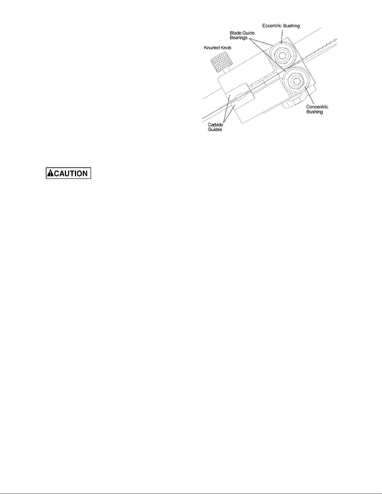
8.5 Blade guide bearing adjustment
Proper adjustment of blade guide bearings is critical
to efficient operation of the saw. The blade guide
bearings have been adjusted by the manufacturer.
They should rarely require adjustment except after
a blade change. Failure to maintain proper blade
adjustment may cause serious blade damage or
inaccurate cuts.
It is always better to try a new blade when cutting
performance is poor. If performance remains poor
after changing the blade, make the necessary
adjustments.
If a new blade does not correct the problem, check
the blade guides for proper spacing. For most
efficient operation and maximum accuracy, provide
only very slight clearance between blade and guide
bearings. The bearings will still turn freely with this
clearance. If the clearance is incorrect, the blade
may track off the drive wheel.
Check blade to make sure
welded section is same thickness as rest of
blade. If blade is thicker at weld, the guide
bearings may be damaged.
If required, adjust guide bearings as follows:
1. Disconnect machine from power source.
2. Two bearing guide assemblies are used in each
set of blade guides. The inner bearing guide
assembly is fixed; the outer bearing guide
assembly is mounted to an eccentric shaft and
is adjustable.
3. On the inner bearing guide, hold the bushing
with the 19mm wrench and loosen the center
locking screw with a hex wrench (see Figure 8-
4).
4. Position the bearing by turning the bushing. Set
the bearing in contact with blade then back it off
very slightly so that it will still turn by hand.
5. Tighten center locking screw while holding the
eccentric bushing in position with the 19mm
wrench.
6. The support bearing (see G, Figure 8-2)
prevents deflection of blade under pressure
from the workpiece. Set support bearing so that
it nearly contacts back edge of blade but can
still be turned by hand when blade is not
running.
7. Use knurled knob to tighten carbide guides
against blade. Do not overtighten.
Figure 8-4
8.6 Test cutting to verify adjustment
Test cuts can be used to determine whether or not
you have adjusted the blade accurately. Use 2-inch
round bar stock to perform these test cuts, as
follows:
1. With bar stock securely clamped in the vise,
make a cut through the bar stock (see Figure 8-
5).
2. Mark the top of the bar stock.
3. Move the bar stock about 1/4-inch past the
blade so that you can begin a second cut.
4. Rotate the bar stock 180 degrees so the mark
you made is now at the bottom of the cut.
5. Make a cut through the bar stock.
6. Use a micrometer to measure the thickness
variation of the disk you have cut from the bar
stock. Measure at top and bottom of disk.
The saw blade can be considered correctly adjusted
when the variation measure is no more than 0.012
inch across the face of the disk.
If you do not have a piece of 2-inch bar stock
available for a test cut, use a larger diameter test
piece rather than a smaller one. The maximum
thickness variation on any test piece should be no
more than 0.003 inch, per side, per inch of stock
diameter.
10
Page 11
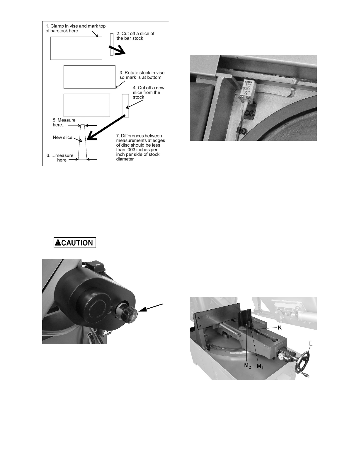
8.8 Broken blade safety device
If blade breaks during operation, the limit switch
shown in Figure 8-7 will automatically stop the
machine.
Figure 8-7
Figure 8-5
8.7 Changing blade speed
1. Raise blade approximately six inches above
workpiece and turn feed rate knob to zero.
2. Turn power on, and turn speed adjuster knob
(Figure 8-6) to match appropriate material. Turn
counterclockwise to increase speed, clockwise
to decrease.
Turn speed adjuster knob
only when blade is running.
8.9 Vise adjustments
8.9.1 General movements
1. Place workpiece between vise jaws with
required amount to be cut-off extending out past
blade. (Figure 8-9 shows recommended
positioning of various workpiece shapes within
the vise.)
2. Lift rack block (K, Figure 7-8) and manually
slide floating vise jaw in general proximity to
workpiece. Let block fall to re-engage rack.
3. Model MSA: Rotate handwheel (L) to tighten
jaw against workpiece
Model MSAH: Use vise button on control panel
to tighten jaw.
4. To retract vise jaw, lift rack block and manually
slide floating jaw away (all models), or use vise
release button on control panel (model MSAH
only).
Figure 8-6: blade speed adjustment
3. The indicator on the mechanism shows speeds
in graduations of 90,130,170,235,370 FPM.
The graduations may not match the
recommended feed rate; an approximate speed
may therefore be required. For example, to set
a speed rate of 110 feet per minute, the
indicator would be set about midway between
70 and 130 FPM.
4. Sect. 12.0 shows recommended speeds for
basic materials. Refer to a machinist’s
handbook for more detailed recommendations.
Figure 8-8: vise adjustments
8.9.2 Miter cuts
If making an angled cut, the fixed vise jaw remains
stationary, while bow and bed are rotated (see sect.
8.12 for miter angle adjustments).
11
Page 12

Loosen locking bolt (M1, Figure 7-8) and adjust
floating jaw against workpiece so that it conforms to
workpiece shape. If needed, slightly loosen hex bolt
) to allow easier movement. Tighten locking bolt
(M
2
(M
) before operating.
1
8.11 Limit switch adjustment
Limit switches have been correctly adjusted by the
manufacturer. If further adjustment is required,
proceed as follows.
8.11.1 Upper Limit Switch
The upper limit switch stops bow at highest position.
To set upper limit switch, loosen handle on support
bracket (Figure 8-11). Slide limit switch to desired
trip point; use scale on post as a general guide.
Tighten handle.
Figure 8-11
Figure 8-9
8.10 Adjusting work stop
The work stop assembly (Figure 8-10) is used when
multiple pieces will be cut to identical length. Simply
adjust rod (A), L-bracket (B), and stop (C) to desired
positions, and tighten all handles/levers.
Figure 8-10: work stop
8.11.2 Lower Limit Switch
The lower limit switch must be set so that blade
stops after workpiece has been cut through. To
adjust, loosen jam nut (D, Figure 8-12) and turn stop
screw (E) as required. Retighten jam nut.
Figure 8-12
8.12 Miter angle adjustment
1. Pull both locking handles (Figure 8-13) toward
front of machine.
2. Manually push bow into desired position. An
angle reference scale is mounted to rear of left
slide.
3. Push both locking handles backward until tight.
12
Page 13

Figure 9-1
Figure 8-13
9.0 Operating controls
Refer to Figure 9-1.
Power Indicator Light (A) – Illuminates whenever
machine is receiving electrical power.
Blade Start (B) – Press to start blade movement.
Blade Stop (C) – Press to stop blade movement.
Emergency Stop (D) – Press to instantly stop all
machine functions. To restart machine, rotate Estop button clockwise until it releases.
Bow Up (E) – Press to raise bow while in Automatic
Mode. Bow will rise until limit switch is activated.
This button is rendered inactive in all modes while
blade is engaged in workpiece.
Bow Down (F) – Press to lower bow while in
Automatic Mode. This button is rendered inactive in
all modes while blade is engaged in workpiece.
Hydraulic Vise Close (G) – Press and hold to
clamp workpiece in vise [HBS-1220MSAH only].
Hydraulic Vise Open (H) – Press and hold to
release workpiece in vise [HBS-1220MSAH only].
Coolant Switch (J) – Turn knob to “I” to start
coolant flow. Turn to “O” to stop coolant flow. Flow
may also be regulated at the two valves located atop
the bow.
Bow Feed Rate Control (K) – sets speed of bow
descent, i.e. amount of downward force that is
applied to workpiece. The feed rate is proportional
to the opening of the valve. When set to zero, bow
is locked in raised position. Turn knob
counterclockwise to increase feed rate; clockwise to
reduce feed rate.
Manual/Auto Selector (L) – Choose manual or
automatic bow movement.
10.0 Operation
Refer to Figure 9-1.
10.1 Manual mode
1. Raise bow and set feed rate knob to zero.
2. Make sure workpiece is secure within vise and
set for desired width of cut.
3. Make sure left blade guide bracket is adjusted
as close as possible to left vise jaw.
4. Turn selector switch (L) to manual mode.
5. Press Start (B) to begin blade movement.
Activate coolant flow (J).
6. Turn downfeed control (K) to desired rate. Bow
will descend until operation is complete. Then
blade stops and bow remains in down position.
7. Press and hold Bow Up (E) to return bow to
raised position, then release button.
NOTE: In manual mode, Bow Up/Down and Vise
Open/Close buttons (E/F/G/H) are rendered inactive
while blade is engaging workpiece.
If E-stop (D) is pressed in manual mode, all
functions will cease. While E-stop is engaged, you
may press and hold Blade Up button (E) to return
bow to raised position. Release the button and bow
will stop functioning. To resume operations, rotate
E-stop button clockwise until it disengages.
10.2 Automatic mode
1. Raise bow and set feed rate knob to zero.
2. Make sure workpiece is secure within vise and
set for desired width of cut.
3. Turn switch (L) to auto mode.
4. Press Start (B) to begin blade movement.
5. Turn downfeed control (K) to desired rate. Bow
will descend until operation is complete. Then
blade stops and bow will automatically return to
raised position.
6. If Stop (C) is pressed during the operation, both
blade and bow will stop. Press and hold Bow Up
(E) to return bow to raised position.
13
Page 14

NOTE: In auto mode, Bow Up/Down and Vise
Open/Close buttons (E/F/G/H) are rendered inactive
while blade is engaging workpiece.
If E-stop (D) is pressed in auto mode, all functions
will cease. While E-stop is engaged, you may press
and hold Blade Up button (E) to return bow to raised
position. Release the button and bow will stop
functioning. To resume operations, rotate E-stop
button clockwise until it disengages.
10.3 Blade selection
The HBS-1220MSA/H is provided with a blade
adequate for a variety of jobs on a variety of
common materials. A 4/6 vari tooth bi-metal blade
(5512107) and a 6/10 vari tooth bi-metal blade
(5512108) are also available from JET.
Sect. 12.0 shows recommended speeds for various
materials. These selections, while appropriate for
many shop cutting needs, do not encompass the
wide variety of blades of special configuration (tooth
pitch and set) and special alloys for cutting unusual
or exotic materials.
A coarse blade could be used for a solid steel bar
but a finer tooth blade would be used on a thin-wall
tube. In general, the blade choice is determined by
the thickness of the material; the thinner the
material, the finer the tooth pitch.
A minimum of three teeth should be on the
workpiece at all times for proper cutting. The blade
and workpiece can be damaged if the teeth are so
far apart that they straddle the workpiece.
For very high production on cutting of special
materials, or for hard-to-cut materials such as
stainless steel, tool steel, or titanium, ask your
industrial distributor for more specific blade
recommendations.
Also, the supplier who provides the workpiece
material should be prepared to provide very specific
instructions regarding the best blade (and coolant or
cutting fluid, if needed) for the material and shape
supplied.
10.4 Blade break-in procedure
New blades are very sharp and, therefore, have a
tooth geometry which is easily damaged if a careful
break-in procedure is not followed. Consult the
blade manufacturer’s literature for break-in of
specific blades on specific materials. However, the
following procedure will be adequate for break-in of
JETsupplied blades on lower alloy ferrous materials.
1. Clamp a round section workpiece in the vise.
The workpiece should be 2 inches or larger in
diameter.
2. Set the saw on low speed. Start the cut with a
very light feed rate.
3. When the saw has completed 1/3 of the cut,
increase the feed rate slightly and allow the saw
to complete the cut.
4. Keep the same hydraulic cylinder setting and
begin a second cut on the same or similar
workpiece.
5. When the blade has completed about 1/3 of the
cut, increase the feed rate. Watch the chip
formation until cutting is at its most efficient rate
(see sect. 10.5) and allow the saw to complete
the cut.
6. The blade is now considered ready for regular
service.
10.5 Evaluating cutting efficiency
Is the blade cutting efficiently? The best way to
determine this is to observe the chips formed by the
cutting.
If chip formation is powdery, then feed rate is much
too light, or the blade is dull.
If chips are curled, but colored — that is, either blue
or straw-colored from heat generated during the cut
— then feed rate is too high.
If chips are slightly curled and are not colored by
heat, the blade is sufficiently sharp and is cutting at
an efficient rate.
11.0 User-maintenance
Always disconnect power to
machine before performing maintenance,
unless indicated otherwise. Failure to comply
may result in serious personal injury.
Clean up accumulated saw cuttings after use. Make
sure lead screw is kept free of saw cuttings and
other material that would cause damage.
Remove dust or debris from motor fan area with
compressed air or vacuum.
If power cord is worn, cut, or damaged in any way,
have it replaced immediately.
Release tension on blade if saw will not be used for
a time.
Periodically clean chip sludge from cutting fluid
basin.
A handle is provided for
manually lifting bow for servicing purposes. If
bow is raised without the assistance of the
hydraulic controls, use appropriate blocking to
prevent bow from falling. See Figure 11-1.
Failure to comply may cause injury.
14
Page 15

Figure 11-1: blocking example
11.1 Lubrication
See sect. 11.3, Table 3, for lubrication chart.
All ball bearings are permanently lubricated and
sealed. They require no further attention.
Use a light machine oil to lubricate moving parts as
needed.
Periodically apply light coat of machine oil to
exposed metal surfaces, such as vise bed, to
prohibit rust.
equivalent, until level reaches dot in middle of
sight glass.
5. Reinstall fill plug.
6. Lower bow. Recheck sight glass, top off if
needed.
11.1.2 Servicing hydraulic oil
1. Disconnect machine from power source.
2. Remove hydraulic reservoir access panel.
3. Check oil level (A, Figure 11-3). If level is below
yellow (upper) line, the reservoir should be
filled.
4. Disconnect electrical power.
5. Remove reservoir fill cap (B).
6. Add oil up to yellow (upper) line. Install fill cap.
7. If a significant amount of oil must be added,
check for oil leaks in pump components, lines,
and hydraulic cylinder. Correct source of
leakage before operating saw.
8. Connect electrical power. Raise and lower bow
to confirm that saw is operating correctly.
11.1.1 Gear box
Drain and refill gear box according to Table 3
recommendations.
To check gear box oil level, place bow in down
position and wait a few moments for oil to settle.
Check level in sight glass on side of gear casing.
Correct level is dot in middle of sight glass.
To change gear box oil:
1. Connect machine to power and raise bow to
highest position.
2. Unscrew and remove drain plug (Figure 11-2),
and allow lubricant to drain completely. Follow
local regulations for proper disposal of used oil.
Figure 11-2: gear box drain plug
3. Reinstall drain plug.
4. Remove fill plug at opposite side of gear case
(next to sight glass) and insert approximately
850 mL (1/4 gal.) of
Mobil® SHC Gear Oil 460, or
Figure 11-3: hydraulic oil servicing
11.1.3 Servicing cutting fluid
Pour cutting fluid or coolant mixture into chip tray so
that it drains through strainer into basin. The sight
glass is located on front of base.
Numerous cutting fluids on the market are
formulated for special applications. Consult your
local distributor for details if you have a long range
production task or are required to cut more exotic
materials. Refer to the cutting fluid provider’s
instructions for mixing recommendations and fluid
life span.
To drain cutting fluid, use drain plug located on left
side of machine base, near pump access panel.
Follow local regulations when disposing of used
machine fluids.
15
Page 16

11.2 Additional servicing
Any additional servicing should be performed by
authorized service personnel.
11.3 Lubrication schedule
Item or location Recommended lubricant Frequency
Vise lead screw bearing
housing
Vise lead screw Light machine oil Monthly
Hydraulic cylinder pivot
areas
Blade tension screw General purpose grease Every 6 months
Blade brush bearing Light machine oil Monthly
Gear box Mobil® SHC Gear Oil 460, or
Cutting fluid (May vary based upon
Hydraulic oil Mobil DTE® Excel Series 32
Light machine oil Monthly
Light machine oil Every 6 months
Check periodically; top off as needed.
equivalent multi-purpose gear
oil
operating needs)
(or equivalent ISO 32)
Change after first 50 hours of operation; then at least
once a year.
Check level and fluid quality periodically. For flush
and refill schedule, refer to cutting fluid/coolant
supplier’s instructions.
Check periodically; top off as needed.
Change every 1 to 2 years or after 3000 operating
hours, whichever comes first.
Table 3
16
Page 17

12.0 Blade speed recommendations
Speed FPM Material
90 Tool steel, stainless steel, alloy steel, copper alloys, hard cast iron
130 Mild steel, soft cast iron, medium hard brass, medium hard bronze
170 Soft brasses and bronzes, hard aluminum
235 Plastic, soft and medium aluminum, other light materials
370 Plastic, wood, other light materials
Table 4
13.0 Troubleshooting HBS-1220MSA/MSAH
Table 5
* WARNING: Some corrections may require a qualified electrician.
Symptom Possible Cause Correction*
Motor will not start. No incoming power. Check plug connection.
Blown electrical panel fuses or tripped
circuit breakers.
Defective motor, switch, power cable, or
plug.
Motor runs too hot. Excessive blade tension. Reduce tension.
Drive belt tension too high. Reduce belt tension.
Blade too coarse for material (especially
with tubular stock).
Blade too fine for material (especially with
heavier, soft material).
Insufficient gear lubrication. Make sure gearbox is filled to sight glass.
Band Saw vibrates
excessively.
Miter cuts not accurate. Material not clamped properly, or vise
Cuts not square.
Base on uneven surface. Adjust base for even support.
Saw blade has cracks. Replace blade immediately.
Too heavy a cut. Reduce feed rate and blade speed.
screws not tightened.
Blade is worn, cutting crooked. Replace blade.
Feed rate too fast. Decrease feed rate.
Incorrect blade toothing in relation to
workpiece.
Blade is worn, cutting crooked. Replace blade.
Incorrect adjustment of guide bearings. Readjust guide assemblies.
Guide bearings are worn. Replace guide bearings.
Blade guide assemblies too far apart. Adjust guide assemblies as close to
Workpiece incorrectly positioned in vise. Check positioning and clamping in the
Poor blade tension. Check and correct if needed.
Replace fuses, or reset breakers.
Qualified electrician/service personnel
should inspect these items.
Use blade with finer tooth pitch.
Use blade with coarser tooth pitch.
Tighten vise screws securely. Use an
adjustable square or protractor to verify
angle settings.
Check a machinist’s handbook for
recommended blade type.
workpiece as possible.
vise.
17
Page 18

Symptom Possible Cause Correction*
Cuts not square. (cont.)
Finished surface of
workpiece is rough,
unsatisfactory.
Excessive blade
breakage.
Unusual wear on
side/back of blade.
Premature blade
dulling.
No coolant flow.
Blade tracking too far from wheel
shoulders.
Blade is dull. Replace blade.
Improper blade for cutting operation. Check a machinist’s handbook for blade
Feed rate too fast. Reduce feed rate.
Blade tension too low. Increase blade tension.
Incorrect blade tension. Adjust blade tension.
Incorrect blade speed or feed rate. Adjust accordingly.
Workpiece loose in vise. Clamp workpiece securely.
Blade rubs on wheel flange. Adjust blade tracking.
Tooth pitch too coarse for material. Use appropriate blade for material.
Teeth in contact with workpiece before
saw is started.
Blade guides are misaligned. Adjust blade guides as needed.
Blade too thick for wheel diameter. Use thinner blade.
Cracking at weld; poor annealing of blade. Replace blade.
Blade guides worn. Replace guides.
Blade guide bearings not adjusted. Adjust blade guide bearings.
Blade guide bearing bracket is loose. Tighten blade guide bearing bracket
Teeth too coarse. Use finer tooth blade.
Blade speed too fast. Reduce speed.
Inadequate feed rate. Adjust cylinder dial setting as needed.
Hard spots or scale on material. Hard Spots: Increase feed rate. Scale:
Work hardening of material (especially
stainless steel).
Blade installed backwards. Remove blade, twist inside-out and re-
Insufficient blade tension. Adjust tension as needed.
Pump motor burned out. Replace pump.
Filter screen clogged. Clean filter screen.
Coolant level low. Add coolant to tank.
Adjust blade tracking.
recommendations.
Start motor before blade contacts
workpiece.
Reduce speed and increase feed rate.
Increase feed rate.
install.
14.0 Replacement Parts
Replacement parts are listed on the following pages. To order parts or reach our service department, call 1-800274-6848 Monday through Friday, 8:00 a.m. to 5:00 p.m. CST. Having the Model Number and Serial Number of
your machine available when you call will allow us to serve you quickly and accurately.
Non-proprietary parts, such as fasteners, can be found at local hardware stores, or may be ordered from JET.
Some parts are shown for reference only, and may not be available individually.
18
Page 19

14.1.1 HBS-1220MSA/MSAH Base Assembly – Exploded View
19
Page 20

14.1.2 HBS-1220MSA/MSAH Oil Pump Assembly – Exploded View
20
Page 21

14.1.3 HBS-1220MSA/MSAH Base Assembly – Parts List
Index No Part No Description Size Qty
1 ................ HBS1220MSA-01 ...... Machine Base .......................................................... ...................................... 1
1-1 ............. 5512197 .................... Drain Plug ................................................................ 3/8"PT ........................... 1
2 ................ TS-1492071 .............. Hex Cap Screw ........................................................ M12-1.75 x 70 ............... 4
3 ................ TS-1540081 .............. Hex Nut .................................................................... M12-1.75 ....................... 4
4 ................ J-5712921A ............... Coolant Pump .......................................................... 1/8HP 230/460V 3PH ... 1
5 ................ TS-1482031 .............. Hex Cap Screw ........................................................ M6-1.0 x 16 ................... 4
5-1 ............. TS-2360121 .............. Flat Washer ............................................................. M12 ............................... 4
6 ................ 5507596 .................... Hose Fitting ............................................................. ...................................... 1
7 ................ 5507597 .................... Hose Clamp ............................................................. ...................................... 1
8 ................ 5712331 .................... Hose ........................................................................ 5/16" .............................. 1
9 ................ 5507599 .................... Coolant Gauge ........................................................ ...................................... 1
10 .............. TS-1491041 .............. Hex Cap Screw ........................................................ M10-1.5 x 30 ................. 2
10-1 ........... HBS1220MSA-10-1 ... Soft Washer ............................................................. M10 ............................... 2
10-2 ........... TS-1540071 .............. Hex Nut .................................................................... M10-1.5 ......................... 2
10-3 ........... TS-1550071 .............. Flat Washer ............................................................. M10 ............................... 2
11 .............. 5712351 .................... Coolant Pump Bracket ............................................. ...................................... 1
12 .............. J-5512195G .............. Cover Panel ............................................................. ...................................... 1
13 .............. TS-0254011 .............. Socket Head Button Screw ...................................... 1/4"-20 x 3/8" .............. 12
14 .............. J-5507604G .............. Drip Tray .................................................................. ...................................... 1
15 .............. TS-1490021 .............. Hex Cap Screw ........................................................ M8-1.25 x 16 ................. 2
15-1 ........... TS-2361081 .............. Lock Washer ............................................................ M8 ................................. 2
15-2 ........... TS-1550061 .............. Flat Washer ............................................................. M8 ................................. 2
16 .............. TS-1492021 .............. Hex Cap Screw ........................................................ M12-1.75 x 30 ............... 4
17 .............. TS-2360121 .............. Flat Washer ............................................................. M12 ............................... 4
18 .............. TS-1490021 .............. Hex Cap Screw ........................................................ M8-1.25 x 16 ................. 1
19 .............. TS-1550061 .............. Flat Washer ............................................................. M8 ................................. 1
20 .............. 5507609 .................... Turning Slide Bracket .............................................. ...................................... 1
20-1 ........... TS-1524021 .............. Socket Set Screw .................................................... M8-1.25 x 10 ................. 4
21 .............. 5507610 .................... Center Fixed Bracket ............................................... ...................................... 1
21-1 ........... TS-1492031 .............. Hex Cap Screw ........................................................ M12-1.75 x 35 ............... 3
21-2 ........... TS-2361121 .............. Lock Washer ............................................................ M12 ............................... 3
22 .............. 5507611 .................... Thrust Bearing ......................................................... ...................................... 1
23 .............. HBS1220MSA-23 ...... Turning Slide, Right ................................................. ...................................... 1
23-1 ........... TS-1524021 .............. Socket Set Screw ...
24 .............. TS-1550071 .............. Flat Washer ............................................................. M10 ............................... 2
25 .............. TS-1505061 .............. Socket Head Cap Screw ......................................... M10-1.5 x 40 ................. 3
25-1 ........... TS-2361101 .............. Lock Washer ............................................................ M10 ............................... 3
26 .............. TS-1503051 .............. Socket Head Cap Screw ......................................... M6-1.0 x 20 ................... 2
27 .............. TS-1491041 .............. Hex Cap Screw ........................................................ M10-1.5x30 ................... 1
27-1 ........... TS-1540071 .............. Hex Nut .................................................................... M10-1.5 ......................... 1
28 .............. 5507616 .................... Bracket .................................................................... ...................................... 1
29 .............. TS-1550071 .............. Flat Washer ............................................................. M10 ............................... 2
30 .............. TS-1505061 .............. Socket Head Cap Screw ......................................... M10-1.5 x 40 ................. 2
30-1 ........... TS-2361101 .............. Lock Washer ............................................................ M10 ............................... 3
31 .............. 5512705 .................... Sliding Nut ............................................................... ...................................... 2
32 .............. TS-1503071 .............. Socket Head Cap Screw ......................................... M6-1.0x30 ..................... 2
32-1 ........... TS-2361061 .............. Lock Washer ............................................................ M6 ................................. 2
33 .............. HBS1220MSA-33 ...... Bracket .................................................................... ...................................... 1
34 .............. TS-1540071 .............. Hex Nut .................................................................... M10-1.5 ......................... 1
35 .............. TS-1491031 .............. Hex Cap Screw ........................................................ M10-1.5 x 25 ................. 1
36 .............. TS-1505031 .............. Socket Head Cap Screw ......................................... M10-1.5 x 25 ................. 2
37 .............. HBS1220MSA-37 ...... Mounting Bracket ..................................................... ...................................... 1
38 .............. TS-149105 ................ Hex Cap Screw ........................................................ M10-1.5 x 35 ................. 2
38-1 ........... TS-2361101 .............. Lock Washer ............................................................ M10 ............................... 2
38-2 ........... TS-1550071 .............. Flat Washer ............................................................. M10 ............................... 2
39 .............. HBS1220MSA-39 ...... Locking Knob ........................................................... 3/8"-16 .......................... 1
40 .............. HBS1220MSA-40 ...... Handle ..................................................................... M12 x 25 ....................... 1
41 .............. 5712421 .................... Work Stop Bracket ................................................... ...................................... 1
42 .............. 5712451 .................... Work Stop ................................................................ ...................................... 1
43 .............. 5712431 .................... Work Stop Rod ........................................................ ...................................... 1
................................................. M8-1.25 x10 ................ 12
21
Page 22

Index No Part No Description Size Qty
44 .............. J-5507628G .............. Support .................................................................... ...................................... 1
44-1 ........... TS-1503071 .............. Socket Head Cap Screw ......................................... M6-1.0 x 30 ................... 1
44-2 ........... TS-2361061 .............. Lock Washer ............................................................ M6 ................................. 1
44-3 ........... TS-1550041 .............. Flat Washer ............................................................. M6 ................................. 1
45 .............. HBS1220MSA-45 ...... Thumb Screw .......................................................... 5/16"-18 ........................ 1
46 .............. 5507630 .................... Adjustable Handle ................................................... ...................................... 2
47 .............. HBS1220MSA-47 ...... Cylinder Lower Support Rod ................................... ...................................... 1
48 .............. 5507632 .................... C-Retaining Ring, Ext .............................................. S-20 .............................. 1
49 .............. 5507633 .................... C-Retaining Ring, Ext .............................................. S-25 .............................. 2
50 .............. HBS1220MSA-50 ..... Bed .......................................................................... ...................................... 1
50-1 ........... TS-1491041 .............. Hex Cap Screw ........................................................ M10-1.5 x 30 ................. 1
50-2 ........... TS-1540071 .............. Hex Nut .................................................................... M10-1.5 ......................... 1
51 .............. HBS1220MSA-51 ...... Handwheel Assembly .............................................. ...................................... 1
51-1 ........... TS-0270051 .............. Socket Set Screw .................................................... 5/16"-18 x 1/2" .............. 1
52 .............. TS-1490051 .............. Hex Cap Screw ........................................................ M8-1.25 x 30 ................. 2
52-1 ........... TS-1550061 .............. Flat Washer ............................................................. M8 ................................. 2
53 .............. TS-2361081 .............. Lock Washer ............................................................ M8 ................................. 2
54 .............. J-5512677G .............. Lead Screw Seat ..................................................... ...................................... 1
55 .............. 5512183 .................... Vise Lead Screw ...................................................... ...................................... 1
55-1 ........... KEY5520 ................... Key, Dbl Rd Hd ........................................................ 5 x 5 x 20mm ................ 1
56 .............. 5512122 .................... Pin ........................................................................... ...................................... 1
57 .............. J-5512124 ................. Slide Bracket ........................................................... ...................................... 1
58 .............. J-5512125 ................. Rack Block ............................................................... ...................................... 1
59 .............. TS-1523031 .............. Socket Set Screw .................................................... M6-1.0 x 10 ................... 1
60 .............. J-5512123 ................. Rack ........................................................................ ...................................... 1
61 .............. HBS1220MSA-61 ...... Tank ......................................................................... ...................................... 1
62 .............. 5512191 .................... Hydraulic Motor ....................................................... 1/2HP 230/460V 3PH ... 1
63 .............. 5512190 .................... Hydraulic Pump Assembly ....................................... ...................................... 1
64 .............. 5512187 .................... Solenoid Valve w/Coil .............................................. MSA .............................. 1
.................. 5512187 .................... Solenoid Valve w/Coil .............................................. MSAH ........................... 4
67………..HBS1220MSAH-67 .... Vise Hydraulic Cylinder ........................................... ...................................... 1
67-1……..HBS1220MSAH-67-1 ... Oil Pressure Gauge……………………tank side MSA, vise side MSAH ........ 1
68 .............. TS-1504061 .............. Socket Head Cap Screw ......................................... M8-1.25 x 30 ................. 1
75 .............. TS-155010 ................ Flat Washer ............................................................. M16 ............................... 2
76 .............. HBS1220MSA-76 ...... Lock Handle ............................................................. ...................................... 1
77 .............. 5712571 .................... Needle Bearing ........................................................ ...................................... 2
78 .............. TS-1503031 .............. Socket Head Cap Screw ......................................... M6-1.0 x 12 ................... 2
78-1 ........... TS-2361061 .............. Lock Washer ............................................................ M6 ................................. 2
79 .............. 5507654 .................... Guide Plate .............................................................. ...................................... 1
80 .............. 5512182 .................... Lead Screw Seat ..................................................... ...................................... 1
81 .............. 5512153 .................... Pivot Shaft ............................................................... ...................................... 1
82 .............. TS-2360121 .............. Flat Washer ............................................................. M12 ............................... 2
83 .............. TS-1492011 .............. Hex Cap Screw ........................................................ M12-1.72 x 20 ............... 2
85 .............. J-5512168G .............. Pivot Bracket ........................................................... ...................................... 1
86 .............. TS-2208201 .............. Hex Cap Screw ........................................................ M8-1.25 x 20 ................. 2
87 .............. HBS1220MSA-87 ...... Roller ....................................................................... ...................................... 1
88 .............. BB-6302 .................... Ball Bearing ............................................................. 6302 .............................. 2
89 .............. HBS1220MSA-89 ...... Roller Shaft .............................................................. ...................................... 1
91 .............. HBS1220MSA-91 ...... Adjusting Bracket ..................................................... ...................................... 1
91-1 ........... TS-1540061 .............. Hex Nut .................................................................... M8 ................................. 1
91-2 ........... TS-1504061 .............. Socket Head Cap Screw ......................................... M8-1.25 x 30 ................. 1
92 .............. 5512145 .................... Limit Switch ............................................................. 5101 .............................. 1
92-1 ........... TS-1504041 .............. Socket Head Cap Screw ......................................... M8-1.25 x 20 ................. 4
93 .............. J-5512169G .............. Limit Switch Plate .................................................... ...................................... 1
94 .............. TS-1550061 .............. Flat Washer ............................................................. M8 ................................. 4
95 .............. TS-1490021 .............. Hex Cap Screw ........................................................ M8-1.25 x 16 ................. 2
95-1 ........... TS-2361081 .............. Lock Washer ............................................................ M8 ................................. 2
96 .............. TS-1482011 .............. Hex Cap Screw ........................................................ M6-1.0 x 10 ................... 4
97 .............. 5512163 .................... Limit Switch ............................................................. ...................................... 1
98 .............. 5507671 .................... Plate ........................................................................ ...................................... 2
99 .............. TS-2360121 .............. Flat Washer ............................................................. M12 ............................... 2
100 ............ TS-1492051 .............. Hex Cap Screw ........................................................ M12-1.75 x 50 ............... 3
22
Page 23

Index No Part No Description Size Qty
101 ............ 5512144 .................... Switch Mounting Plate ............................................. ...................................... 1
102 ............ 5512151 .................... Cylinder Cover ......................................................... ...................................... 1
103 ............ 5512159 .................... Switch Stop Plate .................................................... ...................................... 1
103-1 ......... TS-2361061 .............. Lock Washer ............................................................ M6 ................................. 2
103-2 ......... TS-1503041 .............. Socket Head Cap Screw ......................................... M6-1.0 x12 .................... 2
104 ............ TS-1550071 .............. Flat Washer ............................................................. M10 ............................... 1
105 ............ HBS1220MSA-105 .... Handle ..................................................................... ...................................... 1
107 ............ 5512127 .................... Floating Vise Jaw .................................................... ...................................... 1
108 ............ TS-1492031 .............. Hex Cap Screw ........................................................ M12-1.75 x 35 ............... 1
109 ............ 5512130 .................... Locking Bolt ............................................................. ...................................... 1
110 ............ HBS1220MSA-110 .... Beveled Washer ...................................................... M12 ............................... 1
111 ............ HBS1220MSA-111 .... Pivot Pin .................................................................. ...................................... 1
112 ............ HBS1220MSA-112 .... Fixed Vise Jaw......................................................... ...................................... 1
113 ............ TS-1492041 .............. Hex Cap Screw ........................................................ M12-1.75 x 40 ............... 1
113-1 ......... TS-2360121 .............. Flat Washer ............................................................. M12 ............................... 3
114 ............ TS-2361121 .............. Lock Washer ............................................................ M12 ............................... 5
121 ............ HBS1220MSA-121 .... Hydraulic Cylinder ................................................... ...................................... 1
122 ............ TS-2361101 .............. Lock Washer ............................................................ M10 ............................... 3
123 ............ TS-1491041 .............. Hex Cap Screw ........................................................ M10-1.5 x 30 ................. 3
124 ............ J-5512162 ................. Hydraulic Mounting Plate ......................................... ...................................... 1
124-1 ......... 5512148 .................... Retaining Pin ........................................................... ...................................... 1
125 ............ 5512147 .................... Cylinder Pin ............................................................. ...................................... 1
128 ............ F009884 .................... Socket Head Button Screw ...................................... M5-0.8x8 ....................... 4
136………HBS1220MSAH-136 ... Wire Terminal Box ................................................... ...................................... 1
137………HBS1220MSAH-137 ... Wire Terminal Box Cover......................................... ...................................... 1
258 ............ HBS1220MSA-258 .... Rivet ........................................................................ ...................................... 3
265 ............ HBS1220MSA-265 .... Turning Slide, Left ................................................... ...................................... 1
265-1……HBS1220MSA-265-1 ... Angle Scale ............................................................. ...................................... 1
265-2 ......... TS-1505031 .............. Socket Head Cap Screw ......................................... M10-1.5 x 25 ................. 1
267 ............ HBS1220MSA-267 .... Rubber Ring ............................................................ ...................................... 1
268 ............ HBS1220MSA-268 .... Rubber Ring ............................................................ ...................................... 1
271 ............ 5521936 .................... Bushing .................................................................... 3mm .............................. 1
272 ............ 5521936 .................... Bushing .................................................................... 3mm .............................. 1
273 ............ J-5512189G .............. Cover Panel ............................................................. ........
273-1 ......... TS-1490041 .............. Hex Cap Screw ........................................................ M8x25 ........................... 2
.................. LM000322 ................. ID Label, HBS-1220MSA (not shown) ..................... ...................................... 1
.................. LM000323 ................. ID Label, HBS-1220MSAH (not shown)................... ...................................... 1
.................. LM000250 ................. Warning Label (not shown) ...................................... ...................................... 1
.................. HBS1220MSA-TB ..... Toolbox see sect. 6.1 for contents ........................... ...................................... 1
.............................. 1
23
Page 24

14.2.1 HBS-1220MSA/MSAH Bow Assembly – Exploded View
24
Page 25

14.2.2 HBS-1220MSA/MSAH Bow Assembly – Parts List
Index No Part No Description Size Qty
146 ............ BB-51103 .................. Thrust Bearing ......................................................... 51103 ............................ 1
147 ............ HBS1220MSA-147 .... Hydraulic Tension Gauge ........................................ ...................................... 1
148 ............ 5512250 .................... Special Washer ....................................................... ...................................... 1
149 ............ 5512251 .................... Special Spring Washer ............................................ .................................... 18
150 ............ J-5512252G .............. Slide Bracket ........................................................... ...................................... 1
151 ............ TS-2361101 .............. Lock Washer ............................................................ M10 ............................... 3
152 ............ TS-1491101 .............. Hex Cap Screw ........................................................ M10-1.5x60 ................... 3
153 ............ 5512255 .................... Screw Assembly ...................................................... ...................................... 3
154 ............ TS-1523031 .............. Socket Set Screw .................................................... M6-1.0x10 ..................... 1
155 ............ TS-154010 ................ Hex Nut .................................................................... M16-2.0 ......................... 1
156 ............ TS-1492011 .............. Hex Cap Screw ........................................................ M12-1.75 x25 ................ 1
157 ............ TS-2360121 .............. Flat Washer ............................................................. M12 ............................. 1
158 ............ HBS1220MSA-158 .... Slide Block ............................................................... ...................................... 1
159 ............ J-5512260G .............. Gib ........................................................................... ...................................... 2
160 ............ 5512261 .................... Blade Wheel Bracket Shaft ...................................... ...................................... 1
161 ............ TS-1504041 .............. Socket Head Cap Screw ......................................... M8-1.25x20 ................... 6
162 ............ TS-2361081 .............. Lock Washer ............................................................ M8 ............................... 6
163 ............ HBS1220MSA-163 .... Tension Shaft .......................................................... ...................................... 1
164 ............ HBS1220MSA-164 .... Cover Plate .............................................................. ...................................... 1
165 ............ F009884 .................... Socket Head Button Screw ...................................... M5-0.8x8 ....................... 2
166 ............ HBS1220MSA-166 .... Blade Tension Handle Assembly ............................. ...................................... 1
167 ............ HBS1220MSA-167 .... Bow Gap Cover ....................................................... ...................................... 1
168 ............ 5512268 .................... T-Fitting ................................................................... ...................................... 1
169 ............ 5512269 .................... Hose Clamp ............................................................. ...................................... 5
170 ............ HBS1220MSA-170 .... Gear Box Assembly ................................................. ...................................... 1
171 ............ J-5512271 ................. Motor ....................................................................... 3HP 230/460V 3PH ...... 1
172 ............ 5512272 .................... Key, Dbl Rd Hd ........................................................ 8x8x40 mm ................... 1
173 ............ 5512273 .................... Key, Dbl Rd Hd ........................................................ 7x7x45 mm ................... 1
174 ............ J-5512274G .............. Support Bracket Seat .............................................. ...................................... 1
175 ............ TS-2361081 .............. Lock Washer ............................................................ M8 ................................. 3
176 ............ 5512275 .................... Drive Belt ................................................................ 1922V338 ..................... 1
177 ............ TS-1490021 .............. Hex Cap Screw ........................................................ M8-1.25x16 ................... 3
178 ............ J-5512277 ................. Variable Speed Assembly ....................................... ...................................... 1
179 ............ HBS1220MSA-179 .... Special Knob ........................................................... 3/8"
180 ............ 5512279 .................... Special Flat Washer ................................................ ...................................... 1
181 ............ J-5512280 ................. Pulley Cover ............................................................ ...................................... 1
182 ............ J-5512281 ................. Gear Box Pulley ....................................................... ...................................... 1
183 ............ 5512282 .................... Shaft ........................................................................ ...................................... 1
184 ............ J-5512283 ................. Variable Speed Plate ............................................... ...................................... 1
185 ............ 5512284 .................... Plate ........................................................................ ...................................... 2
186 ............ TS-1550061 .............. Flat Washer ............................................................ M8 ................................. 3
189-1 ......... TS-1504031 .............. Socket Head Cap Screw ......................................... M8-1.25x16 ................... 1
189-2 ......... TS-2361081 .............. Lock Washer ............................................................ M8 ................................. 1
189-3 ......... TS-1550061 .............. Flat Washer ............................................................. M8 ................................. 1
190 ............ J-5512285 ................. Bow Assembly ......................................................... ...................................... 1
191 ............ TS-2361101 .............. Lock Washer ............................................................ M10 ............................... 4
192 ............ TS-149105 ................ Hex Cap Screw ........................................................ M10-1.5x35 ................... 4
193 ............ 5512288 .................... Hose ........................................................................ 30mm ............................ 1
194 ............ TS-1492031 .............. Hex Cap Screw ........................................................ M12-1.75x35 ................. 4
195 ............ TS-2361121 .............. Lock Washer ............................................................ M12 ............................... 4
196 ............ 5512291 .................... Flexible Nozzle ........................................................ ...................................... 1
199 ............ 5512294 .................... Rubber Stop ............................................................ ...................................... 2
200 ............ TS-0561051 .............. Hex Nut .................................................................... 1/2"-13 .......................... 1
201 ............ 5512296 .................... Hose Clamp ............................................................. ...................................... 2
202 ............ J-5512297G .............. Blade Bracket (Left) ................................................. ...................................... 1
203 ............ TS-2360121 .............. Flat Washer ............................................................. M12 ............................... 4
204 ............ TS-1492021 .............. Hex Cap Screw ........................................................ M12-1.75x30 ................. 4
205 ............ TS-1482021 .............. Hex Cap Screw ........................................................ M6-1.0x12 ..................... 2
206 ............ TS-2361061 .............. Lock Washer ............................................................ M6 ................................. 2
207 ............ J-5512302G .............. Blade Bracket (Right) .............................................. ...................................... 1
................................ 1
25
Page 26

Index No Part No Description Size Qty
208 ............ TS-1550061 .............. Flat Washer ............................................................. M8 ............................... 11
209 ............ TS-2361081 .............. Lock Washer ............................................................ M8 ................................. 6
210 ............ 5512304 .................... Wire Brush Seat ...................................................... ...................................... 1
211 ............ 5512680 .................... Wire Brush ............................................................... ...................................... 1
212 ............ TS-2361061 .............. Lock Washer ............................................................ M6 ................................. 1
213 ............ 5512107 .................... Blade…………………………………………..1" x 0.035" x 156" 4/6VT ............ 1
.................. 5512108 .................... Blade…………………………………………..1" x 0.035" x 156" 6/10VT .......... 1
214 ............ TS-1505071 .............. Socket Head Cap Screw ......................................... M10-1.5x45 ................... 4
215 ............ TS-2361101 .............. Lock Washer ............................................................ M10 ............................... 4
216 ............ TS-1550071 .............. Flat Washer ............................................................. M10 ............................... 4
217 ............ TS-1550041 .............. Flat Washer ............................................................. M6 ................................. 1
218 ............ TS-1482011 .............. Hex Cap Screw ........................................................ M6-1.0x10 ..................... 1
219 ............ TS-1490021 .............. Hex Cap Screw ........................................................ M8-1.25x16 ................... 2
220 ............ TS-1524021 .............. Set Screw ................................................................ M8-1.25x10 ................... 4
221 ............ HBS1220MSA-221 .... Adjustable Mount Bracket (Right) ............................ ...................................... 1
222 ............ HBS1220MSA-222 .... Adjustable Mount Bracket (Left) .............................. ...................................... 1
223 ............ 5512317 .................... Lock Block ............................................................... ...................................... 2
224 ............ TS-1524031 .............. Socket Set Screw .................................................... M8-1.25x12 ................... 8
225 ............ HBS1220MSA-225 .... Special Knob ........................................................... 3/8"-16 .......................... 2
226 ............ TS-1550071 .............. Flat Washer ............................................................. M10 ............................... 2
227 ............ HBS1220MSA-227 .... Scale ........................................................................ ...................................... 1
228 ............ F009884 .................... Socket Head Button Screw ...................................... M5-0.8x8 ....................... 4
229 ............ TS-1505031 .............. Socket Head Cap Screw ......................................... M10-1.5x25 ................... 2
230 ............ J-5512324G .............. Slide Bracket ........................................................... ...................................... 1
231 ............ J-5512325 ................. ldler Wheel ............................................................... ...................................... 1
232 ............ BB-6206ZZ ................ Ball Bearing ............................................................. 6206ZZ ......................... 3
233 ............ 5512327 .................... Special Washer ....................................................... M12-1.75x35 ................. 1
234 ............ TS-1492011 .............. Hex Cap Screw ........................................................ M12-1.75x25 ................. 4
235 ............ HBS1220MSA-235 .... Blade Guard ............................................................ ...................................... 1
236 ............ 5512330 .................... Guide Bracket (Left) ................................................ ...................................... 1
237 ............ TS-1504061 .............. Socket Head Cap Screw ......................................... M8-1.25x30 ................... 1
238 ............ BB-6208ZZ ................ Ball Bearing ............................................................. 6208ZZ ......................... 4
239 ............ TS-1503041 .............. Socket Head Cap Screw ......................................... M6-1.0x16 ..................... 4
240 ............ 5512684 .................... Rear Blade Guide, Left ............................................ ...................................... 1
241 ............ 5512683 .................... Front Blade Guide
242 ............ 5512678 .................... Eccentric Shaft Assembly ........................................ ...................................... 2
242A .......... TS-1504081 .............. Socket Head Cap Screw ......................................... M8-1.25x40 ................... 4
242B .......... BB-6201ZZ ................ Ball Bearing ............................................................. 6201ZZ ......................... 8
242C .......... 5517141 .................... Eccentric Shaft Bushing .......................................... ...................................... 2
243 ............ 5512340 .................... Shaft ........................................................................ ...................................... 2
244 ............ 5512341 .................... Spring ...................................................................... ...................................... 2
245 ............ 5512342 .................... Adjusting Knob ........................................................ ...................................... 2
246 ............ J-5512343 ................. Drive Wheel ............................................................. ...................................... 1
247 ............ 5512344 .................... Special Washer ....................................................... M12-1.75x50 ................. 1
248 ............ F009532 .................... Hex Cap Screw ........................................................ M12-1.75x20 ................. 1
249 ............ 5512346 .................... Guide Bracket (Right) .............................................. ...................................... 1
250 ............ 5517140 .................... Center Shaft Bushing .............................................. ...................................... 2
251 ............ 5512686 .................... Rear Blade Guide, Right .......................................... ...................................... 1
252 ............ 5512685 .................... Front Blade Guide, Right ......................................... ...................................... 1
253 ............ J-5512350G .............. Blade Wheel Cover .................................................. ...................................... 1
254 ............ TS-1503031 .............. Socket Head Cap Screw ......................................... M6-1.0x12 ..................... 4
255 ............ TS-1482021 .............. Hex Cap Screw ........................................................ M6-1.0x12 ..................... 2
256 ............ TS-2361061 .............. Lock Washer ............................................................ M6 ................................. 2
257 ............ TS-1550041 .............. Flat Washer ............................................................. M6 ................................. 2
258 ............ HBS1220MSA-258 .... Handle ..................................................................... ...................................... 2
259 ............ HBS1220MSA-259 .... Wire Brush Guard .................................................... ...................................... 1
260 ............ F000297 .................... Phillips Pan HD Mach Screw ................................... 1/4"-20x3/8" .................. 6
261 ............ 5517143 .................... Center Shaft Assembly ............................................ ...................................... 2
274 ............ HBS1220MSA-274 .... Hose Clamp ............................................................. ...................................... 1
275 ............ HBS1220MSA-275 .... Hose ........................................................................ ...................................... 1
276 ............ HBS1220MSA-276 .... Copper Tube ............................................................ ...................................... 2
277 ............ TS-1490081 .............. Hex Cap Screw ........................................................ M8-1.25x45 ................... 4
, Left ........................................... ...................................... 1
26
Page 27

Index No Part No Description Size Qty
278 ............ TS-1540061 .............. Hex Nut .................................................................... M8-1.25 ......................... 4
279 ............ HBS1220MSA-279 .... Bracket .................................................................... ...................................... 1
280 ............ TS-0680041 .............. Flat Washer ............................................................. 3/8" ................................ 1
281 ............ HBS1220MSA-281 .... Special Washer ....................................................... ...................................... 1
282 ............ F014010 .................... Key, Dbl Rd Hd ........................................................ 12x8x30 mm ................. 1
283 ............ LM000320 ................. Motor Label, HBS-1220MSA ................................... ...................................... 1
284 ............ JET-203 ..................... JET Logo ................................................................. 203x84mm .................... 1
286 ............ HBS1220MSA-286 .... Block ........................................................................ ...................................... 4
286-1 ......... TS-1490031 .............. Hex Cap Screw ........................................................ M8-1.25x20 ................... 4
287 ............ 5521936 .................... Bushing .................................................................... 3mm .............................. 1
288 ............ TS-0561051 .............. Hex Nut .................................................................... 1/2"-13 .......................... 1
289 ............ HBS1220MSA-289 .... Rubber Stop Holder ................................................. ...................................... 1
290 ............ HBS1220MSA-290 .... Rubber Clamp ......................................................... ACC-3.5 ........................ 2
291 ............ TS-2361121 .............. Lock Washer ............................................................ M12 ............................... 4
292 ............ HBS1220MSA-292 .... Rubber Clamp ......................................................... ACC-2.5 ........................ 2
293 ............ HBS1220MSA-293 .... Special Knob ........................................................... 3/8" ................................ 4
294 ............ TS-1525031 .............. Socket Set Screw .................................................... M10-1.5x16 ................... 4
295 ............ HBS1220MSA-295 .... Bracket .................................................................... ...................................... 1
296 ............ HBS1220MSA-296 .... Blade Break Sensor ................................................. ...................................... 1
297 ............ WB25-808 ................. Socket Head Button Screw ...................................... M4-0.7x7 ....................... 2
298 ............ HBS1220MSA-298 .... Wire Clamp .............................................................. ...................................... 1
299 ............ LM000321 ................. Speed Chart, HBS-1220MSA .................................. ...................................... 1
27
Page 28

14.3.1 HBS-1220MSA/MSAH Control Box Assembly – Exploded View
28
Page 29

14.3.2 HBS-1220MSA/MSAH Control Box Assembly – Parts List
Index No Part No Description Size Qty
115 ............ HBS1220MSA-115 .... Swivel Bushing ........................................................ ...................................... 1
115-1 ......... F006089 .................... C-Retaining Ring, Ext .............................................. S-48 .............................. 1
116 ............ TS-0207031 .............. Socket Head Cap Screw ......................................... 1/4"-20x5/8" .................. 2
117 ............ HBS1220MSA-117 .... Stationary Box Assembly ......................................... ...................................... 1
117-1 ......... TS-1490021 .............. Hex Cap Screw ........................................................ M8-1.25 x 16 ................. 4
117-2 ......... TS-2361081 .............. Lock Washer ............................................................ M8 ................................. 4
117-3 ......... TS-1550061 .............. Flat Washer ............................................................. M8 ................................. 4
118 ............ TS-0207091 .............. Socket Head Cap Screw ......................................... 1/4"-20 x 3/4" ................ 2
119 ............ HBS1220MSA-119 .... Control Column ........................................................ ...................................... 1
120 ............ HBS1220MSA-120 .... Swivel Block ............................................................ ...................................... 1
126 ............ HBS1220MSA-126 .... Control Box .............................................................. ...................................... 1
127 ............ HBS1220MSA-127 .... Control Panel ........................................................... ...................................... 1
.................. HBS1220MSAH-127 . Control Panel (Hydr Vise) ........................................ for Hydraulic vise ......... 1
128 ............ F009884 .................... Socket Head Button Screw ...................................... M5-0.8x8 ....................... 9
129 ............ 5512681 .................... Power Indicator Light ............................................... ...................................... 1
131 ............ 5512682 .................... Emergency Stop Switch........................................... ...................................... 1
135 ............ HBS1220MSAH-135 . Adjusting Screw ....................................................... 1/4”x5/8” ........................ 1
138 ............ 5512237 .................... Stop Switch .............................................................. ...................................... 1
139 ............ 5512238 .................... Start Switch ............................................................. ...................................... 1
140 ............ 5512216 .................... Push Button (Saw Head Down) ............................... ...................................... 1
141 ............ HBS1220MSAH-141 . Manual/Auto Switch ................................................. ...................................... 1
142 ............ HBS1220MSAH-142 . Hydraulic Vise Open Switch ................................... ...................................... 1
143 ............ 5512215 .................... Push Button (Saw Head Up) ................................... ...................................... 1
144 ............ 5512235 .................... Coolant Switch ......................................................... ...................................... 1
145 ............ HBS1220MSAH-145 . Hydraulic Vise Close Switch .................................... ...................................... 1
146 ............ HBS1220MSA-146 .... Handle .................................................................... ...................................... 2
263 ............ HBS1220MSA-263 .... Box Cover ................................................................ ...................................... 1
263-1 ......... F009884 .................... Socket Head Button Screw ...................................... M5-0.8x8 ....................... 4
264 ............ HBS1220MSA-264 .... Connection Box ....................................................... ...................................... 1
266 ............ HBS1220MSA-266 .... Hydraulic Cylinder Dial ............................................ ...................................... 1
29
Page 30

14.4.1 HBS-1220MSA/MSAH Electrical Box Assembly – Exploded View
14.4.2 HBS-1220MSA/MSAH Electrical Box Assembly – Parts List
Index No Part No Description Size Qty
65 .............. HBS1220MSA-65 ............... Keyed Door Latch ........................................... ...................................... 1
70 .............. HBS1220MSA-70 ............... Electric Box Door Cover .................................. ...................................... 1
71 .............. HBS1220MSA-OMM230 .... Overload for Main Motor ................................. 7.2-10A (230V) ............. 1
.................. HBS1220MSA-OMM460 .... Overload for Main Motor ................................. 3.5-4.8A (460V) ............ 1
.................. HBS1220MSA-OOP230 ..... Overload for Oil Pump ..................................... 1.4-2A (230V) ............... 1
.................. HBS1220MSA-OOP460 ..... Overload for Oil Pump ..................................... 0.75-1 A (460V) ............ 1
71A ............ RU4S-C-A110 .................... Relay…………………………………………..2pcs MSA, 4pcs MSAH .. 2/4
.................. RJ2S-CL-A110 ................... Relay ............................................................... ...................................... 2
72 .............. HBS1220MSA-72 ............... Motor Contactor .............................................. CU-11 .......................... 3
73 .............. HBS1220MSA-73 ............... Transformer ..................................................... 150VA 230/460/110V .... 1
74 .............. 262-301 .............................. Power Circuit Terminal Block .......................... Left Side ....................... 1
.................. 261-301 .............................. Power Circuit Terminal Block .......................... Right Side .................... 1
134 ............ HBS1220MSA-134 ............. Electric Panel Complete .................................. ...................................... 1
.................. HBS1220MSAH-134 .......... Electric Panel Complete .................................. ...................................... 1
269 ............ HBS1220MSA-FU2A .......... Fuse ................................................................ 2A (230V input) ............. 2
.................. HBS1220MSA-FU1.5A ....... Fuse ................................................................ 1.5A (230V output) ........ 2
.................. HBS1220MSA-FU1A .......... Fuse ................................................................ 1A (460V input) ............. 2
.................. HBS1220MSA-FU1.5A ....... Fuse ................................................................ 1.5A (460V output) ........ 2
270 ............ HBS1220MSA-270 ............. Fuse Bracket ................................................... ...................................... 4
30
Page 31

15.0 Electrical Connections
15.1.1 HBS-1220MSA wiring diagram
31
Page 32

15.1.2 HBS-1220MSA wiring diagram (cont.)
15.1.3 HBS-1220MSA electrical panel diagram
32
Page 33

15.2.1 HBS-1220MSAH wiring diagram
33
Page 34

15.2.2 HBS-1220MSAH wiring diagram (cont.)
34
Page 35

15.2.3 HBS-1220MSAH electrical panel diagram
15.3.1 HBS-1220MSA/MSAH voltage conversion diagrams
35
Page 36

16.0 Warranty and service
JET warrants every product it sells against manufacturers’ defects. If one of our tools needs service or repair, please
contact Technical Service by calling 1-800-274-6846, 8AM to 5PM CST, Monday through Friday.
Warranty Period
The general warranty lasts for the time period specified in the literature included with your product or on the official
JET branded website.
JET products carry a limited warranty which varies in duration based upon the product. (See chart below)
Accessories carry a limited warranty of one year from the date of receipt.
Consumable items are defined as expendable parts or accessories expected to become inoperable within a
reasonable amount of use and are covered by a 90 day limited warranty against manufacturer’s defects.
Who is Covered
This warranty covers only the initial purchaser of the product from the date of delivery.
What is Covered
This warranty covers any defects in workmanship or materials subject to the limitations stated below. This warranty
does not cover failures due directly or indirectly to misuse, abuse, negligence or accidents, normal wear-and-tear,
improper repair, alterations or lack of maintenance. JET woodworking machinery is designed to be used with Wood.
Use of these machines in the processing of metal, plastics, or other materials outside recommended guidelines may
void the warranty. The exceptions are acrylics and other natural items that are made specifically for wood turning.
Warranty Limitations
Woodworking products with a Five Year Warranty that are used for commercial or industrial purposes default to a
Two Year Warranty. Please contact Technical Service at 1-800-274-6846 for further clarification.
How to Get Technical Support
Please contact Technical Service by calling 1-800-274-6846. Please note that you will be asked to provide proof
of initial purchase when calling. If a product requires further inspection, the Technical Service representative will
explain and assist with any additional action needed. JET has Authorized Service Centers located throughout the
United States. For the name of an Authorized Service Center in your area call 1-800-274-6846 or use the Service
Center Locator on the JET website.
More Information
JET is constantly adding new products. For complete, up-to-date product information, check with your local distributor
or visit the JET website.
How State Law Applies
This warranty gives you specific legal rights, subject to applicable state law.
Limitations on This Warranty
JET LIMITS ALL IMPLIED WARRANTIES TO THE PERIOD OF THE LIMITED WARRANTY FOR EACH PRODUCT.
EXCEPT AS STATED HEREIN, ANY IMPLIED WARRANTIES OF MERCHANTABILITY AND FITNESS FOR A
PARTICULAR PURPOSE ARE EXCLUDED. SOME STATES DO NOT ALLOW LIMITATIONS ON HOW LONG AN
IMPLIED WARRANTY LASTS, SO THE ABOVE LIMITATION MAY NOT APPLY TO YOU.
JET SHALL IN NO EVENT BE LIABLE FOR DEATH, INJURIES TO PERSONS OR PROPERTY, OR FOR
INCIDENTAL, CONTINGENT, SPECIAL, OR CONSEQUENTIAL DAMAGES ARISING FROM THE USE OF OUR
PRODUCTS. SOME STATES DO NOT ALLOW THE EXCLUSION OR LIMITATION OF INCIDENTAL OR
CONSEQUENTIAL DAMAGES, SO THE ABOVE LIMITATION OR EXCLUSION MAY NOT APPLY TO YOU.
JET sells through distributors only. The specifications listed in JET printed materials and on official JET website are
given as general information and are not binding. JET reserves the right to effect at any time, without prior notice,
those alterations to parts, fittings, and accessory equipment which they may deem necessary for any reason
whatsoever. JET
Product Listing with Warranty Period
90 Days – Parts; Consumable items
1 Year – Motors; Machine Accessories
2 Year – Metalworking Machinery; Electric Hoists, Electric Hoist Accessories; Woodworking Machinery used
for industrial or commercial purposes
5 Year – Woodworking Machinery
Limited Lifetime – JET Parallel clamps; VOLT Series Electric Hoists; Manual Hoists; Manual Hoist
Accessories; Shop Tools; Warehouse & Dock products; Hand Tools; Air Tools
NOTE: JET is a division of JPW Industries, Inc. References in this document to JET also apply to JPW Industries,
Inc., or any of its successors in interest to the JET brand.
®
branded products are not sold in Canada by JPW Industries, Inc.
36
 Loading...