

Page 1

- - - - - - - - -- --
--- - -------
..JET
EQUIPMENT & TOOLS
OPERATOR'S MANUAL
HBS-916W & 1018W Bandsaws
j--
p
JET EQUIPMENT &.TOOLS, INC.
A WMH Company
www.jettools.com
.
.
P.O. BOX 1349
Auburn, WA 98071-1349
e-mail jet@jettools.com
253-351-6000
Fax 253-939-8001
M-414468 2/99
Page 2
Important Information
1-YEAR
LIMITED WARRANTY
JET offers a one-year limited
warranty on this product
REPLACEMENT PARTS
Replacement parts for this tool are available directlyform JET Equipment& Tools.
To place an order, call 1-800-274-6848. Pleasehavethefollowing information ready:
1. Visa, MasterCard, or Discover Card number
2. Expirationdate
3. Part number listed within this manual
4. Shipping address other than a PostOffice box.
REPLACEMENT PART WARRANTY
JET Equipment & Tools makes every effort to assure that parts meet high quality and durability standards
and warrants to the original retail consumer/purchaserof our parts that each such part(s) to be free from
defects in materials and workmanshipfor a period of thirty (30) days from the date of purchase.
PROOF OF PURCHASE
Please retain your dated sales receiptas proof of purchaseto validate the warranty period.
LIMITED TOOL AND EQUIPMENTWARRANTY
JET makes every effort to assure that its products meet high quality and durability standards and warrants to the
original retail consumer/purchaser of our products that each product be free from defects in materials and
workmanship as follows: 1 YEAR LIMITED WARRANTY ON THIS JET PRODUCT. Warranty does not apply to
defects due directly or indirectly to misuse, abuse, negligence or accidents, repairs or alterations outside our
facilities or to a lack of maintenance. JET LIMITS ALL IMPLIED WARRANTIES TO THE PERIOD SPECIFIED
ABOVE FROM THE DATE THE PRODUCTWAS PURCHASED AT RETAIL. EXCEPT AS STATED HEREIN, ANY
IMPLIED WARRANTIES OR MECHANTABILITY AND FITNESS ARE EXCLUDED. SOME STATES DO NOT
ALLOW LIMITATIONS ON HOW LONG THE IMPLIED WARRANTY LASTS, SO THE ABOVE LIMITATION MAY
NOT APPLY TO YOU. JET SHALL IN NO EVENT BE LIABLE FOR DEATH, INJURIES TO PERSONS OR
PROPERY OR FOR INCIDENTAL, CONTINGENT, SPECIAL OR CONSEQUENTIAL DAMAGES ARISING FROM
THE USE OF OUR PRODUCTS. SOME STATESDONOTALLOWTHI; I;XCiLU~IONORLIMITATIONOF
INCIDENTAlORCONS~OUENTIAlDAMAG~S,~o T~~ AQOV~LIMITATIO~O~ ~~~LUQIO~UA V ~CT A~~L V
TO YOU. To take advantage of this warranty, the product or part must be returned for examination, postage
prepaid, to an authorized service station designated by our Auburn office. Proof of purchase date and an
explanation of the complaint must accompany the merchandise. If our inspection discloses a defect, JET will either
repair or replace the product or refund the purchase price, if we cannot readily and quickly provide a repair or
replacement, if you are willing to accept such refund. JET will return repaired product or replacement at JET's
expense, but if it is determined there is no defect, or that the defect resulted from causes not within the scope of
JET's warranty, then the user must bear the cost of storing and returning the product. This warranty gives you
specific legal rights, and you have other rights, which vary, from state to state.
JET Equipment & Tools. P.O. Box 1349, Auburn, WA 98071-1349 . (253) 351-6000
Page 3
it WARNING
.
Read and understand the entire
instruction manual before attempting
assembly or operation.
.
All JET bandsaws are designed and
intended for use by properly trained and
experienced personnel only. If you are
not familiar with the proper and safe
operation of a bandsaw, do not use until
proper training and knowledge have
been obtained.
.
Always wear approved safety glasses/face
shields while using this machine.
.
Make certain the machine is properly
grounded.
.
Giveyour work undivided attention. Looking
around,carrying on a conversation, and
"horse-play"are careless acts that can
result in serious injury.
.
Keepvisitors a safe distance from the work
area.
.
Use recommendedaccessories; improper
accessories may be hazardous.
.
Make a habit of checking to see that keys
and adjusting wrenches are removed before
turning on the machine.
.
Always keep hands and fingers away from
the bladewhen the machine is running.
.
Before operating the machine, removetie,
rings,watches, otherjewelry, and roll up
sleeves above the elbows. Removeall
loose clothing and confine long hair. Do
NOT wear gloves.
.
Keepthe floor around the machineclean
and free of scrap material, oil and grease.
.
Keep machine guards in place at all times
when the machine is in use. If removedfor
maintenance purposes, use extreme caution
and replace the guards immediately.
.
Do NOT over reach. Maintaina balanced
stance at all times so that you do notfall or
lean against blades or other movingparts.
.
Make all machine adjustmentsor
maintenancewith the machineunplugged
from the power source.
.
Use the right tool. Don'tforce a tool or
attachment to do ajob which it was not
designed for.
.
Never hand holdthe material. Always use
the vise and clamp it securely.
.
Keepbelt guard, bladeguards, and wheel
covers in place and inworking order.
.
Always provideadequate support for long
and heavy material.
.
Use a sharp bladeand keepmachine clean
for best and safest performance.
.
Failureto comply with all of these warnings
may cause serious injury.
.
Replace warning labels if they become
obscured or removed.
.
Make certain the motor switch is in the OFF
position before connecting the machineto
the power supply.
Page 4
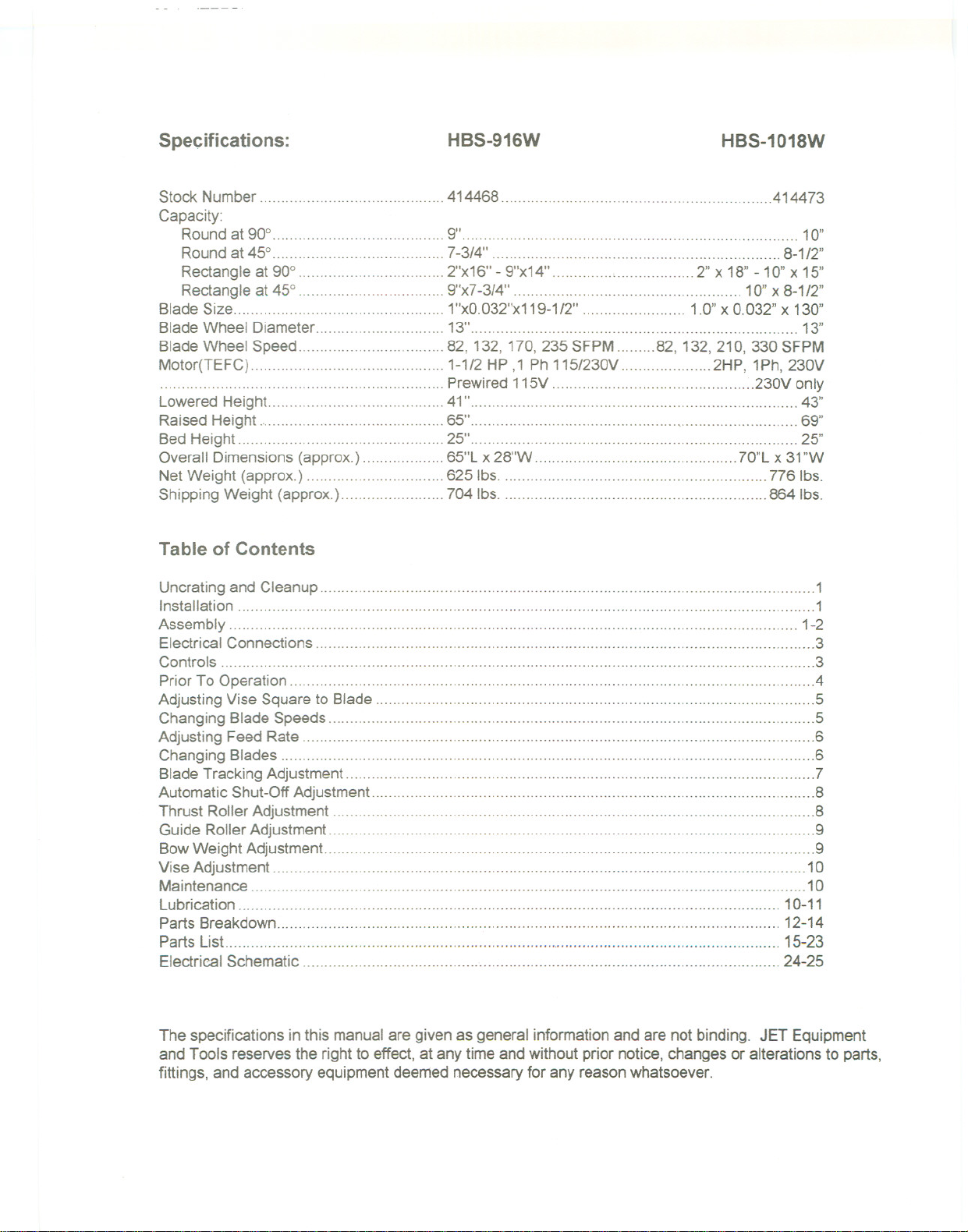
Specifications:
HBS-916W
HBS-1018W
StockNumber ""'" 414468 ..414473
Capacity:
Round at 900 9" 10"
Round at 450 7-3/4" 8-1/2"
Rectangle at 900 2"x16" - 9"x14"
' 2" x 18"- 10"x 15"
Rectangle at 450 9"x7-3/4" """""""""""""'"'''''''''''''''''''''''' 10"x 8-112"
Blade Size 1"xO.032"x119-1I2" 1.0"x 0.032" x 130"
Blade Wheel Diameter 13" 13"
Blade Wheel Speed 82,132,170,235 SFPM 82,132,210,330 SFPM
Motor(TEFC) 1-1I2 HP ,1 Ph 115/230V 2HP, 1Ph, 230V
Prewired 115V """"""""'''''''''''''''''''''''''''''' .230V only
Lowered Height ..0...41 " ".. """""'''' ..'"'' "'"''''
Raised Height 65"... " '''''' ""'''''' 69"
Bed Height 0" """"""""""""" 25" 0 0 0.00"""""""',," 0.0 25"
Overall Dimensions (approx.) "'"'' 65"L x 28"W """""""""""""""'"'''''''''''''' 70"L x 31"W
Net Weight (approx.) """"'''''''''''''''''''''''' 625 Ibs. " 776 Ibs.
Shipping Weight (approx.) 704lbs. 864Ibs.
43"
Table of Contents
Uncrating and Cleanup 0 0""""""',"'...0 0...1
Installation .1
Assembly 1-2
ElectricalConnections 0...0 0 0..3
Controls 0 0 00 0 0 0"""""""""""""""" 0 0 3
Prior To Operation 4
Adjusting Vise Square to Blade "'"'''''''''''''''''''''''''''''''''''''''''''''''''''''''''''''' ''''''' 5
Changing Blade Speeds 0 5
Adjusting Feed Rate 0 6
Changing Blades 6
Blade Tracking Adjustment """""""'"'''' 0.7
Automatic Shut-Off Adjustment 0.0 0 0 8
Thrust Roller Adjustment 0 8
Guide Roller Adjustment
0
0
BowWeight Adjustment 0...0 0 0 0 9
ViseAdjustment 0 00...0 0 0 0 ..0..0 ..0 ..0 0 10
Maintenance 0..0...0 0 0...10
Lubrication 0 00..0.00 0 0 0..0 0.0...0 0"...0..0,,0 10-11
Parts Breakdown ... ..0 """"""""" 12-14
Parts List 0..0 0 """"""","""""""'" ,... "0.. 15-23
Electrical Schematic..o.. 0..0.0.0 ' 0 00"""..0...0.0.0..0 ""0 000""""""""""""0 24-25
9
The specifications in this manualare given as general information and are not binding. JET Equipment
and Tools reserves the right to effect, at any time and without prior notice, changes or alterations to parts,
fittings, and accessory equipment deemed necessaryfor any reason whatsoever.
Page 5
Uncrating and Cleanup
Note: Read and understand the entire manual before
attempting setup or operation.
1.
Finish uncrating the saw and inspectfor
damage. Should any have occurred, contact
your local distributor.
2.
Remove all boltsattaching machineto
shipping base.
3.
Leave packing material betweenvice clamps
and saw head intact until bandsaw has been
lifted to its final position.
4.
Clean all rust protected surfaces with
kerosene or diesel oilto removeprotective
coating. Do not use gasoline, paintthinner,
mineral spirits, etc. These may damage
painted surfaces.
5.
Lubricate all slideways with SAE 1OW oil.
Installation
For best performance, the bandsawshould be
located on a solid and level foundation. Allow room
for servicing and for moving large stock aroundthe
bandsaw when deciding a locationfor the machine.
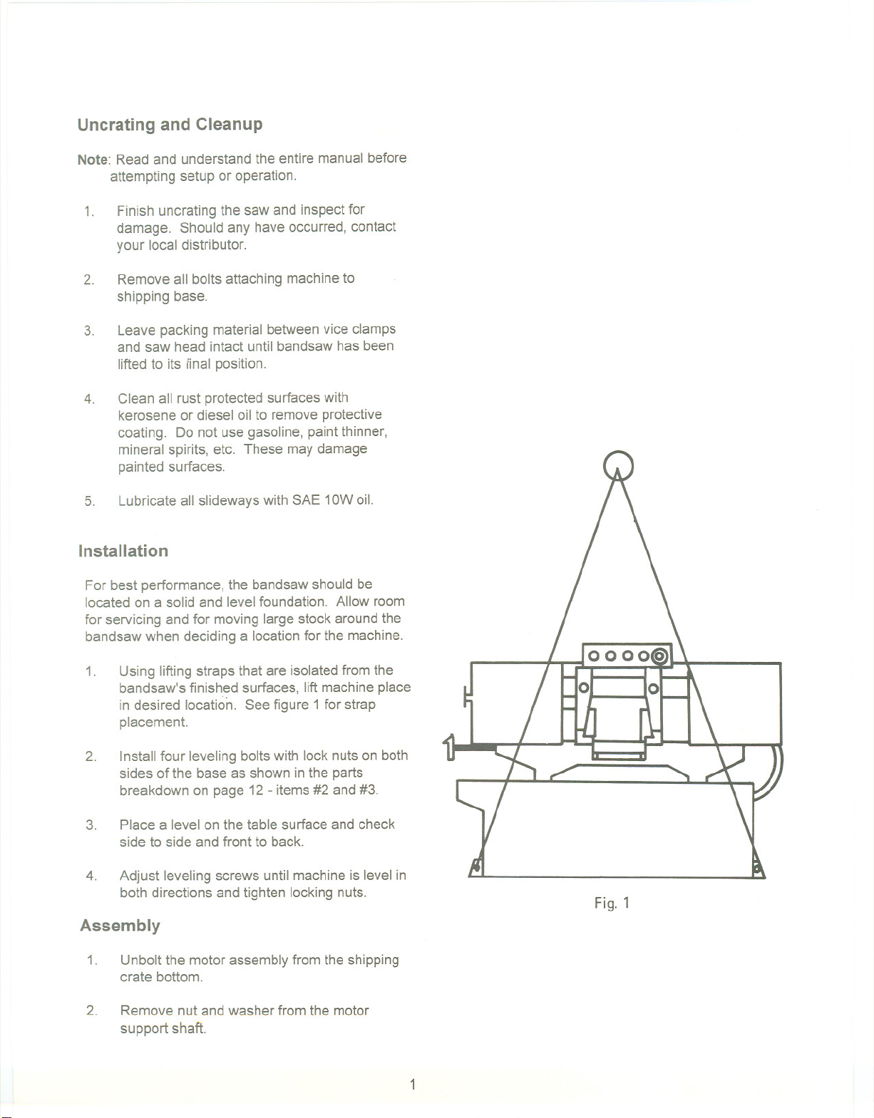
1.
Using lifting straps that are isolatedfrom the
bandsaw's finished surfaces, lift machineplace
in desired location. See figure 1 for strap
placement.
2.
Install four leveling bolts with lock nuts on both
sides of the baseas shown in the parts
breakdown on page 12- items #2 and#3.
3. Place a level on the table surface and check
side to side and front to back.
4.
Adjust leveling screws until machineis level in
both directions and tighten locking nuts.
Assembly
1.
Unbolt the motor assembly from the shipping
crate bottom.
Fig. 1
2. Remove nut and washer from the motor
support shaft.
1
Page 6
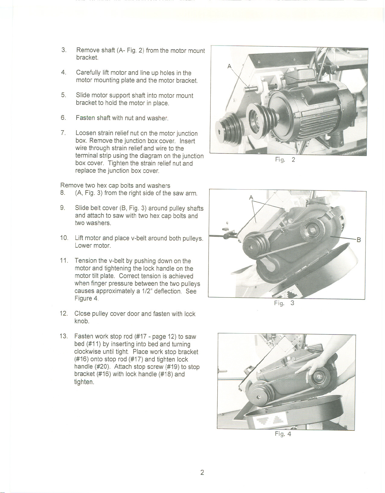
3.
Remove shaft (A- Fig. 2) from the motor mount
bracket.
4.
Carefully lift motorand line up holes in the
motor mounting plate and the motor bracket.
5.
Slide motor support shaft into motor mount
bracket to hold the motor in place.
6.
Fasten shaft with nut and washer.
7.
Loosen strain relief nuton the motorjunction
box. Removethe junction boxcover. Insert
wire through strain reliefand wire to the
terminal strip using the diagram on the junction
box cover. Tighten the strain relief nutand
replace thejunction box cover.
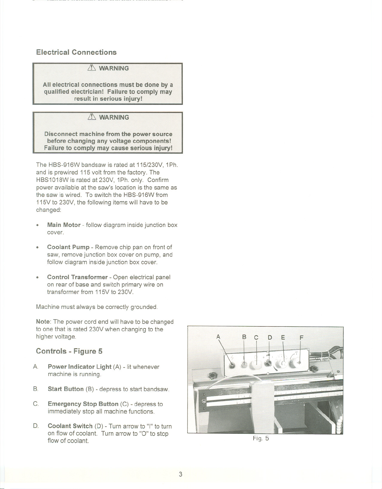
Remove two hexcap bolts and washers
8. (A, Fig. 3) from the right side of the saw arm.
9.
Slide belt cover (8, Fig.3) around pulleyshafts
and attach to saw with two hex cap boltsand
two washers.
Fig. 2
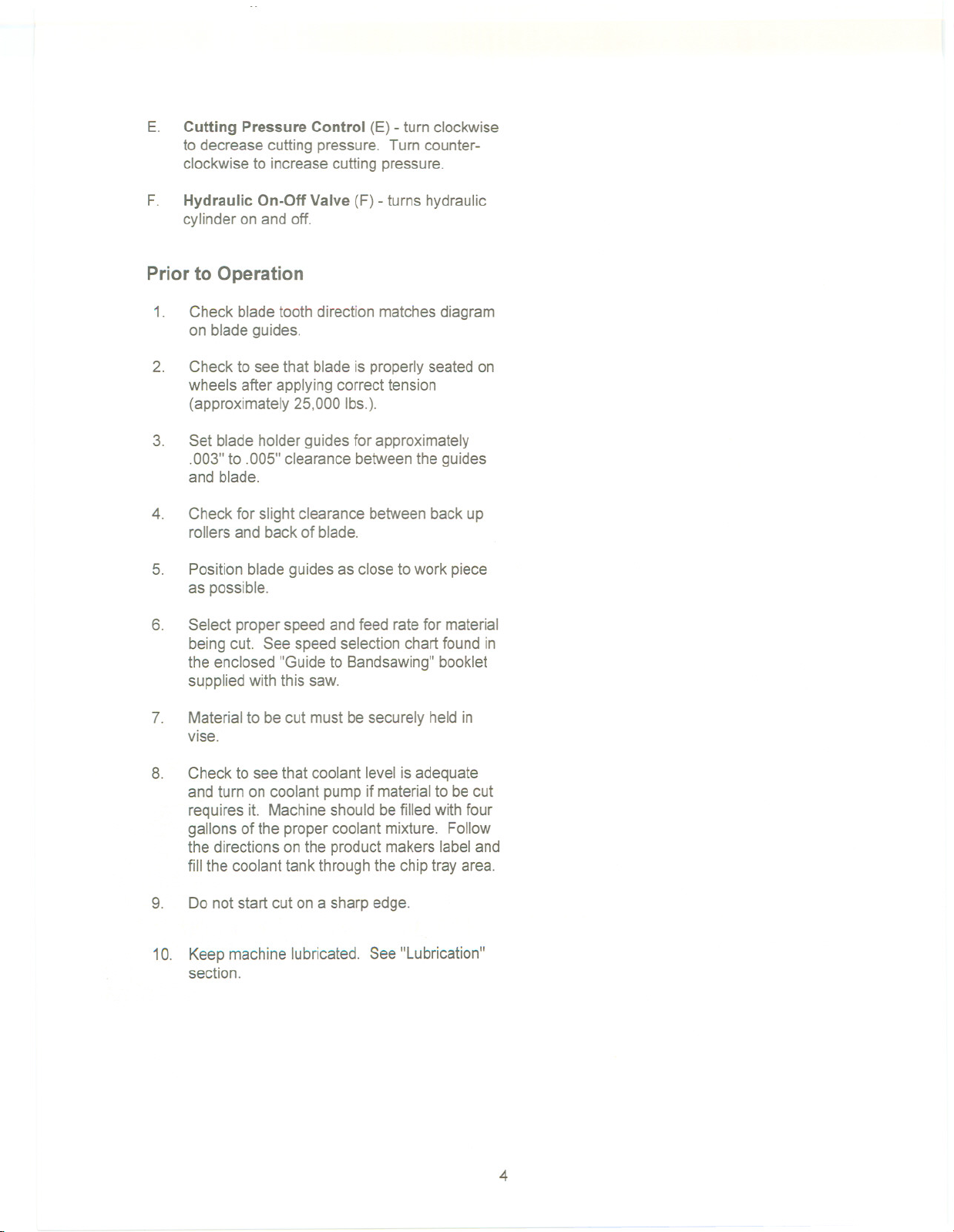
10. Lift motor and place v-belt around both pulleys.
Lower motor.
11. Tension the v-belt by pushing down on the
motor and tightening the lock handleon the
motor tilt plate. Correct tension is achieved
when finger pressure between the two pulleys
causes approximatelya 1/2"deflection. See
Figure4.
12. Close pulley cover door andfasten with lock
knob.
13. Fasten work stop rod(#17 - page 12)to saw
bed (#11) by inserting into bed and turning
clockwise until tight. Placework stop bracket
(#16) onto stop rod (#17)and tighten lock
handle (#20). Attach stop screw (#19)to stop
bracket (#16) with lock handle (#18) and
tighten.
Fig. 3
Fig. 4
2
Page 7
Electrical Connections
it WARNING
All electrical connections must be done by a
qualified electrician! Failure to comply may
result in serious injury!
it WARNING
Disconnect machine from the power source
before changing any voltage components!
Failure to comply may cause serious injury!
The HBS-916W bandsaw is rated at 115/230V,1Ph.
and is prewired 115 volt from the factory. The
HBS1018Wis rated at 230V, 1Ph.only. Confirm
power available at the saw's location is the same as
the saw is wired. To switch the HBS-916Wfrom
115Vto 230V, the following itemswill have to be
changed:
.
Main Motor - follow diagram insidejunction box
cover.
.
Coolant Pump - Removechip pan on front of
saw, removejunction boxcover on pump,and
follow diagram inside junction box cover.
.
Control Transformer - Open electrical panel
on rear of base and switch primarywire on
transformer from 115Vto 230V.
Machine must always be correctly grounded.
Note:The powercord end will have to be changed
to one that is rated 230V when changing to the
highervoltage.
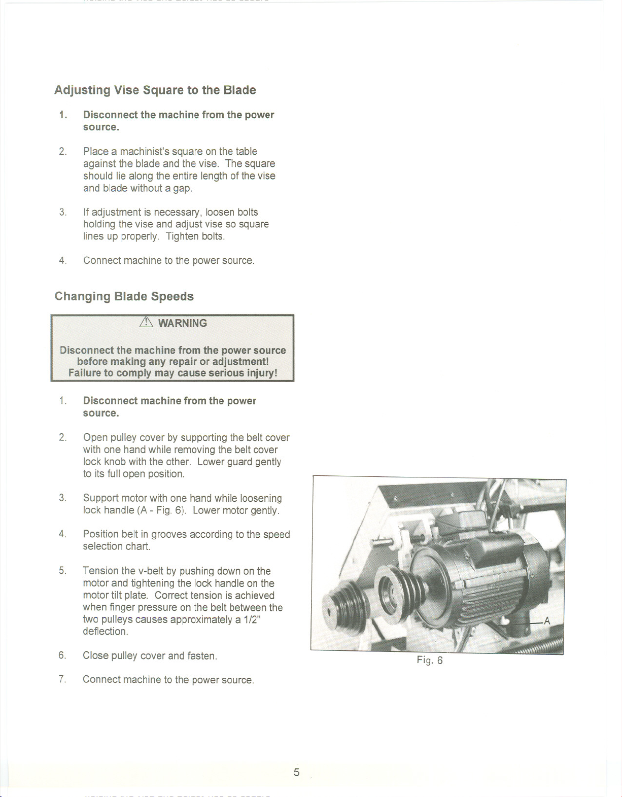
Controls - Figure 5
A.
Power Indicator Light (A) - lit whenever
machine is running.
B.
Start Button (B) - depress to start bandsaw.
C.
Emergency Stop Button (C) - depress to
immediately stop all machine functions.
o.
Coolant Switch (0) - Turn arrowto "I" to turn
on flow of coolant. Turn arrow to "0" to stop
flow of coolant.
Fig. 5
3
Page 8
E.
Cutting PressureControl (E) - turn clockwise
to decrease cutting pressure. Turn counter-
clockwise to increasecutting pressure.
F.
Hydraulic On-Off Valve (F) - turns hydraulic
cylinder on and off.
Prior to Operation
1.
Check blade tooth direction matchesdiagram
on blade guides.
2.
Check to see that blade is properlyseated on
wheels after applying correct tension
(approximately25,000 Ibs.).
3.
Set blade holder guides for approximately
.003"to .005" clearance betweenthe guides
and blade.
4.
Check for slight clearance between back up
rollers and back of blade.
5.
Position blade guides as close to work piece
as possible.
6.
Select proper speed and feed ratefor material
being cut. See speed selectionchart found in
the enclosed "Guide to Bandsawing" booklet
supplied with this saw.
7.
Material to be cut must be securely held in
vise.
8.
Check to see that coolant level is adequate
and turn on coolant pump if materialto becut
requires it. Machine should be filledwith four
gallons of the proper coolant mixture. Follow
the directions on the product makers label and
fill the coolant tank through the chip tray area.
9.
Do not start cut on a sharp edge.
10. Keepmachinelubricated. See "Lubrication"
section.
4
Page 9
Adjusting Vise Square to the Blade
1.
Disconnect the machine from the power
source.
2.
Place a machinist's square on the table
against the bladeand the vise. The square
should lie along the entire lengthof the vise
and blade without a gap.
3.
If adjustment is necessary, loosen bolts
holding the vise and adjust vise so square
lines up properly. Tighten bolts.
4.
Connect machine to the powersource.
Changing Blade Speeds
it. WARNING
Disconnect the machine from the power source
before making any repair or adjustment!
Failure to comply may cause serious injury!
1.
Disconnect machine from the power
source.
2.
Open pulley cover by supporting the belt cover
with one hand while removingthe belt cover
lock knob with the other. Lowerguard gently
to its full open position.
3.
Support motor with one hand while loosening
lock handle (A - Fig. 6). Lower motor gently.
4.
Position belt in grooves accordingto the speed
selection chart.
5.
Tension the v-belt by pushingdown on the
motor and tightening the lock handle on the
motor tilt plate. Correct tension is achieved
when finger pressure on the belt betweenthe
two pulleys causes approximately a 1/2"
deflection.
6.
Close pulley cover and fasten.
7.
Connect machine to the powersource.
Fig. 6
5
Page 10
Adjusting Feed Rate
Rateof feed is adjusted by turning the cutting
pressure control knob on the control panel. Rate of
feed is important to bandsaw performance;
excessive pressure may break the bladeor stall the
saw. Insufficient pressure rapidly dulls the blade.
Materialchips or shavings are the best indicatorof
proper speed and pressure. The idealchip is thin,
tightly curled, and warm to the touch. Chips that
range from golden brown to black indicate
excessive force. Blue chips indicateextreme heat
from too high a bandspeed which will shorten blade
life. Thin or powderedchips indicateinsufficient
feed pressure.
A detailed explanation on feed ratecan be found in
the enclosed "Guide to Band Sawing" published by
American Saw and ManufacturingCompany.
Reprinted by permission.
Changing Blades
it. WARNING
Disconnect machine from the power source
before making any adjustments or repairs!
Failure tQ comply l1'1ayresult in serious injury!
1.
Disconnect machine from power source.
2.
Raise saw arm approximately6". Hold saw
arm in place by closing cutting pressure
control valve. Remove screw (#145),
washer(#146), and brush (#147)from the wire
brush post (#148) as shown on page 13.
3.
Open bothwheel covers and clean chips out
of bothwheel housings. Loosentwo lock
knobs and remove upper bladeguard.
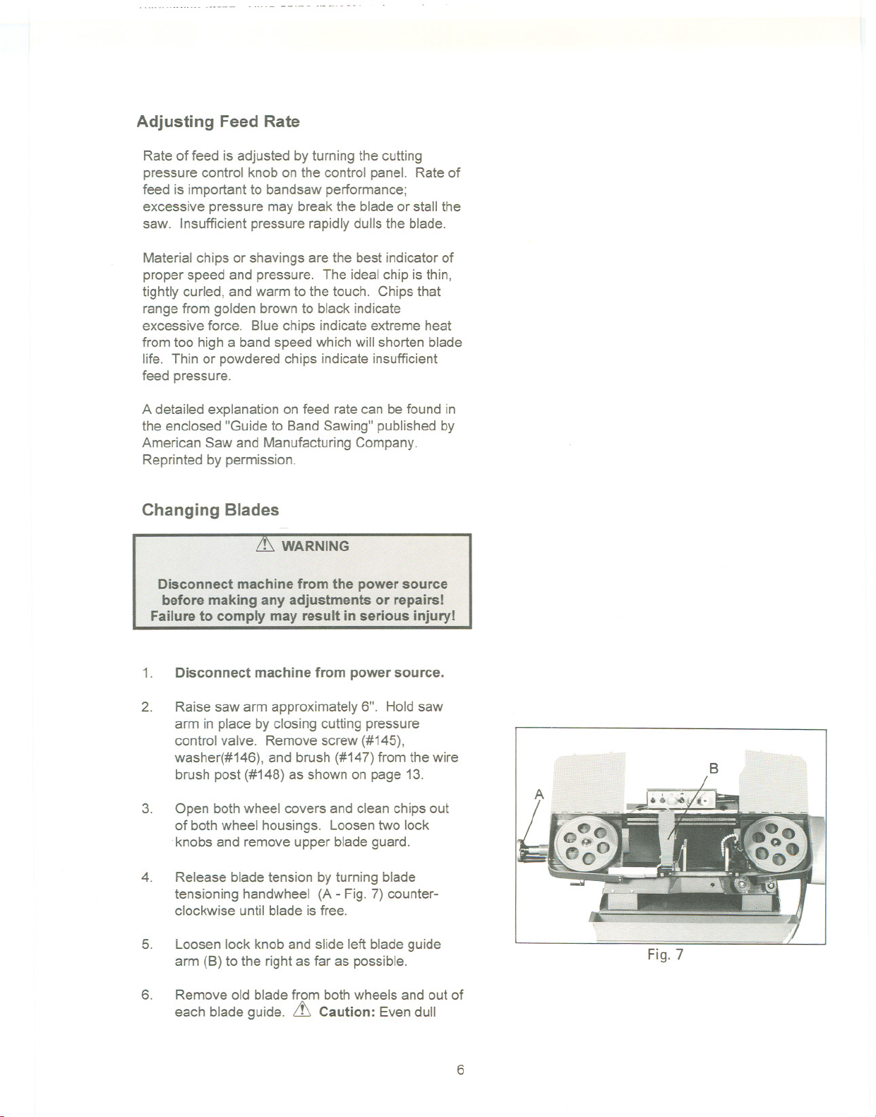
4.
Release blade tension by turning blade
tensioning handwheel (A - Fig.7)counter-
clockwise until blade isfree.
5.
Loosen lock knob and slide left blade guide
arm (B) to the right as far as possible.
B
Fig. 7
6.
Remove old bladefrom bothwheels and out of
each blade guide. it Caution:Even dull
6
Page 11

blades are sharp to the skin! Use extra
caution handling bandsawblades!
7.
Install new blade makingsure teeth are
pointed downward in the proper cutting
direction. If necessary, turn bladeinside out.
8.
Position bladeon bandwheels and tightenjust
enough to holdblade on wheels. Make sure
back of blade rests lightlyagainst the wheel
flange of bothwheels. Twist blade slightly to
allow it to slip into guides.
9.
Tension blade to approximately 25,000 Ibs. of
blade tension, as indicatedon the blade
tension indicator found on the tensionwheel
shaft housing.
10. Attach wire brush to the wire brush postwith
screw and washer. Adjust wire brush postso
that brushjust comes into contactwith blade
teeth.
11. Close all covers and guards and fasten
securely. Connect machineto power and run
freely for approximately two minutes.
12. Turn power off and re-check blade tensionand
wire brush adjustment. If further adjustmentis
necessary, disconnect saw from power
source, make adjustments, and re-connectto
power.
Blade Tracking Adjustment
Blade tracking has been set at the factory and
should require no adjustment. If a tracking problem
occurs, adjust the machine as follows:
~ WARNING
Tracking adjustment is done with the wheel
covers open to observe the blade. Use extreme
caution so as not to come into contact withthe
blade!
Since tracking can only be adjustedwhile machine
is running, it is suggested that this adjustmentbe
accomplished by qualified personnelthat are
familiar with this type of adjustmentand the dangers
associated with it.
'7
Page 12

1.
Disconnect machine from the power
source.
2.
Raise saw arm to its highest position and
close cutting pressure control valve to hold
saw arm in place.
3.
Locate tracking adjustment plate on the back
side of the driven blade wheel.
4.
Loosen the three bolts (A - Fig. 8) locatedon
the top of the tracking nuts.
5.
Tracking adjustment is accomplished by either
looseningor tighteningthree adjusting nuts
(B - Fig.8).
6.
Tracking is set properly when the back of the
blade lightly touches the wheel flange. Note:
over-tracking (allowing blade back to rub hard
against wheel flange)will damage the blade
wheels and blade.
7.
Tighten locking bolts (A) once properly
tracking is completed.
8.
Connect machine to the power source.
Automatic Shut-Off Adjustment
The motor should shut off immediatelyafter the
blade has cut through the materialandjust before
the head comes to rest on the horizontalstop bolt.
If the machine continuesto runafter the work piece
has been fully cut, locateand adjust the micro
switch mounting plate down. If the machineshuts
off before the work piecehas been completelycut,
move the micro switch mounting plate up.
Thrust Roller Adjustment
1.
Disconnect machine from the power
source.
2.
Loosen two hex socket cap screws (A - Fig.
9). Note: Left guide roller has two hexsocket
cap screw; right guide roller has one (HBS-
916Wonly) The HBS-1018Whas two
screws on each guide..
3.
Move guide seat (B) up or down untila
clearance of .003"to .005" between back of
blade and thrust roller is obtained.
Fig. 9
8
Page 13

4.
Tighten two hex socket cap screws (A).
5.
Repeat for other blade guideassembly.
6.
Connect machineto power source.
Guide Roller Adjustment
1.
Disconnect machine from the power
source.
2.
Loosen blade guides (A - Fig. 10) by loosening
screws (B). Slide blade guides away from
blade.
3.
Loosen locking screws (C) by usinga hex
wrench.
4.
Adjust the eccentric bushingswith a
combination wrench until the ball bearingsare
snug to the blade. Note: bladeshould travel
freely up and down betweenthe ball bearings.
Do not pinch the blade.
5.
Tighten locking screws (C).
6.
Slide blade guides back into contact with blade
and tighten screws (B).
7.
Connect machineto the power source.
Bow Weight Adjustment
Bowweight is one of the most important
adjustments of the saw. Ifthe bow weight is not set
properly, one can expect poor performance,
crooked cuts, tooth stripping, stalling, andthe blade
popping off the bladewheels. The hydraulicfeed
rate unit will not compensatefor improper bow
weight. Bow weight has beenset at the factory and
should not need any adjustment. If adjustment is
necessary:
guideseat
B
A
Fig. 10
1.
Disconnect the machine from the power
source.
2.
Turn hydraulic valve to on (F - Fig. 5)
3.
Turn cutting pressure control valve (E - Fig.5)
counter-clockwise until it stops.
9
Page 14

1.
Place one end of a fish-type scale under the
blade tension handle and lift the saw with the
other end. The scale should indicate
approximately 18-20 Ibs.for the HBS-916W.
For the HBS-1018W, it should indicate 22-24
Ibs.
2.
Adjust tension to approximately 18-20 Ibs.(or
22-24 Ibs.) by turning the adjustable C-bolt
found at the end of the coil spring on the rear
of the bandsaw.
3.
Connect the machine to the power source.
Vise Adjustment
To position the moveable visejaw:
1.
Turn vise handwheel (A - Fig. 11) 1/2 turn
counter-clockwise.
2.
Move rack block (B - Fig. 11) to desired
location by sliding along the bed. Placethe
rack block onto the rack.
3.
Turn the handwheel to tighten the vise.
To adjust the vise for angle cutting:
1. Loosen bolts and move visejaw (C-Fig11) to
desired location.
2. Set the vise to desired angle, reinstall nuts and
Tighten the nut and bolt assemblies.
3.
Adjust the movable vise parallel to the fixed
vise by loosening bolt (D-Fig.11) adjustingto
parallel and tightening bolt.
Maintenance
c
Keepthe band saw and the motor clean.
Lubrication
All ball bearings are permanently lubricated and
sealed. They require no further lubrication.
The gear box lubricant should be changed after the
first 50 hours of operation. Change lubricant from
then on every 250 hours of operation.
10
Page 15

To check level of gear box lubricant, place saw arm
in down position and allow a few minutes to pass
so that oil drains down. Check level in sight glass
on side of gear casing. Correct level is the dot in
the middle of sight glass.
To change gear box lubricant:
1.
Disconnect machine from the power source.
2.
Open drain plug and allow lubricant to drain
completely. Drain plug may be found on lower
front of gear case under right wheel cover.
Remove drain plug with a hex wrench.
3.
Replace drain plug.
4. Remove filler cap (A - Fig. 12) and fill gear box
with Mobil DTE@ Oil Heavy Medium until level
reaches dot in middle of sight glass.
5.
Replace filler cap.
6.
Connect machine to the power source.
Use a light machine oil to lubricate all other moving
parts as needed
A detailed explanation on blade selection and
blade problems and their solutions can be found in
the enclosed "Guide to BandSawing" published by
American Saw and Manufacturing Company. Used
by permission.
Fig. 12
11
Page 16

/'
<t"
/
~
:c
E
Q)
en
en
<
"C
Q)
[Q
"C
C
ns
Q)
I/)
ns
[Q
73
69-( ---~ Ii 0
I
2~
~.
203
12161-
~
-1 201
,_./'-~ 202
W)JiJJ~
N
......
Page 17

~
.c
E
CD
1/1
1/1
<
E
'-
<
~
nI
tn
111
121(3)
T/6 ,.,
122
175111J:IJ
~
111
8~
('f)
~
&
~i"" 9O(" )
Page 18

171,
107 .~
1084010914) 110
<1(
"
0 ~ ~'
;;
O9-1(4 - 114
~
'.~ ~
112(41 113141
111 ',~ 12
""""
.
I
~
'~
114 )
~
/
&~
172 _/~
>
122
""'"
,
99
117
6
96-1
-80
HBS 916W
Page 19

Parts List for the HBS-916W/-1018W Bandsaws
Index Part
No. No.
1 HBS916W-01 Base (SIN8081108and lower) 1
HBS916W-01A Base (SIN8081109and higher) 1
HBS1018W-01 Base (SIN 808718and lower) 1
HBS1018W-01A Base (SIN 808719and higher) 1
2 TS-1492071 ,...Hex Cap Bolt M12x70 4
3 TS-1540081 Hex Nut M12 4
4 HBS916W-CP Coolant Pump 1
5 TS-1531051. Pan HeadScrew M6x16 2
6 TS-1551061 Lock Washer M6 2
8 HBS916W-08 Hose 1
9 HBS916W-09 CoolantGauge 1
9-1 TS-1491041 HexCap Bolt ,.M1OX30 2
9-2 TS-1540071... ""'''''''''''''''' HexNut M10 2
10 HBS916W-10 Chip Tray " 1
HBS1018W-10 Chip Tray " 1
11 HBS916W-11 Bed(SIN 8081108and lower) 1
HBS916W-11A Bed(SIN 8081109and higher) 1
Description
HBS1018W-11 Bed(SIN808718andlower) " 1
HBS1018W-11A Bed (SIN808719 and higher) 1
12 TS-1490051 HexCap BoiL M8x30 8
13 TS-1550061 Washer. """""'"'''''''''''''''''''''''''''''''''''''''''''''' M8 8
14 TS-1551081 LockWasher M8 8
15 TS-1540061 HexNut M8 8
16 HBS916W-16 Stop Bracket 1
17 HBS916W-17 Stop Rod 1
18 HBS916W-18 Lock Handle 1
19 HBS916W-19 Work Stop 1
20 HBS916W-20 Lock Knob 1
21 HBS916W-21 HandWheel Assembly 1
HBS1018W-21 HandWheel Assembly 1
22 HBS916W-22 Lead Screw Seat 1
HBS1018W-22 LeadScrew Seat 1
23 TS-1490051 HexCap BoiL M8x30 2
23-1 TS-1551061 Lock Washer M8 " 2
23-2 TS-1550061 Washer M8 2
24 HBS916W-24 Lead Screw (SIN 8081108and lower) 1
HBS916W-24A LeadScrew (SIN 8081109and higher) 1
HBS1018W-24 LeadScrew (SIN 808718and lower) 1
HBS1018W-24A LeadScrew (SIN 808719and higher) 1
30 HK-2516-2RS NeedleBearing 2
31 HBS916W-31 TorsionSpring '''''''''''''''''''''''''''''''''' 1
HBS1018W-31 Torsion Spring 1
32 HBS916W-32 PivotShaft 1
32-1 TS-1550041. Washer "'''''''''''''''''''''''''''''''''''''''''''''''''''''''''' M12 2
32-2 HBS916W-32-2 BoltwI Zerk Fitting 2
33 HBS916W-33 Pivot Bracket '''''''''''''''''''''''''''''''''' 1
HBS1018W-33 Pivot Bracket 1
Size
Qty.
15
Page 20

34 TS-1540081 Nut M12 1
35 TS-1550081 Washer , M12 1
36 TS-1492041 HexCap Bolt M12x40 1
37 HBS916W-37 TorsionSpring Shaft 1
38 HBS916W-38 C-Ring S-22 1
39 TS-1490041 Hex Cap Bolt M8x25 1
39-1 TS-1551081 LockWasher M8 1
39-2 TS-1550061 Washer M8 1
40 HBS916W-40 MotorTilt Plate 1
HBS1018W-40 " MotorTilt Plate 1
41 HBS916W-41 LimitSwitch Plate 1
42 TS-1550061 Washer M8 2
43 TS-1490031 HexCap Bolt M8x20 2
43-1 ,TS-1551081 LockWasher M8 2
44 TS-1482021 Hex Cap Screw M6x12 4
44-1 TS-1441041 Washer M6 4
45 HBS916W-45 LimitSwitch 1
47 HBS916W-47.." Cylinder Pin 1
" HBS1018W-47A Cylinder Pin 1
48 HBS916W-48 C-Ring S-20 1
49 HBS916W-49 C-Ring S-25 2
50 TS-1491041 Hex Cap Bolt M10x30 1
50-1 TS-1540071 Hex Nut M10 1
51 HBS916W-51 HydraulicCylinderAssembly 1
HBS1018W-51 HydraulicCylinder Assembly 1
52 HBS916W-52 CylinderPin 1
52-1 HBS916W-52-1 , Pin 1
53 HBS916W-53 " Hydraulic MountingPlate- Top " 1
HBS1018W-53 HydraulicMountingPlate- Top 1
53-1 TS-1551071 LockWasher M10 2
53-2 TS-1491041 Hex Cap Bolt M1Ox30 2
54 TS-1492051 HexCap Bolt M12x50 2
55 ". TS-1550081 Washer... " M12 2
56 HBS916W-56 Plate " 1
57 TS-0561051 Hex Nut 1/2" 2
58 HBS916W-58. SpringBracket 1
59 HBS916W-59 ,...AdjustableC-Bolt 1
60 HBS916W-60 " Spring 1
HBS1018W-60 , Spring 1
61 HBS916W-61 AngleScale 1
62 TS-1492041 Hex Cap BoiL M12x40 2
63 TS-1551081 LockWasher M12 1
63-1 TS-1550081 Washer , M12 2
64 HBS916W-64 ViseJaw -left " 1
65 T8-1492051 HexCapBolt M12x50 , 1
66 TS-1551081 " LockWasher M12 1
66-1 TS-1550081 Washer M12 1
67 ., HBS916W-67 .. , Vise Jaw - right 1
68 TS-1492041 Hex Cap Bolt M12x40 1
68-1 TS-1551081 Lock Washer M12 1
69 TS-1503011 HexSocket Cap Bolt M6x8 4
69-1 ,HBS916W-69-1 , Nut M6 1
70 HBS916W-70 , Electrical Panel Cover (SIN 8081108 and lower HBS-916W) 1
HBS916W-70 " Electrical Panel Cover (SIN 808718 and lower HBS-1018W) 1
16
Page 21

HBS916W-70A ElectricalPanelCover (SIN8081109 and higher HBS-916W) 1
HBS916W-70A ElectricalPanelCover (SIN 808719 and higher HBS-1018W) 1
71 HBS916W-71 Fuse Block 2
HBS916W-71A Fuse 3A .. .. , 1
72 HBS916W-72B MagneticSwitch ".. 1
HBS1018W-72 MagneticSwitch 1
HBS916W-72-1 Contactor(main motor) 1
HBS916W-72A-1 , Overload Relay " 1
HBS916W-72A-2 Contactor (pump) " 1
73 HBS916W-73A Transformer , , 1
HBS1 018W-73 Transformer " 1
74 HBS916W-7 4 ".. Terminal Strip 1
75 HBS916W-75 Handle " 1
76 TS-1534051 Pan Head Screw M6x16 4
77 . TS-1482021 Hex Cap Bolt M6x12 2
77-1 TS-1551 041 Lock Washer M6 2
77-2 TS-1550041 , Washer M6 2
78 HBS916W-78 Wire Brush Guard " 1
79 TS-1503011 Hex Socket Cap Screw M6x8 12
HBS1018W-79A Adjustable Bracket Mount - rear (1018W only - not shown) 1
80 HBS916W-80 Blade Wheel Cover - right 1
HBS1018W-80A Blade Wheel Cover - righL 1
81 TS-1550041 Washer M6 4
82 HBS916W-82 . Bushing 1
83 HBS916W-83 Washer 1
84 HBS916W-84 Drive Wheel 1
HBS1 018W-84A Drive Wheel 14" 1
85 , Blade (local purchase - 916W) 1
" Blade (local purchase - 1016W) , , 1
86 HBS916W-86 Hose .." 1
87 TS-1533031 Pan Head Screw M5x10 " 2
88 HBS916W-88 Filter Screen 1
89 TS-1492031 Hex Cap BoiL M12x35 4
89-1 TS-1551 081 Lock Washer M12 4
90 HBS916W-90 Lock Knob 4
91 HBS916W-91 .." Hinge Pin 2
92 HBS916W-92 " Blade Wheel Box - right " 1
HBS1018W-92 Blade Wheel Box - right 1
93 HBS916W-93 , Connector ".. 1
HBS1 018W-93 , Connector ".. 1
94 HBS916W-94 Gear Box Assembly (can only order entire assembly) 1
HBS1018W-94 ,Gear Box Assembly (can only order entire assembly) 1
95 HBS916W-95 Key .., 7MM , 1
96 HBS916W-96 Pulley Cover , 1
HBS1 018W-96 ".. Pulley Cover " 1
96-1 HBS916W-96-1 Lock Knob 1
97 HBS916W-97 Gear Box Pulley 1
HBS1 018W-97 Gear Box Pulley 1
98 VB-A39... V-Belt 1
VB-A37 V-Belt " 1
99 HBS916W-99 Motor Pulley " 1
HBS1018W-99 Motor Pulley 1
100 TS-1482031 Hex Cap BoiL M8x16 2
100-1 ...TS-1550061 Washer M8 2
17
Page 22

100-2... TS-1551 061 Lock Washer M8 ""'"'''''''''''''''''''''' 2
101 HBS916W-1 01 .. Hose 1
101-1 ...HBS916W-1 01-1 Hose """"""""""""""""""""""""""" 1
102 """ HBS916W-1 02 Support Shaft """'"'''''''''''''''''''' 1
102-1 ...TS-1550081 Washer "'''''''''''''''''''''''''''''''''''''''''''''''''''''''''' M12 1
102-2... TS-1540081 Hex Nut M12 1
103 TS-1492021 Hex Cap BoiL M12x30 2
104 HBS916W-104 MotorMountBracket """""""'''''''''''''''''''' 1
105 HBS916W-1 05 Column... """""'''''''''''''''''''''''''''''''''''''''''''''''' 1
HBS1018W-105A Column """"'''''''''''''''''''''''''' 1
106 TS-1506011 HexSocket Cap Screw M12x20 6
107 HBS916W-107 Locking Handle """"'''''''''''''''''''''''''''''''''''''''' 1
108 TS-1550061 Washer "'''''''''''''''''''''''''''''''''''''''''''''''''''''''''' 8MM 1
109 TS-1490081 Hex Cap .Bolt M8x45 4
109-1 ...TS-1550061 Washer ""'''''''''''''''''''''''''''''''''''''''''''''''''''''''' M8"""""'"'''''''''''''''' 4
110 HBS916W-110 MotorMount Plate """"'''''''''''''''''''''''''' 1
111 HBS916W-111 Motor(1-1/2 HP, 1Ph, 115/230V) 1
HBS1018W-111 Motor (2 HP, 1Ph,230V only) 1
HBS916W-600250 Capacitor(not shown) 1
HBS916W-111-2 CapacitorCover (not shown)'"'''''''''''''''''''''''' """""""'''''''''''''''''''' 1
HBS1018W-111-1 Capacitor(not shown) 1
HBS1018W-111-2 CapacitorCover (notshown) 1
112 TS-1550061 Washer M8. """'''''''''''''''''''''' 4
112-1 ...TS-1551061 LockWasher M8 4
113 TS-1540061 Hex Nut M8 4
114 HBS916W-114 Key 7MM 1
115 TS-1550081 Washer M12 1
116 TS-1504041 HexSocket Cap Screw M8x20 1
117 HBS916W-117 BladeWheel Cover -left """""'''''''''''''''''''''''' 1
HBS1018W-117A BladeWheel Cover - left 1
118 BB-608W Ball Bearing 2
119 TS-1492011 Hex Cap BoiL M12x25 2
120 TS-1550081 Washer M12 1
121 BB-6205Z Ball Bearing 3
122 HBS916W-122 IdlerWheel 1
HBS1018W-122A IdlerWheel. . 1
123 HBS916W-123 BladeGuard """""""'''''''''''''''''''' 1
HBS1018W-123A BladeGuard 1
123-1...TS-1550061 Washer """"""""""""""""""""""""""" M8 1
123-2...TS-1551061 LockWasher M8 1
123-3...TS-1490021 HexCap Bolt M8x16 1
124 HBS916W-124 GuideBracket -left 1
HBS916W-124A Guide BracketAssembly -left 1
HBS1018W-124A Guide BracketAssembly -left 1
124-1...TS-1504031 HexSocketCapScrew(HBS-916W) M8x16 3
TS-1504031 Hex Socket Cap Screw(HBS-1018W) """"'''' M8x16 6
125 TS-1540061 Washer M8 4
126 BB-6201W Ball Bearing 8
127 HBS916W-127 EccentricSleeve (outside) (HBS916W) 2
HBS1018W-127 EccentricSleeve(outside)(HBA1018W)... 2
127-1 HBS916W-127-1 Sleeve (inside-notshow) (HBS916W) 2
.HBS1018W-127-1 Sleeve(inside-not show) (HBS1018W) 2
18
Page 23

128 TS-1551061.. LockWasher.... "... M8 4
129 TS-1504091 Hex Socket Cap Screw M8x45 4
130 TS-1503071 Hex Socket Cap Screw M6x30 4
130-1...TS-1550041 Washer M6 8
131 HBS916W-131 Blade Guide , 4
132 TS-1504081 HexSocket Cap Screw (HBS-916W) M8x40 2
TS-1504081 HexSocket Cap Screw (HBS-1018W) M8x40 4
133 TS-1551081 LockWasher (HBS-916W) M8 2
TS-1551081 LockWasher (HBS-1018W) M8 4
133-1...TS-1550081... Washer(HBS-916W) M8 2
. TS-1550081... Washer(HBS-1018W) M8 4
134 HBS916W-134 AdjustableBracket , 1
HBS1018W-134A Adjustable Bracket 1
135 HBS916W-135 Scale (1018W) 1
HBS1018W-135 DovetailScale 1
136 TS-1505031 Hex Socket Cap Screw M10x25 2
137 HBS916W-137 Slide 1
HBS1018W-137A Slide ".. 1
138 HBS916W-138 " Blade Bracket -left , 1
HBS1018W-138 Blade Bracket -left ..., 1
139 TS-1492021. Hex Cap Bolt M12x30 4
139-1...TS-551081 LockWasher M12 4
140 TS-1490041 HexCap Bolt (HBS-916W) M8x25 2
140-1...TS-1551061 LockWasher (HBS-916W) , M8 2
141 HBS916W-141 Knob """""'"'''''''''''''''''''''''''''''''''''''''''''' 1
HBS1018W-141 Knob 1
142...". HBS916W-142 Plate... ". 1
143 TS-1524021 Set Screw M8x10 4
144 HBS916W-144 Blade Bracket - right 1
HBS1018W-144 BladeBracket- right ,..1
145 TS-1482011 HexCap Bolt M6x10 1
146 TS-1550041 Washer M6 1
147 HBS916W-147 Wire Brush " 1
HBS1018W-147 Wire Brush 1
148 HBS916W-148 Wire Brush Rod " 1
HBS1018W-148 Wire Brush Rod " " 1
149 HBS916W-149 Guide Bracket- right 1
HBS1018W-149 , Guide Bracket- right ..." 1
HBS916W-149A Guide BracketAssembly - right 1
HBS1018W-149A Guide BracketAssembly- right 1
150 HBS916W-150.."'''''''''''''' Spring 1
HBS1018W-150 Spring 1
152 TS-1540071 Hex Nut M10 1
153 TS-1504091 HexSocket Cap Screw (HBS-916W) M8x45 2
153-1...HBS916W-153-1 Hex Socket Cap Screw M8x55 1
154 HBS1018W-154A Adjustable Bracket- right (HBS-1018W) 1
155 TS-1540081 Hex Nut M12 1
156""" TS-1492061... Hex Cap Bolt M12x60 1
157 HBS916W-157 Blade Guard 1
HBS1018W-157A BladeGuard " 1
157-1...HBS1018W-157-1 Blade Guard- down 1
158 HBS916W-158 Lock Knob """""""'''''''''''''''''''' 1
159 TS-1523021 Set Screw (HBS-1018W) M6x8 1
160 HBS916W-160 AdjustingValve 2
19
Page 24

160-1 ... HBS916W-160-1 Clamp 1
160-2 ...TS-1551 041 Lock Washer M6 4
160-3... TS-1482021 Hex Cap Bolt M6x12 4
161 HBS916W-161A PowerIndicator Light ""'''''''''''''''''''''''''''''' 1
162 HBS916W-162 StartSwitch 1
163 HBS916W-163""'''''''''''''' Stop Switch 1
164 HBS916W-164 PumpSwitch 1
165 HBS916W-165S FeedControl- HydraulicOn/OffValve """""" 1
HBS916W-165S-1 Speed ControlValve 1
HBS916W-165S-1-K Knob for Speed ControlValve ""'''''''''''''''''''''''''''''' 1
HBS916W-165S-K Knob for On/Off Valve 1
166 HBS916W-166 ConnectingTube 1
166-1...HBS916W-166-1 Hose Clamp """"""""""'''''''''''''' 3
168 HBS916W-168 ControlBox 1
169 HBS916W-169.." Control Panel 1
170 TS-1533031 Pan HeadScrew M5x10 6
171 HBS916W-171 Wheel Box -left 1
HBS1018W-171 Wheel Box-left 1
172 HBS916W-172 Handle 1
173 TS-1540081 Hex NuL M12 2
175 TS-1533031 Pan HeadScrew M5x10 2
176 HBS916W-176 IndicatorScale """"""""'''''''''''''''''' 1
177 HBS916W-177 SlideBracket """""""""'''''''''''''''' 1
178 HBS916W-178 Tension Shaft 1
179 HBS916W-179 Key 5MM 1
180 HBS916W-180 Handwheel 1
181 HBS916W-181 LockWasher M22 13
182 HBS916W-182 FlatSteelWasher 1
183 HBS916W-183 Tension Indicator 1
184 BB-51104 Thrust Bearing 1
187 HBS916W-187 Slide 1
188 TS-1524021 Set Screw M8x10 1
189 HBS916W-189 ExtensionBar 1
190 HBS916W-190 Wheel Shaft 1
191 HBS916W-191 Nutw/Hole For Set Screw M14 1
191-1...TS-1523021 Set Screw M6x8 1
192 TS-1504051 HexSocket Cap Screw M8x25 4
193 TS-1492011 HexSocket Cap Screw M12x25 1
194 HBS916W-194 Gib... 2
195 HBS916W-195 HexCap Screw (re: HBS916W-196) 3
196 HBS916W-196 ScrewAssembly 3
196-1...HBS916W-196-1 LockWasher (re: HBS916W-196) 3
197 HBS916W-197 HoseFitting 1
198 HBS916W-198 HoseClamp 1
199 HBS916W-199 HoseClamp 2
HBS1018W-199 HoseClamp 1
200 HBS916W-200 Nut 1
201 HBS916W-201 Strain ReliefFitting 1
202 HBS916W-202 PowerCord 1
203 HBS916W-203 Screw 1
204 HBS916W-204 Name Plate 1
205 HBS916W-205 Warning Label 1
206 HBS916W-206 SpeedChart Label 1
207 HBS916W-207 Hose """""""'''''''''''''''''''' 1
20
Page 25

208 HBS916W-208 Hose , 1
213 TS-1550071 Washer M10 2
214 HBS1018W-214 Clamp 2
215 ...". HBS916W-215 CuConnector 1
.. HBS1018W-215 Cu Connector 2
216 TS-1504051 Hex SocketCap Screw M8x25 2
217 HBS916W-217 SlideBracket 1
218 HBS916W-218 LeadScrewBracket 1
219 HBS916W-219 RackBlock 1
HBS1018W-219 RackBlock. 1
220 HBS916W-220 Rack 1
HBS1018W-220 Rack. 1
221 HBS916W-221 Pin 1
21
Page 26

w--~
-
-
'<
't:I
fa
:t>
tn
tn
CD
3
C"
G>
CD
Q)
""'I
C/)
CD
CD
a.
::c
CD
a.
t:
0
::s
m
0
><
+::0
u, -'jf
~~\~ ~~
+::0
-.c
\
~
oc
~--~
Page 27

Parts List For The Gear Speed Reducing Box Assembly
Index Part
No. No. Description Size Qty.
1 HBS916W-94-01 OIL .SEAL 35x55X8 1
2 HBS916W-94-02 BEARING 30207 1
3 HBS916W-94-03 BEARING 6207.. . 1
4 HBS916W-94-04 SHAFT '"'''''''''''''''''''''''''''''''''''''''''''''''''''''''' 1
5 HBS916W-94-05 KEY 8x7x30 1
6 HBS916W-94-06 GEAR WHEEL 1
7 HBS916W-94-07 BEARING 6206 1
8 HBS916W-94-08 OUTPUT SHAFT COVER 1
9 HBS916W-94-09 OUTPUT HEX CAP SCREW M10x20 4
10 HBS916W-94-10 INPUT HEX CAP SCREW "" M8x20 4
11 HBS916W-94-11 INPUT SHAFT COVER 1
12 HBS916W-94-12 WASHER 1
13 HBS916W-94-13 BEARING """"""'" 6025 1
14 HBS916W-94-14 INPUT SHAFT '"'''' 1
15 HBS916W-94-15 KEY """""'''''''' .. 7x7x60 1
16 HBS916W-94-16 BEARING 6205 1
17 HBS~16W-94-17 C-RING R52 1
18 HBS916W-94-18 OIL SEAL. ' 25x52x8.. 1
19 HBS916W-94-19 VENT BOLT... 1
20 HBS916W-94-20 ... GEAR BOX '" ..1
21 HBS916W-94-21 OIL LENS.. '" ..1
22 HBS916W-94-22 DRAW PLUG 1
23 HBS916W-94-23.. . KEY .7X7X45.. ... 4
23
Page 28

1PH
Electrical Schematic for the HBS-916W
R
AC 110/220V
s
220V
STOP
0
4 0 L
Electrical Panel Layout
Selec-Sw
Pump
5
6
0 4-1 T U,v, W, U, v, W, a 1 2 3 4 51 0
t~
R S 0 115V
115V 230V 6
R 230 0 115 , i m
TR 11OV/220V
0 0 0 0
S
U2V2
0
5
R S 2
U, V,
6
4
24
Page 29

1PH
Electrical Schematic for the HBS-1 a 18W
R
s
AC 1~
220V
2
110V
220V
STOP
Selec-Sw
Pump
0 4 a L 6
Electrical Panel Layout
0 Lt-iT U,V, w, U, v, W, 0 1 2 3 4 51 0
R S 0 115V
R 230 0 115
0 0 0 0
230V
s
u. v.
tt
6
5
U,V,
4
0
25
Page 30

Page 31

Page 32

 Loading...