


This .pdf document is bookmarked
Operation and Maintenance Instructions
Geared Head Lathes
Models GH-1340W, GH-1440W
See manual no. M-321810-1 for service parts and electrical diagrams.
JET
427 New Sanford Road
LaVergne, Tennessee 37086 Part No. M-321810
Ph.: 800-274-6848 Revision H 06/2016
www.jettools.com Copyright © 2014 JET

1.0 Warranty and service
JET warrants every product it sells against manufacturers’ defects. If one of our tools needs service or repair, please
contact Technical Service by calling 1-800-274-6846, 8AM to 5PM CST, Monday through Friday.
Warranty Period
The general warranty lasts for the time period specified in the literature included with your product or on the official
JET branded website.
• JET products carry a limited warranty which varies in duration based upon the product. (See chart below)
• Accessories carry a limited warranty of one year from the date of receipt.
• Consumable items are defined as expendable parts or accessories expected to become inoperable within a
reasonable amount of use and are covered by a 90 day limited warranty against manufacturer’s defects.
Who is Covered
This warranty covers only the initial purchaser of the product from the date of delivery.
What is Co vered
This warranty covers any defects in workmanship or materials subject to the limitations stated below. This warranty
does not cover failures due directly or indirectly to misuse, abuse, negligence or accidents, normal wear-and-tear,
improper repair, alterations or lack of maintenance. JET woodworking machinery is designed to be used with Wood.
Use of th ese ma chines in the processing of metal , pl asti cs, or oth er m aterial s may void the warranty. The exceptio ns
are acrylics and other natural items that are made specifically for wood turning.
Warranty Limitations
Woodworking products with a Five Year Warranty that are used for commercial or industrial purposes default to a
Two Year Warranty. Please contact Technical Service at 1-800-274-6846 for further clarification.
How to Get Technical Support
Please contact Technical Service by calling 1-800-274-6846. Please note that you will be asked to provide pr o of
of initia l p u rch a s e whe n calling. If a product requires further inspection, the Technical Service representative will
explain and assist with any additional action needed. JET has Authorized Service Centers located throughout the
United States. For the name of an Authorized Service Center in your area call 1-800-274-6846 or use the Service
Center Locator on the JET website.
More Information
JET is constantly adding new products. For complete, up-to-date product information, check with your local distributor
or visit the JET website.
How State Law Appli es
This warranty gives you specific legal rights, subject to applicable state law.
Limitations on This Warranty
JET LIMITS ALL IMPLIED WARRANTIES TO THE PERIOD OF THE LIMITED WARRANTY FOR EACH PRODUCT.
EXCEPT AS STATED HEREIN, ANY IMPLIED WARRANTIES OF MERCHANTABILITY AND FITNESS FOR A
PARTICULAR PURPOSE ARE EXCLUDED. SOME STATES DO NOT ALLOW LIMITATIONS ON HOW LONG AN
IMPLIED WARRANTY LASTS, SO THE ABOVE LIMITATION MAY NOT APPLY TO YOU.
JET SHALL IN NO EVENT BE LIABLE FOR DEATH, INJURIES TO PERSONS OR PROPERTY, OR FOR
INCIDENTAL, CONTINGENT, SPECIAL, OR CONSEQUENTIAL DAMAGES ARISING FROM THE USE OF OUR
PRODUCTS. SOME STATES DO NOT ALLOW THE EXCLUSION OR LIMITATION OF INCIDENTAL OR
CONSEQUENTIAL DAMAGES, SO THE ABOVE LIMITATION OR EXCLUSION MAY NOT APPLY TO YOU.
JET sells through distributors only. The specifications listed in JET printed materials and on official JET website are
given as general information and are not binding. JET reserves the right to effect at any time, without prior notice,
those alterations to parts, fittings, and accessory equipment which they may deem necessary for any reason
whatsoever. JET
Product Listing with Warranty Period
90 Days – Parts; Consumable items
1 Year – Motors; Machine Accessories
2 Year – Metalworking Machinery; Electric Hoists, Electric Hoist Accessories; Woodworking Machinery used
for industrial or commercial purposes
5 Year – Woodworking Machinery
Limited Lifetime – JET Parallel clamps; VOLT Series Electric Hoists; Manual Hoists; Manual Hoist
Accessories; Shop Tools; Warehouse & Dock products; Hand Tools; Air Tools
NOTE: JET is a division of JPW Industries, Inc. References in this document to JET also apply to JPW Industries,
Inc., or any of its successors in interest to the JET brand.
®
branded products are not sold in Canada by JPW Industries, Inc.
2

2.0 Table of contents
Section Page
1.0 Warranty and service ..................................................................................................................................... 2
2.0 Table of contents ............................................................................................................................................ 3
3.0 Safety warnings .............................................................................................................................................. 4
4.0 Specifications ................................................................................................................................................. 5
5.0 Uncrating ........................................................................................................................................................ 6
5.1 Contents of shipping container ................................................................................................................... 6
6.0 Installation ...................................................................................................................................................... 7
6.1 Chuck preparation (three jaw) .................................................................................................................... 7
7.0 Lubrication ...................................................................................................................................................... 8
8.0 Coolant preparation ...................................................................................................................................... 10
9.0 Electrical connections .................................................................................................................................. 10
10.0 General description .................................................................................................................................... 11
11.0 Operation ................................................................................................................................................... 14
11.1 Break-in procedure ................................................................................................................................. 14
11.2 Feed and thread selection ...................................................................................................................... 15
11.3 Change gears replacement .................................................................................................................... 15
11.4 Automatic feed operation and feed changes .......................................................................................... 15
11.5 Powered carriage travel ......................................................................................................................... 16
11.6 Thread cutting ........................................................................................................................................ 16
11.7 Compound rest ....................................................................................................................................... 16
12.0 Adjustments ............................................................................................................................................... 16
12.1 Saddle .................................................................................................................................................... 16
12.2 Cross slide .............................................................................................................................................. 17
12.3 Compound rest ....................................................................................................................................... 17
12.4 Tailstock ................................................................................................................................................. 17
12.5 Tailstock off-set ...................................................................................................................................... 17
12.6 Tailstock gibs .......................................................................................................................................... 17
12.7 Headstock alignment .............................................................................................................................. 18
12.8 Removing gap section ............................................................................................................................ 18
12.9 Installing gap section .............................................................................................................................. 18
12.10 Belt replacement and adjustment ......................................................................................................... 19
12.11 Aligning tailstock to headstock ............................................................................................................. 19
13.0 Operation tables ......................................................................................................................................... 20
13.1 Metric thread table .................................................................................................................................. 20
13.2 Inch lead and feed table ......................................................................................................................... 20
Familiarize yourself with the following safety notices used in this manual:
This means that if preca utions are not heeded, it m ay result in minor injury a nd/or possible
machine damage.
This means that if precautions are not heeded, it may result in serious or even fatal injury.
3

3.0 Safety warnings
1. Read and understand the entire instruction manual before attempting assembly or operation.
2. These lathes are designed and i ntended for use by properly trained a nd experienced personnel only. If
you are not familiar with the proper and safe operation of a lathe, do not use until proper tra ining and
knowledge have been obtained.
3. Always wear approved safety glasses/face shield while using this machine.
4. Make certain the machine is properly grounded.
5. Before operating the machine, remove tie, rings, watches, other jewelry, and roll up sleeves above the
elbows. Remove all loose clothing and confine long hair. Do not wear gloves.
6. Keep the floor around the machine clean and free of scrap material, oil and grease.
7. Keep machine guards in place at all times when the machine is in use. If removed for maintenance
purposes, use extreme caution and replace the guards immediately.
8. Do not o ver reach. Maintain a balanced stance at all times so that you do not fall or lean against blades or
other moving parts.
9. Make all machine adjustments or maintenance with the machine unplugged from the power source.
10. Use the right tool. Don't force a tool or attachment to do a job for which it was not designed.
11. Replace warning labels if they become obscured or removed.
12. Make certain the main power switch is in the OFF position before connecting the machine to the power
supply.
13. Give your work undivided attention. Looking around, carrying on a conversation, and "horse-play" are
careless acts that can result in serious injury.
14. Some dust created by power sanding, sawing, grinding, drilling and other construction activities contain
chemicals known to cause cancer, birth defects or other reproductive harm. Some examples of these
chemicals are:
• Lead from lead based paint.
Crystalline silica from bricks, cement and other masonry products.
•
Arsenic and chromium from chemically treated lumber.
•
Your risk of exposure varies, depending on how often you do this type of work. To reduce your exposure to
these chemicals, work in a well-ventilated area and work with approved safety equipment, such as face or
dust masks that are specifically designed to filter out microscopic particles.
15. Keep visitors a safe distance from the work area.
16. Use recommended accessories; improper accessories may be hazardous.
17. Make a habit of checking to see that keys and adjusting wrenches are removed before turning on the
machine.
18. Never attempt any operation or adjustment if the procedure is not understood.
19. Keep fingers away from revolving parts and cutting tools while in operation.
20. Keep belt guard in place and in working order.
21. Never force the cutting action.
22. Do not attempt to adjust or remove tools during operation.
23. Always keep cutters sharp.
24. Always use identical replacement parts when servicing.
25. Never operate this machine under the influence of alcohol or drugs.
26. Failure to comply with all of these warnings may cause serious injury.
4

4.0 Specifications
GH-1340W-1 GH-1440W-1
GH-1340W-3 GH-1440W-3
Stock Number (1 Phase) ......................................................... 321810 ....................................................... 321830
Stock Number (3 Phase) ......................................................... 321820 ....................................................... 321840
Capacities:
Swing Over Bed (in.) ....................................................................... 13 ............................................................... 14
Swing Over Cross Slide (in.) ....................................................... 7-1/4 ........................................................... 8-1/4
Swing Through Gap (in.) ................................................................. 19 ............................................................... 20
Length of Gap (in.) ...................................................................... 9-3/8 ........................................................... 9-3/8
Distance Between Centers (in.) ...................................................... 40 ............................................................... 40
Headstock:
Hole Through Spindle (in.) .......................................................... 1-1/2 ........................................................... 1-1/2
Spindle Nose ............................................................................... D1-4 ............................. .............................. D1- 4
Taper in Spindle Nose .................................................................MT-5 ........................................................... MT-5
Spindle Taper Adapter ................................................................MT-3 ........................................................... MT-3
Spindle Bearing Type ......................................... Taper Roller Bearing .................................. Taper Roller Bear ing
Number of Spindle Speeds ............................................................. 12 ............................................................... 12
Range of Spindle Speeds (RPM) ........................................... 40-1800 ...................................................... 40-1800
Gearbox:
Number of Longitudinal and Cross Feeds ....................................... 40 ............................................................... 40
Range of Longitudinal Feeds (inch/rev.) ................... 0.0011 – 0.0271 ......................................... 0.0011 – 0.0271
Range of Cross Feeds (inch/rev.) ............................. 0.0003 – 0.0100 ......................................... 0.0003 – 0.0103
Number of Inch Threads ................................................................. 40 ............................................................... 40
Range of Inch Threads (T.P.I.) ................................................ 4 – 112 ....................................................... 4 – 112
Number of Metric Threads .............................................................. 22 ............................................................... 22
Range of Metric Threads (mm) ........................................... 0.45 – 7.5 ................................................... 0.45 – 7.5
Leadscrew (in.) ................................................................. 7/8 x 49-1/2 ................................................ 7/8 x 49-1/2
Feed Rod Diameter (in.) ................................................................. 3/4 ............................................................. 3/4
Compound and Carriage:
Toolpost Type ...........................................................................4-Way ................................ ......................... 4-Way
Maximum Tool Size (in.) ....................................................... 5/8 x 5/8 ..................................................... 5/8 x 5/8
Maximum Compoun d Sli de Travel (in.) ....................................... 3-1/2 ........................................................... 3-1/2
Maximum Cross Slide Travel (in.) ............................................... 6-3/8 ........................................................... 6-3/8
Maximum Carriage Travel (in.) .................................................. 37-1/2 ......................................................... 37-1/2
Tailstock:
Tailstock Spindle Travel (in.) ....................................................... 4-3/4 ........................................................... 4-3/4
Diameter of Tailstock Spindle (in.) .......................................... 1-25/32 ....................................................... 1-25/32
Taper in Tailstock Spindle ...........................................................MT-3 ........................................................... MT-3
Miscellaneous:
Steady Rest Capacity (in.) ................................................. 1/4 – 3-1/2 .................................................. 1/4 – 3-1/2
Follow Rest Capacity (in.) ................................................. 1/4 – 2-3/4 .................................................. 1/4 – 2-3/4
Length of Bed (in.) ..................................................................... 54-1/2 ......................................................... 54-1/2
Width of Bed (in.) ...................................................................... 10-1/4 .............................. ........................... 10-1/4
Height of Bed (in.) ..................................................................... 12-3/4 ......................................................... 12-3/4
Overall Dimensions (in.) .......................................... 78L x 38W x 59H ....................................... 78L x 38W x 59H
Main Motor:
1-Phase ................................................ 3HP, 1PH, 230V Only, 18A ........................ 3HP, 1PH, 230V Only, 18A
3-Phase ................................ 3HP, 3PH, 230/460V, Prewired 230V ........ 3HP, 3PH, 230/460V, Prewired 230V
.......................................................................................... 8.3/4.2A ..................................................... 8.3/4.2A
Net Weight (lbs./approx.) ........................................................... 2,081 .......................................................... 2,191
Shipping Weight (lbs./approx.) ................................................... 2,351 ...................................... .................... 2,491
The above specifications were current at the time this manual was published, but because of our policy of continuous
improvement, JET reserves the right to change specif ications at any time and without prior notice, without incurring
obligations.
5

5.0 Uncrating
Open shipping crate and check for shipping
damage. Report any damage immediately to your
distributor and shipping agent. Do not discard any
shipping material until the Lathe is assembled and
running properly.
Compare the contents of your crate with the
following parts list to make sure all parts are intact.
Missing parts, if any, should be reported to your
distributor.
Read and understand the
entire contents of this manual before
attempting set-up or operation. Failure to
comply may cause seriou s injury!
5.1 Contents of shipping container
1 Lathe
1 Steady Rest
1 Follow Rest
1 6" Three Jaw Chuck w/ Top Reversing Jaws
(Direct Mount)
1 8" Four Jaw Chuck with Backplate
1 12" Face Plate (strapped to container floor)
1 Backplate
1 Tool Box (p/n GH1440W-TBCP)
Tool Box Contents (p/n GH1440W-TBCP):
(Figure 1)
1 No. 1 Cross Point Screwdriver
1 No. 1 Flat Blade Screwdriver
4 Open End Wrench
(9-11, 10-12, 12-14, 17-19mm)
6 Hex Socket Wrench (2.5, 3, 4, 5, 6, 8mm)
2 Shear Pins
1 30T Change Gear
1 32T Change Gear
2 40T Change Gear
1 Oil Can
2 No. 3 Morse Taper Dead Center
1 No. 5 to No. 3 Spindle Sleeve
6 Leveling Pads
1 Chuck Key
1 Key for Cam Locks
1 Tool Post Wrench
1 Instruction Manual
1 Parts List Manual
1 Warranty Card
Figure 1
6

6.0 Installation
1. Finish removing the wooden crate from around
the lathe.
2. Unbolt the lathe from the shipping crate
bottom.
3. Choose a location for the lathe that is dry, has
good lighting, and has enough room to service
the lathe on all four sides
4. Place two steel rods or pipes (of sufficient
strength) into four holes (A, Fig. 2) of lathe
stand. Sling the lathe with properly rated
straps. Do not lift by spi ndle. With adequate
lifting equipment, slowly raise the lat he off the
shipping crate bottom. Make sure lathe is
balanced before moving.
5. To avoid twisting the bed, the lathe's location
must be absolutely flat and level. C heck for a
level condition using a machinist's precision
level on the bedways both front to back and
side to side. The leveling pads included in the
tool box and the leveling screws in the lathe
base will help you to reach a level condition.
The lathe must be level to be accurate.
6. Clean all rust protected surfaces using a mild
commercial solvent, kerosene or diesel fuel.
Do not use paint thinner, gasoline, or lacquer
thinner, as these can damage painted
surfaces. Cover all cleaned surfaces with a
light film of Mobil DTE® Oil Heavy Medium.
7. Open the end gear door. Clean all
components of the end gear assembly and
coat all gears with Mobilith® AW 1. Close the
door.
Figure 2
6.1 Chuck preparation (three jaw)
Read and understand all
directions for chuck preparation. Failure to
comply may cause serious injury and/or
damage to the lathe!
Note: Before removing the chuck from the spindle,
place a way board across the bedways under the
chuck
1. Support the chuck while turning three
camlocks 1/4 turn counter-clockwise with the
chuck key enclosed in the tool box.
2. Carefully remove the chuck from the spindle
and place on an adequate work surface.
3. Inspect the camlock studs. Make sure they
have not become cracked or broken during
transit. Clean all parts thoro ughly with solvent.
Also clean the spindle and camlocks.
Figure 3
7

4. Cover all chuck jaws and scroll inside the
chuck with Mobilith® AW 2. Co ver t he sp ind le,
cam locks, and chuck body with a l ight film of
Mobil DTE® Oil Heavy Medium.
5. Lift the chuck up to the spindle nose and press
onto the spindle. Tighten in place by turning
the cam locks 1/4 turn clockwise. The index
mark (A, Fig. 3) on the camlock should be
between the two indicator arrows (B, Fig. 3). If
the index mark is not between the two arrows,
remove the chuck and adjust the camlock
studs by either turning out one full turn (if
cams will not engage) or turning in one full turn
(if cams turn beyond indicator marks).
6. Install chuck and tighten in place.
7.0 Lubrication
Lathe must be serviced at all
lubrication points and all reservoirs filled to
operating level before the lathe is put into
service. Failure to comply may cause serious
damage to the lathe.
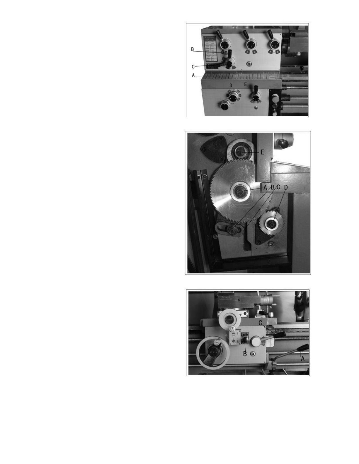
1. Headstock - Oil must be up to i ndicator mark
in oil sight glass (A, Fig. 4). Top off with Mobil
DTE® Oil Heavy Medium. Fill by pulling plug
(D, Fig. 4). To drain, remove drain plug (A, Fig.
5) with an 8mm hex wrench. Drain oil
completely and refill after the first month of
operation. Clean out any metal shavings.
Then, change oil in the headstock annually.
Figure 4
Figure 5
2. Gearbox - Oil must be up to indicator mark in
oil sight glass (B, Fig. 4). Top off with Mobil
DTE® Oil Heavy Medium. Fill by lifting off
thread chart cover (E, Fig. 4) and remove plug
(C, Fig. 4) with an 8mm hex wrench. To drain,
remove drain plug (A, Fig. 6) with an 8mm hex
wrench. Drain oil completely and refill after the
first month of operation. Then, change oil in
the Gearbox annually.
Figure 6
8
3. Apron - oil must be up to indicator mark in oil
sight glass (A, Fig. 7). Top off with Mobil
DTE® Oil Heavy Medium. Remove oil cap (B,
Fig. 7) on top of apron to fill. To drain, remove
drain plug on bottom of apron. Drain oil
completely and refill after the first month of
operation. Then, change oil in the apron
annually.
4. Leadscrew Feed Rod - lubricate ball oiler (A ,
Fig. 8) on leadscrew/feed rod bracket with
Mobil DTE® Oil Heavy Medium once daily.
5. Tailstock - lubricate two ball oilers (B, Fig. 8)
on tailstock with Mobil DTE® Oil Heavy
Medium once daily.
6. Cross Slide - lubricate four ball oilers (A, Fig.
9) with Mobil DTE® Oil Heavy Medium once
daily.
7. Compound Rest - lubricate one ball oiler (B,
Fig. 9) with Mobil DTE® Oil Heavy Medium
once daily.
8. Carriage - lubricate four ball oilers (D, Fig. 9)
with Mobil DTE® Oil Heavy Medium once
daily.
Figure 7
Figure 8
Figure 9
9

8.0 Coolant preparation
Follow coolant manufac-
turer’s recommendations for use, care and
disposal.
1. Remove rear access cover on tailstock end.
Make sure coolant tank has not shifted during
transport and is located properly under the
recovery chute (Fig. 10).
2. Pour three gallons of coolant mix into drip pan.
3. After machine has been connected to power,
turn on coolant pump and check to see coolant
is cycling properly.
4. Fasten coolant door to stand.
9.0 Electrical connections
Figure 10
To switch from 230V to 460V operation
(GH-1340W-3 & GH1440W-3 only)
All electrical connections
must be completed by a qualified electrician.
Failure to comply may cause serious injury
and/or damage to the machinery and property!
The GH-1340W-1 & GH-1440W-1 Geared Head
Lathes are rated at 3HP, 1PH, 230V only.
Confirm power available at the lathe's location is
the same rating as the lathe.
The GH-1340W-3 & GH-1440W-3 Geared Head
Lathes are rated at 3HP, 3PH, 230V/460V
prewired 230V. Confirm power available at the
la the's location is the same rating as the lathe.
Lathe Power Source Junction Box: Remove the
cover. Run the main power through the strain relief
bushing and attach the ground, followed b y power
leads. Replace the cover.
Main Power Switch: Located on the backside of
the machine. Turns the power to the machine on
and off.
Make sure the lathe is properly grounded.
Power is connected properly when pulling up on
the forward-reverse lever causes the spindle to
rotate counter-clockwise as viewed from the
tailstock. If the chuck rotates in the clockwise
direction, disconnect the lathe from the power
source, switch two of three power leads (for GH1340W-3 & GH1440W-3), and connect the lathe to
the power source.
Disconnect the machine from
the power source. F ailure t o do so may cau se
serious injury!
Main Motor: Change the wires according to the
diagram on the inside of the motor junction box.
Transformer: Remove electrial pa nel on rear of the
machine, headstock side, switch wire from 230V
terminal to 460V terminal as outlined on the
transformer.
Coolant Pump: Open access pa nel on the base at
the tailstock end. Change wires in coolant pump
junction box according to diagram on the inside of the
junction box cover.
10

10.0 General description
Lathe bed
The lathe bed (A, Fig. 11) is made of high grade
cast iron. By combining high cheeks with strong
cross ribs, a bed with low vibration and high rigidity
is realized. Two precision ground vee slideways,
reinforced by heat hardening and grindi ng, are an
accurate guide for the carriage and headstock. The
main drive motor is mounted in the stand below
headstock.
Headstock
The headstock (B, Fig. 11) is cast from high grade,
low vibration cast iron. It is bolted to the bed by
four screws with two adjusting screws for
alignment. In the head, the spindle is m ounted on
two precision taper roller bearings. The hollow
spindle has Morse Taper #5 with a 1-1/2" bore.
Carriage
The carriage (A, Fig. 12) is made from high quality
cast iron. The sliding parts are smooth ground. The
cross slide is mounted on the carriage a nd moves
on a dove tailed slide which can be adjusted for
play by means of the gibs.
Figure 11
The compound slide (B, Fig. 12), which is mounted
on the cross slide (C, Fig. 12), can be rotated
through 360°. The top slide and the cross slide
travel in a dovetail slide and have adj ustable gibs.
A four way tool post is fitted on the top slide.
Four way tool post
The four way toolpost (D, Fig. 12) is mounted on
the top slide and allows a maximum of four tools to
be mounted simultaneously. Remember to use a
minimum of two clamping screws when installing a
cutting tool.
Apron
The apron (E, Fig. 12) i s mounted to the carriage.
In the apron a half nut is fitted. The half nut gibs
can be adjusted from the outside. The half nut is
engaged by use of a lever. Quick travel of the
apron is accomplished by means of a bed mounted
rack and pinion, operated by a hand wheel on the
front of the apron.
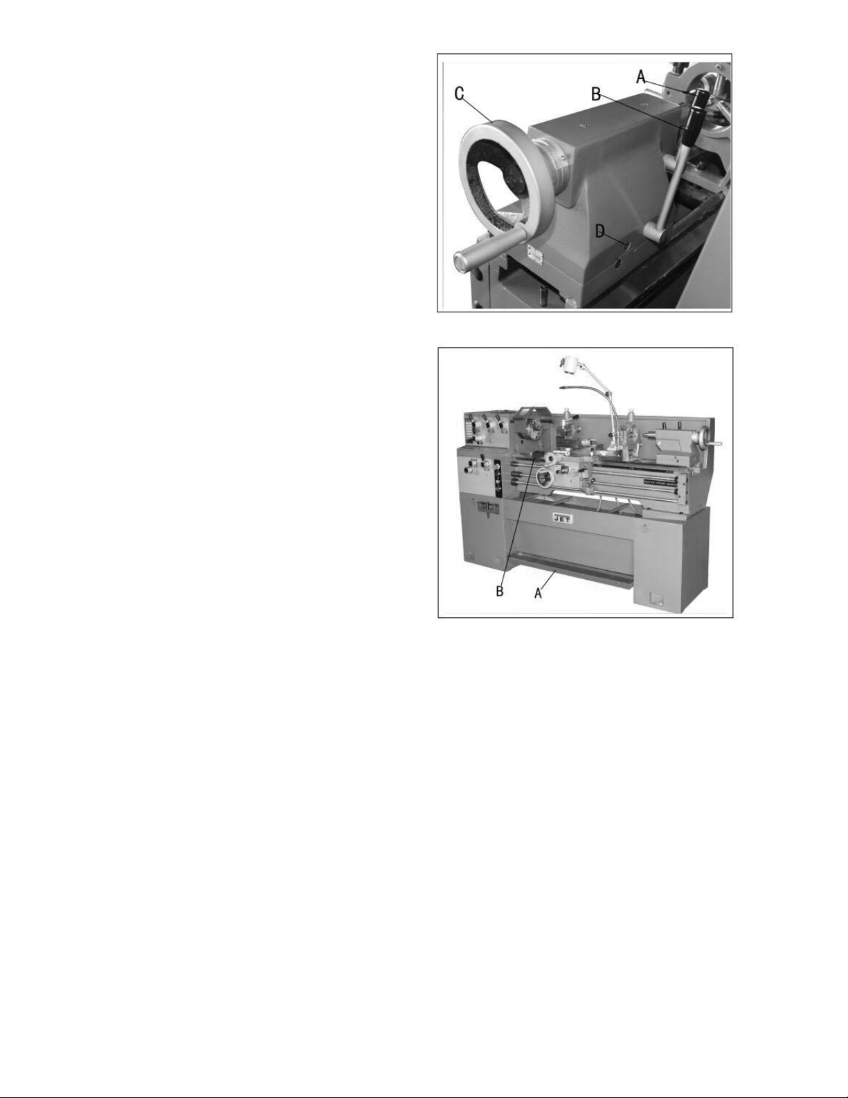
Tailstock
The tailstock (A, Fig. 13) slides on a v-way and can
be locked at any location by a clamping lever. The
tailstock has a heavy duty spindle with a Morse
Taper #3.
Figure 12
Leadscrew and feed Rrod
The leadscrew (B, Fig. 13) and feed rod (C, Fig.
13) are mounted on the front of the machine bed.
They are connected to the gearbox at the left for
automatic feed and lead, and are supported by
bushings on both ends. Both are equipped with
brass shear pins.
Figure 13
11
Gear box
The gear box (D, Fig. 13) is made from high quality
cast iron and is mounted to the left side of the
machine bed.
Steady rest
The steady rest (E, Fig. 13) serves as a support for
shafts on the free tailstock end. The steady rest is
mounted on the bedway and secured from below
with a bolt, nut and locking plate. The sliding
fingers require continuous lubrication at the contact
points with the workpiece to prevent premature
wear.
To set the steady rest:
1. Loosen three hex socket screws.
2. Loosen knurled screw and open sliding fingers
until the steady rest can be moved with its
fingers around the workpiece. Secure the
steady rest in position.
3. Set the fingers snugly to the workpiece and
secure by tightening three hex socket cap
screws. Fingers should be snug b ut not overly
tight. Lubricate sliding points with Mobil D TE®
Oil Heavy Medium.
4. After prolonged use, the fingers will show
wear. Re-mill or file the tips of the fingers.
Follow rest
The traveling follow rest (F, Fig. 13) is mounted on
the saddle and follows the movement of the turning
tool. Only two fingers are required as the place of
the third is taken by the turning tool. The follow rest
is used for tuning operations on long, slender
workpieces. It prevents flexing of the workpiece
from the pressure of the cutting tool.
The sliding fingers are set similar to the steady
rest, free of play, but not binding. Always lubricate
with Mobil DTE® Oil Heavy Me dium.
Figure 13 (repeated)
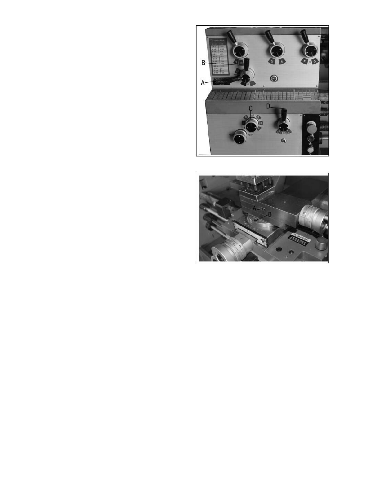
Controls
1. Control Panel - located on front of gearbox.
A. Coolant On-Off Switch (A, Fig. 14) –
tu rns coolant pump on and off.
B. Power Indicator Light (B, Fig. 14) – lit
whenever lathe has power.
C. Emergency Stop Switch (C, Fig. 14) –
depress to stop all machine functions.
Caution: Lathe will still have power.
Twist to re-set.
D. Jog Switch (D, Fig. 14) – Press and
release to advance spindle momentarily.
Figure 14
12
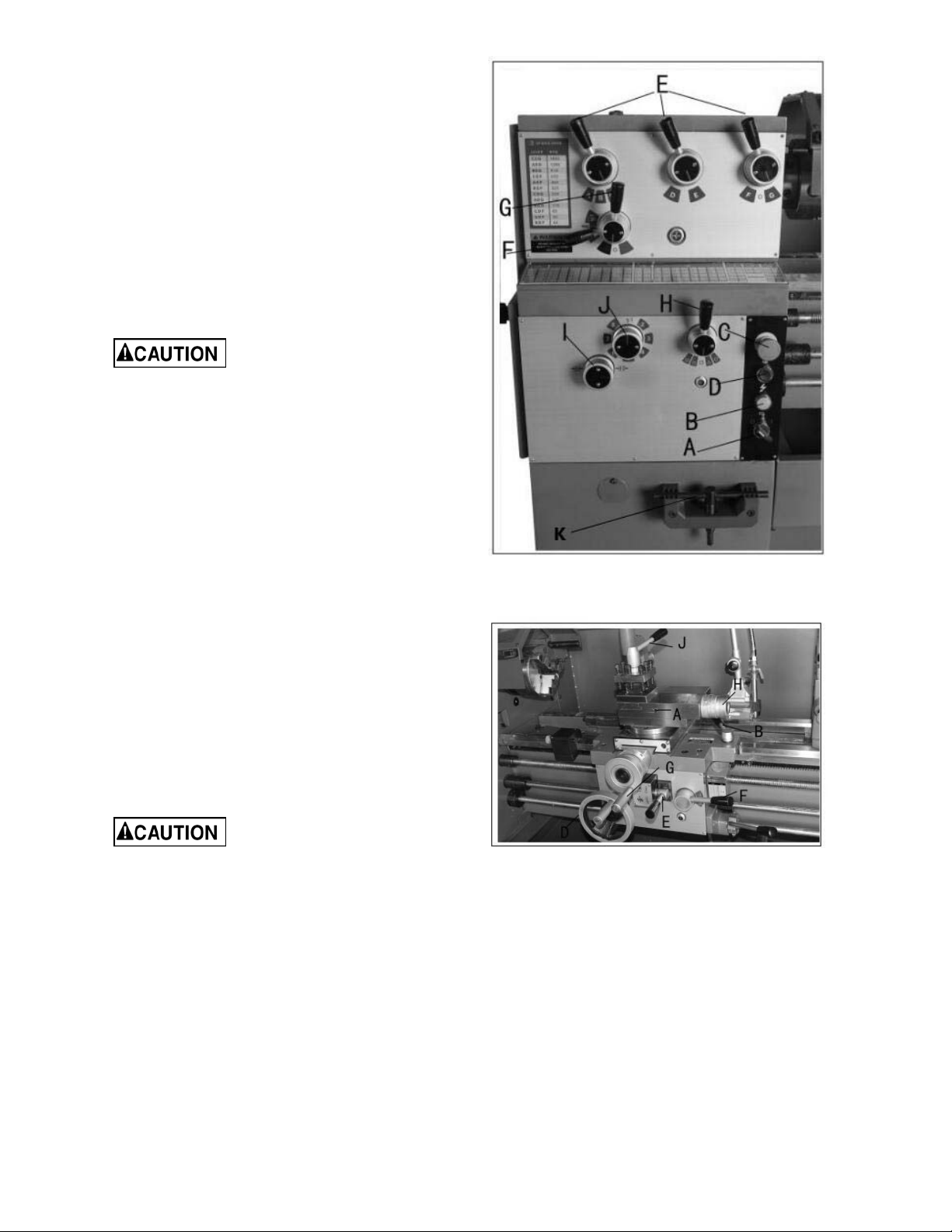
2. Headstock Gear Change Levers (E, Fig. 14)
– located on front of the headstock. Move
levers according to speed chart for desired
setting.
3. Leadscrew/Feed Rod Directional Lever (F,
Fig. 14) – located on front of headstock.
Moving the lever up causes carriage travel
toward the tailstock. Moving the lever down
causes carriage travel toward the headstock.
When chuck is spinning in the forward or
counter-clockwise direction. Do not move
lever while machine is running.
4. Feed/Lead Selector Lever (G, Fig. 14) –
located on the front of the headstock. Used
whenever setting up for threading or feeding.
In the "A" posit ion, never run
the lathe higher than 650 RPM.
5. Feed/Lead Selector Lever (H, Fig. 14) –
located on the front of the gearbox. Used in
setting up for feeding and threading.
Positions "F" and "D" are for the feed rod.
Positions "E" and "C" are f or the feed screw.
Position "0" is neutral.
6. Lock Knob (I, Fig. 14) – located on the front
of the gearbox. With the knob in the six
o'clock position, feed/lead selector knob (J,
Fig. 14) may be adjusted. With the knob in
the twelve o'clock position, the feed/lead
selector knob (J, Fig. 14) is locked.
7. Feed/Lead Selector Knob (J, Fig. 14) –
located on front of the gearbox. Used for
setting up for feeding and threading.
Figure 14 (repeated)
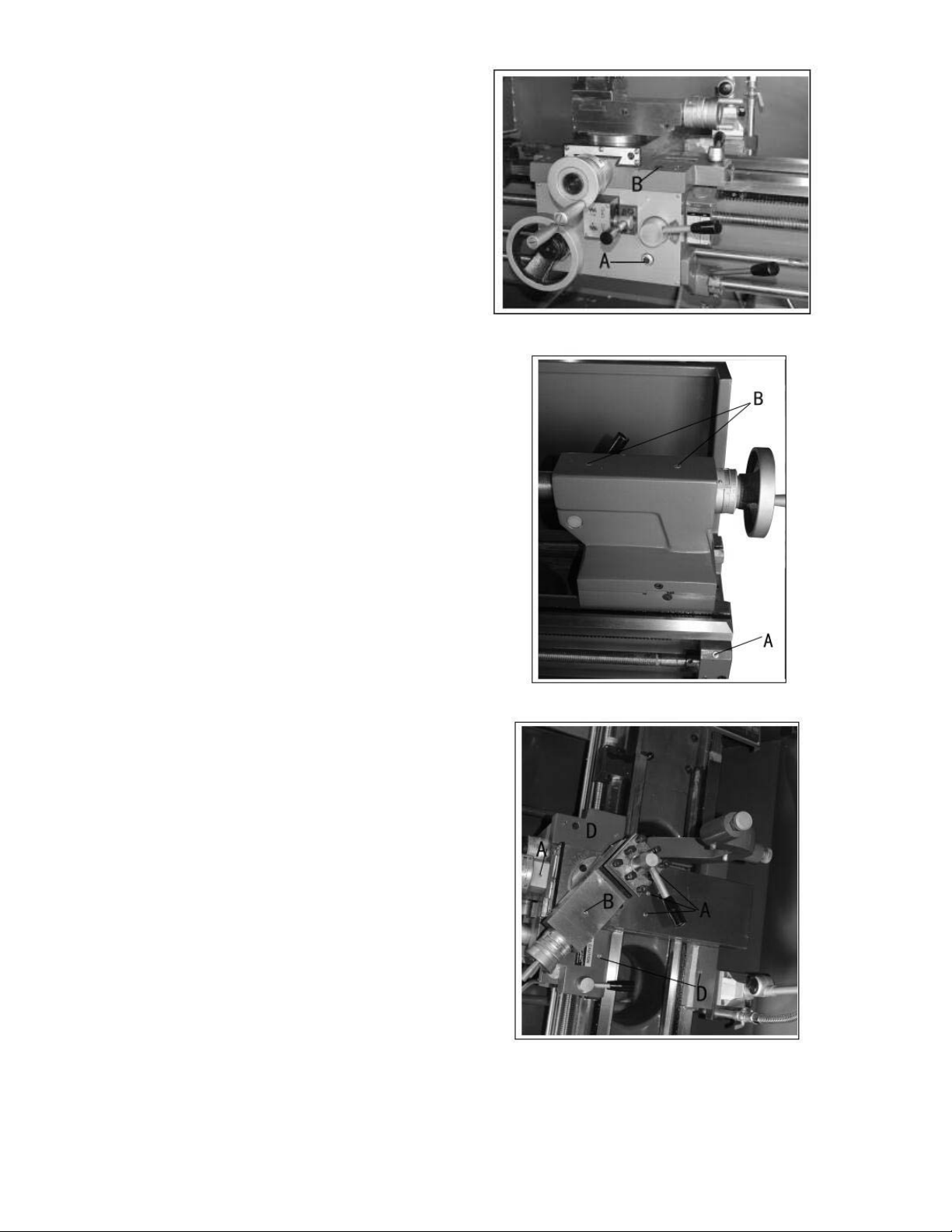
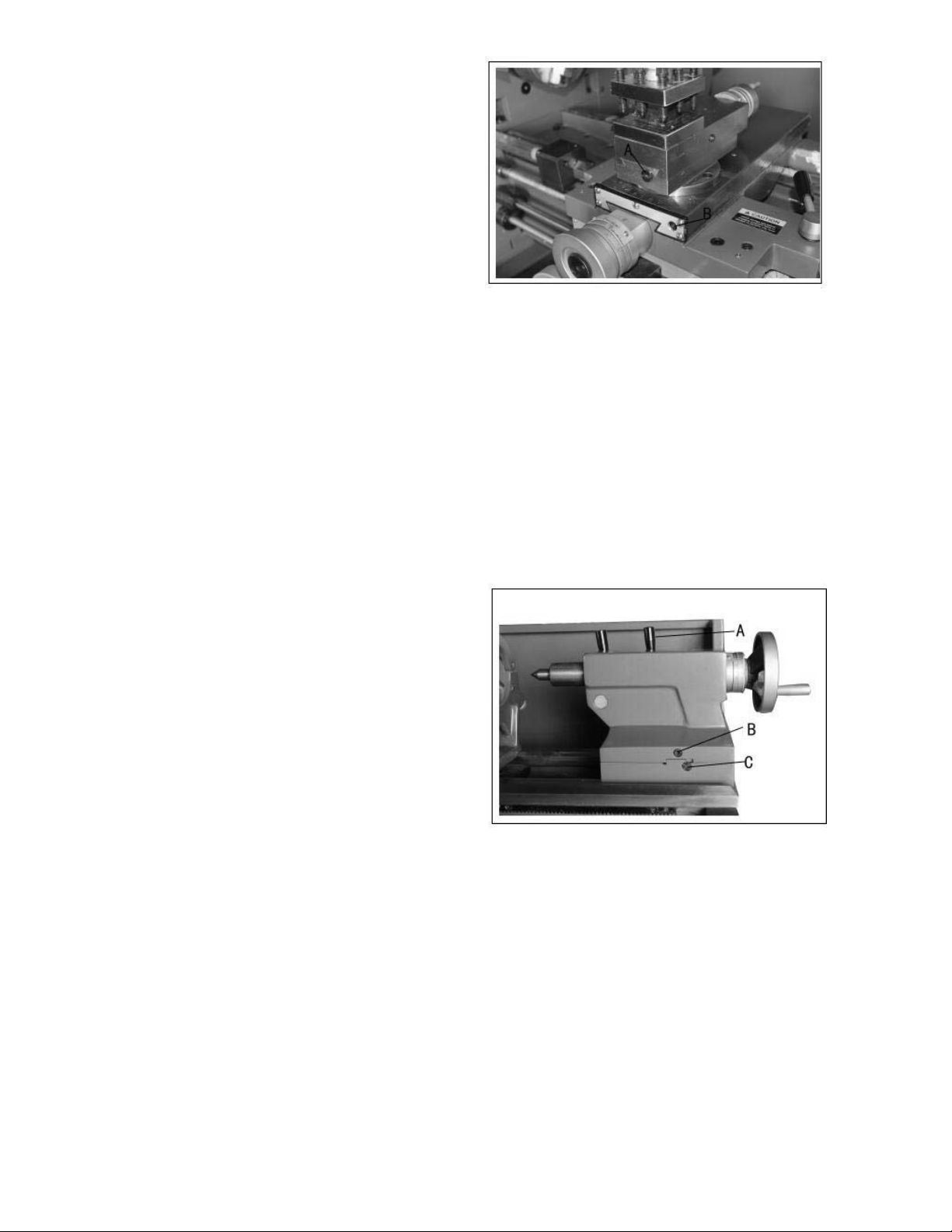
8. Compound Lock (A, Fig. 15) – hex socket
screw located on left side of com pound. Turn
clockwise to lock and counter-clockwise to
unlock.
9. Carriage Lock (B, Fig. 15) – lock handle
located on top of carriage. Turn clockwise to
lock. Turn counter-clockwise to unlo ck.
Carriage lock must be
unlocked before engaging automatic
feeds or damage to lathe may occur.
10. Longitudinal Traverse Hand Wheel - (D,
Fig. 15) – located on the apron assembly.
Rotate hand wheel clockwise to move the
apron assembly toward the tailstock. Rotate
the wheel counter-clockwise to move the
apron assembly toward the headstock.
11. Feed Selector (E, Fig. 15) – located in the
center front of the apron assembly. Pushing
lever to the left and down activates the
crossfeed function. Pulling lever to the right
and up activates the longitudinal function.
Figure 15
13
12. Half Nut E ngage Lever (t hread cutting) (F,
Fig. 15) – located on front of the apron. Move
the lever down to engage. Move the lever up
to disengage.
13. Cross Traverse Handwheel (G, Fig. 15) –
located above the apron assembly. Rotate
clockwise or counter-clockwise to move, or
position.
14. Compound Rest Traverse Handwheel (H,
Fig. 15) – located on the end of the
compound slide. Rotate clockwise or counterclockwise to move, or position.
15. Tool Post Clamping Lever (J, Fig. 15) –
located on top of the tool post. Rotate
counter-clockwise to loosen and clockwise to
tighten.
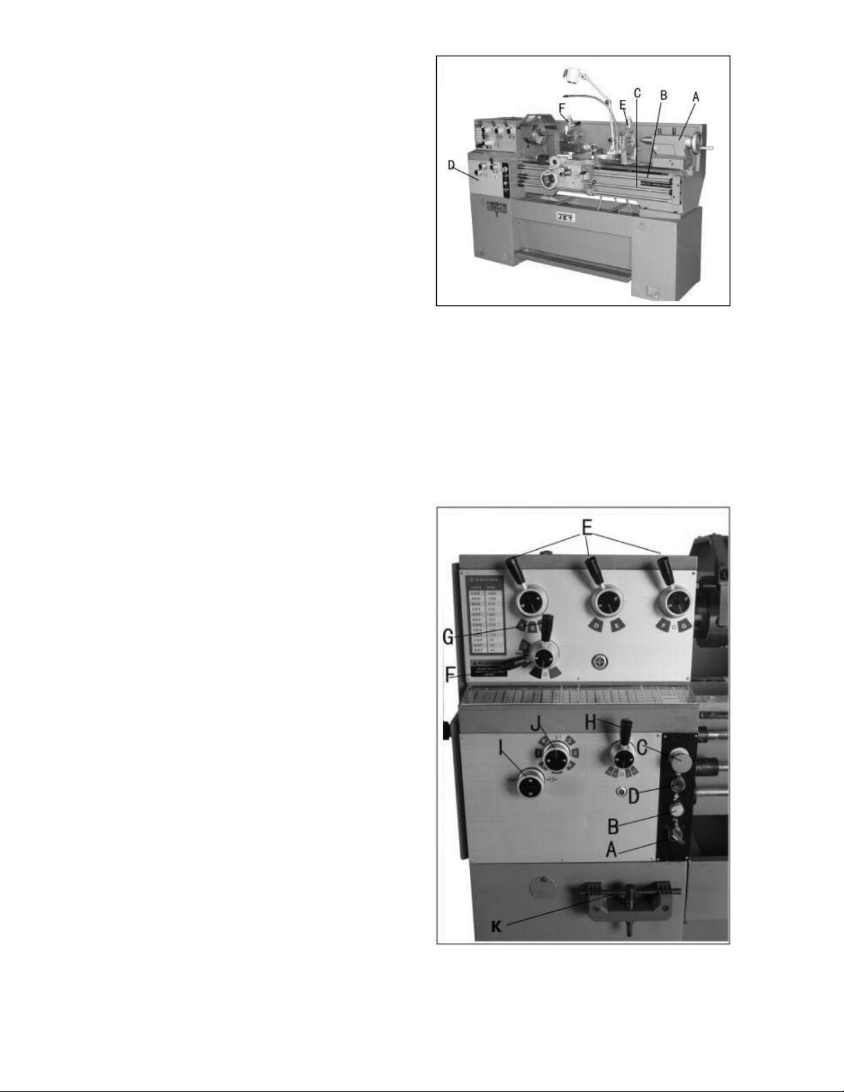
16. Tailstock Quill Clamping Lever (A, Fig. 16)
– located on the tailstock. Lift up to lock the
spindle. Push down to unlock.
17. Tailstock Clamping Lever (B, Fig. 16) –
located on the tailstock. Lift up lever to lock.
Push down lever to unlock.
18. Tailstock Quill Traverse Handwheel (C,
Fig. 16) – located on the tailstock. Rotate
clockwise to advance the quill. Rotate
counter-clockwise to retract the quill.
19. Tailstock Off-Set Adjustment (D, Fig. 16) –
Two hex socket cap screws located on the
tailstock base are used to off-set the tailstock
for cutting tapers. Loosening one screw while
tightening the other off sets the tailstock.
20. Foot Brake (A, Fig. 17) – located between
stand pedestals. Depress to stop all lathe
functions.
21. Micro Carriage Stop (B, Fig. 17) – located
on the lathe bed. Loosen two hex socket cap
screws underneath body and slide along bed
to desired position. Tighten screws to hold in
place.
22. Main Power Switch (not shown) – located on
the electrical box door on the rear of the
lathe. Turns main power to the lathe on and
off.
11.0 Operation
Figure 16
Figure 17
11.1 Break-in procedure
During manufacture and testing, this lathe has
been operated in the low R.P.M. range for three
hours.
To allow time for the gears and bearings to breakin and run smoothly, do not run the lathe above
650 R.P.M. for the first six hours of operation and
use.
14
11.2 Feed and thread selection
1. Reference the feed and thread found on the
gear box faceplate tables (A, Fig. 18 a nd page
24 of this manual).
2. Move levers (B, C, D, E & F, Fig. 18) to the
appropriate positions according to the chart.
11.3 Change gears replacement
The 25T, 127T, 50T gears are installed in the end
gear compartment when delivered from the factory.
This combination will cover most inch feeds and
threads under normal circumstances.
The 30T, 32T, and two 40T gears found in the tool
box are used with different combinations as
indicated on feed and thread tables (A, Fig. 18).
1. Disconnect the machine from the power
source (unplug).
2. Open the door on the left end of the
headstock.
3. Loosen nuts (A & B, Fig. 19).
4. Move quadrant (C, Fig. 19) out of the way and
hold in place temporarily by tightening nut (A &
B, Fig. 19).
Figure 18
5. Remove hex socket cap screws (D and/or E,
Fig. 19), depending on which gear is to be
changed.
6. Install new gear(s) and tighten in place with a
hex socket cap screw.
7. Loosen nut (B, Fig. 19), move quadrant back
so teeth mesh on gears, and tighten nuts (A &
B, Fig. 19).
8. Caution: Make sure there is a backlash of
.002”-.003” between gears. Setting the gears
too tight will cause excessive noise and wear.
9. Close the door and connect the machine to the
power source.
11.4 Automatic feed operation and
feed changes
1. Move the forward/reverse selector (A, Fig. 20)
up or down depending on desired direction.
2. Set selector levers (A, B, C, & D, Fig. 21) to
desired rate.
Note: for feeding, lever (D) will be set at "F"
or "D", depending on desired feed rate.
Figure 19
Figure 20
15
11.5 Powered carriage travel
1. Push lever (B, Fig. 20) to the left and down to
engage crossfeed.
2. Pull lever to the right and up to engage
longitudinal feed.
11.6 Thread cutting
1. Set forward/reverse lever (A, Fig. 20) up or
down depending on the desired direction.
2. Set selector levers (A, B, C , and D, Fig. 21) to
desired rate.
Note: For threading, lever (D) will be set at
"C" or "E", depending on desired thread.
3. Push lever (B, Fig. 19) to the right.
4. Engage the half nut lever (C, Fig. 20).
5. To cut inch threads, reference the feed and
thread tables. The half nut lever and the
threading dial are used to thread in the
conventional manner. The thread dial chart
specifies at which point a thread can be
entered using the threading dial.
6. To cut metric threads, the half nuts must be
left continually engaged once the start point
has been selected and the half nut is initially
engaged (thread dial cannot be used).
11.7 Compound rest
The compound rest is located on top of the cross
slide and can be rotated 360 degrees. Loose n the
two socket head cap screws (A, Fig. 22) on the
compound rest base. There is a calibrated dial (in
degrees B, Fig. 22) below the rest to assist in
placement of the compound to the desired angle.
12.0 Adjustments
After a period of time, wear i n some of the moving
components may need to be adjusted:
12.1 Saddle
1. Locate f our hex nuts found on t he bottom rear
of the cross slide and back off one full turn
each.
2. Turn each of the four set screws with a hex
wrench until a slight resistance is felt. Do not
over tighten these screws.
Figure 21
Figure 22
3. Move the carriage with the hand wheel and
determine if the drag is to your preference.
Readjust the set screws as necessary to
achieve the desired drag.
4. Hold the socket set screw firmly with a hex
wrench and tighten the hex nut to lock the set
screw in place.
16
5. Move the carriage again and readjust if
necessary.
Note: Over adjustment will cause excessive
premature wear of the gibs.
12.2 Cross slide
If the cross slide is too loose, follow procedure
below to tighten:
1. Loosen the rear gib screw (not shown)
approximately one turn.
2. Tighten the front gib screw (B, Fig. 23) a
quarter turn. Turn the cross slide handwheel to
see if the cross slide is still loose. If it is still
loose, tighten the front screw a bit more and
try again.
3. When the cross slide is properly adjusted,
tighten the rear gib screw.
Note: Over adjustment will cause excessiv e
and prematur e wear of the gibs.
Figure 23
12.3 Compound rest
Follow the same procedure as the cross slide
adjustment to adjust the compound rest. Rear gib
screw is shown (A, Fig. 23). Front gib screw (not
shown) is by the handwheel.
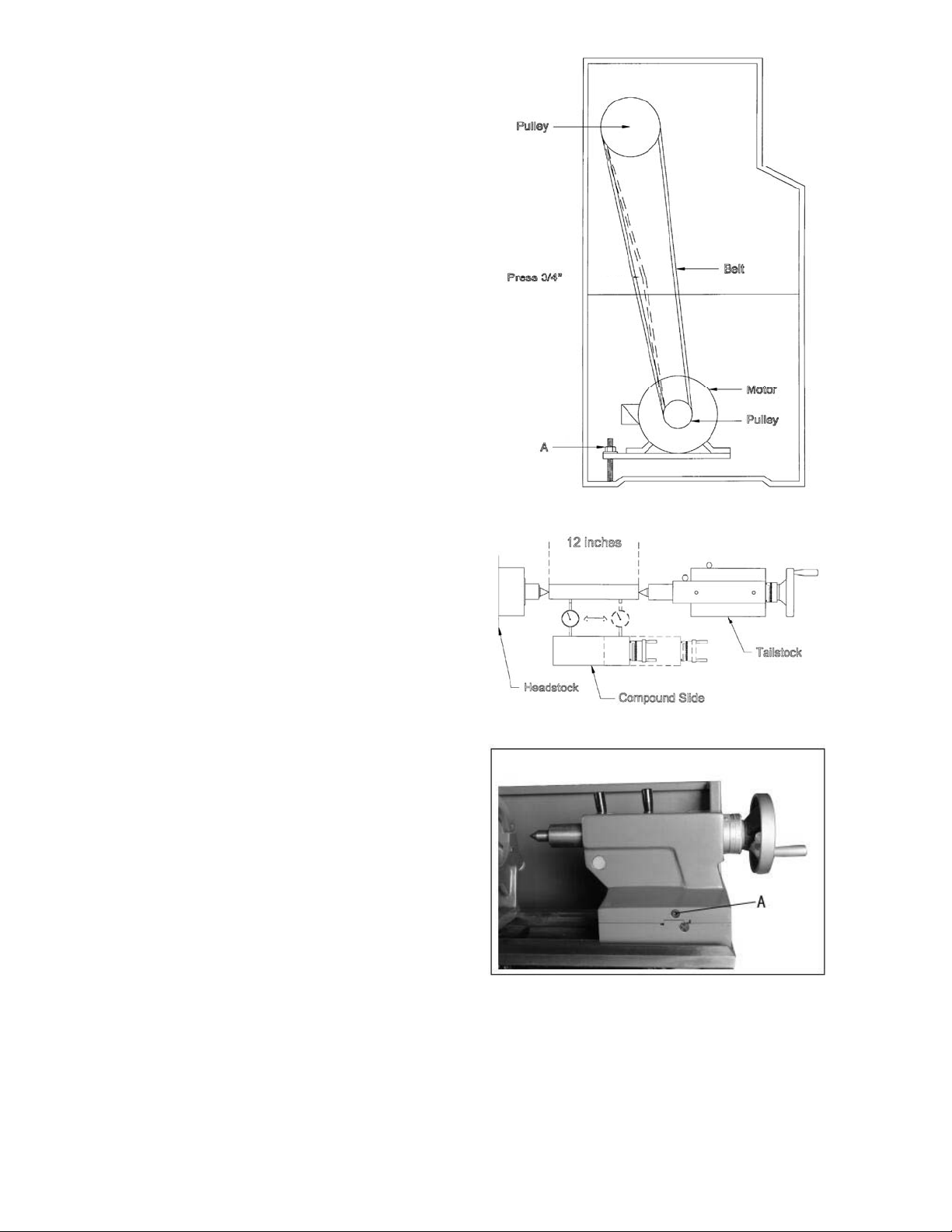
12.4 Tailstock
If the handle (A, Fig. 24) will not lock the tailstock,
follow the procedure below :
1. Lower the handle to the unlocked position.
2. Slide the tailstock to an area that allows
access to the underside of the tailstock.
3. Tighten tailstock clamping bolt (underside of
tailstock) 1/4 turn. Test for proper locking.
Repeat as necessary.
12.5 Tailstock off-set
Follow the procedure below to off-set the tailstock
to cut shallow tapers:
1. Lock tailstock in position by raising locking
handle (A, Fig. 24).
2. Alternately loosen and tighten two hex socket
cap screws (B, Fig. 24).
Figure 24
12.6 Tailstock gibs
Take up play in the tailstock by tightening two gib
screws (C, Fig. 24) on either side of the tailstock
base.
Note: Do not over tig hten. Excessive tightening will
lead to premature wear of the gibs and mating
parts
17

12.7 Headstock alignment
The headstock has been aligned at the factory and
should not require adjustment. However, if
adjustment is deemed necessary, follow the
procedure below to align the headstock:
1. Using a machinist's precision level on the
bedways, make sure the lathe is level side to
side and front to back. If the lathe is not level,
correct to a level condition before proceeding.
Re-test alignment if any leveling adjustments
were made.
2. From steel bar stock of approximately two
inches in diameter, cut a piece approximately
eight inches long.
3. Place two inches of bar stock into chuck a nd
tighten chuck. Do not use the tailstock or
center to support the other end.
4. Set up and cut along five inches of bar stock.
5. Using a micrometer, measure the bar stock
next to the chuck and at the end. The
measurement should be the same.
6. If the measurements are not the same and
adjustment is required, loosen hex socket cap
screws (A, Fig. 25) whic h holds the headstock
to the bed. Do not loosen completely; some
drag should remain.
7. Adjust two screw nuts (B, Fig. 25) located on
the endgear side of the headstock. Loosen
one and tighten the other. Make another cut.
Keep adjusting screw nuts after each cut until
the bar stock measurements are the same.
Tighten all headstock screws.
Figure 25
12.8 Removing gap section
1. To remove gap section, locate two nuts (A,
Fig. 26) in the center of the gap section.
2. Using an open end wrench, tighten the two
nuts. This will cause the taper pins to release.
Remove the taper pins.
3. Remove six hex socket cap screws (B, Fig.
26) with a hex key wrench.
4. Gap section can now be removed.
12.9 Installing gap section
1. Clean the bottom and the ends of the gap
se ction thoroughly.
2. Set gap section in place and align.
3. Remove nuts from the taper pins.
4. Slide taper pins in their respective ho les and
seat using a mallet. Install nuts on the taper
pins finger tight.
5. Install six socket head cap screws and tighten
securely.
Figure 26
18
12.10 Belt replacement and
adjustment
1. Disconnect machine from the power
source (unplug).
2. Open the end gear cover and lower cover on
the headstock side.
3. Take tension off old belts by loosening motor
mount hex nut (A, Fig. 27).
4. Remove belts. Install new belts onto pulleys.
5. Tension by tightening motor mount hex nut
until 8 lbs. force causes approximately 3/4"
deflection on belts.
6. Close end gear door, install cover and connect
lathe to the power source.
12.11 Aligning tailstock to headstock
Before proceeding, headstock should be aligned.
See section labeled "Headstock Alignment".
1. Fit a 12" ground steel bar between center s of
the headstock and tailstock (Fig. 28).
2. Fit a dial indicator to the compound slide and
traverse the center line of the bar, using the
carriage movement.
Figure 27
3. If tailstock adjustment is needed, alternately
loosen and tighten front and rear hex socket
cap screws (A, Fig. 29).
Figure 28
Figure 29
19

13.0 Operation tables
13.1 Metric thread table
13.2 Inch lead and feed table
20
 Loading...