

Page 1
Operating Instructions and Parts Manual
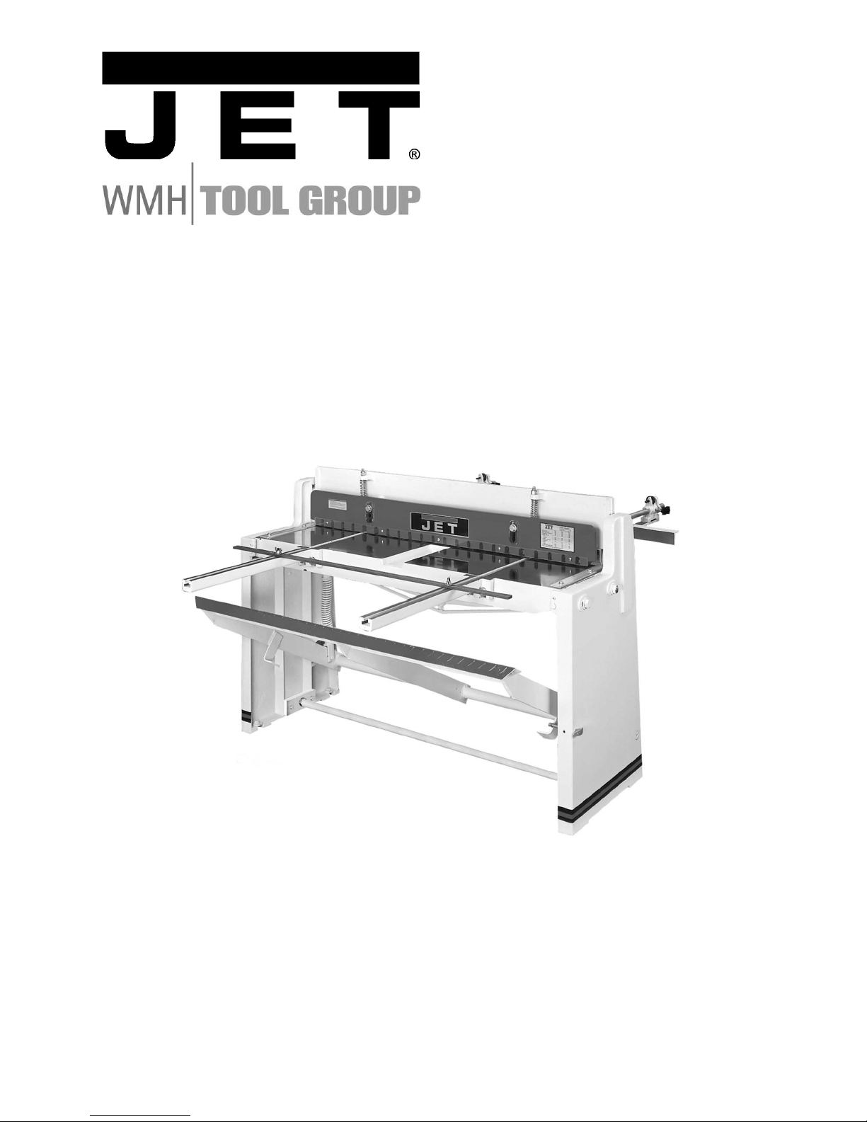
Foot Shear
Models FS-1636N, FS-1652N
WMH TOOL GROUP
2420 Vantage Drive
Elgin, Illinois 60123 Part No. M-754636
Ph.: 800-274-6848 Revision G 12/05
www.wmhtoolgroup.com Copyright © WMH Tool Group
Page 2

2
Warranty and Service
WMH Tool Gr oup warrants ever y product it sell s. If one of our tools needs s ervice or repai r, one of our
Authorized Service Centers located throughout the United States can provide quick service or
information.
In most cases, a W MH Tool Group Servi ce Center can assist i n authori zing repai r work, obtai ning part s,
or perform routine or major maintenance repair on your JET product.
For the name of an Aut horized Service Cent er in your area, pl ease call 1-800-274-6848, or vi sit our web
site at www.wmhtoolgroup.com
More Information
Remember, WMH Tool Group i s consistently adding new products to the li ne. For complete, up-to-dat e
product information, check with your local WMH Tool Group distributor, or visit our web site at
www.wmhtoolgroup.com
WMH Tool Group Warranty
WMH Tool Group makes every effort to assure that its product s meet high quality and durabi lity standards
and warrants to the original retail consumer/purchaser of our products that each product be free from
defects in mat erials and workmanship as foll ows: 1 Y EAR LIMITED WARRANTY ON ALL PRODUCTS
UNLESS SPECIFIED OTHERWISE. This Warranty does not apply to defects due directly or i ndirectly to
misuse, abuse, negl igence or acc idents, norm al wear-and-tear , repair or alterati ons outside our f aciliti es,
or to a lack of maintenanc e.
WMH TOOL GROUP LIMITS ALL IMPLIED WARRANTIES TO THE PERIOD SPECIFIED ABOVE,
BEGINNING FROM THE DATE THE PRODUCT WAS PURCHASED AT RETAIL. EXCEPT AS STATED
HEREIN, ANY IMPLIED WARRANTIES OR MERCHANTABILITY AND FITNESS ARE EXCLUDED.
SOME STATES DO NOT ALLOW LIMITATIONS ON HOW LONG THE IMPLIED WARRANTY LASTS,
SO THE ABOVE LIMITATION MAY NOT APPLY TO YOU. IN NO EVENT SHALL WMH TOOL GROUP
BE LIABLE FOR DEATH, INJURIES TO PERSONS OR PROPERTY, OR FOR INCIDENTAL,
CONTINGENT, SPECIAL, OR CONSEQUENTIAL DAMAGES ARISING FROM THE USE OF OUR
PRODUCTS. SOME STATES DO NOT ALLOW THE EXCLUSION OR LIMITATION OF INCIDENTAL
OR CONSEQUENTIAL DAMAGES, SO THE ABOVE LIMITATION OR EXCLUSION MAY NOT APPLY
TO YOU.
To take advantage of this warranty, the product or part must be returned for examination, postage
prepaid, to an Authorized Service Center designated by our office. Proof of purchase date and an
explanati on of the complaint m ust accompany the merchandi se. If our inspecti on discloses a defec t, we
will either repair or replace the product at our discr eti on, or ref und the purc hase price if we cannot r eadil y
and quickly provide a repai r or replac ement. We will return the repai red product or replacem ent at WMH
Tool Group’s ex pense, but if it is determ ined there i s no defect, or that the def ect resulted f rom causes
not within the scope of WMH Tool Group’s warranty, then the user must bear the cost of storing and
returning t he product . This warranty gives you specifi c legal right s; you may al so have ot her right s, which
vary from state t o state.
WMH Tool Group sells through distri butors only. Members of the WMH Tool Group reserve the right to
effect at any time, wit hout prior notice, alter ations to parts, fittings and accessory equi pment, which they
may deem necessary for any reason whatsoever.
Page 3

3
WARNING
For your own safety, read the owner’s manual before operating the foot shear.
This foot shear is designed and intended for use by properly trained and experienced personnel
only. If you are not familiar wit h the p rop er and safe operation of a foot shear, do not use until
proper training and know ledge has been obtained.
1. KEEP GUARDS IN PLACE and in working order.
2. KEEP ALL BODY PARTS AWAY FROM MOVING PARTS. Avoid placing any part of your body
near belts, cutt er s, gear s, etc.
3. DO NOT EXCEED 16 GAUGE RATED CAPACITY on this shear.
4. KEEP THE WORK AREA CLEAN. Cluttered areas and work benches invite accidents.
5. KEEP CHILDREN AWAY. All visitors should be kept a saf e distanc e from the work area.
6. MAKE THE WORKSHOP KID PROOF with padlocks, m aster swit c hes, or by r em ov ing st ar ter keys.
7. DON’T FORCE THE MACHINE. It will do the job bett er and saf er at t he rate for which it was
designed.
8. USE THE RIGHT MACHINE. Don’t force a machine or att ac hm ent t o do a job for whi c h it was not
designed.
9. WEAR PROPER APPAREL. Do not wear loose clothing, glov es, nec k ties, rings, bracelets, or other
jewelry which may get caught in moving parts. Non-slip footwear i s recom m ended. Wear protective
hair covering to contain long hair.
10. ALWAYS USE SAFETY GLASSES. Also use face or dust masks if the cutting operation is dusty.
Everyday eyeglasses only have impact resistant l enses; they are not safety glasses.
11. DON’T OVERREACH. Keep proper footing and balance at all times.
12. MAINTAIN TOOLS WITH CARE. Keep tools sharp an d c lean for the best and safest performance.
Follow instructions for lubricating and changing accessories.
13. NEVER STAND ON A MACHINE. Serious injury could oc c ur if t he machine tipped.
14. CHE CK DAM AGED P ARTS. Before further use of the machine, a guard or other part that is
damaged should be carefully checked to determine that it will oper ate properly and perform its
intended function - check for alignment of moving parts, binding of moving parts, breakage of parts,
mounting, and any other conditions that may affect it s operati on. A guard or other part that is
damaged should be properly repaired or replaced.
15. SHEET METAL STOCK HAS SHARP EDGES. To prevent cuts, use caution when handling.
16. KEEP HANDS AND FINGERS clear of the ar ea in fr ont and rear of the shearing blades.
17. DO NOT USE THE MACHINE for any purpose other than for which it was designed
18. FAILURE TO COMP LY with all of these warning s may cause serious injury.
19. S OME DUST CREATED BY power sanding, sawing, grinding, drilling and other constr uc tion
activities contains chemicals known to cause cancer, birth defects or other reproductiv e harm. Some
examples of these chemicals are:
• Lead from lead based paint
• crystalline silica from bricks and cement and other masonry products
• arsenic and chromium from chemically-treat ed lum ber .
Your risk from these exposures varies, depending on how often you do this type of work. To reduce
your exposure to these chemicals: work in a well ventilated area, and work wit h appr oved safety
equipment, such as those dust masks that are specifically desi gned to filter out microscopic particles
20. DO NOT OPERA TE TOOL while under the influence of drugs, alcohol or any m edic ation.
Page 4

4
Specifications: FS-1636N FS-1652N
Stock Number.................................................................754636...................................................754652
Capacity (mild steel)....................................................... 16 gauge............................................. 16 gauge
Shearing Length Capacity...............................................36” ................................................................52”
Back Gauge Capacity .....................................................25.5”..........................................................25.5”
Front Gauge Capacity.....................................................28”................................................................28”
Overall Dimensions (LxWxH)..........................................46 ½” x 21 ¼” x 41 ½”......62 ½” x 21 ¼” x 41 ½”
Net Weigh t (lb s.).............................................................824 ............................................................1014
Uncrating and Clean-Up
1. Remove the crate from around the m ac hine.
2. Carefully clean all rust protected surfaces
with a mild solvent or kerosene and a soft
rag. Do not use lacquer thinner, paint
thinner, or gasoline. These will damage
painted surf aces.
3. Coat all machi ned surfaces with a li ght coat
of oil to inhibit rust.
4. Remove the bolts holding the machine to the
skid.
5. Carefully move the machine to a level
foundation. Machine location must allow
access to all sides.
Assembly Note: Prior to shipment the foot
shear is adjusted at the factory for proper
operation. If the machine does not operate
properly or the stand does not sit squarely on
the floor, proceed to setup.
Stop Assembly
The (#) in the text ref er s to the break down.
1. Attach the two front arm extensions #6 to
the bed with four hex cap screws and
washers.
2. Attach the stop #71 to the front extension
arms with T-nuts #72.
3. Attach the rear stop #59 to the adjusting
block assembl y #61.
4. Insert the rod #58 through the adjusting
block assembly and into the cutter bar.
Tighten in plac e with knobs #65.
Setup
1. Loosen four bolts #21. Loosen adjusting
screws #18 & 19. The bed must rest
squarely on the right and left hand side
panels at all four corners while screws are
loose. Shim legs at floor if necessary.
Tighten hardware.
2. Use set screw #18 and hex cap scr ew #19,
to adjust the lower blade towards or away
from the upper bl ade. The di stance bet ween
the upper and lower blades should be 0.002-
0.005”. Do not let the blades overlap.
3. Place a heavy sheet of paper (~0.005”) in
the cutting position, along the entire length
of the bed, and slowly press the foot lever.
4. If the shear doe s n ot cut the paper move the
lower blade towards the upper blade.
5. If the shear cut s the paper on the ends, but
not the center, turn the tie-rod adjusting
screw #37, clockwise until the paper is cut
the entire length.
6. If the shear cut s the paper in the c enter, but
not the ends, turn t he tie-rod adjusting screw
#37, counter-c lockwise unti l the paper is cut
the entire length.
7. Make sure t he scales #15 a nd #16 on top of
the bed are square to the blade, and also
show the correct distance from the blade.
8. Make test cuts to verify the scales are
correct.
Blade Care
The 2-way upper blade can be removed and
flipped 180°, for a sharp edge bef ore having to
sharpen the blade.
Wipe the blade li ghtly with oil. Lubr icate all piv ot
points on the machine daily.
Spring Tension
The spring return can be adjusted on the foot
lever by tightening #46 hex nuts.
The spring return can be adjusted on the hold
down #3 by tightening #10 hex nuts.
Gib Adjustment
There are three hex c ap screws #32 that can be
adjusted for play in the shim #31. Adjust for
smooth trav el.
Page 5

5
Breakdown for FS-1636N & FS-1652N Foot Shear
Page 6

6
Parts List for the FS-1636N & FS-1652N Foot Shear
Index Part
No. No. Description Size Quantity
1..........FS1636N-1................... Table..................................................... ...............................................1
............ FS1652N-1................... Table..................................................... ...............................................1
2..........FS1636N-2................... Cutter Bar.............................................. ...............................................1
............ FS1652N-2................... Cutter Bar.............................................. ...............................................1
3..........FS1636N-3................... Hold Down............................................. ...............................................1
............ FS1652N-3................... Hold Down ............................................. ...............................................1
4..........FS1636N-4................... R.H. Side Panel..................................... ...............................................1
5..........FS1636N-5................... L.H. Side Panel...................................... ...............................................1
6..........FS1636N-6................... Front Arm Extension.............................. ...............................................2
7..........FS1636N-7................... Screw....................................................M12x45...................................4
8..........FS1636N-8................... Spring.................................................... ...............................................2
9..........FS1636N-9................... Stud....................................................... ...............................................2
10........ FS1636N-10.................Nut........................................................M12.........................................2
11........ FS1636N-11.................Screw....................................................M12x80...................................2
12........ FS1636N-12.................Washer.................................................. ...............................................2
13........ FS1636N-13.................Finger Guard ......................................... ...............................................1
............ FS1652N-13................. Finger Guard ......................................... ...............................................1
14........ FS1636N-14.................Screw....................................................M6x12.....................................4
15........ FS1636N-15.................Table Scale (L.H.).................................. ...............................................1
16........ FS1636N-16.................Table Scale (R.H.)................................. ...............................................1
17........ FS1636N-17.................Screw....................................................M8x20.....................................4
18........ FS1636N-18.................Set Screw..............................................M10x45...................................2
19........ FS1636N-19.................Screw....................................................M10x50...................................2
21........ FS1636N-21.................Bolt........................................................M16x115.................................4
22........ FS1636N-22.................Washer..................................................M16.........................................4
23........ FS1636N-23.................Nut........................................................M16.........................................4
24........ FS1636N-24.................Upper Knife ........................................... ...............................................1
............ FS1652N-24................. Upper Knife ........................................... ...............................................1
25........ FS1636N-25.................Lower Knife ........................................... ...............................................1
............ FS1652N-25................. Lower Knife ........................................... ...............................................1
26........ FS1636N-26.................Screw....................................................M10x40...................................7
27........ FS1636N-27.................Screw....................................................M10x45...................................6
28........ FS1636N-28.................Washer.................................................. ...............................................7
29........ FS1636N-29.................Washer.................................................. ...............................................6
30........ FS1636N-30.................Spring Cap ............................................ ...............................................4
31........ FS1636N-31.................Gib........................................................ ...............................................2
32........ FS1636N-32.................Screw....................................................M10x55...................................6
33........ FS1636N-33.................Nut........................................................M10.........................................6
34........ FS1636N-34.................Rod ....................................................... ...............................................1
............ FS1652N-34................. Rod ....................................................... ...............................................1
35........ FS1636N-35.................Washer..................................................M16.........................................2
36........ FS1636N-36.................Nut........................................................M16.........................................2
37........ FS1636N-37.................Screw....................................................M16x80...................................1
38........ FS1636N-38.................Nut........................................................M16.........................................1
39........ FS1636N-39.................Washer..................................................M16.........................................1
40........ FS1636N-40.................Hex Socke t Cap S cre w..........................M10x30...................................2
41........ FS1636N-41.................Spring.................................................... ...............................................2
42........ FS1636N-42.................Swivel Top............................................. ...............................................2
43........ FS1636N-43.................Swivel Bottom........................................ ...............................................2
44........ FS1636N-44.................Stud....................................................... ...............................................2
46........ FS1636N-46.................Nut........................................................M16.........................................2
47........ FS1636N-47.................Scale (metric)........................................ ...............................................2
48........ FS1636N-48.................Scale (inches)........................................ ...............................................2
49........ FS1636N-49.................Screw....................................................M4x8.......................................4
50........ FS1636N-50.................Pin.........................................................Ø12x70...................................2
51........ FS1636N-51.................Pin.........................................................Ø12x45...................................2
Page 7

7
53........ FS1636N-53.................Brake Pin............................................... ...............................................2
58........ FS1636N-58.................Rod ....................................................... ...............................................2
59........ FS1636N-59.................Stop....................................................... ...............................................1
............ FS1652N-59................. Stop....................................................... ...............................................1
60........ FS1636N-60.................Extension Bar........................................ ...............................................2
61........ FS1636N-61.................Adjusting Block...................................... ...............................................2
62........ FS1636N-62.................Adjusting Dial......................................... ...............................................2
63........ FS1636N-63.................Adjusting Screw..................................... ...............................................2
64........ FS1636N-64.................Nut........................................................M10.........................................2
65........ FS1636N-65.................Knob...................................................... ...............................................4
67........ FS1636N-67.................Adjusting Bracket ................................... ...............................................2
68........ FS1636N-68.................Screw....................................................M10x25...................................4
69........ FS1636N-69.................Bolt........................................................M10x25...................................2
70........ FS1636N-70.................Nut........................................................M10.........................................2
71........ FS1636N-71.................Stop....................................................... ...............................................1
............ FS1652N-71................. Stop....................................................... ...............................................1
72........ FS1636N-72.................“T” Nut................................................... ...............................................3
74........ FS1636N-74.................Wing Nut................................................ M10.........................................3
75........ FS1636N-75.................Bevel Gauge.......................................... ...............................................1
76........ FS1636N-76.................Washer.................................................. ...............................................4
77........ FS1636N-77.................Washer..................................................M10.........................................5
78........ FS1636N-78.................Washer.................................................. ...............................................2
79........ FS1636N-79.................Set Screw..............................................M10x50...................................2
80........ FS1636N-80.................Plate...................................................... ...............................................2
81........ FS1636N-81.................Screw....................................................M12x35...................................4
82........ FS1636N-82.................Nut........................................................M16.........................................4
83........ FS1636N-83.................Connection Bar......................................Ø16x1081mm .........................1
............ FS1652N-83................. Connection Bar......................................Ø16x1463mm .........................1
902......FS1636N-902............... Pedal A ssembly..................................... ...............................................1
............ FS1652N-902............... Pedal Assembly ..................................... ...............................................1
............ FS1636N-ID................. ID Label (not shown).............................. ...............................................1
............ FS1652N-ID................. ID Label (not shown).............................. ...............................................1
............ FS1636N-W ................. W arning Label (not shown).................... ...............................................1
............ FS1636N-J................... JET Label (not shown)........................... ...............................................1
Page 8

8
WMH Tool Gr ou p
2420 Vantage Drive
Elgin, Illinois 60123
Phone: 800-274-6848
www.wmhtoolgroup.com
 Loading...