

Page 1

Operating Instructions and Parts Manual
16-Gauge Foot-Operated Corner Notcher
Model FN-16
JET
427 New Sanford Road
LaVergne, Tennessee 37086 Part No. M-755017
Ph.: 800-274-6848 Edition 3 08/2018
www.jettools.com Copyright © 2017 JET
1
Page 2

1.0 IMPORTANT SAFETY
INSTRUCTIONS
WARNING – To reduce risk of injury:
1. Read and understand the entire owner’s
manual before attempting assembly or
operation.
2. Read and understand the warnings posted on
the machine and in this manual. Failure to
comply with all of these warnings may cause
serious injury.
3. Replace warning labels if they become
obscured or removed.
4. This sheet metal notcher is designed and
intended for use by properly trained and
experienced personnel only. If you are not
familiar with the proper and safe operation of a
sheet metal notcher, do not use it until proper
training and knowledge have been obtained.
5. Do not use this notcher for purposes other than
its intended use. If used for other purposes, JET
disclaims any real or implied warranty and holds
itself harmless from any injury that may result
from that use.
6. Always wear ANSI Z87.1 approved safety
glasses or face shield while using this machine.
(Everyday eyeglasses only have impact
resistant lenses; they are not safety glasses.)
7. Wear ear protectors (plugs or muffs) if noise
exceeds safe levels.
8. Wear appropriate footwear, s uch as steel-toed
shoes, when working with metal materials.
9. Before operating the machine, remove tie,
rings, watches, other jewelry, and roll sleeves
up past the elbows. Do not wear loose clothing.
Confine long hair.
10. Keep the floor around the machine clean and
free of scrap material, oil and grease.
11. Keep machine guards in place at all times when
the machine is in use. If removed for
maintenance purposes, use extreme caution
and replace the guards immediately upon
completion of maintenance.
12. Check damaged parts. Before further use of the
machine, a guard or other part that is damaged
should be carefully checked to determine that it
will operate properly and perform its intended
function. Check for alignment of moving parts,
binding of moving parts, breakage of parts,
mounting and any other conditions that may
affect its operation. A guard or other part that is
damaged should be properly repaired or
replaced.
13. Use the right tool. Do not force a tool or
attachment to do a job for which it was not
designed.
14. Remove adjusting keys and wrenches. Form a
habit of checking to see that keys and adjusting
wrenches are removed from the machine
before operating.
15. Give your work undivided attention. Looking
around, carrying on a conversation and "horseplay" are careless acts that can result in serious
injury.
16. Keep visitors a safe distance from the work
area. Keep children away.
17. Make your workshop child proof with padlocks,
master switches or by removing starter keys.
18. Do not overreach. Failure to maintain proper
working position can cause you to fall into the
machine or allow clothing to get caught, pulling
you into the machine.
19. Keep the floor around the machine clean and
free of scrap material, oil and grease.
20. Use recommended accessories; improper
accessories may be hazardous.
21. Do not operate this machine while under the
influence of drugs, alcohol or any medication.
22. Keep blades sharp and clean for safe and best
performance.
23. Deburr any sharp metal edges of the workpiece
before placing it into the machine. Use leather
gloves when handling workpieces.
24. Keep hands away from blade area during
operation.
25. Provide for adequate space surrounding work
area and non-glare, overhead lighting.
26. Anchor machine to the floor to prevent tipping.
27. Do not stand on the machine. Serious injury
could occur if the machine tips over.
28. Do not attempt to cut material thicker than the
listed capacity of the notcher.
29. Do not cut round or bar stock on this machine,
as it may damage the knives.
30. Use only JET factory authorized replacement
parts and accessories; otherwise, the warranty
and guarantee are null and void.
2
Page 3

WARNING: This product can expose you to
chemicals including lead which is known to the
State of California to cause cancer and birth
defects or other reproductive harm. For more
information go to http://www.p65warnings.ca.
gov.
Familiarize yourself with the following safety
notices used in this manual:
This means that if precautions are
not heeded, it may result in minor injury and/or
possible machine damage.
This means that if precautions are
not heeded, it may result in serious, or possibly even
fatal, injury.
SAVE THESE INSTRUCTIONS
WARNING: Some dust, fumes and gases
created by power sanding, sawing, grinding,
drilling, welding and other construction activities
contain chemicals known to the State of
California to cause cancer and birth defects or
other reproductive harm. Some examples of
these chemicals are:
• lead from lead based paint
• crystalline silica from bricks, cement and other
masonry products
• arsenic and chromium from chemically treated
lumber
Your risk of exposure varies, depending on how
often you do this type of work. To reduce your
exposure to these chemicals, work in a wellventilated area and work with approved safety
equipment, such as dust masks that are
specifically designed to filter out microscopic
particles. For more information go to
http://www.p65warnings.ca.gov/ and http://
www.p65warnings.ca.gov/wood.
3
Page 4

2.0 Table of contents
Section Page
1.0 IMPORTANT SAFETY INSTRUCTIONS ....................................................................................................... 2
2.0 Table of contents ............................................................................................................................................ 4
3.0 About this manual .......................................................................................................................................... 4
4.0 Specifications ................................................................................................................................................. 5
4.1 Base hole spacings .................................................................................................................................... 5
5.0 Setup .............................................................................................................................................................. 6
5.1 Shipping contents ....................................................................................................................................... 6
5.2 Unpacking and locating .............................................................................................................................. 6
6.0 Adjustments ................................................................................................................................................... 6
6.1 Table position ............................................................................................................................................. 6
6.2 Stroke depth ............................................................................................................................................... 7
6.3 Ram tightness ............................................................................................................................................ 7
6.4 Setting blade gap ....................................................................................................................................... 7
6.5 Handle adjustment ..................................................................................................................................... 7
7.0 Operation ....................................................................................................................................................... 7
8.0 User-maintenance .......................................................................................................................................... 7
8.1 Lubrication .................................................................................................................................................. 7
8.2 Additional servicing .................................................................................................................................... 8
9.0 Troubleshooting FN-16 Corner Notcher ......................................................................................................... 8
10.0 Replacement Parts ....................................................................................................................................... 8
10.1.1 FN-16 Corner Notcher – Exploded View ............................................................................................... 9
10.1.2 FN-16 Corner Notcher – Parts List ...................................................................................................... 10
11.0 Warranty and service ................................................................................................................................. 11
3.0 About this manual
This manual is provided by JET, covering the safe operation and maintenance procedures for a JET Model FN16 Corner Notcher. This manual contains instructions on installation, safety precautions, general operating
procedures, maintenance instructions and parts breakdown. Your machine has been designed and constructed
to provide consistent, long-term operation if used in accordance with the instructions set forth in this document.
If there are questions or comments, please contact your local supplier or JET. JET c an also be reached at our
web site: www.jettools.com.
Retain this manual for future reference. If the machine transfers ownership, the manual should accompany it.
Read and understand the entire contents of this manual before attempting assembly or
operation! Failure to comply may cause serious injury!
Register your product online – http://www.jettools.com/us/en/service-and-support/warranty/registration/
4
Page 5

4.0 Specifications
Model number
Stock number 755017
Capacities
Maximum cutting thickness, mild steel 16 gauge – 1.5 mm (1/16 in.)
Notching angle 90-degree fixed
Maximum notching capacity 80 x 80 mm (3.15 x 3.15 in.)
Stroke length 25 mm (1 in.)
Blade length 80 mm (3 in.)
Main materials
Cutting head Steel
Blades Hardened steel, HRC 50-55
Table Steel, ground surface
Stand and foot pedal Steel
Dimensions
Table size LxW 260 x 260 mm (10-1/4 x 10-1/4 in.)
Table height from floor 965 mm (38 in.)
T-slot size WxD 3/8 x 5/8 in. (9.5 x 16 mm)
Overall dimensions LxWxH 427 x 300 x 1170 mm (16-3/4 x 11-3/4 x 46 in.)
Shipping dimensions LxWxH 1270 x 400 x 560 mm (50 x 15-3/4 x 33 in.)
Weights
Net weight 81 kg (178 lbs)
Shipping weight 105 kg (231 lbs)
FN-16
Table 1
L = length, W = width, H = height, D = depth
The specifications in this manual were current at time of publication, but because of our policy of continuous
improvement, JET reserves the right to change specifications at any time and without prior notice, without incurring
obligations.
4.1 Base hole spacings
Figure 4-1
5
Page 6

Read and understand the entire
contents of this manual before attempting setup
or operation. Failure to comply may cause
serious injury.
5.0 Setup
The FN-16 Notcher is shipped fully assembled. The
user will be required only to secure it to floor and
ensure it is properly adjusted and lubricated before
operating.
5.1 Shipping contents
1 Notcher
3 Hex wrenches, 6,8,10 mm
1 Open-end wrench, 13/16 mm
1 Operating instructions and parts manual
1 Product registration card
5.2 Unpacking and locating
1. Inspect contents for shipping damage. Report
any damage immediately to your distributor and
shipping agent. Do not discard any shipping
material until machine is assembled and
operating properly.
2. Position notcher in a well-lighted area, with
enough room on all sides for general
maintenance and handling of materials. Anchor
machine to a stable floor, preferably concrete,
using lag screws or other appropriate fasteners
through holes in base. Before tightening to floor,
level the machine; use shims if needed.
3. Exposed metal surfaces have been given a
protective coating. Remove this with a soft cloth
and a cleaner-degreaser or kerosene. Do not
use gasoline, paint thinner, or acetone, as these
may damage painted surfaces. Do not use an
abrasive pad, as it may scratch polished
surfaces.
4. Insert SAE 20W oil into hole atop cutting head
(see Figure 6-1).
5. Apply a light coat of oil, such as SAE 30, to table
surface to inhibit rust.
Figure 6-1 (shown with guards removed; all guards
must be installed before operating)
2. Remove three (3) hex cap bolts with washers
(B, Figure 6-2) from beneath table; two at front
and one at back.
3. Remove two (2) socket head screws (C, Figure
6-2). Remove table.
4. Rotate table and install at opposite side of
cutting head.
5. Insert bolts/washers (B, Figure 6-2) and
screws/washers (C, Figure 6-2). Hand tighten
only at this time.
6. Verify appropriate blade gap (see sect. 6.4.)
and make adjustments if needed.
7. After setting blade gap, tighten bolts and screws
(B/C) securely.
6.0 Adjustments
6.1 Table position
See Figures 6-1 and 6-2 (shown with table mounted
on right side of cutting head).
The table, with lower blades attached, can be
positioned on left or right side of cutting head for
user convenience. The upper blade assembly must
also be rotated.
1. Remove blade guard (A, Figure 6-1).
Figure 6-2
6
Page 7

8. Remove four screws securing upper blade to
ram (#24, sect. 10.1.1). Rotate upper blade to
match new table position. Insert screws and
tighten upper blade securely in new position.
9. Reinstall blade guard (A, Figure 6-1).
6.2 Stroke depth
Stroke depth has been set by the manufacturer so
that foot pedal at its lowest point will cause upper
blade edge to descend below lower blade edge.
Should future adjustment be needed, loosen hex nut
and turn stop bolt (D, Figure 6-1) as needed.
Retighten hex nut against block to secure setting.
6.3 Ram tightness
Normal wear on the ram may cause need for future
adjustment. Loosen any of the eight nuts (E) and
turn screws (F, Figure 6-1) at front and side as
needed to modify drag on ram block. The ram
should slide smoothly up and down with just enough
drag to prevent shifting or free falling.
6.4 Setting blade gap
5. Slightly loosen screws (C, Figure 6-2).
6. Loosen nuts on four adjustment screws (G,
Figure 6-2) and turn adjustment screws as
needed to adjust gap between lower and upper
blades on both sides of table. Feeler gauge
should be snug but still able to be smoothly
removed.
7. NOTE: If a feeler gauge is not available, make
incremental adjustments according to step #6,
then tighten the screws (C), and make test cuts.
Continue to adjust as needed until notcher is
cutting properly.
8. Tighten nuts on the adjustment screws (G,
Figure 6-2) to secure setting.
9. Tighten center screws (C, Figure 6-2).
10. Reinstall blade guard (A, Figure 6-2).
6.5 Handle adjustment
To adjust T-stop handles (H, Figure 6-1) to more
convenient position: pull up on handle and rotate,
then release, making sure handle settles back onto
pin.
The notcher blades are designed for “splay” cutting,
in which the cut begins at outside edge of material.
The blades are pre-set by the manufacturer for
notching 16-gauge material, with 0.004 in. (0.10mm)
blade gap.
If misalignment has occurred, or table has been
moved to other side of head, the gap should be
inspected and readjusted as needed.
1. Remove blade guard (A, Figure 6-1).
2. Verify that lower blades are secured to table
and they are flush at front corner, forming a 90degree angle.
3. Press f oot pedal to engage blades, and keep
pedal in lowered position.
4. As a general rule, blade gap should be
approximately 6% of stock thickness. For
precise measurement, slide a feeler gauge (not
provided) between upper and lower blades.
Blade gap should be approx. 0.002 to 0.004inches (0.05 to 0.10mm). See Figure 6-3.
Figure 6-3: gap set for 16ga. material
7.0 Operation
1. Position T-blocks for desired notch size, using
attached scales for general reference. Tighten
handles.
2. Position workpiece against T-blocks and step
on foot pedal to make cut. The cut-off piece will
fall through to the floor.
Protective footwear should
be worn during operation.
3. Release foot pedal.
8.0 User-maintenance
8.1 Lubrication
Use caution when working
around blade area to prevent injury to fingers.
Keep blade area free of deposits or shavings, which
can impede cut quality and hasten blade wear.
Keep table and T-slots clean. Periodically apply light
coat of SAE 30 oil or equivalent to exposed metal
surfaces, such as table, blades and T-slots, to inhibit
rust.
Periodically insert SAE 20W oil through hole in top
cover to lubricate ram mechanism.
Periodically apply oil to foot pedal pivot points.
7
Page 8

Maintain sharp blades. If they become dull, resharpen or replace. NOTE: The two lower blades
are double-edged; if one edge becomes dull,
remove blade from table and flip it end-for-end for a
fresh edge. See Figure 6-3 for identification of the
cutting edges.
8.2 Additional servicing
Any additional servicing should be performed by
authorized service personnel.
9.0 Troubleshooting FN-16 Corner Notcher
Symptom Possible Cause Correction
Machine cuts with
difficulty
Edges of cut are rough
or rolled.
Poor cut quality.
Machine capacity exceeded. Use materials within rated capacity.
Improper lubrication. Follow lubricating guidelines.
Dull blade(s) Sharpen or replace.
Blade gap incorrect. Adjust blade gap.
Insufficient workpiece material on each
side of blade.
Machine capacity exceeded. Use materials within rated capacity.
Blades dry; improper lubrication. Follow lubricating guidelines.
Blades dull or damaged. Resharpen or replace blades.
Blades are loose. Check all blades for tightness.
Make sure there is sufficient length of
material before and behind blade.
10.0 Replacement Parts
Replacement parts are listed on the following pages. To order parts or reach our service department, call 1-800274-6848 Monday through Friday, 8:00 a.m. to 5:00 p.m. CST. Having the Model Number and Serial Number of
your machine available when you call will allow us to serve you quickly and accurately.
Non-proprietary parts, such as fasteners, can be found at local hardware stores, or may be ordered from JET.
Some parts are shown for reference only, and may not be available individually.
8
Page 9
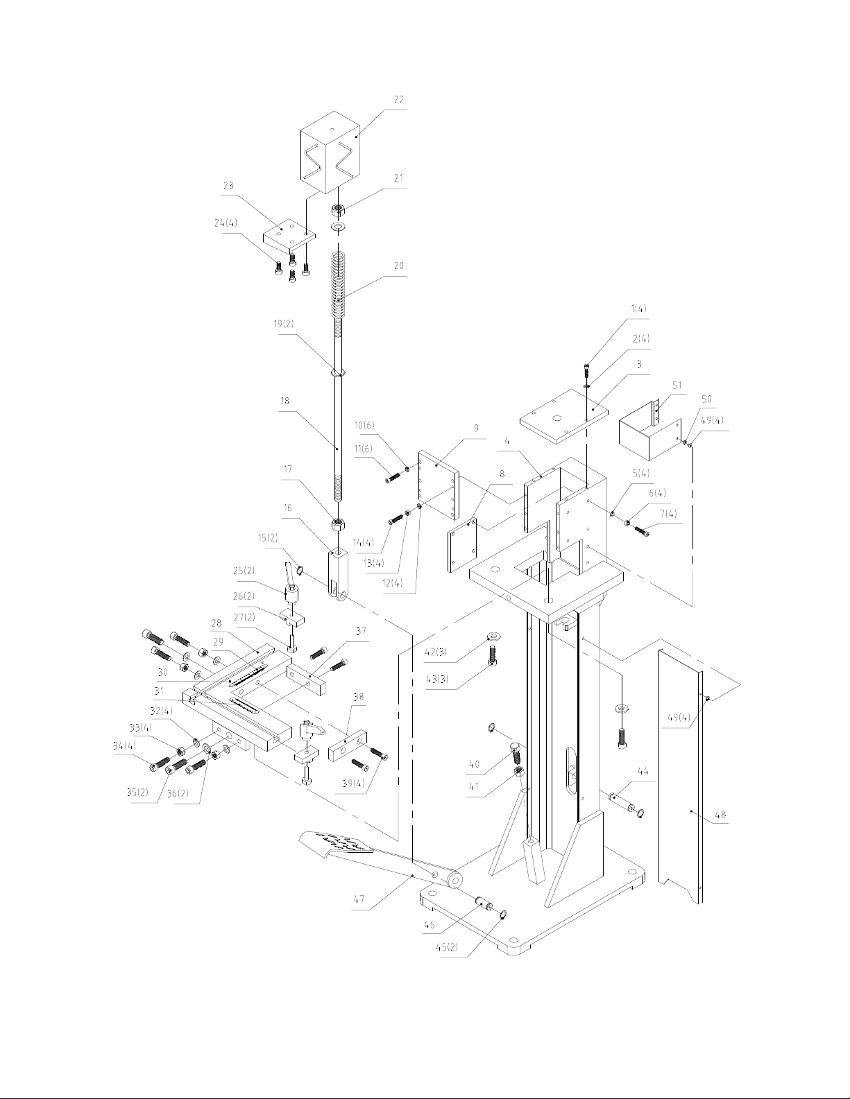
10.1.1 FN-16 Corner Notcher – Exploded View
9
Page 10

10.1.2 FN-16 Corner Notcher – Parts List
Index No Part No Description Size Qty
1 ................ TS-1503051 .............. Socket HD Cap Screw ............................................. M6-1.0x20 ..................... 4
2 ................ TS-1550041 .............. Flat Washer ............................................................. M 6 ................................. 4
3 ................ FN16-3 ...................... Top Plate ................................................................. ...................................... 1
4 ................ FN16-4 ...................... Stand ....................................................................... ...................................... 1
5 ................ TS-1550041 .............. Flat Washer ............................................................. M 6 ................................. 4
6 ................ TS-1540041 .............. Hex Nut, Full ............................................................ M6-1.0 ........................... 6
7 ................ TS-1503061 .............. Socket HD Cap Screw ............................................. M6-1.0x25 ..................... 6
8 ................ FN16-8 ...................... Side Plate ................................................................ ...................................... 1
9 ................ FN16-9 ...................... Front Plate ............................................................... ...................................... 1
10 .............. TS-1540041 .............. Flat Washer ............................................................. M 6 ................................. 6
11 .............. TS-1503061 .............. Socket HD Cap Screw ............................................. M6-1.0x25 ..................... 6
12 .............. TS-1540041 .............. Flat Washer ............................................................. M 6 ................................. 4
13 .............. TS-1540041 .............. Hex Nut, Full ............................................................ M6-1.0 ........................... 4
14 .............. TS-1503071 .............. Socket HD Cap Screw ............................................. M6-1.0x30 ..................... 4
15 .............. F006044 .................... C-Retaining Ring, Ext .............................................. 16mm ............................ 2
16 .............. FN16-16 .................... Yoke......................................................................... . ..................................... 1
17 .............. TS-154009 ................ Hex Nut, Full ............................................................ M14-2.0 ......................... 1
18 .............. FN16-18 .................... Pull Rod ................................................................... .. .................................... 1
19 .............. TS-155009 ................ Flat Washer ............................................................. M 14 ............................... 2
20 .............. FN16-20 .................... Spring ...................................................................... D3.5x175mm ................ 1
21 .............. TS-154009 ................ Hex Nut, Full ............................................................ M14-2.0 ......................... 1
22 .............. FN16-22 .................... Ram ......................................................................... ...................................... 1
23 .............. FN16-23 .................... Upper Blade ............................................................. ..... ................................. 1
24 .............. TS-1504041 .............. Socket HD Cap Screw ............................................. M8-1.25x20 ................... 4
25 .............. FN16-25 .................... Adjustable Handle ................................................... M8 ................................. 2
26 .............. FN16-26 .................... T-Block..................................................................... .. .................................... 2
27 .............. FN16-27 .................... T-Bolt ....................................................................... ...................................... 2
28 .............. FN16-28 .................... Work Table .............................................................. ..... ................................. 1
29 .............. FN16-29 .................... Scale LH .................................................................. in/mm ............................ 1
30 .............. FS1652J-79 ............... Rivet......................................................................... 2x5mm .......................... 4
31 .............. FN16-31 .................... Scale RH.................................................................. in/mm ............................ 1
32 .............. TS-1550071 .............. Flat Washer ............................................................. M 10 ............................... 4
33 .............. TS-1540071 .............. Hex Nut, Full ............................................................ M10-1.5 ......................... 4
34 .............. TS-1505051 .............. Socket HD Cap Screw ............................................. M10-1.5x35 ................... 4
35 .............. TS-1506051 .............. Socket HD Cap Screw ............................................. M12-1.75x40 ................. 2
36 .............. TS-2360121 .............. Flat Washer ............................................................. M 12 ............................... 2
37 .............. FN16-37 .................... Lower Blade-2 ......................................................... 4-1/8 L ........................... 1
38 .............. FN16-38 .................... Lower Blade-1 ......................................................... 3-1/2 L ........................... 1
39 .............. TS-1504041 .............. Socket HD Cap Screw ............................................. M8-1.25x20 ................... 4
40 .............. CS315-77 .................. Hex Cap Screw ........................................................ M12-1.75x55 ................. 1
41 .............. TS-1540081 .............. Hex Nut, Full ............................................................ M12-1.75 ....................... 1
42 .............. TS-2360121 .............. Flat Washer ............................................................. M 12 ............................... 3
43 .............. TS-1506051 .............. Socket HD Cap Screw ............................................. M12-1.75x40 ................. 3
44 .............. FN16-44 .................... Long Pin .................................................................. ...................................... 1
45 .............. F006044 .................... C-Retaining Ring, Ext .............................................. 16mm ............................ 2
46 .............. FN16-46 .................... Short Pin .................................................................. ...................................... 1
47 .............. FN16-47 .................... Pedal........................................................................ ...................................... 1
48 .............. FN16-48 .................... Front Cover .............................................................. ...................................... 1
49 .............. 6286494 .................... Mach Screw, Pan Hd, Phillips ................................. M5-0.8x6 ........ ............... 8
50 .............. TS-1550031 .............. Flat Washer ............................................................. M 5 ................................. 4
51 .............. FN16-51 .................... Blade Guard ............................................................ ...................................... 1
52 .............. TS-152707 ................ Hex Wrench (not shown) ......................................... 6mm .............................. 1
53 .............. TS-227D081 .............. Hex Wrench (not shown) ......................................... 8mm .............................. 1
54 .............. 315900 ...................... Hex Wrench (not shown) ......................................... 10mm ............................ 1
55 .............. FN16-55 .................... Open-End Wrench (not shown) ............................... 13/16mm ....................... 1
56 .............. JET-92 ....................... JET Logo (not shown) ............................................. 92x38mm ...................... 1
57 .............. LM000294 ................. ID Label, FN-16 (not shown).................................... ...................................... 1
58 .............. LM000295 ................. Warning Label, FN-16 (not shown) .......................... ...................................... 1
10
Page 11

11.0 Warranty and service
JET warrants every product it sells against manufacturers’ defects. If one of our tools needs service or repair, please
contact Technical Service by calling 1-800-274-6846, 8AM to 5PM CST, Monday through Friday.
Warranty Period
The general warranty lasts for the time period specified in the literature included with your product or on the official
JET branded website.
• JET products carry a limited warranty which varies in duration based upon the product. (See chart below)
• Accessories carry a limited warranty of one year from the date of receipt.
• Consumable items are defined as expendable parts or accessories expected to become inoperable within a
reasonable amount of use and are covered by a 90 day limited warranty against manufacturer’s defects.
Who is Covered
This warranty covers only the initial purchaser of the product from the date of delivery.
What is Covered
This warranty covers any defects in workmanship or materials subject to the limitations stated below. This warranty
does not cover failures due directly or indirectly to misuse, abuse, negligence or accidents, normal wear-and-tear,
improper repair, alterations or lack of maintenance. JET woodworking machinery is designed to be used with Wood.
Use of these machines in the processing of metal, plastics, or other materials outside recommended guidelines may
void the warranty. The exceptions are acrylics and other natural items that are made specifically for wood turning.
Warranty Limitations
Woodworking products with a Five Year Warranty that are used for commercial or industrial purposes default to a
Two Year Warranty. Please contact Technical Service at 1-800-274-6846 for further clarification.
How to Get Technical Support
Please contact Technical Service by calling 1-800-274-6846. Please note that you will be asked to provide proof
of initial purchase when calling. If a product requires further inspection, the Technical Service representative will
explain and assist with any additional action needed. JET has Authorized Service Centers located throughout the
United States. For the name of an Authorized Service Center in your area call 1-800-274-6846 or use the Service
Center Locator on the JET website.
More Information
JET is constantly adding new products. For complete, up-to-date product information, check with your local distributor
or visit the JET website.
How State Law Applies
This warranty gives you specific legal rights, subject to applicable state law.
Limitations on This Warranty
JET LIMITS ALL IMPLIED WARRANTIES TO THE PERIOD OF THE LIMITED WARRANTY FOR EACH PRODUCT.
EXCEPT AS STATED HEREIN, ANY IMPLIED WARRANTIES OF MERCHANTABILITY AND FITNESS FOR A
PARTICULAR PURPOSE ARE EXCLUDED. SOME STATES DO NOT ALLOW LIMITATIONS ON HOW LONG AN
IMPLIED WARRANTY LASTS, SO THE ABOVE LIMITATION MAY NOT APPLY TO YOU.
JET SHALL IN NO EVENT BE LIABLE FOR DEATH, INJURIES TO PERSONS OR PROPERTY, OR FOR
INCIDENTAL, CONTINGENT, SPECIAL, OR CONSEQUENTIAL DAMAGES ARISING FROM THE USE OF OUR
PRODUCTS. SOME STATES DO NOT ALLOW THE EXCLUSION OR LIMITATION OF INCIDENTAL OR
CONSEQUENTIAL DAMAGES, SO THE ABOVE LIMITATION OR EXCLUSION MAY NOT APPLY TO YOU.
JET sells through distributors only. The specifications listed in JET printed materials and on official JET website are
given as general information and are not binding. JET reserves the right to effect at any time, without prior notice,
those alterations to parts, fittings, and accessory equipment which they may deem necessary for any reason
whatsoever. JET
Product Listing with Warranty Period
90 Days – Parts; Consumable items
1 Year – Motors; Machine Accessories
2 Year – Metalworking Machinery; Electric Hoists, Electric Hoist Accessories; Woodworking Machinery used
for industrial or commercial purposes
5 Year – Woodworking Machinery
Limited Lifetime – JET Parallel clamps; VOLT Series Electric Hoists; Manual Hoists; Manual Hoist
Accessories; Shop Tools; Warehouse & Dock products; Hand Tools; Air Tools
NOTE: JET is a division of JPW Industries, Inc. References in this document to JET also apply to JPW Industries,
Inc., or any of its successors in interest to the JET brand.
®
branded products are not sold in Canada by JPW Industries, Inc.
11
Page 12

427 New Sanford Road
LaVergne, Tennessee 37086
Phone: 800-274-6848
www.jettools.com
12
 Loading...