

Operating Instructions and Parts Manual
8-in x 13-in Horizontal Cut-Off Bandsaw
Models: EHB-8VS and EHB-8VSM
®
JET
427 New Sanford Road
LaVergne, Tennessee 37086
www.jettools.com
Ph.: 855-336-4032
Part No. M-891015
REV C1 9/2018
Copyright © 2017 JET

1.0 WARRANTY AND SERVICE
JET® warrants every product it sells against manufacturers’ defects. If one of our tools needs service or repair, please
contact Technical Service by calling 1-855-336-4032, 8AM to 5PM CST, Monday through Friday.
WARRANTY PERIOD
The general warranty lasts for the time period specified in the literature included with your product or on the official JET
branded website, jettools.com.
WHO IS COVERED?
This warranty covers only the initial purchaser of the product from the date of delivery.
WHAT IS COVERED?
This warranty covers any defects in workmanship or materials subject to the limitations stated below. This warranty does not
cover failures due directly or indirectly to misuse, abuse, negligence or accidents, normal wear-and-tear, improper repair,
alterations or lack of maintenance.
HOW TO GET TECHNICAL SUPPORT
Please contact Technical Service by calling 1-855-336-4032. Please note that you will be asked to provide proof of initial
purchase when calling. If a product requires further inspection, the Technical Service representative will explain and assist
with any additional action needed. JET has Authorized Service Centers located throughout the United States. For the name
of an Authorized Service Center in your area call 1-855-336-4032 or use the Service Center Locator on the JET website.
2
8-in x 13-in Horizontal Cut-Off Bandsaw

MORE INFORMATION
JET® is constantly adding new products. For complete, up-to-date product information, check with your local distributor or
visit the JET website, jettools.com.
HOW STATE LAW APPLIES
This warranty gives you specific legal rights, subject to applicable state law.
LIMITATIONS ON THIS WARRANTY
JET LIMITS ALL IMPLIED WARRANTIES TO THE PERIOD OF THE LIMITED WARRANTY FOR EACH PRODUCT.
EXCEPT AS STA TED HEREIN, ANY IMPLIED WARRANTIES OF MERCHANT ABILITY AND FITNESS FOR A P ARTICULAR
PURPOSE ARE EXCLUDED. SOME STATES DO NOT ALLOW LIMITATIONS ON HOW LONG AN IMPLIED WARRANTY
LASTS, SO THE ABOVE LIMITATION MAY NOT APPLY TO YOU.
JET SHALL IN NO EVENT BE LIABLE FOR DEATH, INJURIES TO PERSONS OR PROPERTY, OR FOR INCIDENTAL,
CONTINGENT, SPECIAL, OR CONSEQUENTIAL DAMAGES ARISING FROM THE USE OF OUR PRODUCTS. SOME
STATES DO NOT ALLOW THE EXCLUSION OR LIMITATION OF INCIDENTAL OR CONSEQUENTIAL DAMAGES, SO
THE ABOVE LIMITATION OR EXCLUSION MAY NOT APPLY TO YOU.
JET sells through distributors only . The specifications listed in JET printed materials and on of ficial JET website are given as
general information and are not binding. JET reserves the right to effect at any time, without prior notice, those alterations to
parts, fittings, and accessory equipment which they may deem necessary for any reason whatsoever. JET branded products
are not sold in Canada by JPW Industries, Inc.
NOTE: JET is a division of JPW Industries, Inc. References in this document to JET also apply to JPW Industries, Inc., or
any of its successors in interest to the JET brand.
EHB-8VS | EHB-8VSM
3

2.0 TABLE OF CONTENTS
1.0 WARRANTY AND SERVICE ...........................................................................................................................................2
2.0 TABLE OF CONTENTS ...................................................................................................................................................4
3.0 SAFETY WARNINGS ......................................................................................................................................................4
4.0 INTRODUCTION .............................................................................................................................................................6
5.0 SPECIFICATIONS ...........................................................................................................................................................6
6.0 MACHINE FEATURES ....................................................................................................................................................7
6.1 MACHINE BASE .........................................................................................................................................................7
6.2 SAW HEAD .................................................................................................................................................................7
6.3 WORK STOP ..............................................................................................................................................................8
6.4 CONTROL PANEL ......................................................................................................................................................8
6.5 AUXILIARY COOLANT HOSE ....................................................................................................................................8
7.0 UNPACKING AND ASSEMBL Y .................................................................................................... ...................................8
7.1 MACHINE SETUP .......................................................................................................................................................8
8.0 ELECTRICAL CONNECTION .........................................................................................................................................8
9.0 CONTROLS AND INDICATORS .....................................................................................................................................9
9.1 CONTROL PANEL ......................................................................................................................................................9
9.2 BLADE SPEEDS .........................................................................................................................................................9
10.0 BLADE SELECTION ...................................................................................................................................................10
10.1 BLADE BREAK-IN PROCEDURES ........................................................................................................................10
11.0 OPERATIONS .............................................................................................................................................................10
11.1 HYDRAULIC FEED CONTROL ...............................................................................................................................10
11.2 EVALUATING CUTTING EFFICIENCY ...................................................................................................................11
11.3 WORK SETUP ........................................................................................................................................................11
11.4 SETTING THE VISE FOR ANGLE CUTS (NON-MITERING VERSION ONLY) .....................................................11
11.5 SETTING THE VISE FOR SQUARE CUTS ............................................................................................................12
11.6 SETTING BED FOR MITERING CUTS (MITERING VERSION ONLY) ..................................................................12
11.7 STARTING THE SAW .............................................................................................................................................12
11.8 COOLANT FLOW AND NOZZLE POSITION ..........................................................................................................12
11.9 SETTING THE WORK STOP ..................................................................................................................................13
12.0 ADJUSTMENTS .............................................................................................................. ............................................13
12.1 BLADE TRACKING ADJUSTMENT ........................................................................................................................13
12.2 BLADE GUIDE ADJUSTMENT ...............................................................................................................................15
12.3 BLADE GUIDE BEARING ADJUSTMENT ..............................................................................................................15
12.4 DRIVE BELT TENSION ADJUSTMENT ..................................................................................................................16
12.5 VERIFYING ADJUSTMENT ACCURACY ...............................................................................................................16
12.6 SWITCH ADJUSTMENT .........................................................................................................................................17
12.7 COUNTERBALANCE SPRING TENSION ..............................................................................................................17
13.0 MAINTENANCE ..........................................................................................................................................................17
13.1 CHANGING BLADES ..............................................................................................................................................17
13.2 CHANGING THE DRIVE BELT ...............................................................................................................................18
13.3 REPLACING THE DRIVE MOTOR .........................................................................................................................19
14.0 CLEANING ..................................................................................................................................................................19
15.0 LUBRICATION .............................................................................................................................................................19
16.0 COOLANT ...................................................................................................................................................................19
17.0 TROUBLESHOOTING ................................................................................................................................................20
18.0 REPLACEMENT PARTS .............................................................................................................................................22
19.0 WIRING DIAGRAM .....................................................................................................................................................36
3.0 SAFETY WARNINGS
1. Read and understand the entire owner’s manual before attempting assembly or operation.
2. Read and understand the warnings posted on the machine and in this manual. Failure to comply with all of these warnings may cause
serious injury.
3. Replace the warning labels if they become obscured or removed.
4. This band saw is designed and intended for use by properly trained and experienced personnel only. If you are not familiar with the
proper and safe operation of a band saw, do not use until proper training and knowledge have been obtained.
5. Do not use this band saw for other than its intended use. If used for other purposes, JET
holds itself harmless from any injury that may result from that use.
6. Always wear approved safety glasses/face shields while using this band saw. Everyday eyeglasses only have impact resistant
lenses; they are not safety glasses.
7. Before operating this band saw, remove tie, rings, watches and other jewelry, and roll sleeves up past the elbows. Remove all loose
clothing and confine long hair. Non-slip footwear or anti-skid floor strips are recommended. Do not wear gloves.
4
®
, disclaims any real or implied warranty and
8-in x 13-in Horizontal Cut-Off Bandsaw

8. Wear ear protectors (plugs or muffs) during extended periods of operation.
9. Do not operate this machine while tired or under the influence of drugs, alcohol or any medication.
10. Make certain the switch is in the OFF position before connecting the machine to the power supply.
11. Make certain the machine is properly grounded.
12. Make all machine adjustments or maintenance with the machine unplugged from the power source.
13. Remove adjusting keys and wrenches. Form a habit of checking to see that keys and adjusting wrenches are removed from the
machine before turning it on.
14. Avoid contact with coolant, especially guarding your eyes.
15. Always keeps hands and fingers away from the blade when the machine is running.
16. Never hand hold the material. Always use the vise and clamp it securely.
17. Always provide adequate support for long and heavy material.
18. Keep safety guards in place at all times when the machine is in use. If removed for maintenance purposes, use extreme caution and
replace the guards immediately after maintenance is complete.
19. Check damaged parts. Before further use of the machine, a guard or other part that is damaged should be carefully checked to
determine that it will operate properly and perform its intended function. Check for alignment of moving parts, binding of moving parts,
breakage of parts, mounting and any other conditions that may affect its operation. A guard or other part that is damaged should be
properly repaired or replaced.
Do not use power tools in damp/wet locations or other dangerous environments. Do not expose them to rain. Keep work area well
20.
lighted. Provide for adequate space surrounding work area and non-glare overhead lighting.
21. Keep the floor around the machine clean and free of scrap material, oil and grease.
Keep visitors a safe distance from the work area. Keep children away. Workshop should be childproof; padlocks, master switches,
22.
remove starter keys.
23. Give your work undivided attention. Looking around, carrying on a conversation and “horse-play” are careless acts that can result in
serious injury.
24. Maintain a balanced stance at all times so that you do not fall or lean against the blade or other moving parts. Do not overreach or
use excessive force to perform any machine operation.
25. Use the right tool at the correct speed and feed rate. Do not force a tool or attachment to do a job for which it was not designed. The
right tool will do the job better and more safely.
26. Use recommended accessories; improper accessories may be hazardous.
27. Maintain tools with care. Keep blade sharp and clean for the best and safest performance. Follow instructions for lubricating and
changing accessories.
28. Maintain proper adjustment of blade tension, blade guides and thrust bearings.
29. Turn off the machine and disconnect from power before cleaning. Use a brush to remove chips or debris — do not use your hands.
30. Do not stand on the machine. Serious injury could occur if the machine tips over.
31. Never leave the machine running unattended. Turn the power off and do not leave the machine until it comes to a complete stop.
32. Be sure that the blade is not in contact with the workpiece when the motor is started. The motor shall be started and you should allow
the saw to come up to full speed before bringing the saw blade into contact with the workpiece.
33. Adjust upper guide to clear workpiece. Hold workpiece firmly against table.
34. Direction of feed — feed work into a blade or cutter against the direction of rotation of the blade or cutter only.
35. Installation work and electrical wiring must be done by qualified electrician in accordance with all applicable codes and standards.
36. Do not remove jammed pieces until blade has stopped.
WARNING: This product can expose you to chemicals including lead which is known to the State of California to cause cancer
!
and birth defects or other reproductive harm, and ethylbenzene which is known to the State of California to cause cancer. For more
information go to http://www.p65warnings.ca.gov.
WARNING: Some dust, fumes and gases created by power sanding, sawing, grinding, drilling, welding and other construction
!
activities contain chemicals known to the State of California to cause cancer and birth defects or other reproductive harm. Some
examples of these chemicals are:
• lead from lead based paint
• crystalline silica from bricks, cement and other masonry products
• arsenic and chromium from chemically treated lumber
Your risk of exposure varies, depending on how often you do this type of work. To reduce your exposure to these chemicals, work
in a well-ventilated area and work with approved safety equipment, such as dust masks that are specifically designed to filter out
microscopic particles. For more information go to http://www.p65warnings.ca.gov/ and http://www.p65warnings.ca.gov/wood.
EHB-8VS | EHB-8VSM
5
Familiarize yourself with the following safety notices used in this manual:
!
This means that if precautions are not heeded, it
may result in minor injury and/or possible machine
damage.
This means that if precautions are not heeded, it
may result in serious or even fatal injury.
!
4.0 INTRODUCTION
This manual is provided by JET® covering the safe operation and maintenance procedures for a JET Model EHB-8. This
manual contains instructions on installation, safety precautions, general operating procedures, maintenance instructions
and parts breakdown. Your machine has been designed and constructed to provide consistent, long-term operation if used
in accordance with the instructions as set forth in this document.
If there are questions or comments, please contact your local supplier or JET. JET can also be reached at our web site:
www.jettools.com. Retain this manual for future reference. If the machine transfers ownership, the manual should accompany
it.
5.0 SPECIFICATIONS
Model Number EHB-8VS EHB-8VSM
Stock Number 891015 891020
Capacity (in.):
Rectangular Stock at 90° (in.) 13(W) x 5-1/4(H), 13-1/4(W) x 2(H)
Rectangular Stock at 45° (in.) 8(W) x 8(H), 2(H) x 9-1/2(W) 8(W) x 8(H), 9-1/2(H) x 2(W)
Round Stock at 90° (in.) 8
Round Stock at 45° (in.) 8
Square Stock at 90° (in.) 8 x 8
Speeds (FPM) Variable 80~310
Motor
Blade Size (in.) 1 x 0.035 x 114.5
Blade Type Bi-metal
Blade Guides Tungsten carbide tip & ball bearing, eccentric shaft
Material Tungsten carbide inserts
Sides Eccentric shaft, ball bearings
Blade Wheel (in.) 11-5/8 diameter, cast iron
Bed Height (in.) 32 30
Dimensions (LxWxH) (in.) 62.5 x 22.4 x 48.4 (cutoff position)
Net Weight - approx. (lbs.) 660 792
Shipping Weight - approx. (lbs.) 770 924
Vise Rapid acting, screw tightening vise
Coolant Pump 1/8 Horsepower, 1Phase, 115/230V
The specifications in this manual were current at time of publication, but because of our policy of continuous improvement,
JET, reserves the right to change specifications at any time and without prior notice, without incurring obligations.
TEFC< 1-1/2 Horsepower, Capacitor Start, 1725 RPM,
1 Phase, 115/230V (prewired 115V), 18/9A
6
8-in x 13-in Horizontal Cut-Off Bandsaw
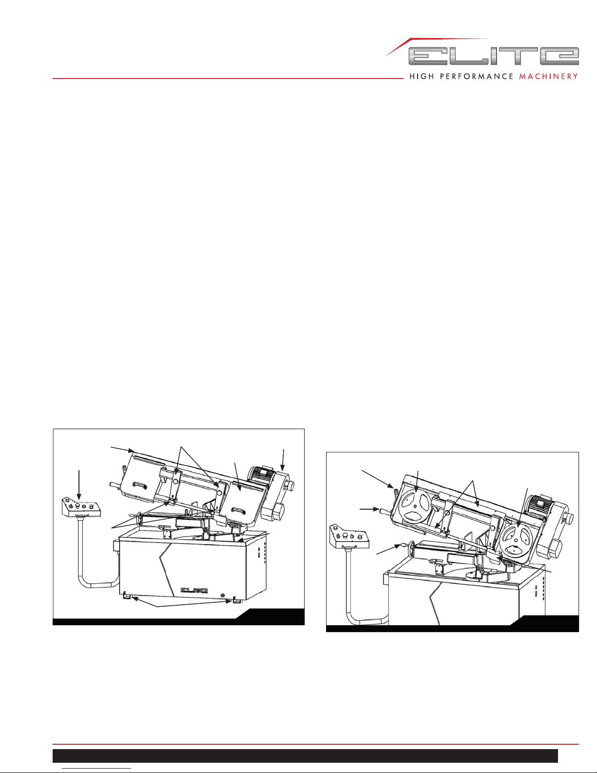
6.0 MACHINE FEATURES
Figures 1 and 2 depict the main features of the Model EHB8 Horizontal Cut-Off Bandsaw. The machine consists of a
machine base onto which is installed a saw head.
6.1 MACHINE BASE
The machine base consists of a coolant collection pan
mounted on two panels that form the legs of the machine.
A shelf is provided under the collection pan that supports a
coolant tank.
The machine bed mounts on the top of the collection pan.
The bed supports the vise and the vise-tightening lead
screw.
The coolant tank is equipped with a pump/motor assembly.
The pump/motor circulates coolant through tubing to cool
and lubricate the saw blade, the blade guides, and the
workpiece.
A drainpipe is provided to connect the collection pan to
the coolant tank. A screen is provided in the collection
pan to screen-out cutting debris as the coolant drains into
the coolant tank. Coolant is added to the tank by pouring
coolant into the collection pan. The tank is easily removed
from its shelf for cleaning and maintenance.
Saw Head
Control Panel
Guide Bearing Supports
Blade Wheel Cover (2)
Belt Cover
6.2 SAW HEAD
The saw head (Figure 2) consists of a drive motor, drive
pulleys, gearbox, blade wheels, blade guides and supports,
control panel, blade tension/blade tracking mechanism,
wire brush, and the saw blade.
The drive motor is mounted on a pivoting plate that swings
outward to provide drive belt tension. The motor is fitted
with a step pulley; the drive belt connects to a second step
pulley that is mounted on the input shaft of the gearbox.
A speed-reducing gearbox is mounted on the back side of
the blade wheel box on the right side of the machine. The
blade wheel (drive wheel) is installed on the output shaft of
the gearbox.
A second blade wheel is located in a blade wheel box on
the left of the machine. The blade wheel (driven wheel) is
mounted on a shaft that is part of the blade tension/tracking
mechanism. The blade tension mechanism is used to
tighten the saw blade on the blade wheels.
The mechanism also has adjustment screws that enable
the saw blade to “track” evenly on the blade wheels. The
adjustment screws change the angle of the driven blade
wheel shaft so the wheels are aligned. Tracking adjustments
are generally made after the saw blade is changed but may
be required periodically due to wear over time.
Blade
Tension
Handwheel
Driven Wheel
Blade Guards
Drive Wheel
Guide
Bearing
Housing
Floor Anchor Brackets
EHB-8VS | EHB-8VSM
Coolant
Drain
Screen
Fig. 1
Lifting
Handle
Vise
Handwheel
Chip
Brush
Cover
Fig. 2
7
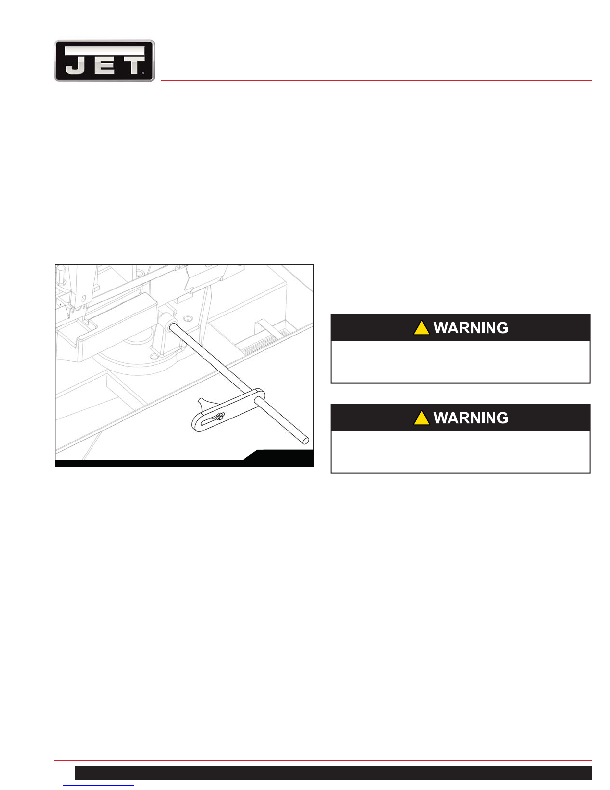
6.3 WORK STOP
A work stop (refer to Figure 3) is provided with the machine
to allow cutting multiple pieces of identical length (refer to
Figure 12). The stop consists of a rod onto which is installed
a stop bracket, a tapered stop, a clamping knob and a
locking handle. The rod is installed in a bore in the front
of the saw bed. The stop bracket is positioned on the rod
with the tapered stop toward the end of the workpiece. The
bracket is moved in or out on the rod to establish the length
of the workpiece.
7.0 UNPACKING AND ASSEMBLY
7.1 MACHINE SETUP
The cut-off saw has been pre-adjusted at the factory and
several test pieces have been cut to verify cutting accuracy .
Remove the saw from the shipping skid; discard any holddown devices. Place the saw on the shop floor; secure the
saw to the floor using mounting anchors secured through
four holes in the machine base. (Refer to Figure 1 for floor
anchor bracket location). If the saw will be used to cut long
pieces of stock, allow plenty of room for the length of the
stock.
8.0 ELECTRICAL CONNECTION
!
Electrical connection must be made by a licensed
electrician. The wiring methods and practices must
comply with local electrical codes.
Fig. 3
6.4 CONTROL PANEL
The control panel is mounted on a movable arm to the left
of the saw. Refer to the Controls and Indicators section
(section 9.0) for a description of the controls.
6.5 AUXILIARY COOLANT HOSE
Your saw is equipped with an auxiliary coolant hose. This
can be used when a large amount of coolant needs to be
directed at the work piece.
!
The machine uses high voltage electrical power
that poses a significant risk of serious injury or
death if proper precautions are not observed.
Connect the machine to the electrical power branch circuit
(refer to the Wiring Diagram section 19.0). Observe the
following guidelines when connecting the saw to the power
source:
1. Make sure the saw is disconnected from the electrical
power branch circuit (trip the required circuit breakers
or remove the required fuses).
2. Place a warning placard or tag on the service panel
to prevent accidental electrical shock.
3. When installing the motor power cord into a
receptacle, make sure the plug is compatible with the
receptacle.
4. When using hard-wired connections, connect the
wires as shown in the Wiring Diagram section.
5. Install the fuses or reset the breakers.
Check operation of the saw.
8
8-in x 13-in Horizontal Cut-Off Bandsaw
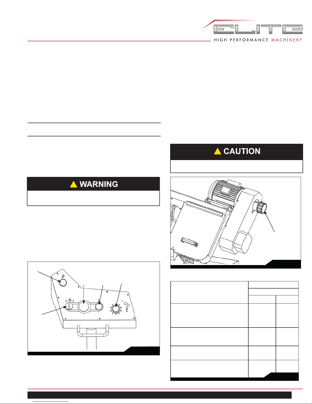
9.0 CONTROLS AND INDICATORS
9.1 CONTROL PANEL
The operating controls for the cut-off saw are located on the
control panel (Figure 4) and consist of the following controls
and indicators:
Coolant Pump Switch (A) – turns coolant pump on and off.
Emergency Stop Switch (B) – press to stop the drive
motor.
Note: A micro switch also stops the motor when the
workpiece is cut and the saw head is completely down.
Start Switch (C) – press to start the drive motor. The saw
head must be in the raised position.
Power Light (D) – indicates that machine is plugged in and
the outlet circuit breaker is turned on. The machine does not
need to be running for the power light to be on.
!
If the bulb is out, lamp will not light, but machine
may still have power.
9.2 BLADE SPEEDS
The Model EHB-8 horizontal cut-off bandsaw is equipped
with electronic variable speed raging from 80-310 FPM. The
speed change is completed by turning the speed control
knob (Figure 5) located to the right of the machine on the
main motor. Change blade speeds as follows:
1. Raise the saw head so that it is not in contact with a
work piece.
2. Press the motor start button on the main control panel.
3. Adjust the speed to correspond with the material that
you are cutting (Figure 6 on page 9) Note: speeds
are approximate.
!
Adjust speed dial only when machine is running.
Feed Rate Control (E) – this knob is used to set the
amount of downward force that is applied to the saw blade.
The feed rate is proportional to the opening of the valve.
When set to zero, the saw head is locked in the raised
position. Increasing the valve opening (counterclockwise
adjustment) increases the feed rate; decreasing the valve
opening (clockwise adjustment) reduces the feed rate.
D
B
A
C
E
Fig. 4
Speed Rate Control Knob
Material to be Cut Belt Speed
60 Hz
fpm mpm
Tool Steel, Stainless Steel, Alloy
~80 25
Steel, Phosphor Bronze, Hard
Bonze, Hard Cast Iron, Malleable Iron
Mild Steel, Soft Cast Iron, Me-
~130 40
dium Hard Brass, Medium Hard
Bronze
Soft Brasses and Bronzes, Hard
~170 51
Aluminum, Plastics
Plastics, Soft and Medium Alu-
~235 71
minum, Wood, Other Light Materials
Fig. 5
Fig. 6
EHB-8VS | EHB-8VSM
9
10.0 BLADE SELECTION
The cut-off saw is delivered with a saw blade that is
adequate for a variety of cut-off jobs on a variety of common
materials.
Refer to Figure 6 for the speeds recommended for various
materials. These speeds, while appropriate for many
common shop cutting needs, do not encompass the wide
variety of special blade configurations (tooth pitch and set)
and special alloys for cutting unusual or exotic materials.
A coarse blade could be used for a solid steel bar, but a
finer tooth blade would be used on a thin-wall steel tube.
In general, the blade choice is determined by the thickness
of the material; the thinner the materials; the finer the tooth
pitch.
A minimum of three teeth should be on the workpiece at all
times for proper cutting. The blade and workpiece can be
damaged if the teeth are so far apart that they straddle the
workpiece.
For very high production on cutting of special materials, or
difficult to cut materials such as stainless steel, tool steel,
or titanium, you can ask your industrial distributor for more
specific blade recommendations. The supplier that provides
the workpiece material should be able to provide you with
very specific instructions regarding the best blade (and
coolant or cutting fluid, if needed) for the material or shape
supplied.
10.1 BLADE BREAK-IN PROCEDURES
New blades are very sharp and, therefore, have a tooth
geometry that is easily damaged if a careful break-in
procedure is not followed. Consult the blade manufacturer’s
literature for break-in of specific blades on specific materials.
However, the following procedure will be adequate for breakin of Jet-supplied blades on lower alloy ferrous materials:
1. Clamp a section of round stock in the vise. The stock
should be 2 inches or larger in diameter.
2. Operate the saw at low speed. Start the cut with a
very light feed rate.
3. When the saw has completed 1/3 of the cut, increase
the feed rate slightly and allow the saw to complete
the cut.
4. Keep the hydraulic cylinder needle valve in the same
position and begin a second cut on the same or
similar workpiece.
5. When the blade has completed about 1/3 of the cut,
increase the feed rate.
Watch the chip formation until cutting is at its most
efficient rate and allow the saw to complete the cut
(refer to Evaluating Cutting Efficiency section 11.2).
The blade is now considered ready for use.
11.0 OPERATIONS
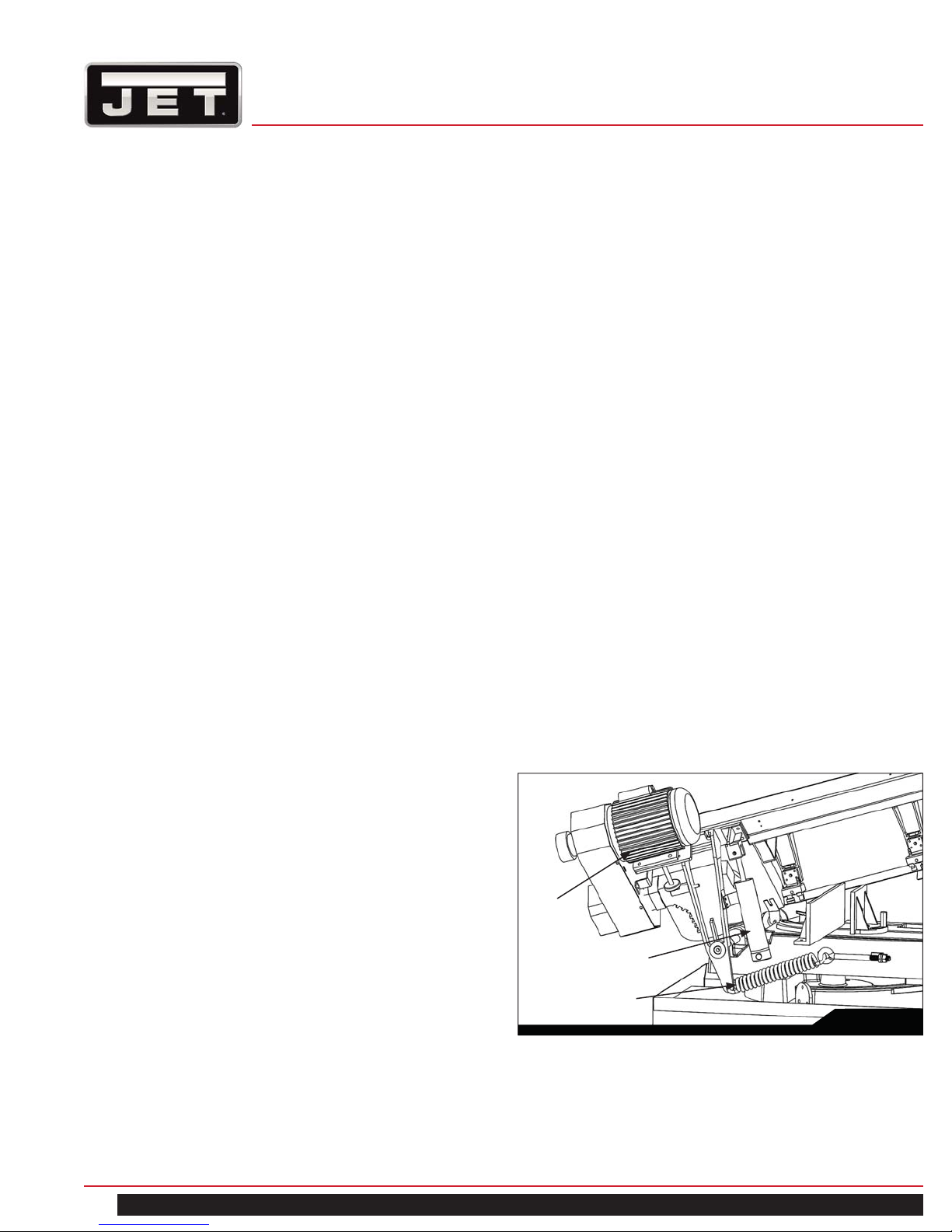
11.1 HYDRAULIC FEED CONTROL
The weight of the saw head provides the force needed to
cut through the workpiece. The cut-off saw has a hydraulic
cylinder that controls the feed rate of the saw.
The hydraulic feed control circuit consists of a single acting
hydraulic cylinder (Figure 7) and a feed rate control (Figure
4). The feed control cylinder resists motion in the downward
direction to control the feed rate. The control cylinder offers
no resistance when raised upward.
The feed rate control knob (Figure 4) controls the rate at
which the saw head is lowered. The control knob (needle
valve) controls the rate at which the hydraulic fluid is
released from the hydraulic cylinder. When the needle
valve is closed, the cylinder is locked. With the needle valve
slightly open, the cylinder permits slow, or light, downward
force. Opening the needle valve further increases the feed
rate and applies more force to the saw blade and workpiece.
The needle valve is adjusted until the saw is operating efficiently. The efficiency of operation is usually evaluated
by observing chip formation. Blade efficiency is further described on the following page.
Drive
Motor
Hydraulic Cylinder
Counterweight Spring
Fig. 7
10
8-in x 13-in Horizontal Cut-Off Bandsaw
11.2 EVALUATING CUTTING EFFICIENCY
Is the blade cutting efficiently? The best way to determine
this is to observe the chips formed by the cutting blade.
If the chip formation is powdery, then the feed is much too
light, or the blade is dull.
If the chips formed are curled, but colored – blue or straw
colored from heat generated during the cut – then the feed
rate is too high.
If the chips are slightly curled and are not colored by heat
– the blade is sufficiently sharp and is cutting at its most
efficient rate.
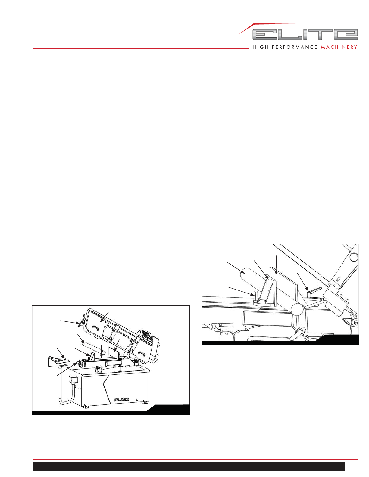
11.3 WORK SETUP
Referring to Figure 8:
1. Set the feed rate control knob (C) to zero.
2. With the lifting handle (A) raise the saw head (B).
3. Turn the vise handwheel (D) counter clock-wise
enough to free the moveable vise jaw (E). Then
pull the moveable vise jaw away from the fixed vise
jaw(H).
4. Place the workpiece (F) on the work table (G). For
long workpieces, provide support at the other end. If
necessary, provide additional downward clamping to
hold the workpiece securely on the worktable.
5. Clamp the workpiece (F) in the vise by first pushing
the moveable vise jaw (E) against the workpiece.
Then rotate the vise handwheel (D) clockwise to
secure the workpiece.
11.4 SETTING THE VISE FOR ANGLE CUTS
(NON-MITERING VERSION ONLY)
Referring to Figure 9, the vise can be adjusted through a
45-degree arc as follows:
1. Loosen the lock handle (E) that secures the fixed vise
jaw (D).
2. Rotate the fixed vise jaw (D) to the desired angle,
setting it to the scale on the back edge of the table.
For accurate cuts, use a variable protractor to set the
position of the jaw, aligning one side of the protractor
with the blade.
3. Tighten the lock handle (E).
4. Loosen the hex head bolt (A) on the moveable vise
jaw (C).
5. Place the workpiece (B) between the vise jaws (C, D).
6. Set the moveable vise jaw (C), pressing it against the
side of the workpiece (B) and fixed vise jaw (D).
7. Tighten the hex head bolt (A) on the moveable vise
jaw to secure the jaw.
B
A
C
D
E
B
A
F
C
E
D
EHB-8VS | EHB-8VSM
G
H
Fig. 9
Fig. 8
11
 Loading...