

Operating Instructions and Parts Manual
Horizontal Band Saw
Models EHB-1018VM | EHB-1018VMH
®
JET
427 New Sanford Road
LaVergne, Tennessee 37086
www.jettools.com
Ph.: 855-336-4032
Part No. M-891070
REV C2 09/2018
Copyright © 2018 JET
1

1.0 WARRANTY AND SERVICE
JET® warrants every product it sells against manufacturers’ defects. If one of our tools needs service or repair, please
contact Technical Service by calling 1-855-336-4032, 8AM to 5PM CST, Monday through Friday.
WARRANTY PERIOD
The general warranty lasts for the time period specifi ed in the literature included with your product or on the offi cial JET
branded website, jettools.com.
WHO IS COVERED?
This warranty covers only the initial purchaser of the product from the date of delivery.
WHAT IS COVERED?
This warranty covers any defects in workmanship or materials subject to the limitations stated below. This warranty does not
cover failures due directly or indirectly to misuse, abuse, negligence or accidents, normal wear-and-tear, improper repair,
alterations or lack of maintenance.
HOW TO GET TECHNICAL SUPPORT
Please contact Technical Service by calling 1-855-336-4032. Please note that you will be asked to provide proof of initial
purchase when calling. If a product requires further inspection, the Technical Service representative will explain and assist
with any additional action needed. JET has Authorized Service Centers located throughout the United States. For the name
of an Authorized Service Center in your area call 1-855-336-4032 or use the Service Center Locator on the JET website.
2
Horizontal Band Saw

MORE INFORMATION
JET® is constantly adding new products. For complete, up-to-date product information, check with your local distributor or
visit the JET website, jettools.com.
HOW STATE LAW APPLIES
This warranty gives you specifi c legal rights, subject to applicable state law.
LIMITATIONS ON THIS WARRANTY
JET LIMITS ALL IMPLIED WARRANTIES TO THE PERIOD OF THE LIMITED WARRANTY FOR EACH PRODUCT.
EXCEPT AS STA TED HEREIN, ANY IMPLIED WARRANTIES OF MERCHANT ABILITY AND FITNESS FOR A P ARTICULAR
PURPOSE ARE EXCLUDED. SOME STATES DO NOT ALLOW LIMITATIONS ON HOW LONG AN IMPLIED WARRANTY
LASTS, SO THE ABOVE LIMITATION MAY NOT APPLY TO YOU.
JET SHALL IN NO EVENT BE LIABLE FOR DEATH, INJURIES TO PERSONS OR PROPERTY, OR FOR INCIDENTAL,
CONTINGENT, SPECIAL, OR CONSEQUENTIAL DAMAGES ARISING FROM THE USE OF OUR PRODUCTS. SOME
STATES DO NOT ALLOW THE EXCLUSION OR LIMITATION OF INCIDENTAL OR CONSEQUENTIAL DAMAGES, SO
THE ABOVE LIMITATION OR EXCLUSION MAY NOT APPLY TO YOU.
JET sells through distributors only . The specifi cations listed in JET printed materials and on offi cial JET website are given as
general information and are not binding. JET reserves the right to effect at any time, without prior notice, those alterations
to parts, fi ttings, and accessory equipment which they may deem necessary for any reason whatsoever. JET® branded
products are not sold in Canada by JPW Industries, Inc.
NOTE: JET is a division of JPW Industries, Inc. References in this document to JET also apply to JPW Industries, Inc., or
any of its successors in interest to the JET brand.
EHB-1018VM | EHB-1018VMH
3

2.0 TABLE OF CONTENTS
1.0 WARRANTY AND SERVICE .........................................................................................................................................2
2.0 TABLE OF CONTENTS .................................................................................................................................................4
3.0 SAFETY WARNINGS ....................................................................................................................................................4
4.0 INTRODUCTION ...........................................................................................................................................................6
5.0 SPECIFICATIONS .........................................................................................................................................................6
6.0 UNCRATING AND ASSEMBL Y .................................................................................................... .................................7
7.0 INSTALLATION .............................................................................................................................................................7
8.0 ELECTRICAL CONNECTIONS .....................................................................................................................................7
9.0 CONTROLS...................................................................................................................................................................7
10.0 AUXILIARY COOLANT HOSE.....................................................................................................................................8
11.0 PRIOR TO OPERATION ..............................................................................................................................................8
12.0 OPERATING CONTROLS AND ADJUSTMENTS .......................................................................................................8
12.1 REMOVING AND INSTALLING THE BLADE ..........................................................................................................8
12.2 ADJUSTING BLADE GUIDE BRACKETS ...............................................................................................................9
12.3 ADJUSTING BLADE GUIDE ROLLER BEARINGS ................................................................................................9
12.4 CHANGING BLADE SPEED .................................................................................................................................10
12.5 OPERATING VISE ................................................................................................................................................10
12.5.1 HYDRAULIC VISE .........................................................................................................................................10
12.6 BOW WEIGHT ADJUSTMENT ..............................................................................................................................11
12.7 ADJUSTING STOCK ADVANCE STOP ................................................................................................................11
12.8 SETTING UP THE MACHINE FOR OPERATION .................................................................................................11
12.9 AUTOMA TIC SHUT-OFF .......................................................................................................................................12
12.10 GEAR CASE ........................................................................................................................................................12
12.1 1 ADJUST BLADE TENSION AND BLADE TRACKING ADJUSTMENT ................................................................12
12.12 SAFETY DEVICE FOR BROKEN SAW BLADE ..................................................................................................13
12.13 CLAMPING VISE POSITION LOCKING LEVER ................................................................................................13
12.14 MITER ANGLE ADJUSTMENT ...........................................................................................................................13
13.0 MAINTENANCE ........................................................................................................................................................14
14.0 LUBRICATION ...........................................................................................................................................................14
15.0 REPLACEMENT PARTS ...........................................................................................................................................14
16.0 WIRING DIAGRAM ............................................................................................................................................. 27-28
3.0 SAFETY WARNINGS
1. Read and understand the entire owner’s manual before attempting assembly or operation.
2. Read and understand the warnings posted on the machine and in this manual. Failure to comply with all of these warnings may cause
serious injury.
3. Replace the warning labels if they become obscured or removed.
4. This band saw is designed and intended for use by properly trained and experienced personnel only. If you are not familiar with the
proper and safe operation of a band saw, do not use until proper training and knowledge have been obtained.
5. Do not use this band saw for other than its intended use. If used for other purposes, JET
holds itself harmless from any injury that may result from that use.
6. Always wear approved safety glasses/face shields while using this band saw. Everyday eyeglasses only have impact resistant
lenses; they are not safety glasses.
7. Before operating this band saw, remove tie, rings, watches and other jewelry, and roll sleeves up past the elbows. Remove all loose
clothing and confine long hair. Non-slip footwear or anti-skid floor strips are recommended. Do not wear gloves.
8. Wear ear protectors (plugs or muffs) during extended periods of operation.
9. Do not operate this machine while tired or under the influence of drugs, alcohol or any medication.
4
®
, disclaims any real or implied warranty and
Horizontal Band Saw
10. Make certain the switch is in the OFF position before connecting the machine to the power supply.
11. Make certain the machine is properly grounded.
12. Make all machine adjustments or maintenance with the machine unplugged from the power source.
13. Remove adjusting keys and wrenches. Form a habit of checking to see that keys and adjusting wrenches are removed from the
machine before turning it on.
14. Avoid contact with coolant, especially guarding your eyes.
15. Always keeps hands and fingers away from the blade when the machine is running.
16. Never hand hold the material. Always use the vise and clamp it securely.
17. Always provide adequate support for long and heavy material.
18. Keep safety guards in place at all times when the machine is in use. If removed for maintenance purposes, use extreme caution and
replace the guards immediately after maintenance is complete.
19. Check damaged parts. Before further use of the machine, a guard or other part that is damaged should be carefully checked to
determine that it will operate properly and perform its intended function. Check for alignment of moving parts, binding of moving parts,
breakage of parts, mounting and any other conditions that may affect its operation. A guard or other part that is damaged should be
properly repaired or replaced.
Do not use power tools in damp/wet locations or other dangerous environments. Do not expose them to rain. Keep work area well
20.
lighted. Provide for adequate space surrounding work area and non-glare overhead lighting.
21. Keep the floor around the machine clean and free of scrap material, oil and grease.
Keep visitors a safe distance from the work area. Keep children away. Workshop should be childproof; padlocks, master switches,
22.
remove starter keys.
23. Give your work undivided attention. Looking around, carrying on a conversation and “horse-play” are careless acts that can result in
serious injury.
24. Maintain a balanced stance at all times so that you do not fall or lean against the blade or other moving parts. Do not overreach or
use excessive force to perform any machine operation.
25. Use the right tool at the correct speed and feed rate. Do not force a tool or attachment to do a job for which it was not designed. The
right tool will do the job better and more safely.
26. Use recommended accessories; improper accessories may be hazardous.
27. Maintain tools with care. Keep blade sharp and clean for the best and safest performance. Follow instructions for lubricating and
changing accessories.
28. Maintain proper adjustment of blade tension, blade guides and thrust bearings.
29. Turn off the machine and disconnect from power before cleaning. Use a brush to remove chips or debris — do not use your hands.
30. Do not stand on the machine. Serious injury could occur if the machine tips over.
31. Never leave the machine running unattended. Turn the power off and do not leave the machine until it comes to a complete stop.
32. Be sure that the blade is not in contact with the workpiece when the motor is started. The motor shall be started and you should allow
the saw to come up to full speed before bringing the saw blade into contact with the workpiece.
33. Adjust upper guide to clear workpiece. Hold workpiece fi rmly against table.
34. Direction of feed — feed work into a blade or cutter against the direction of rotation of the blade or cutter only.
35. Installation work and electrical wiring must be done by qualifi ed electrician in accordance with all applicable codes and standards.
36. Do not remove jammed pieces until blade has stopped.
WARNING: This product can expose you to chemicals including lead and benzene which are known to the State of California to
!
cause cancer and birth defects or other reproductive harm. For more information go to http://www.p65warnings.ca.gov.
WARNING: Some dust, fumes and gases created by power sanding, sawing, grinding, drilling, welding and other construction
!
activities contain chemicals known to the State of California to cause cancer and birth defects or other reproductive harm. Some
examples of these chemicals are:
• lead from lead based paint
• crystalline silica from bricks, cement and other masonry products
• arsenic and chromium from chemically treated lumber
Your risk of exposure varies, depending on how often you do this type of work. To reduce your exposure to these chemicals, work
in a well-ventilated area and work with approved safety equipment, such as dust masks that are specifically designed to filter out
microscopic particles. For more information go to http://www.p65warnings.ca.gov/ and http://www.p65warnings.ca.gov/wood.
EHB-1018VM | EHB-1018VMH
5
Familiarize yourself with the following safety notices used in this manual:
!
This means that if precautions are not heeded, it
may result in minor injury and/or possible machine
damage.
This means that if precautions are not heeded, it
may result in serious or even fatal injury.
!
4.0 INTRODUCTION
This manual is provided by JET® covering the safe operation and maintenance procedures for a JET Model EHB-1018VM
or EHB-1018VMH. This manual contains instructions on installation, safety precautions, general operating procedures,
maintenance instructions and parts breakdown. Your machine has been designed and constructed to provide consistent,
long-term operation if used in accordance with the instructions as set forth in this document.
5.0 SPECIFICATIONS
Model Number EHB-1018VM EHB-1018VMH
Stock Number 891070 891080
Capacity (in.):
Round at 90° 10 10
Round at 60° 6 6
Round at 45° 10 10
Rectangle at 90° 10x17 10x17
Rectangle at 60° 6x5 6x5
Rectangle at 45° 10x12 10x12
Square at 90° 10x10 10x10
Square at 60° 5-1/2x5-1/2 5-1/2x5-1/2
Square at 45° 10x10 10x10
Vise Swivel (°) 0 0
Head Movement (°) 60 R, 45 L 60 R, 45 L
Blade Size (in.) 1 x .035 x 144 1 x .035 x 144
Blade Wheel Diameter (in.) 14 14
Blade Wheel Speed (SFPM) Variable 50-275 Variable 50-275
Bed Height (in.) 32 32
Motor (HP) 2 HP, 230/460V 3 Phase
CSA/CUS Certifi ed
Overall Dimensions (in.) 85 x 40 x 44 85 x 40 x 44
Net Weight - approx. (lbs.) 1,166 1,210
Shipping Weight - approx. (lbs.) 1,276 1,320
2 HP, 230/460V 3 Phase
CSA/CUS Certifi ed
The specifi cations in this manual were current at time of publication, but because of our
policy of continuous improvement, JET, reserves the right to change specifi cations at any
time and without prior notice, without incurring obligations.
6
Horizontal Band Saw
6.0 UNCRATING AND ASSEMBLY
Note: Read and understand the entire manual before
attempting setup or operation.
8.0 ELECTRICAL CONNECTIONS
!
1. Finish uncrating the saw and inspect for damage.
Should any have occurred, contact your local distribu tor.
2. Remove all bolts attaching machine to shipping base.
3. Leave packing material between vise clamps and saw
head intact until band saw has been lifted to its fi nal
position.
4. Clean all rust protected surfaces with kerosene or
diesel oil to remove protective coating. Do not use
gasoline, paint thinner, mineral spirits, etc. These may
damage painted surfaces.
5. Lubricate all slideways with SAE 10W oil.
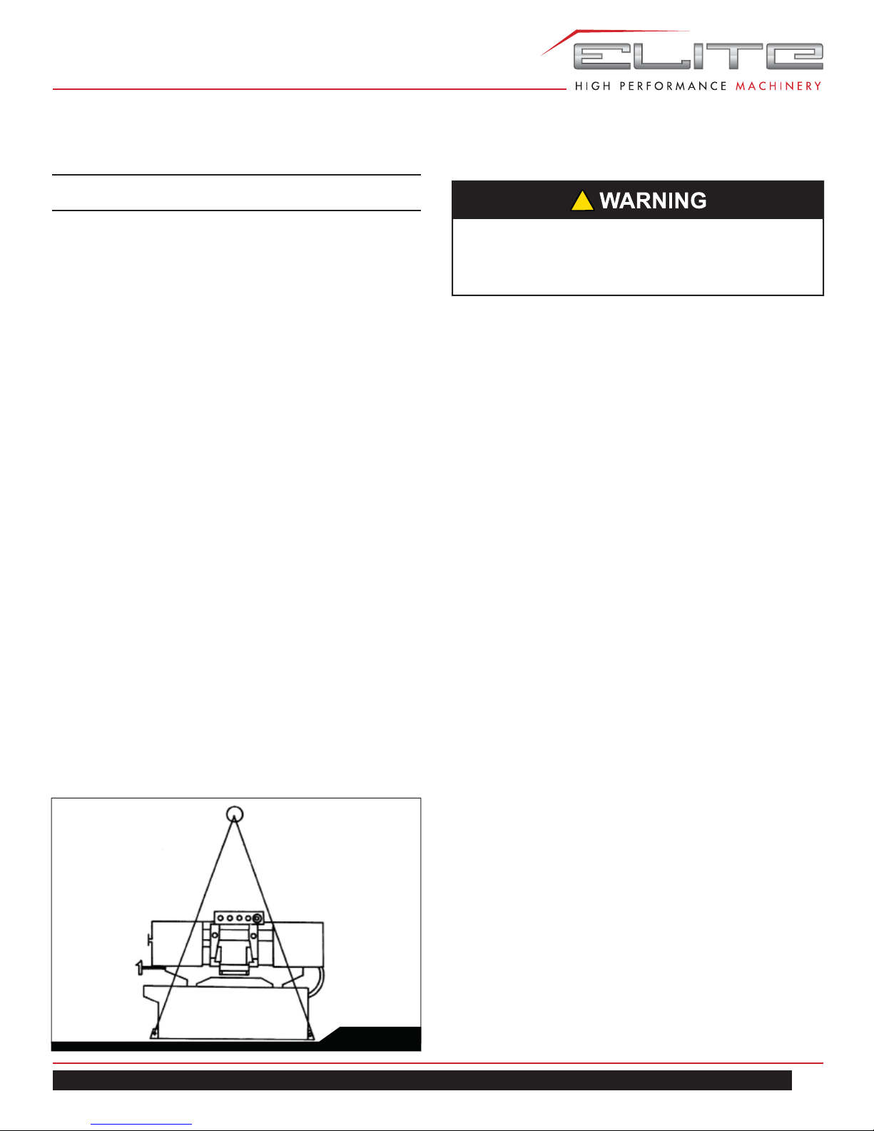
7.0 INSTALLATION
For best performance, the band saw should be located on
a solid and level foundation. Allow room for servicing and
for moving large stock around the band saw when deciding a location for the machine.
1. Using lifting straps that are isolated from the band
saw’s fi nished surfaces, lift machine and place in
desired location. See Figure 1 for strap placement.
2. Install four leveling bolts with lock nuts on both sides
of the base as shown in the parts breakdown on page
16, items 2 and 3.
3. Place a level on the table surface and check side-to-
side and front-to-back.
4. Adjust leveling screws until machine is level in both
directions and tighten locking nuts.
All electrical connections must be done by a
qualifi ed electrician. All adjustments or repairs must
be done with machine disconnected from power
source. Failure to comply may cause serious injury.
The EHB-1018VM/VMH is rated at 230/460V, 3 phase.
Confi rm that power available at the saw’s location match-
es that for which the saw is wired.
If the saw runs backward, disconnect from power and
switch any two of the three power leads.
9.0 CONTROLS
Refer to Figure 2.
Power Indicator Light (A) – lit whenever machine is
running.
Start Button (B) – press to start band saw.
Stop Button (C) – press to stop band saw.
Emergency Stop Button (D) – press to immediately stop
all machine functions.
Blade Up Button (E) – when in automatic mode, press to
raise saw head.
Blade Down Button (F) – when in Automatic mode, press
to lower saw head.
Coolant Switch (G) – Turn arrow to “I” to turn on coolant
fl ow. Turn arrow to “O” to stop coolant fl ow.
Manual/Auto Switch (H) – due to saw head weight, use
the auto mode to raise and lower saw head.
Hydraulic Vise Closed Button (I) – press to close vise.
Hydraulic Vise Open Button (J) – press to open vise.
Saw Head Down Feed Speed Control (K) – this knob is
used to set the amount of downward force that is applied
to the saw blade. The feed rate is proportional to the
opening of the valve. When set to zero, the saw head is
locked in the raised position. Increasing the valve opening
(counterclockwise adjustment) increases the feed rate;
decreasing the valve opening (clockwise adjustment)
reduces the feed rate.
EHB-1018VM | EHB-1018VMH
Fig. 1
7
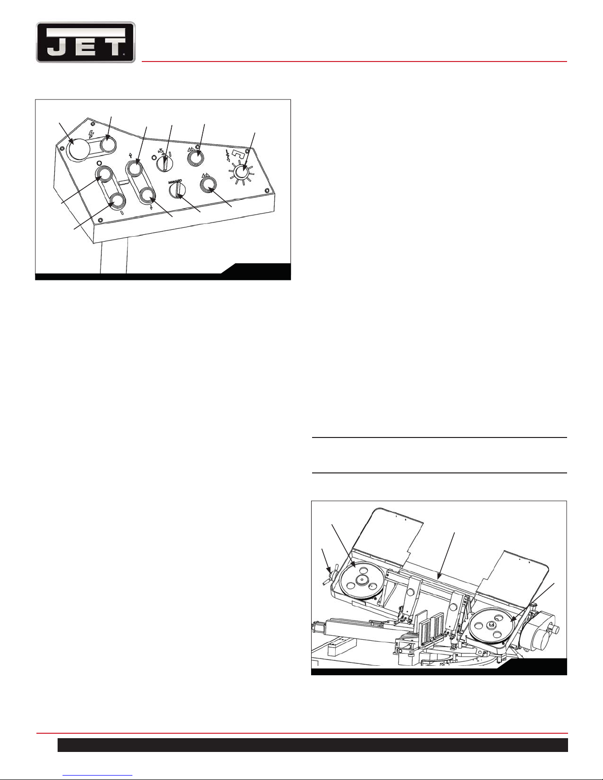
D
A
G
E
I
K
12.0 OPERATING CONTROLS AND
ADJUSTMENTS
12.1 REMOVING AND INSTALLING THE BLADE
1. Disconnect the machine from the power source.
C
H
B
F
J
Fig. 2
10.0 AUXILIARY COOLANT HOSE
Your saw is equipped with an auxiliary coolant hose. This
can be used when a large amount of coolant needs to be
directed at the work piece.
11.0 PRIOR TO OPERATION
1. Check that blade tooth direction matches diagram on
blade guides.
2. Check to see that blade is properly seated on wheels
after applying correct tension (approximately 25,000
lbs.).
3. Set blade holder guides for approximately .003” to
.005” clearance between guides and blade.
4. Check for slight clearance between back up rollers
and back of blade.
5. Position blade guides as close to workpiece as pos-
sible.
6. Select proper speed and feed rate for material being
cut.
7. Material to be cut must be securely held in vise.
8. Check to see that coolant level is adequate and turn
on coolant pump if material to be cut requires it.
Machine should be fi lled with four gallons of the
proper coolant mixture. Follow the directions on the
product maker’s label and fi ll the coolant tank
through the chip tray area.
9. Do not start cut on a sharp edge.
10. Keep machine lubricated. See “Lubrication” section.
2. Raise the saw frame about 6” and close the feed rate
lever by turning it clockwise as far as it will go.
3. Open both wheel covers and clean the swarf out of
the machine.
4. Release blade tension by turning the blade tension
handwheel (C) Fig. 3 counterclockwise.
5. Remove the blade from both wheels and out of each
blade guide.
6. Make sure the teeth of the new blade are pointing in
the direction of travel. If necessary, turn the
blade inside out.
7. Place the blade in place on the wheels (A) and
through the upper blade guard (B) Fig. 3 is shown
with the wheel covers removed for clarity.
8. Work the blade (F) all the way up into the blade guide
roller bearings (D) with the back of the blade against
the back-up bearing (E), as shown in Fig. 4.
NOTE: If roller bearings need adjusting refer to
the section ADJUSTING BLADE GUIDE ROLLER
BEARINGS.
A
B
C
A
Fig. 3
8
Horizontal Band Saw
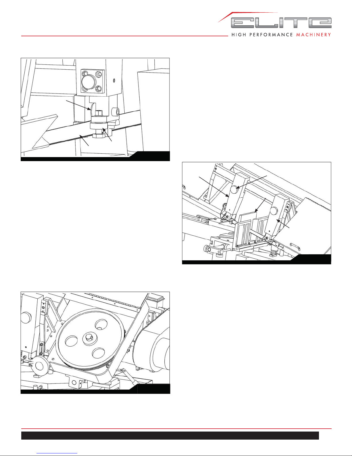
12.2 ADJUSTING BLADE GUIDE BRACKETS
The blade guides should be set as close to the vise jaw as
possible. The right blade guide bracket (A) Fig. 6, is not
E
F
D
Fig. 4
adjustable and is set at the factory to clear the right hand
vise jaw. The left blade guide bracket (B) can be moved
to the left or right depending on the position of the left
hand vise jaw (C).
To move the left blade guide bracket (B), loosen hand
knob (D), position blade guide bracket (B) and tighten
hand knob (D).
9. Put light tension on the blade and work it on both
wheels, as shown in Fig. 5.
MAKE SURE THAT THE BACK OF THE BLADE
IS AGAINST THE WHEEL FLANGES OF
BOTH WHEELS. THIS IS VERY IMPORTANT.
10. When you are sure the back of the blade is against
the wheel fl anges of both wheels and properly insert-
ed into the guides, fi nish putting tension on the blade.
11. Jog the power “on” and “off” to be sure the blade is in
place and tracking properly.
If blade is not tracking properly refer to the section
“Tracking the Blade”.
Fig. 5
B
D
C
A
Fig. 6
12.3 ADJUSTING BLADE GUIDE ROLLER
BEARINGS
The back of the blade (A) Fig. 7, should ride against the
back-up support bearing (B) which is positioned at an
angle so as to provide greater bearing support, eliminating
bearing wear and extending blade life.
The saw blade (A) should also ride between the two roller
bearings (C) and (D) Fig. 7.
The rear bearing (C) on the left hand blade guide can be
easily adjusted to suit blade thickness by loosening nut
(E). The bearing (C) is on an eccentric which enables it to
be adjusted for blade thickness in the same manner with
the exception that the adjustable roller bearing is in the
forward position.
Part (F) shown Fig. 8 is a tungsten carbide block, after
completing the adjustments shown in Fig. 7, tighten the
Part (F) onto the surface of the saw blade.
EHB-1018VM | EHB-1018VMH
9
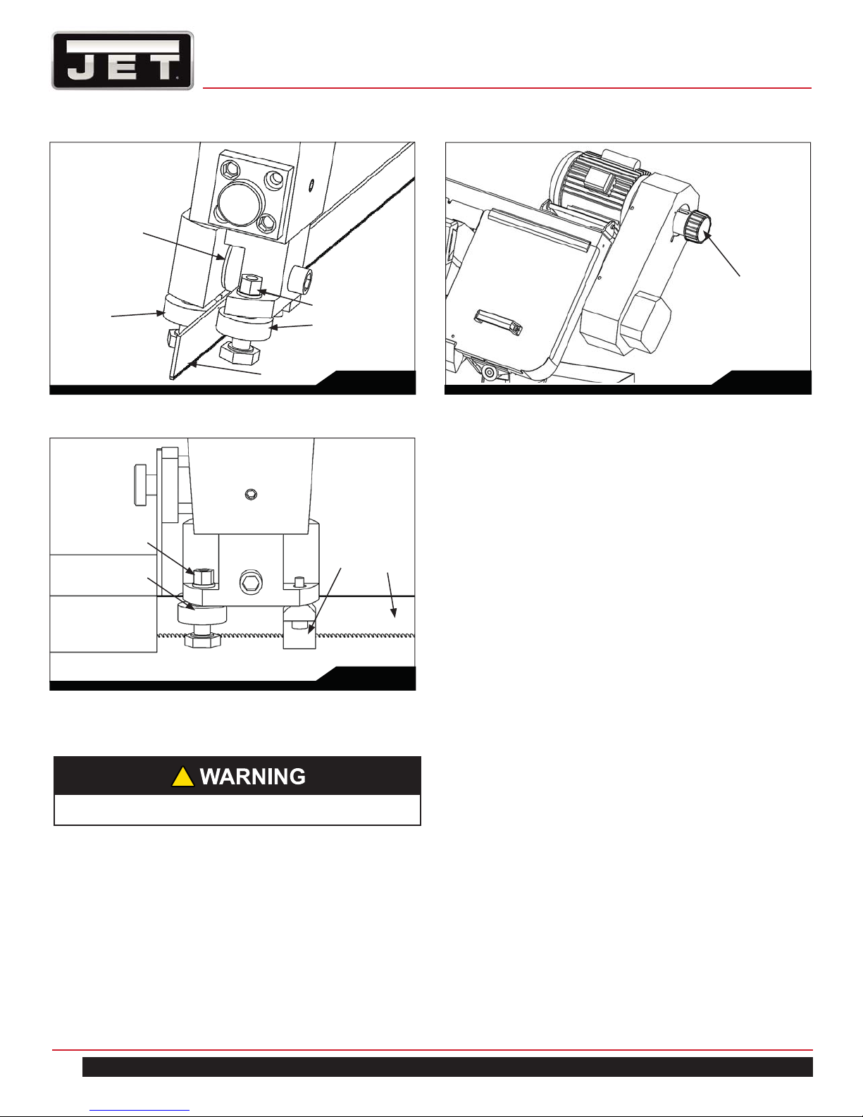
B
Speed Adjuster Knob
C
E
D
A
E
C
Fig. 7
F
Fig. 8
12.4 CHANGING BLADE SPEED
!
Only adjust speed with power on and blade turning.
Fig. 9
12.5 OPERATING VISE
The workpiece is placed between the vise jaws with the
required amount to be cut-off extending out past the blade.
To position the moveable vise jaw (B) instantly, simply turn
vise handknob (A) Fig. 10, counterclockwise 1/2 turn and
move the vise jaw (B) to the desired position.
A
Then tighten vise by turning the knob (A) clockwise.
The vise can be adjusted to cut any angle from 0° to 45°
by loosening the two bolts (C) Fig, 10, on each vise jaw.
Position the vise jaws to the desired angle and tighten the
bolts. It is also necessary, when angle cutting, to move
the right hand vise jaw (D) to the left until the workpiece
and right hand vise jaw clears the right hand guide arm.
12.5.1 HYDRAULIC VISE
The 1018VMH is equipped with a hydraulic vise. This
feature allows the operator to make repeated cuts much
quicker than saws with manual vise.
To use the hydraulic vise, load material as normal and
manually advance the mobile vise jaw against the work
piece then use the vise close and open fuctions located on
the control panel.
1. Raise cutting head approximately six inches above
work piece and turn feed rate knob to zero.
2. Turn power on and turn speed adjuster knob (as in
Figure 9) to match appropriate material.
10
Horizontal Band Saw
 Loading...