

Page 1
Operating Instructions and Parts Manual
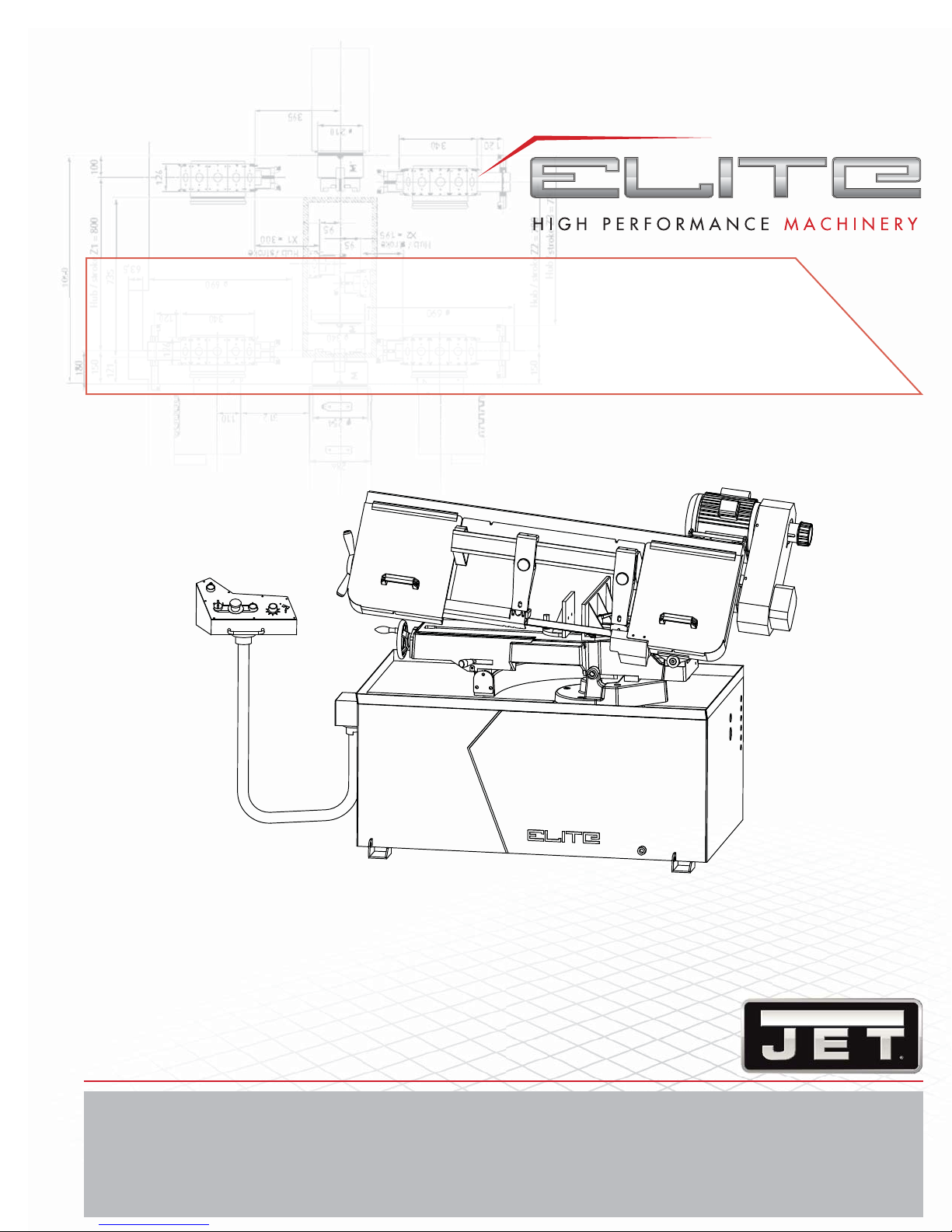
Horizontal Band Saw
Models EHB-916V | EHB-1018V
®
JET
427 New Sanford Road
LaVergne, Tennessee 37086
www.jettools.com
Ph.: 855-336-4032
Part No. M-891050
REV C 11/2016
Copyright © 2016 JET
Page 2

1.0 WARRANTY AND SERVICE
JET® warrants every product it sells against manufacturers’ defects. If one of our tools needs service or repair, please
contact Technical Service by calling 1-855-336-4032, 8AM to 5PM CST, Monday through Friday.
WARRANTY PERIOD
The general warranty lasts for the time period specifi ed in the literature included with your product or on the offi cial JET
branded website, jettools.com.
WHO IS COVERED?
This warranty covers only the initial purchaser of the product from the date of delivery.
WHAT IS COVERED?
This warranty covers any defects in workmanship or materials subject to the limitations stated below. This warranty does not
cover failures due directly or indirectly to misuse, abuse, negligence or accidents, normal wear-and-tear, improper repair,
alterations or lack of maintenance.
HOW TO GET TECHNICAL SUPPORT
Please contact Technical Service by calling 1-855-336-4032. Please note that you will be asked to provide proof of initial
purchase when calling. If a product requires further inspection, the Technical Service representative will explain and assist
with any additional action needed. JET has Authorized Service Centers located throughout the United States. For the name
of an Authorized Service Center in your area call 1-855-336-4032 or use the Service Center Locator on the JET website.
2
Horizontal Band Saw
Page 3

MORE INFORMATION
JET® is constantly adding new products. For complete, up-to-date product information, check with your local distributor or
visit the JET website, jettools.com.
HOW STATE LAW APPLIES
This warranty gives you specifi c legal rights, subject to applicable state law.
LIMITATIONS ON THIS WARRANTY
JET LIMITS ALL IMPLIED WARRANTIES TO THE PERIOD OF THE LIMITED WARRANTY FOR EACH PRODUCT.
EXCEPT AS STA TED HEREIN, ANY IMPLIED WARRANTIES OF MERCHANT ABILITY AND FITNESS FOR A P ARTICULAR
PURPOSE ARE EXCLUDED. SOME STATES DO NOT ALLOW LIMITATIONS ON HOW LONG AN IMPLIED WARRANTY
LASTS, SO THE ABOVE LIMITATION MAY NOT APPLY TO YOU.
JET SHALL IN NO EVENT BE LIABLE FOR DEATH, INJURIES TO PERSONS OR PROPERTY, OR FOR INCIDENTAL,
CONTINGENT, SPECIAL, OR CONSEQUENTIAL DAMAGES ARISING FROM THE USE OF OUR PRODUCTS. SOME
STATES DO NOT ALLOW THE EXCLUSION OR LIMITATION OF INCIDENTAL OR CONSEQUENTIAL DAMAGES, SO
THE ABOVE LIMITATION OR EXCLUSION MAY NOT APPLY TO YOU.
JET sells through distributors only . The specifi cations listed in JET printed materials and on offi cial JET website are given as
general information and are not binding. JET reserves the right to effect at any time, without prior notice, those alterations
to parts, fi ttings, and accessory equipment which they may deem necessary for any reason whatsoever. JET® branded
products are not sold in Canada by JPW Industries, Inc.
NOTE: JET is a division of JPW Industries, Inc. References in this document to JET also apply to JPW Industries, Inc., or
any of its successors in interest to the JET brand.
EHB-916V | EHB-1018V
3
Page 4

2.0 TABLE OF CONTENTS
1.0 WARRANTY AND SERVICE .........................................................................................................................................2
2.0 TABLE OF CONTENTS .................................................................................................................................................4
3.0 SAFETY WARNINGS ....................................................................................................................................................5
4.0 INTRODUCTION ...........................................................................................................................................................6
5.0 SPECIFICATIONS .........................................................................................................................................................6
6.0 UNCRATING AND ASSEMBL Y .................................................................................................... .................................7
7.0 INSTALLATION .............................................................................................................................................................7
8.0 ELECTRICAL CONNECTIONS .....................................................................................................................................7
9.0 CONTROLS...................................................................................................................................................................8
10.0 AUXILIARY COOLANT HOSE.....................................................................................................................................8
11.0 PRIOR TO OPERATION ..............................................................................................................................................8
12.0 OPERATING CONTROLS AND ADJUSTMENTS .......................................................................................................8
12.1 REMOVING AND INSTALLING THE BLADE ..........................................................................................................8
12.2 ADJUSTING BLADE GUIDE BRACKETS ...............................................................................................................9
12.3 ADJUSTING BLADE GUIDE ROLLER BEARINGS ..............................................................................................10
12.4 CHANGING BLADE SPEED .................................................................................................................................10
12.5 OPERATING VISE ................................................................................................................................................10
12.6 BOW WEIGHT ADJUSTMENT ..............................................................................................................................11
12.7 ADJUSTING STOCK ADVANCE STOP ................................................................................................................11
12.8 SETTING UP THE MACHINE FOR OPERATION .................................................................................................11
12.9 AUTOMA TIC SHUT-OFF .......................................................................................................................................12
12.10 GEAR CASE ........................................................................................................................................................12
12.1 1 ADJUST BLADE TENSION AND BLADE TRACKING ADJUSTMENT ................................................................12
13.0 MAINTENANCE ........................................................................................................................................................13
14.0 LUBRICATION ...........................................................................................................................................................13
15.0 REPLACEMENT PARTS ...........................................................................................................................................13
16.0 WIRING DIAGRAM ...................................................................................................................................................34
4
Horizontal Band Saw
Page 5

3.0 SAFETY WARNINGS
1. Read and understand the entire owner’s manual before attempting assembly or operation.
2. Read and understand the warnings posted on the machine and in this manual. Failure to comply with all of these warnings may cause
serious injury.
3. Replace the warning labels if they become obscured or removed.
4. This band saw is designed and intended for use by properly trained and experienced personnel only. If you are not familiar with the
proper and safe operation of a band saw, do not use until proper training and knowledge have been obtained.
5. Do not use this band saw for other than its intended use. If used for other purposes, JET
holds itself harmless from any injury that may result from that use.
6. Always wear approved safety glasses/face shields while using this band saw. Everyday eyeglasses only have impact resistant
lenses; they are not safety glasses.
7. Before operating this band saw, remove tie, rings, watches and other jewelry, and roll sleeves up past the elbows. Remove all loose
clothing and confine long hair. Non-slip footwear or anti-skid floor strips are recommended. Do not wear gloves.
8. Wear ear protectors (plugs or muffs) during extended periods of operation.
9. Some dust created by power sanding, sawing, grinding, drilling and other construction activities contain chemicals known to cause
cancer, birth defects or other reproductive harm. Some examples of these chemicals are:
• Lead from lead based paint.
• Crystalline silica from bricks, cement and other masonry products.
• Arsenic and chromium from chemically treated lumber.
Your risk of exposure varies, depending on how often you do this type of work. To reduce your exposure to these chemicals, work in
a well-ventilated area and work with approved safety equipment, such as face or dust masks that are specifically designed to filter
out microscopic particles.
10. Do not operate this machine while tired or under the influence of drugs, alcohol or any medication.
11. Make certain the switch is in the OFF position before connecting the machine to the power supply.
12. Make certain the machine is properly grounded.
13. Make all machine adjustments or maintenance with the machine unplugged from the power source.
14. Remove adjusting keys and wrenches. Form a habit of checking to see that keys and adjusting wrenches are removed from the
machine before turning it on.
15. Avoid contact with coolant, especially guarding your eyes.
16. Always keeps hands and fingers away from the blade when the machine is running.
17. Never hand hold the material. Always use the vise and clamp it securely.
18. Always provide adequate support for long and heavy material.
19. Keep safety guards in place at all times when the machine is in use. If removed for maintenance purposes, use extreme caution and
replace the guards immediately after maintenance is complete.
20. Check damaged parts. Before further use of the machine, a guard or other part that is damaged should be carefully checked to
determine that it will operate properly and perform its intended function. Check for alignment of moving parts, binding of moving parts,
breakage of parts, mounting and any other conditions that may affect its operation. A guard or other part that is damaged should be
properly repaired or replaced.
Do not use power tools in damp/wet locations or other dangerous environments. Do not expose them to rain. Keep work area well
21.
lighted. Provide for adequate space surrounding work area and non-glare overhead lighting.
22. Keep the floor around the machine clean and free of scrap material, oil and grease.
Keep visitors a safe distance from the work area. Keep children away. Workshop should be childproof; padlocks, master switches,
23.
remove starter keys.
24. Give your work undivided attention. Looking around, carrying on a conversation and “horse-play” are careless acts that can result in
serious injury.
25. Maintain a balanced stance at all times so that you do not fall or lean against the blade or other moving parts. Do not overreach or
use excessive force to perform any machine operation.
26. Use the right tool at the correct speed and feed rate. Do not force a tool or attachment to do a job for which it was not designed. The
right tool will do the job better and more safely.
27. Use recommended accessories; improper accessories may be hazardous.
28. Maintain tools with care. Keep blade sharp and clean for the best and safest performance. Follow instructions for lubricating and
changing accessories.
29. Maintain proper adjustment of blade tension, blade guides and thrust bearings.
30. Turn off the machine and disconnect from power before cleaning. Use a brush to remove chips or debris — do not use your hands.
31. Do not stand on the machine. Serious injury could occur if the machine tips over.
32. Never leave the machine running unattended. Turn the power off and do not leave the machine until it comes to a complete stop.
33. Be sure that the blade is not in contact with the workpiece when the motor is started. The motor shall be started and you should allow
the saw to come up to full speed before bringing the saw blade into contact with the workpiece.
34. Adjust upper guide to clear workpiece. Hold workpiece fi rmly against table.
35. Direction of feed — feed work into a blade or cutter against the direction of rotation of the blade or cutter only.
36. Installation work and electrical wiring must be done by qualifi ed electrician in accordance with all applicable codes and standards.
37. Do not remove jammed pieces until blade has stopped.
®
, disclaims any real or implied warranty and
EHB-916V | EHB-1018V
5
Page 6
Familiarize yourself with the following safety notices used in this manual:
!
This means that if precautions are not heeded, it
may result in minor injury and/or possible machine
damage.
This means that if precautions are not heeded, it
may result in serious or even fatal injury.
!
4.0 INTRODUCTION
This manual is provided by JET® covering the safe operation and maintenance procedures for a JET Model EHB-916V
and EHB-1018V. This manual contains instructions on installation, safety precautions, general operating procedures,
maintenance instructions and parts breakdown. Your machine has been designed and constructed to provide years of
trouble-free operation if used in accordance with the instructions as set forth in this document.
If there are questions or comments, please contact your local supplier or JET . JET can also be reached at our web site: www .
jettools.com. Retain this manual for future reference. If the machine transfers ownership, the manual should accompany it.
5.0 SPECIFICATIONS
Model Number EHB-916V EHB-1018V
Stock Number 891050 891060
Capacity (in.):
Round at 90° 9 10
Round at 45° 7 9
Rectangle at 90° 6 x 16 5 x 18
Rectangle at 45° 7 x 8 1/2 8 1/2 x 9
Vise Swivel 45° 45°
Blade Size (in.) 1 x 0.035 x 128 1 x 0.032 x 132 1/2
Blade Wheel Diameter (in.) 14 14
Blade Wheel Speed (SFPM) 50 - 275 Variable 50 - 275 Variable
Motor 1.5 HP, 115/230V, 1PH,
60 Hz, pre-wired 115V
Bed Height (in.) 27 27
Overall Dimensions (in.) 72 x 30 x 42 70 x 30 x 44
Net Weight - approx. (lbs.) 616 704
Shipping Weight - approx. (lbs.) 726 814
2 HP, 230V, 1PH, 60Hz
The specifi cations in this manual were current at time of publication, but because of our
policy of continuous improvement, JET, reserves the right to change specifi cations at any
time and without prior notice, without incurring obligations.
6
Horizontal Band Saw
Page 7
6.0 UNCRATING AND ASSEMBLY
Note: Read and understand the entire manual before
attempting setup or operation.
1. Finish uncrating the saw and inspect for damage.
Should any have occurred, contact your local
distributor.
2. Remove all bolts attaching machine to shipping base.
3. Leave packing material between vise clamps and saw
head intact until band saw has been lifted to its fi nal
position.
4. Clean all rust protected surfaces with kerosene or
diesel oil to remove protective coating. Do not
use gasoline, paint thinner, mineral spirits, etc. These
may damage painted surfaces.
5. Lubricate all slideways with SAE 10W oil.
7.0 INSTALLATION
For best performance, the band saw should be located on
a solid and level foundation. Allow room for servicing and
for moving large stock around the band saw when deciding a location for the machine.
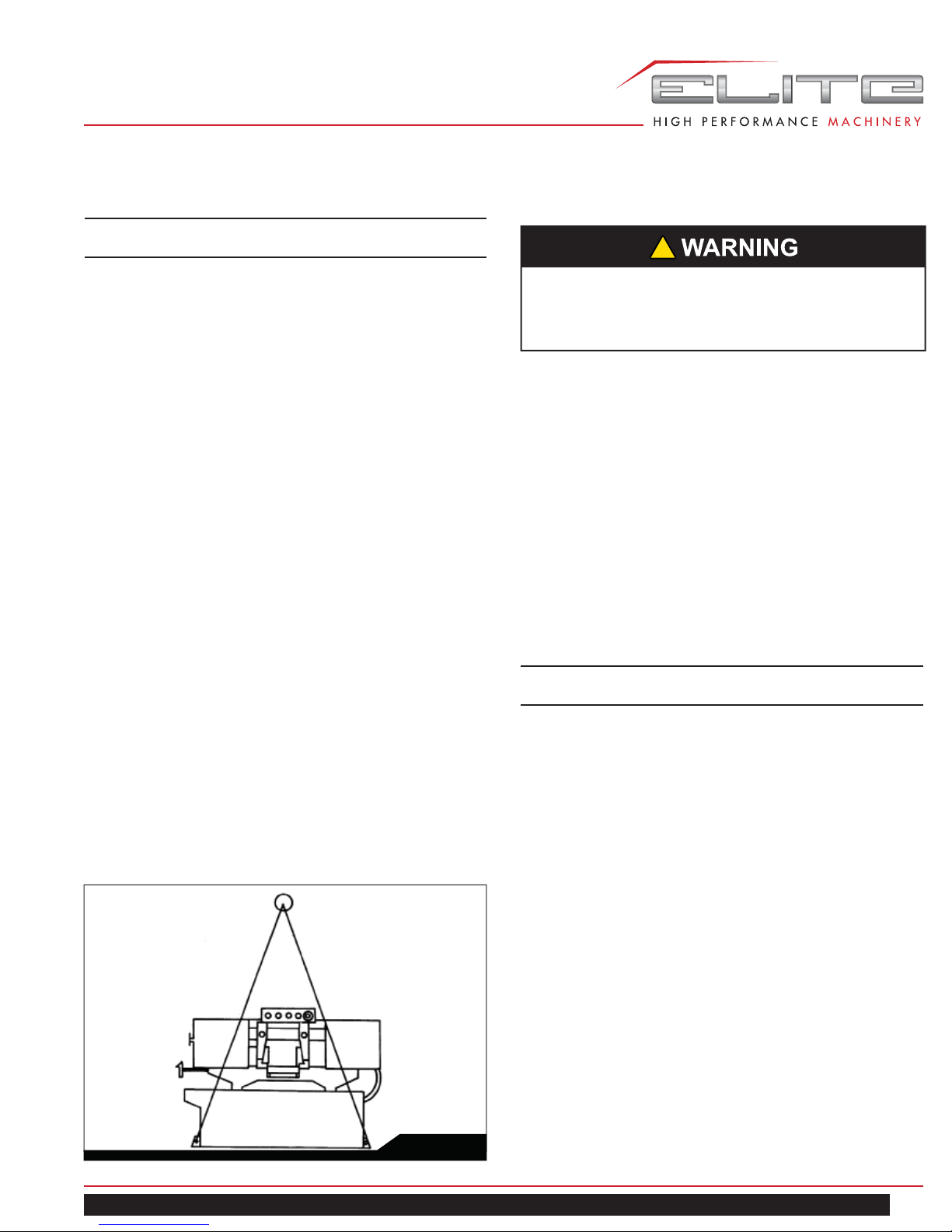
1. Using lifting straps that are isolated from the band
saw’s fi nished surfaces, lift machine and place in
desired location. See Figure 1 for strap placement.
2. Install four leveling bolts with lock nuts on both sides
of the base as shown in the parts breakdown on page
16, items 2 and 3.
3. Place a level on the table surface and check side-to-
side and front-to-back.
4. Adjust leveling screws until machine is level in both
directions and tighten locking nuts.
8.0 ELECTRICAL CONNECTIONS
!
All electrical connections must be done by a
qualifi ed electrician. All adjustments or repairs must
be done with machine disconnected from power
source. Failure to comply may cause serious injury.
The EHB-916V Band Saw is rated at 115/230V single
phase, and is pre-wired 115 volt from the factory. The
EHB-1018V is rated at 230V only, single phase. Confi rm
that power available at the saw’s location matches that for
which the saw is wired.
To convert the EHB-916V from 115V to 230V, the following
items will have to be changed:
Main Motor – follow diagram inside junction box cover.
Coolant Pump – Remove chip pan on front of saw,
remove junction box cover on pump, and follow diagram
inside junction box cover.
Control Transformer – Open electrical panel on rear of
base and change the fuse from 115V to 230V.
Machine must always be correctly grounded.
NOTE: The power cord end will have to be changed to
one rated 230V when changing to the higher voltage.
EHB-916V | EHB-1018V
Fig. 1
7
Page 8
9.0 CONTROLS
11.0 PRIOR TO OPERATION
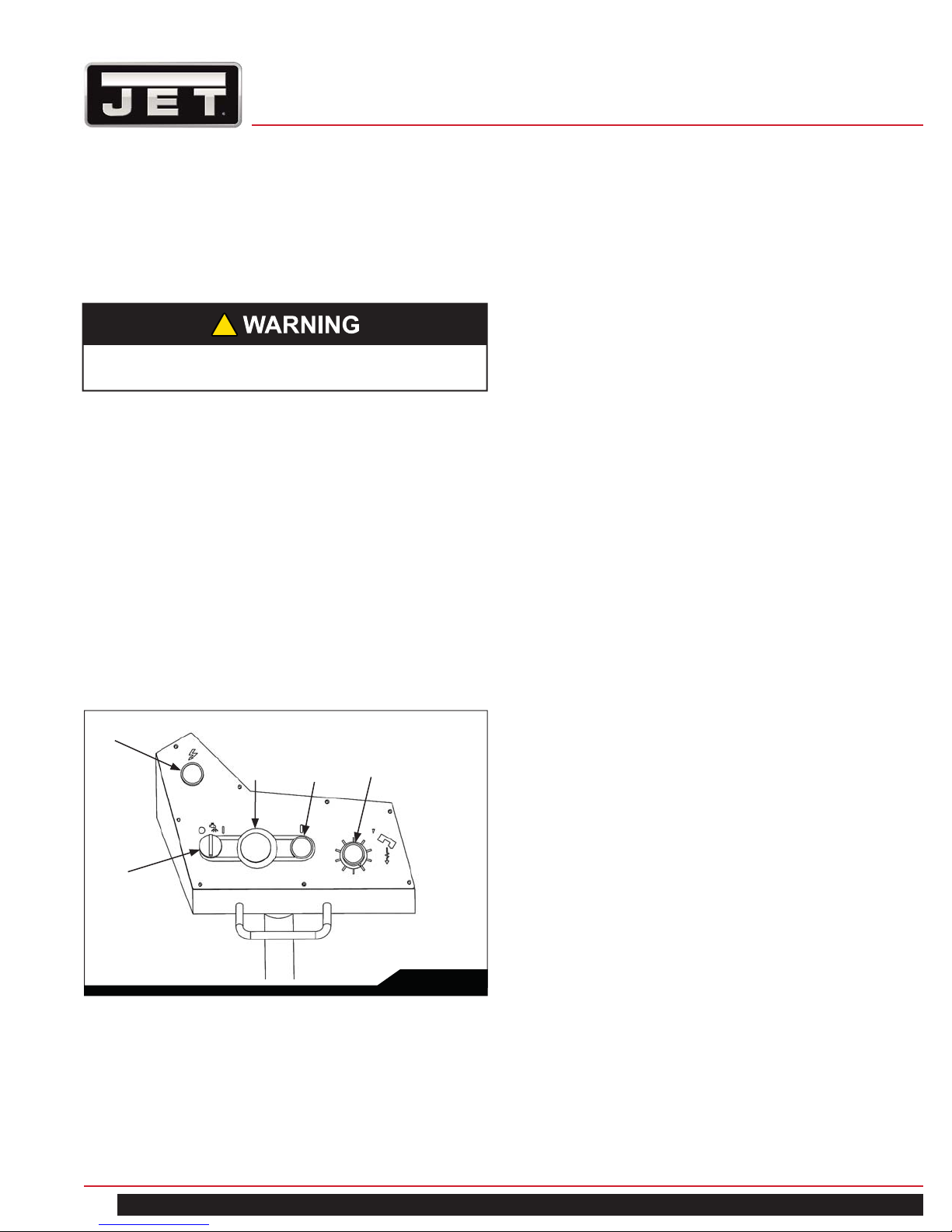
Refer to Figure 2.
Power Indicator Light (A) – lit whenever machine is
running.
!
If the bulb is out, lamp will not light, but machine
may still have power.
Start Button (B) – press to start band saw.
Emergency Stop Button (C) – press to immediately stop
all machine functions.
Coolant Switch (D) – Turn arrow to “I” to turn on coolant
fl ow. Turn arrow to “O” to stop coolant fl ow.
Feed Rate Control (E) – this knob is used to set the
amount of downward force that is applied to the saw
blade. The feed rate is proportional to the opening of the
valve. When set to zero, the saw head is locked in the
raised position. Increasing the valve opening (counterclockwise adjustment) increases the feed rate; decreasing
the valve opening (clockwise adjustment) reduces the
feed rate.
1. Check that blade tooth direction matches diagram on
blade guides.
2. Check to see that blade is properly seated on wheels
after applying correct tension (approximately 25,000
lbs.).
3. Set blade holder guides for approximately .003” to
.005” clearance between guides and blade.
4. Check for slight clearance between back up rollers
and back of blade.
5. Position blade guides as close to workpiece as pos-
sible.
6. Select proper speed and feed rate for material being
cut.
7. Material to be cut must be securely held in vise.
8. Check to see that coolant level is adequate and turn
on coolant pump if material to be cut requires it.
Machine should be fi lled with four gallons of the
proper coolant mixture. Follow the directions on the
product maker’s label and fi ll the coolant tank
through the chip tray area.
9. Do not start cut on a sharp edge.
10. Keep machine lubricated. See “Lubrication” section.
A
C
D
B
E
Fig. 2
10.0 AUXILIARY COOLANT HOSE
Your saw is equipped with an auxiliary coolant hose. This
can be used when a large amount of coolant needs to be
directed at the work piece.
12.0 OPERATING CONTROLS AND
ADJUSTMENTS
12.1 REMOVING AND INSTALLING THE BLADE
When your machine was shipped, a blade was supplied
and assembled to the saw.
1. Disconnect the machine from the power source.
2. Raise the saw frame about 6” and close the feed rate
lever by turning it clockwise as far as it will go.
3. Open both wheel covers and clean the swarf out of
the machine.
4. Release blade tension by turning the blade tension
handwheel (C) Fig. 3 counterclockwise.
5. Remove the blade from both wheels and out of each
blade guide.
6. Make sure the teeth of the new blade are pointing in
the direction of travel. If necessary, turn the
blade inside out.
8
Horizontal Band Saw
Page 9
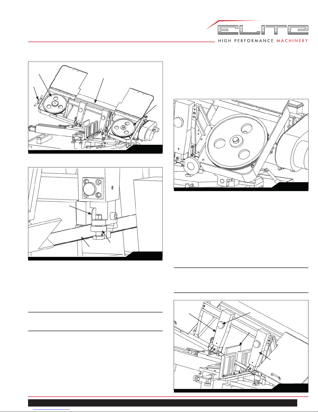
11. Jog the power “on” and “off” to be sure the blade is in
A
B
C
place and tracking properly.
If blade is not tracking properly refer to the section
12.11 “Adjust Blade Tension and Blade Tracking
Adjustment”.
A
Fig. 3
Fig. 5
E
F
D
Fig. 4
7. Place the blade in place on the wheels (A) and
through the upper blade guard (B) Fig. 3 is shown
with the wheel covers removed for clarity.
8. Work the blade (F) all the way up into the blade guide
roller bearings (D) with the back of the blade against
the back-up bearing (E), as shown in Fig. 4.
NOTE: If roller bearings need adjusting refer to
the section ADJUSTING BLADE GUIDE ROLLER
BEARINGS.
9. Put light tension on the blade and work it on both
wheels, as shown in Fig. 5.
12.2 ADJUSTING BLADE GUIDE BRACKETS
The blade guides should be set as close to the vise jaw as
possible. The right blade guide bracket (A) Fig. 6, is not
adjustable and is set at the factory to clear the right hand
vise jaw. The left blade guide bracket (B) can be moved
to the left or right depending on the position of the left
hand vise jaw (C).
To move the left blade guide bracket (B), loosen hand
knob (D), position blade guide bracket (B) and tighten
hand knob (D).
Note: when operating 916/SA, the right blade guide
bracket (A) can be moved as well, especially when
cutting in 90° to make sure the bracket be moved as
close to the vise jaw as possible.
B
D
C
MAKE SURE THAT THE BACK OF THE BLADE
IS AGAINST THE WHEEL FLANGES OF
BOTH WHEELS. THIS IS VERY IMPORTANT.
10. When you are sure the back of the blade is against
the wheel fl anges of both wheels and properly insert-
ed into the guides, fi nish putting tension on the blade.
EHB-916V | EHB-1018V
A
Fig. 6
9
Page 10
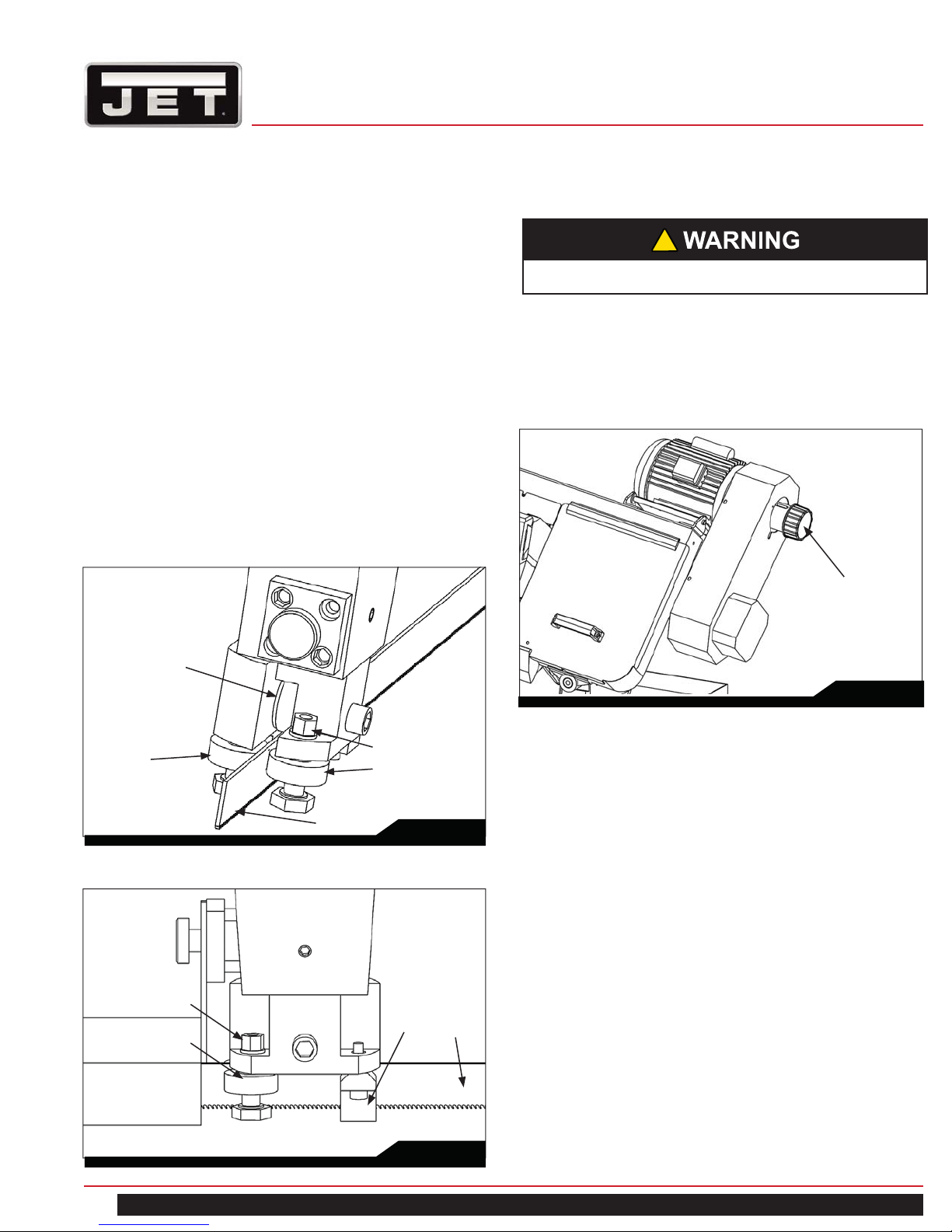
12.3 ADJUSTING BLADE GUIDE ROLLER
BEARINGS
12.4 CHANGING BLADE SPEED
The back of the blade (A) Fig. 7, should ride against the
back-up support bearing (B) which is positioned at an
angle so as to provide greater bearing support, eliminating
bearing wear and extending blade life.
The saw blade (A) should also ride between the two roller
bearings (C) and (D) Fig. 7.
The rear bearing (C) on the left hand blade guide can
be easily adjusted to suit blade thickness by loosening
nut (E). The bearing (C) is on an eccentric shaft which
enables it to be adjusted for blade thickness in the same
manner with the exception that the adjustable roller
bearing is in the forward position.
Part (F) shown Fig. 8 is a tungsten carbide block, after
completing the adjustments shown in Fig. 7, tighten the
Part (F) onto the surface of the saw blade.
B
!
Only adjust speed with power on and blade turning.
1. Raise cutting head approximately six inches above
work piece and turn feed rate knob to zero.
2. Turn power on and turn speed adjuster knob (as in
Figure 9) to match appropriate material.
Speed Adjuster Knob
Fig. 9
D
E
C
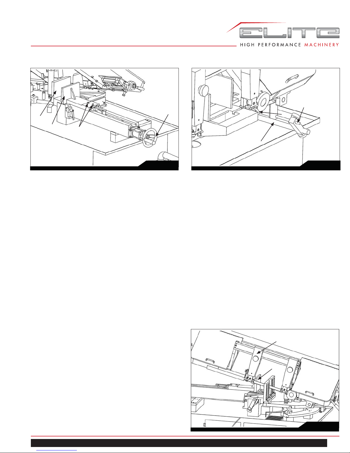
12.5 OPERATING VISE
The workpiece is placed between the vise jaws with the
required amount to be cut-off extending out past the blade.
A
Fig. 7
To position the moveable vise jaw (B) instantly, simply turn
vise handknob (A) Fig. 10, counterclockwise 1/2 turn and
move the vise jaw (B) to the desired position.
Then tighten vise by turning the knob (A) clockwise.
The vise can be adjusted to cut any angle from 0° to 45°
by loosening the two bolts (C) Fig, 10, on each vise jaw.
Position the vise jaws to the desired angle and tighten the
bolts. It is also necessary, when angle cutting, to move
the right hand vise jaw (D) to the left until the workpiece
E
F
C
A
and right hand vise jaw clears the right hand guide arm.
Fig. 8
10
Horizontal Band Saw
Page 11
A
D
B
C
A
C
B
Fig. 10
12.6 BOW WEIGHT ADJUSTMENT
Bow weight is one of the most important adjustments of
the saw. If the bow weight is not set properly, one can
expect poor performance, crooked cuts, tooth stripping,
stalling, and the blade popping off the blade wheels. The
hydraulic feed rate unit will not compensate for improper
bow weight. Bow weight has been set at the factory and
should not need any adjustment. If adjustment becomes
necessary:
1. Disconnect machine from power source.
2. Turn feed rate control (E, Figure 2)
counterclockwise until it stops.
3. Place one end of a fi sh-type scale under the blade
tension handle and lift the saw with the other end.
The scale should indicate approximately 18-20 lbs.
for the HBS-916W. For the HBS-1018W, it should
indicate 22-24 lbs.
4. Adjust tension to approximately 18-20 lbs. (or 22-24
lbs.) by turning the adjustable C-bolt found at the end
of the coil spring on the rear of the band saw.
5. Connect the machine to the power source.
Fig. 11
12.8 SETTING UP THE MACHINE FOR
OPERATION
1. Select the proper speed and blade for the type of
material you are cutting.
2. Make sure blade tension is adjusted properly.
3. Lift the saw frame up and close the feed rate lever.
4. Place the stock between the vise jaws, set the stock
for the desired width of cut and tighten the vise.
5. Make sure the left blade guide bracket (A) is adjusted
as close as possible to the left vise jaw (B) Fig. 12.
6. Turn the machine on and if your machine is equipped
with a coolant system, adjust coolant fl ow by turning
lever (D) Fig. 2.
7. Turn the feed rate control (E) Fig 2, counterclock
wise until the saw blade begins to lower the desired
rate of speed.
8. Proceed to cut throughout the workpiece, as shown in
Fig. 12. Shut the machine off upon completion of cut.
A
12.7 ADJUSTING STOCK ADVANCE STOP
The Stock Advance Stop is used mainly when more than
one piece is to be cut to the same length. Simply position
the stop block (A) Fig.11, the desired distance away from
the blade.
The stop may be repositioned by loosening screw (B) and
moving the rod (C) accordingly. To move the stop block
(A) out of the way simply push it to the down position.
EHB-916V | EHB-1018V
B
Fig. 12
11
Page 12

12.9 AUTOMATIC SHUT-OFF
The machine and any accessories which are wired into
the electrical system are controlled by the start-stop
buttons. The machine will automatically shut off when the
cut is completed. The lever (A) Fig. 13, for the automatic
shut-off contacts the top of the hydraulic cylinder (B) and
shuts off the machine.
LUBRICATION OF HYDRAULIC SYSTEM
If it is necessary to fi ll the hydraulic cylinder with oil,
proceed as follows:
1. Lift the saw frame slightly (about 15°), place a block
underneath the saw frame to hold it.
2. Turn cover (B) shown in Fig. 13 counterclockwise,
then fi ll hydraulic oil or equivalent until it is full.
A
B
Fig. 13
A
Fig. 14
12.11 ADJUST BLADE TENSION & BLADE
TRACKING ADJUSTMENT
Blade tension has been preset in factory; therefore, by
turning handwheel (A) in Fig. 15 clockwise until (B) portion
slip then tension for the blade is reached. Please note
that one does not need to press the handwheel, simply
turn. For blade tracking, if the back of the blade is not
against the wheel fl ange properly, loosen the screw (C) in
Fig. 15, and adjust screw (D) in Fig. 15, until the blade is
tracking properly, then tighten screw (C).
C
D
A
12.10 GEAR CASE
After the fi rst 50 hours of use the gear case should be
drained and refi lled. Remove drain plug (A) Fig. 14 drain
all of the oil out of the gearbox. Remove oil fi ller plug
located underneath the right wheel and fi ll the gear case
with 850ml of multi-function gearbox oil or equivalent.
12
B
Fig. 15
Horizontal Band Saw
Page 13

13.0 MAINTENANCE
15.0 REPLACEMENT PARTS —
EHB-916V and EHB-1018V
!
Before doing maintenance on the machine, disconnect it from the electrical supply by pulling out the
plug or switching off the main switch! Failure to
comply may cause serious injury.
Keep the band saw and the motor clean.
If the power cord is worn, cut, or damaged in any way,
have it replaced immediately.
14.0 LUBRICATION
All ball bearings are permanently lubricated and sealed.
They require no further attention.
The gear box lubricant should be changed after the fi rst 50
hours of operation. Change lubricant from then on every
250 hours of operation.
To check level of gear box lubricant, place saw arm in
down position and allow a few minutes to pass so that oil
drains down. Check level in sight glass on side of gear
casing. Correct level is the dot in the middle of sight glass.
To change gear box lubricant:
1. Disconnect the machine from the power source.
2. Open drain plug and allow lubricant to drain
completely. Drain plug may be found on lower front of
gear case under right wheel cover. Remove drain plug
with a hex wrench.
3. Replace drain plug.
4. Remove fi ller cap and fi ll gear box with Mobil DTE®
Oil Heavy Medium until level reaches dot in middle of
sight glass.
5. Replace fi ller cap.
6. Connect machine to the power source.
Replacement parts are listed on the following pages.
To order parts or reach our service department, call
1-855-336-4032, Monday through Friday (see our
website for business hours, www.jettools.com). Having
the Model Number and Serial Number of your machine
available when you call will allow us to serve you quickly
and accurately.
®
JET
427 New Sanford Road
LaVergne, Tennessee 37086
www.jettools.com
Phone: 855-336-4032
Use a light machine oil to lubricate all other moving parts
as needed.
EHB-916V | EHB-1018V
13
Page 14

SAW STAND AND BED ASSEMBLY — EHB-916V
79-2
79
55
56-1
90-1
83
82
54-1
85
1
2
3
62
65
56
84
89
88
87
86
4
90
59
60
61
63
66
64
79-1
79-3
8
6
7
19
9
10
57-1
15
14
13
11
58
57
18
12
54
72-1
16
67
79-5
79-4
20
21
24
26
17
33
34
74
25
28
29
30
27
31
35
32
37
36
69
70
71
73
81
80
77
23
22
45
41
44
47
43
46
48
68
72
78-2
78-1
5
76
50
75
72-2
40
39
38
42
49
52
53
51
78
14
Horizontal Band Saw
Page 15

PARTS LIST SAW STAND AND BED — EHB-916V
Index No. Part No. Description Size Qty.
1 EHB916V-64 Fitting 1
2 EHB916V-65 Tubing 5/16" × 65". 2
3 EHB916V-66 Valve . 1
4 EHB916V-67 Feed Knob . 1
5 EHB916V-101 Cable Glands PG-11 5
6 TS-0209071 Socket Head Cap Screw 3/8 × 1-1/2" 2
7 EHB916V-191 Special Washer 2
8 EHB916V-192 Vise Jaw Bracket 1
9 EHB916V-193 Roll Pin 3/16 × 1-1/8" 1
10 EHB916V-194 Bracket 1
11 EHB916V-195 Acme Nut Assembly 1
12 EHB916V-196 Button 1
13 EHB916V-197 Retainer 1
14 TS-0680011 Flat Washer 3/16" 2
15 EHB916V-199 Round Head Screw 3/16” x 3/8” 1
16 EHB916V-200 Block 1
17 EHB916V-201 Vise Jaw Bracket (fi xed) 1
18 EHB916V-191 Special Washer 2
19 TS-0209061 Socket Head Cap Screw 3/8 ×1-1/4" 2
20 TS-0070031 Hex Cap Screw 1/2-13 ×1-1/2" 1
21 TS-0561031 Hex Nut 3/8" 1
22 EHB916V-206 Limit Switch 1
23 EHB916V-207 Limit Switch Seat(Ser No.13100009 and lower) 1
EHB916V-207N Limit Switch Seat(Ser No.xxxx0010 and high-
er)
EHB916V-OHCA Oil Hydraulic Cylinder Assembly (includes
#24-34)
24 EHB916V-210 Cap 1
25 EHB916V-211 Oil Seal 1
26 EHB916V-213 Rod 1
27 TS-0680031 Flat Washer 5/16" 1
28 EHB916V-215 Piston 1
29 EHB916V-216 Seal 1
30 EHB916V-217 Inoin ring 1
31 TS-0561021 Hex Nut 5/16" x 18T 2
32 EHB916V -219 Tube Assembly 1
33 EHB916V-221 Tube fi tting 1
34 EHB916V-222 Tube fi tting 1
35 EHB916V-223 Retaining ring 1
36 EHB916V-224 Pivot shaft 1
37 EHB916V-225 Socket Set Screw 3/8"-16T × 3/8" 1
38 TS-0680031 Flat Washer 5/16" 4
39 TS-0051051 Hex Cap Screw 5/16 × 1" 4
40 EHB916V-232 Motor Plate 1
41 EHB916V-233 Rear Pivot Bracket 1
42 EHB916V-234 Special Socket Set Screw 2
43 EHB916V-235 Hex Nut 1/2"-12 2
1
1
EHB-916V | EHB-1018V
15
Page 16

Index No. Part No. Description Size Qty.
44 TS-0209081 Socket Head Cap Screw 3/8"-16T × 1-3/4" 3
45 TS-0680041 Flat Washer 3/8" 3
46 TS-0050031 Hex Cap Screw 1/4-20T × 3/4" 1
47 TS-0680021 Flat Washer 1/4" 1
48 TS-0271051 Set Screw 3/8"-16 × 1/2" 1
49 EHB916V-241 Strap 1
50 TS-0680021 Flat Washer 1/4" 2
51 EHB916V-243 Hex Cap Screw 1/4-20T ×3/4" 2
52 EHB916V-26 Special Washer 1
53 EHB916V-245 Knob 1
54 EHB916V-247 Bed 1
54-1 EHB916V-247-1 Seat 1
55 EHB916V-248 Pin 1
56 EHB916V-249 Hand Wheel 1
56-1 EHB916V-249-1 Handle 1
57 EHB916V-252 Acme Screw 1
57-1 EHB916V-252-1 Collar 1
58 EHB916V-253 Roll Pin 6 ø ×30 ø 1
59 EHB1018V-254 Work Support 1
60 TS-0680041 Flat Washer 3/8" 2
61 TS-0060061 Hex Cap Screw 3/8" ×1-1/4" 2
EHB1018V-SA Adj. Stock Stop Assembly (includes #62-66) 1
62 TS-0060061 Hex Cap Screw 3/8" ×1-1/4" 1
63 EHB1018V-258 Shaft 7/8” 1
64 EHB1018V-259 Stop Bracket 1
65 EHB1018V-260 Bar 1
66 EHB916V-261 Knob 2
67 EHB916V-265 Collar 2
68 TS-0271031 Set Screw 3/8-16T ×3/8" 4
69 EHB916V-267 Copper 2
70 TS-0271031 Socket Set Screw 3/8-16T ×3/8" 2
71 EHB916V-269 Pivot Shaft 1
72 EHB916V -272 Base Assembly 1
72-1 EHB916V-272-1 Door 1
72-2 EHB916V-272-2 Door 1
73 TS-0060031 Hex Cap Screw 3/8" x 3/4" 2
74 TS-0680041 Flat Washer 3/8" 2
75 EHB916V-275 Knob 1
76 EHB916V-276 Adjustable Bolt 1
77 EHB916V-277 Spring 1
78 EHB916V-278 Gun Set 1
78-1 EHB916V-278-1 Hook 1
78-2 EHB916V-278-2 Hex Cap Screw 2
79 EHB916V-281 Coolant T ank 1
79-1 EHB916V-281-1 Coolant Pump 1
79-2 EHB916V-281-2 Pan Head Machine Screw 4
79-3 EHB916V-96 3 Way Coolant Block 1
16
Horizontal Band Saw
Page 17

Index No. Part No. Description Size Qty.
79-4 EHB916V-281-4 Lock w/ key 1
79-5 EHB916V-281-5 Lock w/o key 1
80 EHB916V-283 Hex Nut 1/2"-12T 4
81 EHB916V-284 Hex Cap Screw 1/2" -12T x 2" 4
82 TS-0720081 Lock Washer 5/16" 3
83 TS-0051051 Hex Head Screw 5/16"-18 ×1" 3
84 EHB916V-289 Socket Head Button Screw 3/16" x 3/8" 8
85 EHB916V-300 Nameplate 1
86 EHB916V-301 Start Switch 1
87 EHB916V-302 Emergency Switch 1
88 EHB916V-303 Selection Switch 1
89 EHB916V-305 Indication Light For Power 1
90 EHB916V-306 Control Box 1
90-1 EHB916V-306-1 Tube 1
EHB-916V | EHB-1018V
17
Page 18

SAW ARM ASSEMBLY — EHB-916V
90
2
46
44
43
90-1
22
41
35-1
50
1-1
47
9
24
1
23
40
111
110
113
128
100
169
131
153
89
157
103
134-1
130
124
125
84
134
83
129
114
126
155
122
127
97
112
132
98
145
156
133
99
146
147
142 138
144
136
146
141
148
139
146
146
135
149
154
167
168
156-2
156-1
149
146
154-2
137
140
151
150
154-1
58
57
56
55
52
95
39
38
35
51
36
34
37
6
5
11
10
3
14
18
19
49
16
14
21
20
48
15
4
8-1
17
165
12
13
166
31
33
7
73
68-1
32
8
74
42
70
88
45
93
92
82
91
87
96
71
75
121
68
160
161
29
28
29
26
86-1
159
76
25
94
86
86-2
77
79
109
118
119
85
78
80
81
158
123
18
Horizontal Band Saw
Page 19

PARTS LIST SAW ARM — EHB-916V
Index No. Part No. Description Size Qty.
1 EHB916V-01 Handwheel 1
1-1 EHB916V-01-1 Handwheel handle 2
2 EHB916V-02 Collar 1
3 EHB916V-03 Shaft 1
4 EHB916V-04 Bracket 1
5 EHB916V-05 Slide 1
6 EHB916V-06 Gib 2
7 EHB916V-07 Collar 1
8 EHB916V-08 Roll pin M5x30 2
8-1 EHB916V-08-1 Roll pin M5x40 1
9 TS-0081031 Hex Cap Screw 5/16 x 3/4 4
10 EHB916V-10 Adjusting Screw 3/4 x 1-1/2 1
11 TS-0060111 Hex Cap Screw 3/8 x 2-1/2 1
12 TS-0271031 Set Screw 3/8" x 3/8 1
13 EHB916V-13 Spindle 1
14 BB-51103 Thrust bearing 51103 2
15 TS-0060061 Hex Cap Screw 3/8 x 1-1/4 1
16 EHB916V-16 Roll pin 5 × 30L 1
17 TS-0732061 Lock Washer 3/8" 1
18 EHB916V-18 Driven 1
19 EHB916V-19 Thrust Bearing Housing 1
20 EHB916V-20 Lock Nut 1
21 EHB916V-21 Disc Spring 6
22 EHB916V-22 Copper 1
23 TS-0267041 Set Screw 1/4 x 3/8 1
24 TS-0720081 Lock Washer 5/16" 1
25 TS-0060051 Hex Cap Screw 3/8" x 1" 1
26 EHB916V-26 Special Washer 1
28 EHB916V-28 Wheel L.H 1
29 BB6306ZZ Bearing 6306ZZ 2
31 EHB916V-31 Output Shaft 1
32 EHB916V-32 Oil Seal 32.42.7. 1
33 BB-30207 Bearing 1
34 EHB916V-34 Oil Plug 1/8" 1
35 EHB916V-35 Gear Box housing 1
35-1 EHB916V-35-1 Cover 1
EHB916V-GBCA Gear Box Cover Assembly(
included 35, 35-1)
36 TS-0060081 Hex Cap Screw 3/8-16 × 3/4" 3
37 TS-0732061 Lock Washer 3/8" 3
38 EHB916V-38 Worm Gear 1
39 EHB916V-39 Key 7 x 7 x 35 1
40 BB-30206 Bearing 1
41 TS-0267121 Set Screw 1/4" × 3/4" 3
42 EHB916V-42 Cap 1
43 TS-0732061 Lock Washer 3/8" 3
44 TS-0060071 Hex Cap Screw 3/8"-16 × 1-1/2" 3
1
EHB-916V | EHB-1018V
19
Page 20

Index No. Part No. Description Size Qty.
45 TS-0207021 Socket Head Cap Screw 1/4"-20 × 5/8" 3
46 TS-0561011 Hex Nut 1/4” 3
47 EHB916V-47 Cap 1
48 SB-3/16 Steel Ball 2
49 TS-0270061 Set Screw 5/16"-18 × 5/8" 1
50 TS-0207021 Socket Head Cap Screw 1/4"-20 × 5/8" 4
51 BB-6004 Bearing 6004 1
52 EHB916V-52 Input Shaft 1
55 BB-3205 Bearing 3205 1
56 EHB916V-56 Oil Seal 25.35.7 1
57 EHB916V-57 Cap 1
58 TS-0207021 Socket Head Cap Screw 1/4"-20 × 5/8" 4
68 EHB916V-68 Bow Frame 1
68-1 EHB916V-68-1 Frame Handle 1
70 TS-0081031 Hex Cap Screw 5/16" x 3/4" 2
71 TS-0680031 Flat Washer 5/16" 2
73 EHB916V-73 Tube Retainer 2
74 EHB916V-74 Round Head Screw 3/16" x 3/8" 2
75 EHB916V-75 Bracket (Left Side) 1
76 TS-0680031 Flat Washer 5/16" 2
77 TS-0081031 Hex Cap Screw 5/16" x 3/4" 2
78 TS-0081031 Hex Cap Screw 5/16" x 3/4" 2
79 TS-0680031 Flat Washer 5/16" 2
80 EHB916V-80 Drive Wheel. 1
81 TS-0271032 Socket Set Screw 3/8-24 ×3/8" 1
82 EHB916V-82 Key 7 ×7 ×40 1
83 TS-0081031 Hex Cap Screw 5/16-18 ×3/4" 2
84 TS-0720081 Lock Washer 5/16" 2
85 EHB916V-85 Bracket 1
86 EHB916V-86 Sensor 1
86-1 EHB916V-86-1 Sensor seat 1
86-2 EHB916V-86-2 Screw 2
87 EHB916V-75 Bracket 1
88 EHB916V-88 Knob 2
89 EHB916V-88 Knob 1
90 EHB916V-90 Blade T ension Gauge 1
EHB916V-90A Blade Tension Gauge As-
1
sembly (includes #20,90)
90-1 EHB916V-90-1 Pin 1
91 EHB916V-91 Front Pivot Bracket 1
92 TS-0732061 Lock Washer 3/8" 3
93 TS-0060081 Hex Cap Screw 3/8-16 ×3/4" 3
94 TS-0271051 Socket Set Screw 3/8-16 ×1/2" 1
95 EHB916V-95 Motor 1-1/2Hp,115/230V 1
96 EHB916V-96 3 Way Coolant Block 1
97 EHB916V-97 Hose 2
98 EHB916V-98 Valve 2
99 EHB916V-99 Hose Clamp 2
20
Horizontal Band Saw
Page 21

Index No. Part No. Description Size Qty.
100 EHB916V-100 Belt 1
103 EHB916V-103 Upper Guard 1
109 EHB916V-109 Lower Guard 1
110 EHB916V-110 Motor Pulley 1
111 TS-0270021 Socket Set Screw 5/16-18 ×5/16" 1
112 EHB916V-112 Pulley 1
113 TS-0270021 Socket Set Screw 5/16-18 ×5/16" 1
114 EHB916V-114 Key 5 x 5 x 40 1
118 TS-0720081 Lock Washer 5/16" 2
119 EHB916V-119 Hex Head Screw 5/16”-20 ×3/4" 2
121 EHB916V-121 Round Head Screw #10-3/16 ×3/8" 4
122 EHB916V-122 Cover R.H 1
123 TS-0255041 Socket Head Button Screw 5/16” x 18 x 3/4” 4
124 TS-0060051 Hex Cap Screw 3/8” x 16 x 1 1
125 TS-0561031 Hex Nut 3/8” x 16 1
126 TS-0680041 Lock Washer 3/8" 3
127 TS-0060081 Hex Cap Screw 3/8 ×16 ×3/4" 3
128 EHB916V-128 Stationary plate 2
129 EHB916V-129 Bracket 1
130 TS-0209071 Socket Head Cap Screw 3/8"-16 ×1-1/2" 2
131 TS-0267071 Set Screw 1/4"-20 ×3/4" 4
132 TS-0270061 Set Screw 5/16"-18 ×5/8" 1
133 EHB916V-133 Bracket-R.H. 1
134 EHB916V-134 Slide 1
134-1 EHB916V-134-1 Scale 1
135 EHB916V-135 Screw 3/16"-24 × 7/8" 4
136 EHB916V-136 Carbide Guide 4
137 EHB916V-137 Collar 2
138 TS-0267021 Set Screw 1/4"×1/4" 2
139 EHB916V-139 Wire Brush 1
140 EHB916V-140 Brush Support 1
141 TS-0207021 Socket Head Cap Screw 1/4"-20 × 5/8" 2
142 TS-0680021 Flat Washer 1/4" x 19 x 2.0 2
144 EHB916V-144 Guide 2
145 TS-0561021 Hex Nut 5/16"-18T 2
146 TS-0680041 Flat Washer 3/8" 4
147 BB6200ZZ Bearing 6200 ZZ 1
148 EHB916V-148 Special Screw M10 x 30 1
149 BB6200ZZ Bearing 6200 ZZ 2
150 EHB916V-150 Special Screw 1
151 EHB916V-151 Special Screw 1
153 EHB916V-153 Adjustable Handle 1
154 EHB916V-154 Guide Cover 1
154-1 EHB916V-154-1 Screw 2
154-2 TS-0680011 Washer 2
155 EHB916V-155 Bracket-L.H. 1
EHB-916V | EHB-1018V
21
Page 22

Index No. Part No. Description Size Qty.
156 EHB916V-156 Blade Cover 1
156-1 EHB916V-156-1 Screw 2
156-2 TS-0680011 Washer 2
157 EHB916V-157 Blade Cover 1
158 EHB916V-158 Special Knob 1
159 TS-0680041 Flat Washer 3/8" 3
160 EHB916V-160 Hex Head Screw 3/8 ×16 ×3/4" 3
161 EHB916V-161 Bracket 1
165 EHB916V-165 Round Head Screw 3/16 ×3/8" 4
166 EHB916V-166 Cover L.H 1
167 EHB916V-167 Handle 2
168 TS-081F051 Phillips Screw 1/4"-20 × 3/4" 4
169 891095 Blade 1"x 0.035" x 128-1/2" (4/6T) 1
22
Horizontal Band Saw
Page 23

SAW STAND AND BED ASSEMBLY — EHB-1018V
79-2
79
56-1
55
84
56
85
90
89
88
87
4
91
91-1
59
60
61
66
63
83
82
57
86
1
62
65
58
3
57-1
54
2
79-1
79-3
6
7
8
9
10
15
14
13
11
19
18
12
72-1
33
34
67
79-5
79-4
20
71
78-1
5
76
68
41
78-2
23
22
45
44
47
43
46
50
48
75
21
24
17
16
74
26
25
28
29
30
27
31
35
32
37
36
69
70
72
73
81
80
77
72-2
40
39
42
49
52
51
78
38
53
64
EHB-916V | EHB-1018V
23
Page 24

SAW STAND AND BED — EHB-1018V
Index No. Part No. Description Size Qty.
1 EHB916V-64 Fitting 1
2 EHB916V-65 Tubing 5/16" × 65". 2
3 EHB916V-66 Valve 1
4 EHB916V-67 Feed Knob 1
5 EHB916V-101 Cable Glands PG-11 5
6 TS-0209071 Socket Head Cap Screw 3/8 × 1-1/2" 2
7 EHB916V-191 Special Washer 2
8 EHB1018V-192 Vise Jaw Bracket 1
9 EHB916V-193 Roll Pin M5 x 20 1
10 EHB916V-194 Bracket 1
11 EHB916V-195 Acme Nut Assembly 1
12 EHB916V-196 Button 1
13 EHB916V-197 Retainer 1
14 TS-0680011 Flat Washer 3/16" 2
15 EHB916V-199 Round Head Screw 3/16" x 3/8" 1
16 EHB1018V-200 Block 1
17 EHB1018V-201 Vise Jaw Bracket (fi xed) 1
18 EHB916V-191 Special Washer 2
19 TS-0209061 Socket Head Cap Screw 3/8 ×1-1/4" 2
20 TS-0070031 Hex Cap Screw 1/2-13 ×1-1/2" 1
21 TS-0561031 Hex Nut 3/8" 1
22 EHB916V-206 Limit Switch 1
23 EHB916V-207 Limit Switch Seat(Ser
No.13100009 and lower)
EHB916V-207N Limit Switch Seat (Ser
No.xxxx0010 and higher)
EHB916V- OHCA Oil Hydraulic Cylinder As-
sembly (includes # 24-34)
24 EHB916V-210 Cap 1
25 EHB916V-211 Oil Seal 20.35.7 1
26 EHB916V-213 Rod 1
27 TS-0680031 Flat Washer 5/16" 1
28 EHB916V-215 Piston 1
29 EHB916V-216 Seal 1
30 EHB916V-217 Inoin ring P53 1
31 TS-0561021 Hex Nut 5/16" x 18T 2
32 EHB916V -219 Tube Assembly 1
33 EHB916V-221 Tube Fitting 1
34 EHB916V-222 Tube Fitting 1
35 EHB916V-223 Retaining Ring S-17 1
36 EHB916V-224 Pivot shaft 1
37 EHB916V-225 Socket Set Screw 3/8"-16T × 3/8" 1
38 TS-0680031 Flat Washer 5/16" 4
39 TS-0051051 Hex Cap Screw 5/16 × 1" 4
40 EHB916V-232 Motor Plate 1
41 EHB1018V-233 Rear Pivot Bracket 1
42 EHB916V-234 Special Socket Set Screw 1/2" x 2" 2
1
1
1
24
Horizontal Band Saw
Page 25

Index No. Part No. Description Size Qty.
43 EHB916V-235 Hex Nut 1/2"-12 2
44 TS-0209081 Socket Head Cap Screw 3/8"-16T × 1-3/4" 3
45 TS-0680041 Flat Washer 3/8" 3
46 TS-0050031 Hex Cap Screw 1/4-20T × 3/4" 1
47 TS-0680021 Flat Washer 1/4" 1
48 TS-0271051 Set Screw 3/8"-16 × 1/2" 1
49 EHB916V-241 Strap 1
50 TS-0680021 Flat Washer 1/4" 2
51 EHB916V-243 Hex Cap Screw 1/4-20T ×3/4" 2
52 EHB916V-26 Special Washer 1
53 EHB916V-245 Knob 1
54 EHB1018V-247 Bed 1
55 EHB916V-248 Pin 1
56 EHB916V-249 Hand Wheel 1
56-1 EHB916V-249-1 Handle 1
57 EHB1018V-252 Acme Screw 1
57-1 EHB916V-252-1 Collar 1
58 EHB916V-253 Roll Pin 6 ø ×30 ø 1
59 EHB1018V-254 Work Support 1
60 TS-0680041 Flat Washer 3/8" 2
61 TS-0060061 Hex Cap Screw 3/8" ×1-1/4" 2
EHB1018V-SA Adj. Stock Stop Assembly
1
(includes #62-66)
62 TS-0060061 Hex Cap Screw 3/8" ×1-1/4" 1
63 EHB1018V-258 Shaft 1
64 EHB1018V-259 Stop Bracket 1
65 EHB1018V-260 Bar 1
66 EHB916V-261 Knob 2
67 EHB916V-265 Collar 2
68 TS-0271031 Socket Set Screw 3/8-16T ×3/8" 4
69 EHB916V-267 Copper 2
70 TS-0271031 Socket Set Screw 3/8-16T ×3/8" 2
71 EHB916V-269 Pivot Shaft 1
72 EHB1018V -272 Base Assembly 1
72-1 EHB916V-272-1 Door 1
72-2 EHB916V-272-2 Door 1
73 TS-0060031 Hex Cap Screw 3/8" x 3/4" 2
74 TS-0680041 Flat washer 3/8" 2
75 EHB-916V-275 Knob 1
76 EHB-916V-276 Adjustable Bolt 1
77 EHB916V-277 Spring 1
78 EHB916V-278 Gun Set 1
78-1 EHB916V-278-1 Hook 1
78-2 EHB916V-278-2 Hex Cap Screw 2
79 EHB916V-281 Coolant T ank 1
79-1 EHB1018V-281-1 Coolant Pump 1
79-2 EHB916V-281-2 Pan Head Machine Screw 4
79-3 EHB916V-96 3 Way Coolant Block 1
EHB-916V | EHB-1018V
25
Page 26

Index No. Part No. Description Size Qty.
79-4 EHB916V-281-4 Lock W/Key 1
79-5 EHB916V-281-5 Lock W/o Key 1
80 EHB916V-283 Hex Nut 1/2"-12T 4
81 EHB916V-284 Hex Cap Screw 1/2" -12T x 2" 4
82 EHB1018V-285 Seat 1
83 TS-0720081 Lockwasher 5/16" 3
84 TS-0051051 Hex Head Screw 5/16"-18 ×1" 3
85 EHB916V-289 Socket Head Button Screw 3/16" x 3/8" 8
86 EHB916V-300 Nameplate 1
87 EHB916V-301 Start Switch 1
88 EHB916V-302 Emergency Switch 1
89 EHB916V-303 Selection Switch 1
90 EHB916V-305 Indication Light For Power 1
91 EHB916V-306 Control Box 1
91-1 EHB916V-306-1 Tube 1
26
Horizontal Band Saw
Page 27

SAW ARM ASSEMBLY — EHB-1018V
46
41
24
6
44
43
9
5
35-1
40
50
39
47
38
51
35
15
37
17
36
12
34
52
31
7
33
55
32
8
56
42
70
57
71
96
58
82
75
93
92
91
95
45
87
94
86
85
109
110
111
103
89
100
113
84
129
112
114
118
119
127
126
83
122
156
167
168
156-2
156-1
137
140
11
10
3
14
18
19
1
90
90-1
2
1-1
22
20
23
49
16
14
21
EHB-916V | EHB-1018V
48
121
79
78
86-2
161
29
160
159
26
86-1
68
25
76
77
169
80
155
157
131
153
81
128
130
134
134-1
123
74
73
4
13
8-1
68-1
165
29
28
88
166
158
97
155
138
98
132
145
146
142
133
147
141
99
146
144
148
139
136
146
146
149
149
146
135
154
154-1
151
150
154-2
27
Page 28

PARTS LIST SAW ARM — EHB-1018V
Index No. Part No. Description Size Qty.
1 EHB916V-01 Handwheel 1
1-1 EHB916V-01-1 Handwheel handle 2
2 EHB916V-02 Collar 1
3 EHB916V-03 Shaft 1
4 EHB916V-04 Bracket 1
5 EHB916V-05 Slide 1
6 EHB916V-06 Gib 2
7 EHB916V-07 Collar 1
8 EHB916V-08 Roll pin M5x30 2
8-1 EHB916V-08-1 Roll pin M5x40 1
9 TS-0081031 Hex Cap Screw 5/16 x 3/4 4
10 EHB916V-10 Adjusting Screw 3/4 x 1-1/2 1
11 TS-0060111 Hex Cap Screw 3/8 x 2-1/2 1
12 TS-0271031 Set Screw 3/8" x 3/8 1
13 EHB916V-13 Spindle 1
14 BB51103 Thrust Bearing #51103 2
15 TS-0060061 Hex Cap Screw 3/8 x 1-1/4 1
16 EHB916V-16 Roll pin 5 × 30L 1
17 TS-0732061 Lock Washer 3/8" 1
18 EHB916V-18 Driven 1
19 EHB916V-19 Thrust Bearing Housing 1
20 EHB916V-20 Lock Nut 1
21 EHB916V-21 Disc Spring 6
22 EHB916V-22 Copper 1
23 TS-0267041 Set Screw 1/4 x 3/8 1
24 TS-0720081 Lock Washer 5/16" 1
25 TS-0060051 Hex Cap Screw 3/8" x 1" 1
26 EHB916V-26 Special Washer 1
28 EHB916V-28 Wheel L.H. 1
29 BB6306ZZ Bearing 6306ZZ 2
31 EHB916V-31 Output Shaft 1
32 EHB916V-32 Oil Seal 32.42.7 1
33 BB-30207 Bearing 1
34 EHB916V-34 Oil Plug 1/8" 1
35 EHB916V-35 Gear Box housing 1
35-1 EHB916V-35-1 Cover 1
EHB916V-GBCA Gear Box Cover Assembly
(includes 35, 35-1)
36 TS-0060081 Hex Cap Screw 3/8-16 × 3/4" 3
37 TS-0732061 Lock Washer 3/8" 3
38 EHB916V-38 Worm Gear 1
39 EHB916V-39 Key 7 x 7 x 35 1
40 BB-30206 Bearing 1
41 TS-0267121 Set Screw 1/4" × 3/4" 3
42 EHB916V-42 Cap 1
43 TS-0732061 Lock Washer 3/8" 3
44 TS-0060071 Hex Cap Screw 3/8"-16 × 1-1/2" 3
1
28
Horizontal Band Saw
Page 29

Index No. Part No. Description Size Qty.
45 TS-0207021 Socket Head Cap Screw 1/4"-20 × 5/8" 3
46 TS-0561011 Hex Nut 1/4” 3
47 EHB916V-47 Cap 1
48 SB-3/16 Steel Ball 2
49 TS-0270061 Set Screw 5/16"-18 × 5/8" 1
50 TS-0207021 Socket Head Cap Screw 1/4"-20 × 5/8" 4
51 BB-6004 Bearing 6004 1
52 EHB916V-52 Input Shaft 1
55 BB-3205 Bearing 3205 1
56 EHB916V-56 Oil Seal 25.35.7 1
57 EHB916V-57 Cap 1
58 TS-0207021 Socket Head Cap Screw 1/4"-20 × 5/8" 4
68 EHB1018V-68 Bow Frame 1
68-1 EHB916V-68-1 Frame Handle 1
70 TS-0081031 Hex Cap Screw 5/16" x 3/4" 2
71 TS-0680031 Flat Washer 5/16" 2
73 EHB916V-73 Tube Retainer 2
74 EHB916V-74 Round Head Screw 3/16" x 3/8" 2
75 EHB1018V-75 Bracket (Left Side) 1
76 TS-0680031 Flat Washer 5/16" 2
77 TS-0081031 Hex Cap Screw 5/16-18 × 3/4" 2
78 TS-0081031 Hex Cap Screw 5/16-18 × 3/4" 2
79 TS-0680031 Flat Washer 5/16" 2
80 EHB916V-80 Drive Wheel. 1
81 TS-0271032 Socket Set Screw 3/8-24 ×3/8" 1
82 EHB916V-82 Key 7 x 7 x 40 1
83 TS-0081031 Hex Cap Screw 5/16-18 ×3/4" 2
84 TS-0720081 Lock Washer 5/16" 2
85 EHB916V-85 Bracket 1
86 EHB916V-86 Sensor 1
86-1 EHB916V-86-1 Sensor seat 1
86-2 EHB916V-86-2 Screw 2
88 EHB916V-88 Knob 2
89 EHB916V-88 Knob 1
90 EHB916V-90 Blade T ension Gauge 1
EHB916V-90A Blade Tension Gauge As-
1
sembly (includes #20,90)
90-1 EHB916V-90-1 Pin 1
91 EHB916V-91 Front Pivot Bracket 1
92 TS-0732061 Lock Washer 3/8" 3
93 TS-0060081 Hex Cap Screw 3/8-16 ×3/4" 3
94 TS-0271051 Socket Set Screw 3/8-16 ×1/2" 1
95 EHB1018V-95 Motor 2Hp,230V 1
96 EHB916V-96 3 Way Coolant Block 1
97 EHB916V-97 Hose 2
98 EHB916V-98 Valve 2
99 EHB1018V-99 Horse Clamp 2
100 EHB916V-100 Belt 1
EHB-916V | EHB-1018V
29
Page 30

Index No. Part No. Description Size Qty.
103 EHB916V-103 Upper Guard 1
109 EHB916V-109 Lower Guard 1
110 EHB916V-110 Motor Pulley 1
111 TS-0270021 Socket Set Screw 5/16-18 ×5/16" 1
112 EHB916V-112 Pulley 1
113 TS-0270021 Socket Set Screw 5/16-18 ×5/16" 1
114 EHB916V-114 Key 5 x 5 x 40 1
118 TS-0720081 Lock Washer 5/16" 2
119 EHB916V-119 Hex Head Screw 5/16”-20 ×3/4" 2
121 EHB916V-121 Round Head Screw #10-3/16 ×3/8" 4
122 EHB916V-122 Cover R.H 1
123 TS-0680041 Lock Washer 3/8" 4
126 TS-0680041 Lock Washer 3/8" 3
127 TS-0060081 Hex Cap Screw 3/8"×16 ×3/4" 3
128 EHB1018V-128 Stationary plate 2
129 EHB1018V-129 Bracket 1
130 TS-0209061 Socket Head Cap Screw 3/8"-16 ×1-1/4" 2
131 TS-0267071 Set Screw 1/4"-20 ×3/4" 4
132 TS-0270061 Set Screw 5/16"-18 ×5/8" 1
133 EHB1018V-133 Bracket-R.H. 4
134 EHB1018V-134 Slide Way. 1
134-1 EHB916V-134-1 Scale 1
135 EHB916V-135 Screw 3/16"-24 × 7/8" 4
136 EHB916V-136 Carbide Guide 4
137 EHB1018V-137 Collar 2
138 TS-0267021 Set Screw 1/4"×1/4" 2
139 EHB916V-139 Wire Brush 1
140 EHB1018V-140 Bushes 1
141 TS-0207021 Socket Head Cap Screw 1/4"-20 × 5/8" 2
142 TS-0680021 Flat Washer 1/4" x 19 x 2.0 2
144 EHB916V-144 Guide 2
145 TS-0561021 Hex Nut 5/16"-18T 2
146 TS-0680041 Flat Washer 3/8" 4
147 BB6200ZZ Bearing 6200 ZZ 2
148 EHB916V-148 Special Screw M10 x 30 1
149 BB6200ZZ Bearing 6200 ZZ 4
150 EHB916V-150 Special Screw 1
151 EHB916V-151 Special Screw 1
153 EHB916V-153 Adjustable Handle 1
154 EHB916V-154 Guide Cover 1
154-1 EHB916V-154-1 Screw 2
154-2 TS-0680011 Washer 2
155 EHB1018V-155 Bracket-L.H. 4
156 EHB916V-156 Blade Cover 1
156-1 EHB916V-156-1 Screw 2
156-2 TS-0680011 Washer 2
157 EHB916V-157 Blade Cover 1
158 EHB916V-158 Special Knob 2
159 TS-0680041 Flat Washer 3/8" 3
160 EHB916V-160 Hex Head Screw 3/8 ×16 ×3/4" 3
30
Horizontal Band Saw
Page 31

Index No. Part No. Description Size Qty.
161 EHB1018V-161 Bracket 1
165 EHB916V-165 Round Head Screw 3/16 ×3/8" 4
166 EHB-916V-166 Cover L.H 1
167 EHB916V-167 Handle 2
168 TS-081F051 Phillips Screw 1/4"-20 × 3/4" 4
169 891096 Blade 1" x 0.035" x 132-1/2"( 4/6T) 1
EHB-916V | EHB-1018V
31
Page 32

ELECTRIC ASSEMBLY — EHB-916V
308-12
308-7
308-8
308-5
308-13
308-6
308-13-1
308-2-1
308-2
308-3
308-4
308-1
308-11
308-19
308-16
308-15
308-10
308-9
PARTS LIST ELECTRICAL BOX — EHB-916V
Index No. Part No. Description Size Qty.
308-1 EHB916V-308-1 Transformer 115/230/110V 1
308-2 EHB916V-308-2 Fuse Blocks 32A 1
308-2-1 EHB916V-308-2-1 Fuse 3A 1
308-3 EHB916V-308-3 Relay 100/110VAC 1
308-4 EHB916V-308-4 Relay Socket CT-BMY2 1
308-5 EHB916V-308-5 Terminal Block 5
308-6 EHB916V-308-6 Electrical Plate 1
308-7 EHB916V-308-7 Round Head Screw 3/16” x 3/8” 30
308-8 TS-0680011 Washer 3/16” 30
308-9 EHB916V-308-9 Power Cable 1
308-10 EHB916V-308-10 Control Wire 1
308-11 EHB916V-308-11 Ground Cable Yellow/Green 1
308-12 EHB916V-308-12 Overload Relay 15-20A 1
308-13 EHB916V-308-13 Magnetic Contactor CU-11 110V 1
308-13-1 EB916V-308-13-1 Magnetic Contactor CU-16 110V 1
308-15 EHB916V-308-15 Motor Cable 1
308-16 EHB916V-308-16 Pump Cable 1
308-19 EHB916V-308-19 Limit Switch Cable 1
32
Horizontal Band Saw
Page 33

ELECTRIC ASSEMBLY — EHB-1018V
308-13
308-13-1
308-12
308-7
308-8
308-5
308-6
308-2-1
308-2 308-3
308-4
308-1
308-11
308-19
308-16
308-15
308-10
308-9
PARTS LIST ELECTRICAL BOX — EHB-1018V
Index No. Part No. Description Size Qty.
308-1 EHB916V-308-1 Transformer 115/230/110V 1
308-2 EHB916V-308-2 Fuse Blocks 32A 1
308-2-1 EHB916V-308-2-1 Fuse 3A 1
308-3 EHB916V-308-3 Relay 100/110VAC 1
308-4 EHB916V-308-4 Relay Socket CT-BMY2 1
308-5 EHB916V-308-5 Terminal Block 5
308-6 EHB916V-308-6 Electrical Plate 1
308-7 EHB916V-308-7 Round Head Screw 3/16” x 3/8” 30
308-8 TS-0680011 Washer 3/16” 30
308-9 EHB1018V-308-9 Power Cable 1
308-10 EHB916V-308-10 Control Wire 1
308-11 EHB916V-308-11 Ground Cable Yellow/Green 1
308-12 EHB1018V-308-12 Overload Relay 11.3-16A 1
308-13 EHB916V-308-13 Magnetic Contactor CU-11 110V 1
308-13-1 EHB916V-308-13 Magnetic Contactor CU-11 110V 1
308-15 EHB1018V-308-15 Motor Cable 1
308-16 EHB916V-308-16 Pump Cable 1
308-19 EHB916V-308-19 Limit Switch Cable 1
EHB-916V | EHB-1018V
33
Page 34

16.0 WIRING DIAGRAM
S
U
L2
PM2
V2
N2
UP!NBJO!NPUPS
X2
L3
V3
N3
UP!DPPMBOU!QVNQ
X3
S
1W
331W
491W
526W
551W
U/S
2
QC3
G2
2
221W 35W
MT2 MT3
22
4
23
MT4
QC4
L2
G3
37
3
23W
38
:
TFOTPS
QC2
MT5
1W
9
26
21
DT2
DS
6
!
PQ
XPSL!MJHIU
QJMPU!MBNQ
DS
PM2
L2
L3
8
NBJO!NPUPS
!
DPPMBOU!QVNQ
7
5
34
Horizontal Band Saw
Page 35

NOTES
EHB-916V | EHB-1018V
35
Page 36

NOTES
36
Horizontal Band Saw
 Loading...