

Page 1

Operating Instructions and Parts Manual
This .pdf document is bookmarked
8-in x 13-in Horizontal Cut-Off Bandsaw
Models: EHB-8VS and EHB-8VSM
®
JET
427 New Sanford Road
LaVergne, Tennessee 37086
www.jettools.com
Ph.: 855-336-4032
Part No. M-891015
REV C1 9/2018
Copyright © 2017 JET
Page 2

1.0 WARRANTY AND SERVICE
JET® warrants every product it sells against manufacturers’ defects. If one of our tools needs service or repair, please
contact Technical Service by calling 1-855-336-4032, 8AM to 5PM CST, Monday through Friday.
WARRANTY PERIOD
The general warranty lasts for the time period specified in the literature included with your product or on the official JET
branded website, jettools.com.
WHO IS COVERED?
This warranty covers only the initial purchaser of the product from the date of delivery.
WHAT IS COVERED?
This warranty covers any defects in workmanship or materials subject to the limitations stated below. This warranty does not
cover failures due directly or indirectly to misuse, abuse, negligence or accidents, normal wear-and-tear, improper repair,
alterations or lack of maintenance.
HOW TO GET TECHNICAL SUPPORT
Please contact Technical Service by calling 1-855-336-4032. Please note that you will be asked to provide proof of initial
purchase when calling. If a product requires further inspection, the Technical Service representative will explain and assist
with any additional action needed. JET has Authorized Service Centers located throughout the United States. For the name
of an Authorized Service Center in your area call 1-855-336-4032 or use the Service Center Locator on the JET website.
2
8-in x 13-in Horizontal Cut-Off Bandsaw
Page 3

MORE INFORMATION
JET® is constantly adding new products. For complete, up-to-date product information, check with your local distributor or
visit the JET website, jettools.com.
HOW STATE LAW APPLIES
This warranty gives you specific legal rights, subject to applicable state law.
LIMITATIONS ON THIS WARRANTY
JET LIMITS ALL IMPLIED WARRANTIES TO THE PERIOD OF THE LIMITED WARRANTY FOR EACH PRODUCT.
EXCEPT AS STA TED HEREIN, ANY IMPLIED WARRANTIES OF MERCHANT ABILITY AND FITNESS FOR A P ARTICULAR
PURPOSE ARE EXCLUDED. SOME STATES DO NOT ALLOW LIMITATIONS ON HOW LONG AN IMPLIED WARRANTY
LASTS, SO THE ABOVE LIMITATION MAY NOT APPLY TO YOU.
JET SHALL IN NO EVENT BE LIABLE FOR DEATH, INJURIES TO PERSONS OR PROPERTY, OR FOR INCIDENTAL,
CONTINGENT, SPECIAL, OR CONSEQUENTIAL DAMAGES ARISING FROM THE USE OF OUR PRODUCTS. SOME
STATES DO NOT ALLOW THE EXCLUSION OR LIMITATION OF INCIDENTAL OR CONSEQUENTIAL DAMAGES, SO
THE ABOVE LIMITATION OR EXCLUSION MAY NOT APPLY TO YOU.
JET sells through distributors only . The specifications listed in JET printed materials and on of ficial JET website are given as
general information and are not binding. JET reserves the right to effect at any time, without prior notice, those alterations to
parts, fittings, and accessory equipment which they may deem necessary for any reason whatsoever. JET branded products
are not sold in Canada by JPW Industries, Inc.
NOTE: JET is a division of JPW Industries, Inc. References in this document to JET also apply to JPW Industries, Inc., or
any of its successors in interest to the JET brand.
EHB-8VS | EHB-8VSM
3
Page 4

2.0 TABLE OF CONTENTS
1.0 WARRANTY AND SERVICE ...........................................................................................................................................2
2.0 TABLE OF CONTENTS ...................................................................................................................................................4
3.0 SAFETY WARNINGS ......................................................................................................................................................4
4.0 INTRODUCTION .............................................................................................................................................................6
5.0 SPECIFICATIONS ...........................................................................................................................................................6
6.0 MACHINE FEATURES ....................................................................................................................................................7
6.1 MACHINE BASE .........................................................................................................................................................7
6.2 SAW HEAD .................................................................................................................................................................7
6.3 WORK STOP ..............................................................................................................................................................8
6.4 CONTROL PANEL ......................................................................................................................................................8
6.5 AUXILIARY COOLANT HOSE ....................................................................................................................................8
7.0 UNPACKING AND ASSEMBL Y .................................................................................................... ...................................8
7.1 MACHINE SETUP .......................................................................................................................................................8
8.0 ELECTRICAL CONNECTION .........................................................................................................................................8
9.0 CONTROLS AND INDICATORS .....................................................................................................................................9
9.1 CONTROL PANEL ......................................................................................................................................................9
9.2 BLADE SPEEDS .........................................................................................................................................................9
10.0 BLADE SELECTION ...................................................................................................................................................10
10.1 BLADE BREAK-IN PROCEDURES ........................................................................................................................10
11.0 OPERATIONS .............................................................................................................................................................10
11.1 HYDRAULIC FEED CONTROL ...............................................................................................................................10
11.2 EVALUATING CUTTING EFFICIENCY ...................................................................................................................11
11.3 WORK SETUP ........................................................................................................................................................11
11.4 SETTING THE VISE FOR ANGLE CUTS (NON-MITERING VERSION ONLY) .....................................................11
11.5 SETTING THE VISE FOR SQUARE CUTS ............................................................................................................12
11.6 SETTING BED FOR MITERING CUTS (MITERING VERSION ONLY) ..................................................................12
11.7 STARTING THE SAW .............................................................................................................................................12
11.8 COOLANT FLOW AND NOZZLE POSITION ..........................................................................................................12
11.9 SETTING THE WORK STOP ..................................................................................................................................13
12.0 ADJUSTMENTS .............................................................................................................. ............................................13
12.1 BLADE TRACKING ADJUSTMENT ........................................................................................................................13
12.2 BLADE GUIDE ADJUSTMENT ...............................................................................................................................15
12.3 BLADE GUIDE BEARING ADJUSTMENT ..............................................................................................................15
12.4 DRIVE BELT TENSION ADJUSTMENT ..................................................................................................................16
12.5 VERIFYING ADJUSTMENT ACCURACY ...............................................................................................................16
12.6 SWITCH ADJUSTMENT .........................................................................................................................................17
12.7 COUNTERBALANCE SPRING TENSION ..............................................................................................................17
13.0 MAINTENANCE ..........................................................................................................................................................17
13.1 CHANGING BLADES ..............................................................................................................................................17
13.2 CHANGING THE DRIVE BELT ...............................................................................................................................18
13.3 REPLACING THE DRIVE MOTOR .........................................................................................................................19
14.0 CLEANING ..................................................................................................................................................................19
15.0 LUBRICATION .............................................................................................................................................................19
16.0 COOLANT ...................................................................................................................................................................19
17.0 TROUBLESHOOTING ................................................................................................................................................20
18.0 REPLACEMENT PARTS .............................................................................................................................................22
19.0 WIRING DIAGRAM .....................................................................................................................................................36
3.0 SAFETY WARNINGS
1. Read and understand the entire owner’s manual before attempting assembly or operation.
2. Read and understand the warnings posted on the machine and in this manual. Failure to comply with all of these warnings may cause
serious injury.
3. Replace the warning labels if they become obscured or removed.
4. This band saw is designed and intended for use by properly trained and experienced personnel only. If you are not familiar with the
proper and safe operation of a band saw, do not use until proper training and knowledge have been obtained.
5. Do not use this band saw for other than its intended use. If used for other purposes, JET
holds itself harmless from any injury that may result from that use.
6. Always wear approved safety glasses/face shields while using this band saw. Everyday eyeglasses only have impact resistant
lenses; they are not safety glasses.
7. Before operating this band saw, remove tie, rings, watches and other jewelry, and roll sleeves up past the elbows. Remove all loose
clothing and confine long hair. Non-slip footwear or anti-skid floor strips are recommended. Do not wear gloves.
4
®
, disclaims any real or implied warranty and
8-in x 13-in Horizontal Cut-Off Bandsaw
Page 5

8. Wear ear protectors (plugs or muffs) during extended periods of operation.
9. Do not operate this machine while tired or under the influence of drugs, alcohol or any medication.
10. Make certain the switch is in the OFF position before connecting the machine to the power supply.
11. Make certain the machine is properly grounded.
12. Make all machine adjustments or maintenance with the machine unplugged from the power source.
13. Remove adjusting keys and wrenches. Form a habit of checking to see that keys and adjusting wrenches are removed from the
machine before turning it on.
14. Avoid contact with coolant, especially guarding your eyes.
15. Always keeps hands and fingers away from the blade when the machine is running.
16. Never hand hold the material. Always use the vise and clamp it securely.
17. Always provide adequate support for long and heavy material.
18. Keep safety guards in place at all times when the machine is in use. If removed for maintenance purposes, use extreme caution and
replace the guards immediately after maintenance is complete.
19. Check damaged parts. Before further use of the machine, a guard or other part that is damaged should be carefully checked to
determine that it will operate properly and perform its intended function. Check for alignment of moving parts, binding of moving parts,
breakage of parts, mounting and any other conditions that may affect its operation. A guard or other part that is damaged should be
properly repaired or replaced.
Do not use power tools in damp/wet locations or other dangerous environments. Do not expose them to rain. Keep work area well
20.
lighted. Provide for adequate space surrounding work area and non-glare overhead lighting.
21. Keep the floor around the machine clean and free of scrap material, oil and grease.
Keep visitors a safe distance from the work area. Keep children away. Workshop should be childproof; padlocks, master switches,
22.
remove starter keys.
23. Give your work undivided attention. Looking around, carrying on a conversation and “horse-play” are careless acts that can result in
serious injury.
24. Maintain a balanced stance at all times so that you do not fall or lean against the blade or other moving parts. Do not overreach or
use excessive force to perform any machine operation.
25. Use the right tool at the correct speed and feed rate. Do not force a tool or attachment to do a job for which it was not designed. The
right tool will do the job better and more safely.
26. Use recommended accessories; improper accessories may be hazardous.
27. Maintain tools with care. Keep blade sharp and clean for the best and safest performance. Follow instructions for lubricating and
changing accessories.
28. Maintain proper adjustment of blade tension, blade guides and thrust bearings.
29. Turn off the machine and disconnect from power before cleaning. Use a brush to remove chips or debris — do not use your hands.
30. Do not stand on the machine. Serious injury could occur if the machine tips over.
31. Never leave the machine running unattended. Turn the power off and do not leave the machine until it comes to a complete stop.
32. Be sure that the blade is not in contact with the workpiece when the motor is started. The motor shall be started and you should allow
the saw to come up to full speed before bringing the saw blade into contact with the workpiece.
33. Adjust upper guide to clear workpiece. Hold workpiece firmly against table.
34. Direction of feed — feed work into a blade or cutter against the direction of rotation of the blade or cutter only.
35. Installation work and electrical wiring must be done by qualified electrician in accordance with all applicable codes and standards.
36. Do not remove jammed pieces until blade has stopped.
WARNING: This product can expose you to chemicals including lead which is known to the State of California to cause cancer
!
and birth defects or other reproductive harm, and ethylbenzene which is known to the State of California to cause cancer. For more
information go to http://www.p65warnings.ca.gov.
WARNING: Some dust, fumes and gases created by power sanding, sawing, grinding, drilling, welding and other construction
!
activities contain chemicals known to the State of California to cause cancer and birth defects or other reproductive harm. Some
examples of these chemicals are:
• lead from lead based paint
• crystalline silica from bricks, cement and other masonry products
• arsenic and chromium from chemically treated lumber
Your risk of exposure varies, depending on how often you do this type of work. To reduce your exposure to these chemicals, work
in a well-ventilated area and work with approved safety equipment, such as dust masks that are specifically designed to filter out
microscopic particles. For more information go to http://www.p65warnings.ca.gov/ and http://www.p65warnings.ca.gov/wood.
EHB-8VS | EHB-8VSM
5
Page 6

Familiarize yourself with the following safety notices used in this manual:
!
This means that if precautions are not heeded, it
may result in minor injury and/or possible machine
damage.
This means that if precautions are not heeded, it
may result in serious or even fatal injury.
!
4.0 INTRODUCTION
This manual is provided by JET® covering the safe operation and maintenance procedures for a JET Model EHB-8. This
manual contains instructions on installation, safety precautions, general operating procedures, maintenance instructions
and parts breakdown. Your machine has been designed and constructed to provide consistent, long-term operation if used
in accordance with the instructions as set forth in this document.
If there are questions or comments, please contact your local supplier or JET. JET can also be reached at our web site:
www.jettools.com. Retain this manual for future reference. If the machine transfers ownership, the manual should accompany
it.
5.0 SPECIFICATIONS
Model Number EHB-8VS EHB-8VSM
Stock Number 891015 891020
Capacity (in.):
Rectangular Stock at 90° (in.) 13(W) x 5-1/4(H), 13-1/4(W) x 2(H)
Rectangular Stock at 45° (in.) 8(W) x 8(H), 2(H) x 9-1/2(W) 8(W) x 8(H), 9-1/2(H) x 2(W)
Round Stock at 90° (in.) 8
Round Stock at 45° (in.) 8
Square Stock at 90° (in.) 8 x 8
Speeds (FPM) Variable 80~310
Motor
Blade Size (in.) 1 x 0.035 x 114.5
Blade Type Bi-metal
Blade Guides Tungsten carbide tip & ball bearing, eccentric shaft
Material Tungsten carbide inserts
Sides Eccentric shaft, ball bearings
Blade Wheel (in.) 11-5/8 diameter, cast iron
Bed Height (in.) 32 30
Dimensions (LxWxH) (in.) 62.5 x 22.4 x 48.4 (cutoff position)
Net Weight - approx. (lbs.) 660 792
Shipping Weight - approx. (lbs.) 770 924
Vise Rapid acting, screw tightening vise
Coolant Pump 1/8 Horsepower, 1Phase, 115/230V
The specifications in this manual were current at time of publication, but because of our policy of continuous improvement,
JET, reserves the right to change specifications at any time and without prior notice, without incurring obligations.
TEFC< 1-1/2 Horsepower, Capacitor Start, 1725 RPM,
1 Phase, 115/230V (prewired 115V), 18/9A
6
8-in x 13-in Horizontal Cut-Off Bandsaw
Page 7

6.0 MACHINE FEATURES
Figures 1 and 2 depict the main features of the Model EHB8 Horizontal Cut-Off Bandsaw. The machine consists of a
machine base onto which is installed a saw head.
6.1 MACHINE BASE
The machine base consists of a coolant collection pan
mounted on two panels that form the legs of the machine.
A shelf is provided under the collection pan that supports a
coolant tank.
The machine bed mounts on the top of the collection pan.
The bed supports the vise and the vise-tightening lead
screw.
The coolant tank is equipped with a pump/motor assembly.
The pump/motor circulates coolant through tubing to cool
and lubricate the saw blade, the blade guides, and the
workpiece.
A drainpipe is provided to connect the collection pan to
the coolant tank. A screen is provided in the collection
pan to screen-out cutting debris as the coolant drains into
the coolant tank. Coolant is added to the tank by pouring
coolant into the collection pan. The tank is easily removed
from its shelf for cleaning and maintenance.
Saw Head
Control Panel
Guide Bearing Supports
Blade Wheel Cover (2)
Belt Cover
6.2 SAW HEAD
The saw head (Figure 2) consists of a drive motor, drive
pulleys, gearbox, blade wheels, blade guides and supports,
control panel, blade tension/blade tracking mechanism,
wire brush, and the saw blade.
The drive motor is mounted on a pivoting plate that swings
outward to provide drive belt tension. The motor is fitted
with a step pulley; the drive belt connects to a second step
pulley that is mounted on the input shaft of the gearbox.
A speed-reducing gearbox is mounted on the back side of
the blade wheel box on the right side of the machine. The
blade wheel (drive wheel) is installed on the output shaft of
the gearbox.
A second blade wheel is located in a blade wheel box on
the left of the machine. The blade wheel (driven wheel) is
mounted on a shaft that is part of the blade tension/tracking
mechanism. The blade tension mechanism is used to
tighten the saw blade on the blade wheels.
The mechanism also has adjustment screws that enable
the saw blade to “track” evenly on the blade wheels. The
adjustment screws change the angle of the driven blade
wheel shaft so the wheels are aligned. Tracking adjustments
are generally made after the saw blade is changed but may
be required periodically due to wear over time.
Blade
Tension
Handwheel
Driven Wheel
Blade Guards
Drive Wheel
Guide
Bearing
Housing
Floor Anchor Brackets
EHB-8VS | EHB-8VSM
Coolant
Drain
Screen
Fig. 1
Lifting
Handle
Vise
Handwheel
Chip
Brush
Cover
Fig. 2
7
Page 8
6.3 WORK STOP
A work stop (refer to Figure 3) is provided with the machine
to allow cutting multiple pieces of identical length (refer to
Figure 12). The stop consists of a rod onto which is installed
a stop bracket, a tapered stop, a clamping knob and a
locking handle. The rod is installed in a bore in the front
of the saw bed. The stop bracket is positioned on the rod
with the tapered stop toward the end of the workpiece. The
bracket is moved in or out on the rod to establish the length
of the workpiece.
7.0 UNPACKING AND ASSEMBLY
7.1 MACHINE SETUP
The cut-off saw has been pre-adjusted at the factory and
several test pieces have been cut to verify cutting accuracy .
Remove the saw from the shipping skid; discard any holddown devices. Place the saw on the shop floor; secure the
saw to the floor using mounting anchors secured through
four holes in the machine base. (Refer to Figure 1 for floor
anchor bracket location). If the saw will be used to cut long
pieces of stock, allow plenty of room for the length of the
stock.
8.0 ELECTRICAL CONNECTION
!
Electrical connection must be made by a licensed
electrician. The wiring methods and practices must
comply with local electrical codes.
Fig. 3
6.4 CONTROL PANEL
The control panel is mounted on a movable arm to the left
of the saw. Refer to the Controls and Indicators section
(section 9.0) for a description of the controls.
6.5 AUXILIARY COOLANT HOSE
Your saw is equipped with an auxiliary coolant hose. This
can be used when a large amount of coolant needs to be
directed at the work piece.
!
The machine uses high voltage electrical power
that poses a significant risk of serious injury or
death if proper precautions are not observed.
Connect the machine to the electrical power branch circuit
(refer to the Wiring Diagram section 19.0). Observe the
following guidelines when connecting the saw to the power
source:
1. Make sure the saw is disconnected from the electrical
power branch circuit (trip the required circuit breakers
or remove the required fuses).
2. Place a warning placard or tag on the service panel
to prevent accidental electrical shock.
3. When installing the motor power cord into a
receptacle, make sure the plug is compatible with the
receptacle.
4. When using hard-wired connections, connect the
wires as shown in the Wiring Diagram section.
5. Install the fuses or reset the breakers.
Check operation of the saw.
8
8-in x 13-in Horizontal Cut-Off Bandsaw
Page 9

9.0 CONTROLS AND INDICATORS
9.1 CONTROL PANEL
The operating controls for the cut-off saw are located on the
control panel (Figure 4) and consist of the following controls
and indicators:
Coolant Pump Switch (A) – turns coolant pump on and off.
Emergency Stop Switch (B) – press to stop the drive
motor.
Note: A micro switch also stops the motor when the
workpiece is cut and the saw head is completely down.
Start Switch (C) – press to start the drive motor. The saw
head must be in the raised position.
Power Light (D) – indicates that machine is plugged in and
the outlet circuit breaker is turned on. The machine does not
need to be running for the power light to be on.
!
If the bulb is out, lamp will not light, but machine
may still have power.
9.2 BLADE SPEEDS
The Model EHB-8 horizontal cut-off bandsaw is equipped
with electronic variable speed raging from 80-310 FPM. The
speed change is completed by turning the speed control
knob (Figure 5) located to the right of the machine on the
main motor. Change blade speeds as follows:
1. Raise the saw head so that it is not in contact with a
work piece.
2. Press the motor start button on the main control panel.
3. Adjust the speed to correspond with the material that
you are cutting (Figure 6 on page 9) Note: speeds
are approximate.
!
Adjust speed dial only when machine is running.
Feed Rate Control (E) – this knob is used to set the
amount of downward force that is applied to the saw blade.
The feed rate is proportional to the opening of the valve.
When set to zero, the saw head is locked in the raised
position. Increasing the valve opening (counterclockwise
adjustment) increases the feed rate; decreasing the valve
opening (clockwise adjustment) reduces the feed rate.
D
B
A
C
E
Fig. 4
Speed Rate Control Knob
Material to be Cut Belt Speed
60 Hz
fpm mpm
Tool Steel, Stainless Steel, Alloy
~80 25
Steel, Phosphor Bronze, Hard
Bonze, Hard Cast Iron, Malleable Iron
Mild Steel, Soft Cast Iron, Me-
~130 40
dium Hard Brass, Medium Hard
Bronze
Soft Brasses and Bronzes, Hard
~170 51
Aluminum, Plastics
Plastics, Soft and Medium Alu-
~235 71
minum, Wood, Other Light Materials
Fig. 5
Fig. 6
EHB-8VS | EHB-8VSM
9
Page 10

10.0 BLADE SELECTION
The cut-off saw is delivered with a saw blade that is
adequate for a variety of cut-off jobs on a variety of common
materials.
Refer to Figure 6 for the speeds recommended for various
materials. These speeds, while appropriate for many
common shop cutting needs, do not encompass the wide
variety of special blade configurations (tooth pitch and set)
and special alloys for cutting unusual or exotic materials.
A coarse blade could be used for a solid steel bar, but a
finer tooth blade would be used on a thin-wall steel tube.
In general, the blade choice is determined by the thickness
of the material; the thinner the materials; the finer the tooth
pitch.
A minimum of three teeth should be on the workpiece at all
times for proper cutting. The blade and workpiece can be
damaged if the teeth are so far apart that they straddle the
workpiece.
For very high production on cutting of special materials, or
difficult to cut materials such as stainless steel, tool steel,
or titanium, you can ask your industrial distributor for more
specific blade recommendations. The supplier that provides
the workpiece material should be able to provide you with
very specific instructions regarding the best blade (and
coolant or cutting fluid, if needed) for the material or shape
supplied.
10.1 BLADE BREAK-IN PROCEDURES
New blades are very sharp and, therefore, have a tooth
geometry that is easily damaged if a careful break-in
procedure is not followed. Consult the blade manufacturer’s
literature for break-in of specific blades on specific materials.
However, the following procedure will be adequate for breakin of Jet-supplied blades on lower alloy ferrous materials:
1. Clamp a section of round stock in the vise. The stock
should be 2 inches or larger in diameter.
2. Operate the saw at low speed. Start the cut with a
very light feed rate.
3. When the saw has completed 1/3 of the cut, increase
the feed rate slightly and allow the saw to complete
the cut.
4. Keep the hydraulic cylinder needle valve in the same
position and begin a second cut on the same or
similar workpiece.
5. When the blade has completed about 1/3 of the cut,
increase the feed rate.
Watch the chip formation until cutting is at its most
efficient rate and allow the saw to complete the cut
(refer to Evaluating Cutting Efficiency section 11.2).
The blade is now considered ready for use.
11.0 OPERATIONS
11.1 HYDRAULIC FEED CONTROL
The weight of the saw head provides the force needed to
cut through the workpiece. The cut-off saw has a hydraulic
cylinder that controls the feed rate of the saw.
The hydraulic feed control circuit consists of a single acting
hydraulic cylinder (Figure 7) and a feed rate control (Figure
4). The feed control cylinder resists motion in the downward
direction to control the feed rate. The control cylinder offers
no resistance when raised upward.
The feed rate control knob (Figure 4) controls the rate at
which the saw head is lowered. The control knob (needle
valve) controls the rate at which the hydraulic fluid is
released from the hydraulic cylinder. When the needle
valve is closed, the cylinder is locked. With the needle valve
slightly open, the cylinder permits slow, or light, downward
force. Opening the needle valve further increases the feed
rate and applies more force to the saw blade and workpiece.
The needle valve is adjusted until the saw is operating efficiently. The efficiency of operation is usually evaluated
by observing chip formation. Blade efficiency is further described on the following page.
Drive
Motor
Hydraulic Cylinder
Counterweight Spring
Fig. 7
10
8-in x 13-in Horizontal Cut-Off Bandsaw
Page 11

11.2 EVALUATING CUTTING EFFICIENCY
Is the blade cutting efficiently? The best way to determine
this is to observe the chips formed by the cutting blade.
If the chip formation is powdery, then the feed is much too
light, or the blade is dull.
If the chips formed are curled, but colored – blue or straw
colored from heat generated during the cut – then the feed
rate is too high.
If the chips are slightly curled and are not colored by heat
– the blade is sufficiently sharp and is cutting at its most
efficient rate.
11.3 WORK SETUP
Referring to Figure 8:
1. Set the feed rate control knob (C) to zero.
2. With the lifting handle (A) raise the saw head (B).
3. Turn the vise handwheel (D) counter clock-wise
enough to free the moveable vise jaw (E). Then
pull the moveable vise jaw away from the fixed vise
jaw(H).
4. Place the workpiece (F) on the work table (G). For
long workpieces, provide support at the other end. If
necessary, provide additional downward clamping to
hold the workpiece securely on the worktable.
5. Clamp the workpiece (F) in the vise by first pushing
the moveable vise jaw (E) against the workpiece.
Then rotate the vise handwheel (D) clockwise to
secure the workpiece.
11.4 SETTING THE VISE FOR ANGLE CUTS (NON-MITERING VERSION ONLY)
Referring to Figure 9, the vise can be adjusted through a
45-degree arc as follows:
1. Loosen the lock handle (E) that secures the fixed vise
jaw (D).
2. Rotate the fixed vise jaw (D) to the desired angle,
setting it to the scale on the back edge of the table.
For accurate cuts, use a variable protractor to set the
position of the jaw, aligning one side of the protractor
with the blade.
3. Tighten the lock handle (E).
4. Loosen the hex head bolt (A) on the moveable vise
jaw (C).
5. Place the workpiece (B) between the vise jaws (C, D).
6. Set the moveable vise jaw (C), pressing it against the
side of the workpiece (B) and fixed vise jaw (D).
7. Tighten the hex head bolt (A) on the moveable vise
jaw to secure the jaw.
B
A
C
D
E
A
F
C
E
D
EHB-8VS | EHB-8VSM
B
G
H
Fig. 9
Fig. 8
11
Page 12

11.5 SETTING THE VISE FOR SQUARE CUTS
The procedure for setting the vise for square cuts is identical
to setting for angle cuts (above) except that a machinist’s
square is used to set the angle of the fixed vise jaw (A, Fig.
10). Align one side of the square with the side of the slot (B,
Fig. 10) in the table.
!
Never operate the saw without blade covers in place.
!
CAUTION
A
B
Fig. 10
11.6 SETTING BED FOR MITERING CUTS (MITERING VERSION ONLY)
The saw head can be adjusted through a 45-degree arc as
follows:
1. Ensure that power is turned off and then loosen saw
head miter lock.
2. Rotate the saw head to the approximate desired angle
as specified on the miter angle gauge. Then verify the
exact angle with Engineers square.
3. Lock the saw head miter lock. The miter locking lever
extends through a slot in the front face of the saw bed.
Rotate the lever to the right to tighten the lock and to
the left to loosen.
4. Load the work piece and continue with steps below.
Make sure the blade is not in contact with the
workpiece when the motor is started. Do not drop
the saw head on the workpiece or force the saw
through the workpiece.
To start the saw:
1. Clamp the workpiece in the vise. Refer to Figures 10
and 11 for examples of workpieces in the vise.
Be sure the blade is not in contact with the workpiece
when the motor is started.
2. Start the motor and allow the saw to come up to
speed.
3. Slowly set the saw down onto the workpiece and
adjust cutting speed with the speed control knob
(described on page 9).
4. Do not drop the saw head or force the cut.
Let the weight of the saw head provide the
cutting force.
5. The saw will automatically shut off at the end of the
cut.
11.8 COOLANT FLOW AND NOZZLE POSITION
!
CAUTION
The coolant pump must be submerged before
operating to prevent damage to the pump.
11.7 STARTING THE SAW
Important: The efficient operation of the cut-off saw is dependent upon the condition of the saw blade. If the performance of the saw begins to deteriorate, the first item that
you should check is the blade.
If a new blade does not restore the machine’s cutting
accuracy and quality , refer to the Troubleshooting section (or
the blade manufacturer’s guide) for conditions to consider
and adjustments that can be made to increase the life of
the blade.
To change the blade, refer to the Changing Blades section
on page 17.
12
Adjust the coolant flow shut-off valves at the top of the saw
head weldment. The flow should be no more than the saw
blade can draw into the workpiece by the movement of the
blade.
The coolant flow can be stopped in two ways:
• by the coolant selector switch (A, Fig. 4) on the control
box (the preferred method)
• by closing the shut-off valves
Note: The coolant pump is self-circulating when the
shut-off valves are closed.
8-in x 13-in Horizontal Cut-Off Bandsaw
Page 13

Flats/Strips
Rounds
Kn ock off sharp ed g e
here w ith file
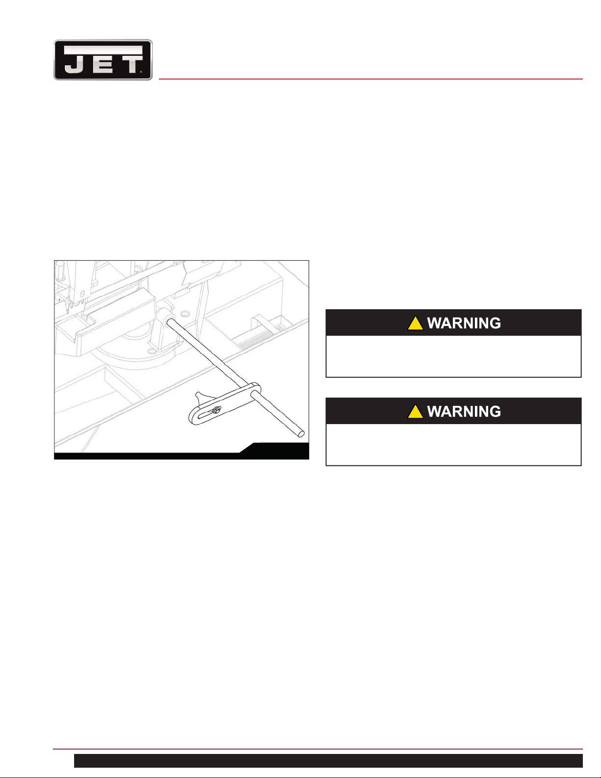
Thread the stop rod (A) into the threaded opening on the
front of the saw bed (B) as shown.
Set the work stop as follows:
1. Loosen the stop arm (C).
2. Position the stop arm (C) on the stop rod (A) to
obtain the desired length of cut on the workpiece
(D).
3. Rotate the stop arm (C) so it contacts the end of the
workpiece (D).
4. Secure the stop arm.
Channels
S q ua res/Rec t an gles
Hexagonals
Angles
I-B eam s
Kn ock off sharp ed g
here with file
Tees
Fig. 11
11.9 SETTING THE WORK STOP
Referring to Figure 12:
The work stop is an accessory that is included with the Jet
EHB-8 Bandsaw. It is used to set up the saw for making
multiple cuts of the same length.
!
CAUTION
Do not allow the blade to rest on the workpiece
when the saw is not cutting.
C
A
B
D
Fig. 12
12.0 ADJUSTMENTS
12.1 BLADE TRACKING ADJUSTMENT
Refer to Figures 13 and 14.
Blade tracking has been set and tested at the factory.
Adjustment is rarely required when the blade is used
properly or if the blade is correctly welded.
If adjustment is needed:
1. Using the blade tension handwheel (D), make sure
the blade is properly tensioned.
Keep proper tension at all times.
Note: Blade tensioning is described in the Changing
Blades section on page 17.
EHB-8VS | EHB-8VSM
2. Raise the saw head (A) as shown.
3. Open the wheel guards (B).
4. Remove both of the blade-guide bearing
bracket assemblies (C).
5. Loosen three hex locking screws (E) in the
head weldment (G).
13
Page 14

A
1
B
8. Turn the adjustment screws (F) to stop the motion of
the blade on the wheel as it gets closer to the wheel
shoulder.
Put a 6-inch length of paper (J, Fig. 14) between the
blade and the wheel as shown (the saw is still turned
C
on). The paper should not be cut as it passes
between the wheel shoulder and the blade.
9. Turn the adjustment screws (F) slightly.
Repeat the insertion of the paper between the wheel
shoulder and the blade until the paper is cut in two
1
G
E,F
2
E
pieces.
D
2
E,F
F
G
Fig. 13
!
CAUTION
While performing the following, keep the blade from
rubbing excessively on the shoulder of the wheel.
Excessive rubbing will damage the wheel and/or the
blade.
6. Start the saw. Turn the adjustment screws (F) to tilt
the idler wheel (Figure 14) until the blade is touching
the shoulder of the idler wheel.
Note: As a general rule, make the same adjustment to
the two adjustment screws on the right (F, Fig. 13). The
single adjustment on the left is independent.
7. Next, turn the adjustment screws (F) so the blade
starts to move away from the shoulder of the wheel
then immediately turn the adjustment screws in the
other direction so the blade stops – then moves slowly
toward the shoulder.
!
Keep fingers clear of the blade and wheel to
avoid injury.
J, Place paper here
Blade
Tension
Handwheel
Lifting
Handle
Idler Wheel
Fig. 14
Note: You may have to repeat the check with the paper
several times before the blade and the shoulder cut the
paper into two pieces. Do not hurry the adjustment.
Patience and accuracy here will pay off with better, more
accurate, quieter cutting and much longer machine and
blade life.
When the paper is cut:
10. Turn the adjustment screws (F) slightly in the counter-
clockwise direction. This ensures that the blade is
not touching the shoulder of the wheel.
11. Shut off the saw.
12. Tighten the hex locking screws (E).
13. Install the blade-guide bearing bracket assemblies
(C, Fig. 13).
14. Position the guides so the top bearing just touches
the blade (see Blade Guide Bearing Adjustment on
page 16) .
15. Close the wheel covers (K, Fig. 15).
14
8-in x 13-in Horizontal Cut-Off Bandsaw
Page 15

12.2 BLADE GUIDE ADJUSTMENT
Referring to Figure 15:
The EHB-8 Bandsaw has two adjustable blade guide
assemblies, each consisting of the blade guide support or
bracket (B, H) and blade guide (A).
The position of the blade guides is important in order to
make accurate cuts and prolong blade life and is determined
by the size of the workpiece. Adjustment is made as follows:
Left Blade Guide
1. Place the workpiece (G) in the vise (F) and clamp
tightly (refer to Work Setup on page 8).
2. Loosen the left lock knob (C) only.
3. Slide the guide support (D) left or right so that it just
clears the piece to be cut (G).
4. Tighten the lock knob (C).
Right Blade Guide
The right blade guide assembly is set at the factory and rests
against the stop (E). It normally does not require adjustment,
except to provide clearance for workpieces to be cut at a
great angle. If adjustment is required, the procedure is the
same as for the left blade guide adjustment.
It is always better to try a new blade when cutting
performance is poor. If performance remains poor after
changing the blade, check the blade guides for proper
spacing. For most efficient operation and maximum
accuracy, clearance between the blade and the guide
bearings should be 0.001 inch. The bearings will still turn
freely with this clearance. If the clearance is incorrect, the
blade tracking may be affected.
A
B
C
D
C
A
G
E
F
K
Fig. 15
12.3 BLADE GUIDE BEARING ADJUSTMENT
Referring to Figure 16:
Guide bearings and guide inserts are located on either side
of the saw blade and provide stability for the blade when the
saw is in operation. These bearings rotate on an eccentric
shaft so the distance from the blade can be adjusted for
optimal performance.
Blade guides provide blade support.
Guide bearings and blade guides are initially adjusted at
the factory and should rarely require adjustment
D
E
F
D
E
Fig. 16
!
Disconnect the cut-off saw from its electrical
power source.
!
Check the blade to make sure the welded section is
the same thickness as the rest of the blade. If the
blade is thicker at the weld, the guide bearings may
be damaged.
EHB-8VS | EHB-8VSM
15
Page 16

If required, adjust first one guide bearing and blade guide
assembly then the other as follows:
1. Using a 3mm hex wrench, loosen two set screws (A)
securing the eccentric bushings.
2. Using a 5mm hex wrench, loosen two socket head
cap screws (D) securing the carbide blade guides
(E).
3. Position the bearings (B) by turning the bushings
(C) with a flat-head screwdriver. Set the clearance
between the bearings (B) and blade (F) at
approximately 0.001 inch.
When properly adjusted, the blade should be in a
vertical position between the bearings as shown in
Figure 17.
4. Tighten the set screws (A).
5. Adjust the blade guides (E) so they support the blade
without pinching and tighten the socket head cap
screws.
6. When the adjustment is correct, the guide bearings
should rotate freely with slight pressure of the finger
(blade stopped).
12.5 VERIFYING ADJUSTMENT ACCURACY
Refer also to Figure 18.
T est cuts can be used to determine whether or not you have
adjusted the blade accurately . Use 2 inch round bar stock to
perform these test cuts, as follows:
1. With the bar stock securely clamped in the vise,
make a cut through the bar stock.
2. Mark the top of the bar stock.
3. Move the bar stock about 1/4 inch past the blade so
you can begin a second cut.
4. Rotate the bar stock 180 degrees so the mark you
made is now at the bottom of the cut.
5. Make a cut through the bar stock.
6. Use a micrometer to measure the thickness variation
between the top and bottom of the disk you have cut
from the bar stock.
The saw blade can be considered correctly adjusted when
the variation measured is no more than 0.012 inch across
the face of the disk. If you do not have a piece of 2-inch
bar stock available for a test cut, use a larger diameter
test workpiece rather than a smaller one. The maximum
thickness variation on any test piece should be no more
than 0.006 in. per inch of stock diameter.
INCORRECT CORRECT
Outer
Roller
Saw Blade
Inner
Roller
Locking Screw
Saw Blade
Fig. 17
12.4 DRIVE BELT TENSION ADJUSTMENT
The drive belt will stretch with use and may occasionally re-
quire tension adjustment. To adjust see the Changing Drive
Belt section (page 18) steps 1, 2, 6, and 7.
1. Clamp vise and mart top of bar stock here
2. Cut of a slice of
Rod
3. Rotate stock in vise
5. Measure
here ...
7. Difference between
measurements at edges
of disc should be less than
0.006 inches per inch of
6. ... and measure
here
stock di am et er
the bar stock
so mark is at bottom
4. Cu t o ff a new
slice from the
stock
Fig. 18
16
8-in x 13-in Horizontal Cut-Off Bandsaw
Page 17

12.6 LIMIT SWITCH ADJUSTMENT
!
Disconnect the cut-off saw from its electrical
power source.
Referring to Figure 19:
Loosen the jam nut and set the adjustment screw so that
the limit switch will actuate to the off position when the saw
has cut through the workpiece.
Hydraulic Cylinder
Limit Switch
to 1-1/2 inches are exposed on the right side of the
eyebolt mount.
The saw can now be returned to service.
Spring
Adjustment Nut
Eyebolt
Fig. 20
13.0 MAINTENANCE
Switch Actuator
Adjustment Screw
Jam Nut
Fig. 19
12.7 COUNTERBALANCE SPRING TENSION
!
Disconnect the cut-off saw from its electrical
power source.
The counterbalance spring is located on the rear of the saw
table (refer to Figure 20). The counterbalance spring is used
to adjust the amount of down force the saw arm puts on the
workpiece when the hydraulic control cylinder is fully open.
If adjustment is needed:
1. Raise the saw arm to its full upright position and lock
it in position.
2. Set the spring tension by adjusting the nut until 1-1/4
13.1 CHANGING BLADES
!
Use leather gloves when changing the saw blade
to protect your hands from cuts and scratches.
Use protective eye wear that meets ANSI
Specification Z87.1
!
Disconnect the cut-off saw from its electrical
power source.
Referring to Figure 21 (pg. 18):
1. Raise the saw head (A). Set the feed rate control
knob to zero to lock the hydraulic cylinder, which
will hold the saw head in place.
2. Open two hinged blade wheel covers (C).
3. Remove the blade guard (D) and column blade cover
(E).
4. Turn the blade tension handle (F) counter-clockwise
until the blade hangs loose.
EHB-8VS | EHB-8VSM
17
Page 18

5. Using leather gloves to prevent cuts and scratches,
pull the blade off the drive wheels (H) and out of
the blade guides (J). Store the removed blade
carefully before proceeding.
6. Slide the new blade into the blade guides (J), then
loop the blade around the drive wheels (H) such
that the teeth face towards the back and the smooth
side faces towards the front.
This will permit the vertical side of the teeth
to contact the workpiece first.
7. Push the blade so it is seated against the
shoulders of the wheels (H).
When it is seated against the shoulder, turn the blade
tension handle (F) clockwise to increase the tension.
Do not over-tension the blade; tighten it just enough
so it does not slip while cutting.
8. When the blade is properly tensioned, reconnect the
saw to the electrical power source.
9. Check and adjust the tracking of the blade. Refer to
Blade Tracking Adjustment (on page 14) if necessary.
10. Close the wheel covers (C).
11. Put 2 to 3 drops of oil on the blade.
1. Set the arm at the full horizontal position.
2. Open the drive belt cover to expose the drive belt and
pulleys.
3. Loosen the belt tension adjust knob located in the
rear under the motor (see Figure 23 for knob
direction). Lift the motor upward to loosen the belt.
4. Remove the worn drive belt.
5. Put the replacement drive belt in the pulley position for
the speed you require (refer to the Blade Speeds
section on page 9).
6. Tighten the drive belt by turning the belt tension
adjustment knob (see Figure 23). The belt must be
secure enough it does not slip when the machine is
running. Do not over tighten. This will cause prema-
ture wear on belt and pulley bearings.
7. Reinstall drive belt cover and install knob.
Motor
Motor Pulley
E
A
C
H
F
D
C
J
13.2 CHANGING THE DRIVE BELT
Referring to Figures 22 and 23:
!
Disconnect the cut-off saw from its electrical
power source.
Fig. 21
Motor
Belt T ension
Adjust Knob
Drive Belt Pulley
Lock
Nut
Drive Belt
Fig. 22
Fig. 23
18
8-in x 13-in Horizontal Cut-Off Bandsaw
Page 19

13.3 REPLACING THE DRIVE MOTOR
!
Disconnect the cut-off saw from its electrical
power source.
Referring to Figure 24:
1. Remove the drive belt (see Changing the Drive
Belt above).
2. Open the motor junction box and disconnect the
power cord wires from their terminals.
3. Remove four screws and washers (A) that secure the
motor (B) to the mounting plate (C).
4. Installation of a new motor is a reversal of the above
steps. Also, refer to Changing the Drive Belt (page 18)
to complete tensioning of the drive belt.
B
A
C
Fig. 24
4. Clean the chip sludge from the coolant tank. The
frequency should be determined by how often the
saw is used.
15.0 LUBRICATION
Lubricate the following components at the specified
frequencies and using the lubricants defined as follows:
Ball Bearings – the bearings are lubricated and sealed –
periodic lubrication is not required.
Blade Guide Bearing – the bearings are lubricated and
sealed – periodic lubrication is not required.
Upper Wheel Bushing – six to eight drops of oil each week.
Pivot Points, Shafts, and Bearing areas – six to eight drops
of oil each week.
16.0 COOLANT
Change coolant on a frequency appropriate to the type of
coolant being used. Oil based coolants can sour. Refer to
the coolant supplier’s instructions for change frequency.
The general-purpose coolant is a mixture of water-soluble
oil and water. Mix one part of soluble oil to ten parts of
water (one quart of oil to ten quarts water). Eleven quarts
of coolant is the amount required for the coolant pump to
operate properly.
There are numerous coolants on the market that are
formulated for special applications. Consult your local
distributor for details in the event you have a long range
production task, or are required to cut some of the more
exotic materials.
14.0 CLEANING
1. Clean off any preservative on machine surfaces.
After cleaning:
2. Coat machined surfaces of the cutoff saw with a
medium consistency machine oil. Reapply the oil
coating at least every six months.
3. Clean up accumulated saw cuttings after use. Make
sure the lead screw and rapid nut are kept free from
saw cuttings and other material that would cause
damage.
EHB-8VS | EHB-8VSM
19
Page 20

17.0 TROUBLESHOOTING
Fault Probable Cause Suggested Remedy
Excessive blade breakage
1. Material loose in vise.
2. Incorrect speed or feed.
3. Teeth too coarse for material.
4. Incorrect blade tension.
5. Saw blade is in contact with work
piece before the saw is started.
6. Blade rubs on the wheel flange.
7. Misaligned guides.
8. Cracking at weld.
1. Clamp work securely.
2. Check Machinist’s Handbook for
speed/feed appropriate for the
material being cut.
3. Check Machinist’s Handbook for
recommended blade type.
4. Adjust blade tension to the point
where the blade just does not slip on
the wheel.
5. Start the motor before placing the
saw on the workpiece.
6. Adjust blade tracking.
7. Adjust guides.
8. Longer annealing cycle.
Premature blade dulling
Bad cuts (crooked)
1. Blade teeth too coarse.
2. Blade speed too high.
3. Inadequate feed pressure.
4. Hard spots in workpiece or scale on
in workpiece.
5. Work hardening of material
(especially stainless steel).
6. Insufficient blade tension.
7. Operating saw without pressure on
workpiece.
1. Workpiece not square with blade.
2. Feed rate too fast.
3. Guide bearings not adjusted properly.
4. Inadequate blade tension.
5. Span between the two blade guides
too wide.
6. Dull blade.
7. Incorrect blade speed.
8. Blade guide assembly is loose.
9. Blade guide bearing assembly loose.
10. Blade track too far away from wheel
flanges.
11. Guide bearing worn.
1. Use a finer tooth blade.
2. Try a lower blade speed.
3. Decrease spring tension.
4. Increase feed pressure (hard spots).
Reduce speed, increase feed
pressure (Scale).
5. Increase feed pressure by reducing
spring tension.
6. Increase tension to proper level.
7. Do not run blade at idle in/on
material.
1. Adjust vise so it is square with the
blade. (Always clamp the workpiece
tightly in the vise.)
2. Decrease feed rate.
3. Adjust guide bearing clearance to
0.001 inch (0.002 inch maximum).
4. Gradually increase blade tension.
5. Move blade guide bracket closer to
work.
6. Replace blade.
7. Check blade speed
(refer to Figure 5).
8. Tighten blade guide assembly.
9. Tighten blade guide
bearing assembly.
10. Adjust blade tracking.
11. Replace worn bearing.
20
8-in x 13-in Horizontal Cut-Off Bandsaw
Page 21

Fault Probable Cause Suggested Remedy
Bad cuts (rough)
1. Blade speed too high for
feed pressure.
2. Blade is too coarse.
1. Reduce blade speed and
feed pressure.
2. Replace with finer blade.
Blade is twisting
Unusual wear on side/back of blade
1. Blade is binding in the cut.
2. Blade tension too high
1. Blade guides worn
2. Blade guide bearings
not adjusted.
3. Blade guide bearing bracket
is loose.
1. Decrease feed pressure.
2. Decrease tension on Blade
1. Replace blade guides.
2. Adjust blade guide bearings.
3. Tighten blade guide
bearing bracket.
EHB-8VS | EHB-8VSM
21
Page 22

18.0 REPLACEMENT PARTS EHB-8VS/VSM
To order parts or reach our service department, call
1-855-336-4032 Monday through Friday (see our website
for business hours, www.jettools.com). Having the Model
Number and Serial Number of your machine available when
you call will allow us to serve you quickly and accurately.
®
JET
427 New Sanford Road
LaVergne, Tennessee 37086
www.jettools.com
Ph.: 855-336-4032
22
8-in x 13-in Horizontal Cut-Off Bandsaw
Page 23

EHB-8VS SAW STAND & BED - PARTS BREAKDOWN
EHB-8VS | EHB-8VSM
23
Page 24

EHB-8VS SAW STAND & BED PARTS LIST
Index No. Part No. Description Size Qty.
1-1 TS-1499141 Hex Cap Screw M12x80 4
1-2 TS-1540081 Hex Nut M12 4
EHB8VS-2A Stand Assembly (Index 2-1 thru 2-5) 1
2-1 EHB8VS-2-1 Coolant Pan 1
2-2 EHB8VS-2-2 Right Leg 1
2-3 EHB8VS-2-3 Left Leg 1
2-4 EHB8VS-2-4 Front Panel/Shelf 1
2-5 EHB8VS-2-5 Back Door/Shelf 1
2-6 TS-0050031 Cross Head Hex Cap Screw 1/4"-20x3/4 10
2-8 TS-0561011 Hex Nut 1/4"-20 10
2-9 TS-0060051 Hex Cap Screw 3/8"-16x1 8
2-10 TS-0680041 Flat Washer 3/8" 16
2-11 TS-0561031 Hex Nut 3/8"-16 8
2-12 TS-1490071 Hex Cap Screw M8x40 8
2-13 TS-0680031 Flat Washer 5/16" 8
2-14 TS-1540061 Hex Nut M8 8
3 EHB8VS-3 Filter 1
4 TS-2246102 Button Head Socket Screw M6x10 1
5S EHB8VS-5S Electrical Box Assembly (Reference Only) 1
6-1 EHB8VS-6-1 Coolant Tank 1
6-2 EHB8VS-6-2 Hose 13x19-350mm 1
6-3 EHB8VS-6-3 Elbow PT1/2x1/4 1
6-4 EHB8VS-6-4 Coolant Pump 1/8HP,115/230V,1Ph 1
6-5 TS-0680021 Flat Washer 1/4" 4
6-6 TS-081F052 Pan Head Machine Screw 1/4"-20x3/4 4
6-7 EHB8VS-6-7 Hose Clamp 1
7 EHB8VS-7 Pivot Shaft 1
8S EHB8VS-8S Cylinder Assembly 1
9 EHB8VS-9 Ext. Retaining Ring S18 1
12 EHBS8VS-12 Cylinder Upper Bracket 1
13 TS-0720081 Lock Washer 5/16" 3
14 TS-1504061 Socket Head Cap Screw M8x30 3
15 TS-1505081 Socket Head Cap Screw M10x50 1
16S EHB8VS-16S Stock Stop Assembly (Index 16-1 thru 16-8)
not shown
16-1 EHB8VS-16-1 Bracket 1
16-2 TS-1550061 Flat Washer
16-3 EHB8VS-16-3 Lock Handle 2
16-4 EHB8VS-16-4 Distance Set Rod 1
16-5 EHB8VS-16-5 Shaft 1
16-6 TS-154010 Hex Nut M16 x P2.0 1
16-7 EHB8VS-16-7 Scale 1
16-8 TS-1540071 Rivet 4
17-1S EHB8VS-17-1S Hand wheel Assembly 1
17-2 TS-0680051 Flat Washer 7/16" 1
17-3 EHB8VS-17-3 Key 5x5x15L 1
17-4 EHB8VS-17-4 Acme Lead screw 1
17-5S EHB8VS-17-5S Acme Nut Assembly 1
M8
1
2
24
8-in x 13-in Horizontal Cut-Off Bandsaw
Page 25

Index No. Part No. Description Size Qty.
17-6 EHB8VS-17-6 Bracket 1
17-7 EHB8VS-17-7 Pin 1
24 TS-1505031 Socket Head Cap Screw M10x25 2
24-1 TS-2361101 Lock Washer M10 2
25 EHB8VS-25 Pivot Shaft Washer 2
26 EHB8VS-26 Support Bracket 1
26-1 EHB8VS-26-1 Gap Ring 2
28-1 EHB8VS-28-1 Tube ID1/2"x2.8tx126cm 1
28-2 EHB8VS-28-2 Hose Clamp Ø19mm 3
28-3 EHB8VS-28-3 Tube ID1/2"x2.8tx320cm 1
28-4 EHB8VS-28-4 Spray Gun 1
28-5 EHB8VS-28-5 3 Way Connector PT1/2" 1
29 EHB8VS-29 Position Set Bracket 1
30 TS-0680031 Flat Washer 5/16" 2
31 TS-1490031 Hex Cap Screw M8x20 2
32 EHB8VS-32 Rear Pivot Bracket 1
33 EHB8VS-33 Plate 1
34 TS-2361101 Lock Washer M10 2
35 TS-149105 Hex Cap Screw M10x35 2
36 EHB8VS-36 Bed 1
37 TS-2245102 Button Head Socket Screw M5x10 2
38 EHB8VS-38 Angle Scale 1
39 TS-1524021 Socket Set Screw M8x10 1
40 TS-1540061 Hex Nut M8 1
41 TS-1490081 Hex Cap Screw M8x45 1
42 EHB8VS-42 Front Moveable Vise Jaw 1
43 EHB8VS-43 Bushing 1
44 TS-1550071 Flat Washer M10 1
45 TS-1505051 Socket Head Cap Screw M10x35 1
46 EHB8VS-46 Washer ø10.5xø27xt3mm 1
47 EHB8VS-47 Bolt 1
48 EHB8VS-48 Socket Set Screw M8x30 2
49 EHB8VS-46 Washer ø10.5xø27xt3mm 1
50 EHB8VS-50 Locking Handle M10x37 1
51 EHB8VS-51 Rear Fixed Vise Jaw 1
52 TS-1523031 Socket Set Screw M6x10 1
53 EHB8VS-53 Bushing 1
54 TS-1506041 Socket Head Cap Screw M12x35 1
55 TS-0561031 Hex Nut 3/8"-16 1
56 TS-0680041 Flat Washer 3/8" 1
57 EHB8VS-57 Spring Bracket 1
58 EHB8VS-58 Spring Eye Bolt 1
59 EHB8VS-59 Spring 1
60 TS-0081031 Hex Cap Screw 5/16"-18x3/4" 1
61 TS-0680031 Flat Washer 5/16" 1
62 TS-1505051 Socket Head Cap Screw M10x35 1
63 TS-2360121 Flat Washer M12 1
64 TS-2361011 Spring Washer M12 1
EHB-8VS | EHB-8VSM
25
Page 26

Index No. Part No. Description Size Qty.
71 EHB8VS-71 Limit Switch Holder 1
72 TS-1534042 Pan Head Machine Screw M6x12 2
73 EHB8VS-73 Limit Switch 1
74 TS-1550021 Flat Washer M4 2
74-1 TS-1540021 Hex Nut M4 2
75 TS-2284302 Pan Head Machine Screw M4x30 2
117 EHB8VS-117 Pivot Shaft 1
402 EHB8VS-402 Swivel Bushing 2
403 EHB8VS-403 Control Column 1
405 TS-1490011 Hex Cap Screw M8 x 12 4
407 TS-1550061 Flat Washer M8 4
408 EHB8VS-301 Handle 1
409 EHB8VS-409 Control Box 1
411 EHB8VS-411 Lock Handle M8 x 20 1
412 EHB8VS-412 C-Ring S-36 4
413 EHB8VS-413 Control Panel 1
414 TS-2244102 Socket Head Button Screw M4 x 10 5
415 EHB8VS-415 Electric Lamp 1
416 EHB8VS-416 Start Switch 1
417 EHB8VS-417 Emergency Stop Switch 1
418 EHB8VS-418 Coolant Pump Switch 1
419 EHB8VS-419 Hydraulic Feed Control Knob 1
26
8-in x 13-in Horizontal Cut-Off Bandsaw
Page 27

EHB-8VSM SAW STAND & BED - PARTS BREAKDOWN
EHB-8VS | EHB-8VSM
27
Page 28

EHB-8VSM SAW STAND & BED PARTS LIST
Index No. Part No. Description Size Qty.
1-1 TS-1499141 Hex Cap Screw M12x80 4
1-2 TS-1540081 Hex Nut M12 8
6-3 EHB8VSM-6-3 Elbow PT1/2x1/4 1
6-4 EHB8VS-6-4 Coolant Pump 1/8HP,115/230V,1Ph 1
6-5 TS-0680021 Flat Washer 1/4" 4
6-6 TS-081F052 Pan Head Machine Screw 1/4"-20x3/4 4
7 EHB8VS-7 Pivot Shaft 1
8S EHB8VS-8S Cylinder Assembly 1
9 EHB8VS-9 Ext. Retaining Ring S18 1
12 EHBS8VS-12 Cylinder Upper Bracket 1
13 TS-0720081 Lock Washer 5/16" 3
14 TS-1504061 Socket Head Cap Screw M8x30 3
15 TS-1505081 Socket Head Cap Screw M10x50 1
16S EHB8VS-16S Stock Stop Assembly (Index 16-1 thru 16-8) 1
16-1 EHB8VS-16-1 Bracket 1
16-2 TS-1550061 Flat Washer
16-3 EHB8VS-16-3 Lock Handle 2
16-4 EHB8VS-16-4 Distance Set Rod 1
16-5 EHB8VS-16-5 Shaft 1
16-6 TS-154010 Hex Nut M16-2.0 1
16-7 EHB8VS-16-7 Scale 1
16-8 TS-1540071 Rivet 4
17-1S EHB8VS-17-1S Handwheel Assembly 1
17-2 TS-0680051 Flat Washer 7/16" 1
17-3 EHB8VS-17-3 Key 5x5x15L 1
17-4 EHB8VS-17-4 Acme Lead screw 1
17-5S EHB8VS-17-5S Acme Nut Assembly 1
17-6 EHB8VS-17-6 Bracket 1
17-7 EHB8VS-17-7 Pin 1
24 EHB8VSM-24 Locking Washer AW05 2
25 EHB8VSM-25 Locking Nut AN05 2
26 EHB8VS-26 Support Bracket 1
26-1 EHB8VS-26-1 Gap Ring 2
28-1 EHB8VS-28-1 Tube ID1/2"x2.8tx126cm 1
28-2 EHB8VS-28-2 Hose Clamp Ø19mm 3
28-3 EHB8VS-28-3 Tube ID1/2"x2.8tx320cm 1
28-4 EHB8VS-28-4 Spray Gun 1
28-5 EHB8VS-28-5 3 Way Connector PT1/2" 1
29 EHB8VS-29 Position Set Bracket 1
30 TS-0680031 Flat Washer 5/16" 2
31 TS-1490031 Hex Cap Screw M8x20 2
32 EHB8VS-32 Rear Pivot Bracket 1
33 EHB8VS-33 Plate 1
34 TS-2361101 Lock Washer M10 2
35 TS-149105 Hex Cap Screw M10x35 2
39 TS-1524021 Socket Set Screw M8x10 1
40 TS-1540061 Hex Nut M8 1
M8
2
28
8-in x 13-in Horizontal Cut-Off Bandsaw
Page 29

Index No. Part No. Description Size Qty.
41 TS-1490081 Hex Cap Screw M8x45 1
42 EHB8VS-42 Front Moveable Vise Jaw 1
43 EHB8VS-43 Bushing 1
44 TS-1550071 Flat Washer M10 1
45 TS-1505051 Socket Head Cap Screw M10x35 1
46 EHB8VS-46 Washer ø10.5xø27xt3mm 1
47 EHB8VS-47 Bolt 1
48 EHB8VS-48 Socket Set Screw M8x30 2
49 EHB8VS-46 Washer ø10.5xø27xt3mm 1
50 EHB8VS-50 Locking Handle M10x37 1
51 EHB8VSM-51 Rear Fixed Vise Jaw 1
52 TS-1523031 Socket Set Screw M6x10 1
53 EHB8VS-53 Bushing 1
54 TS-1506041 Socket Head Cap Screw M12x35 1
55 TS-0561031 Hex Nut 3/8"-16 1
56 TS-0680041 Flat Washer 3/8" 1
57 EHB8VS-57 Spring Bracket 1
58 EHB8VS-58 Spring Eye Bolt 1
59 EHB8VS-59 Spring 1
60 TS-0081031 Hex Cap Screw 5/16"-18x3/4" 1
61 TS-0680031 Flat Washer 5/16" 1
62 TS-1505051 Socket Head Cap Screw M10x35 1
63 TS-2360121 Flat Washer M12 1
64 TS-2361011 Spring Washer M12 1
71 EHB8VS-71 Limit Switch Holder 1
72 TS-1534042 Pan Head Machine Screw M6x12 2
73 EHB8VS-73 Limit Switch 1
74 TS-1550021 Flat Washer M4 2
74-1 TS-1540021 Hex Nut M4 2
75 TS-2284302 Pan Head Machine Screw M4x30 2
71 EHB8VS-71 Limit Switch Holder 1
72 TS-1534042 Pan Head Machine Screw M6x12 2
73 EHB8VS-73 Limit Switch 1
74 TS-1550021 Flat Washer M4 2
74-1 TS-1540021 Hex Nut M4 2
75 TS-2284302 Pan Head Machine Screw M4x30 2
117 EHB8VSM-117 Pivot Shaft 1
152 EHB8VSM-152 Base 1
153 EHB8VSM-153 Bushing 2
154 EHB8VSM-154 Shaft 1
155 EHB8VSM-155 Block M30-1.5 1
156 EHB8VSM-156 Idle Gear 1
157 EHB8VSM-157 Special Washer 1
158 EHBS8VSM-158 Gear 1
159 TS-1540081 Hex Nut M12 1
160 TS-2310181 Hex Nut M18-2.5 1
161 EHB8VSM-161 Handle Bar 1
161-1 EHB8VSM-161-1 Instruction Label 1
EHB-8VS | EHB-8VSM
29
Page 30

Index No. Part No. Description Size Qty.
162 EHB8VSM-162 Handle 1
164 EHB8VSM-164 Slide Base 1
165 EHB8VSM-165 Stop Bracket 2
166 EHB8VSM-166 Socket Head Cap Screw M10x40 3
167 EHB8VSM-167 Scale 1
168 EHB8VSM-168 Rivet M2x5 3
169 TS-1505131 Socket Head Cap Screw M10x80 3
169-1 TS-1505041 Socket Head Cap Screw M10x30 3
170 EHB8VSM-170 Rotation Base 1
171 EHB8VSM-171 Bracket 1
172 EHB8VSM-172 Base 1
172-1 EHB8VSM-172-1 Door 1
172-2 EHB8VSM-172-2 Back Cover 1
172-3 EHB8VSM-172-3 Side Cover 1
172-4 EHB8VSM-172-4 Hook 1
172-5 EHB8VSM-172-5 Chip Tray 1
173 EHB8VSM-173 Plug 1
174 EHB8VSM-174 Coolant Gauge 1
175 EHB8VSM-175 Bracket 1
176 EHB8VSM-176 Round Head Cross Screw M5x10 8
177 TS-1503041 Socket Head Cap Screw M6x15 2
178 TS-1550041 Flat Washer M6 2
180 EHB8VSM-180 Pointer 1
181 EHB8VSM-181 Round Head Cross Screw M6x10 1
182 TS-2361121 Lock Washer M12 1
401 EHB8VSM-401 Tube Bracket 1
402 EHB8VS-402 Swivel Bushing 2
403 EHB8VSM-403 Control Column 1
404 EHB8VSM-404 Cover 1
405 TS-1490011 Hex Cap Screw M8 x 12 8
406 EHB8VSM-406 Round Head Cross Screw M5x8 2
407 TS-1550061 Flat Washer M8 8
408 EHB8VS-301 Handle 1
409 EHB8VS-409 Control Box 1
411 EHB8VS-411 Lock Handle M8 x 20 1
412 EHB8VS-412 C-Ring S-36 4
413 EHB8VS-413 Control Panel 1
414 TS-2244102 Socket Head Button Screw M4 x 10 5
415 EHB8VS-415 Electric Lamp 1
416 EHB8VS-416 Start Switch 1
417 EHB8VS-417 Emergency Stop Switch 1
418 EHB8VS-418 Coolant Pump Switch 1
419 EHB8VS-419 Hydraulic Feed Control Knob 1
420 EHB8VSM-420 Water T ray 1
30
8-in x 13-in Horizontal Cut-Off Bandsaw
Page 31

SAW HEAD (BOTH MODELS) - PARTS BREAKDOWN
354-12
214
355-1
217
218
355
212
B
360-1
356
G
220-1
220-7
220-2
215-1
215-2
357
220-6
220-5
220-4
220-3
A
354-11
328
363
311
354-1
354-2
314-2
310
368
367
366
358
371
370
369
359
314-4
314-3
360
354-3
354-4
354-5
312
354-8
354-6
313
G
365
364
354-7
354-10
F
362
361
314
H
305
304
303
301
300
206
207
205
302
204
210
219
A
213
212
C
216
215
B
209
208
C
314-1
H
318
302-1
332
330-1
E
302-2
330
317
202
354-9
333
329
309
316
308
334
331
316-1
F
221
307
341
340
B
339
338
342
343
345S
337
336
335
*
319
*
*
*
327
FOR SV
351-1
352
*
*
*
*
*
*
326
325
351-3
314-5
314-6
322
351-2
321
323
320
345-2
350
351S
345-1
345-4
345-3
353
324
223-1
222-3
306-1
223
222-5
226
225
315-1
222-1
315
306
224
222-4
222-2
A
B
A
EHB-8VS | EHB-8VSM
211
200
209-1
31
Page 32

SAW HEAD (BOTH MODELS) PARTS LIST
Index No. Part No. Description Size Qty.
200 EHB8VS-200 Blade Guard 1
202 EHB8VS-202 Knob M6-1.0Px10L 2
204 TS-1504051 Socket Head Cap Screw M8x25 2
205 TS-1551061 Lock Washer M8 2
206 TS-1550061 Flat Washer M8 2
207 EHB8VS-207 Knob 2
208 TS-1550071 Flat Washer M10 2
209 EHB8VS-209 Blade Guide Support Arm 2
209-1 EHB8VS-209-1 Blade Direction Label 2
210 EHB8VS-210 Gib 2
211 EHB8VS-211 Ext. Retaining Ring ø8 4
212 BB-608ZZ Bearing 608ZZ 10
213 EHB8VS-213 Eccentric Guide 2
214 EHB8VS-214 Eccentric Guide 2
215 TS-1503051 Socket Head Cap Screw M6x20 4
215-1 TS-1550041 Flat Washer M6 4
215-2 TS-2361061 Lock Washer M6 4
216 EHB8VS-216 Carbide Guide 4
217 EHB8VS-217 Bearing Shaft 2
218 TS-1523011 Socket Set Screw M6x6 4
219 EHB8VS-219 Guide Bracket (Left) 1
220-1 EHB8VS-220-1 Valve 2
220-2 EHB8VS-220-2 Hose ø6 2
220-3 EHB8VS-220-3 Straight Connector 2
220-4 EHB8VS-220-4 Hold Down Clamp 2
220-5 TS-2361061 Lock Washer M6 2
220-6 TS-2246122 Button Head Socket Screw M6x12 2
220-7 EHB8VS-220-7 Horse Clamp 2
221 EHB8VS-221 Right Guide Bracket 1
EHB8VS-222S Brush Assembly (Index 222-1 thru 222-5) 1
222-1 EHB8VS-222-1 Brush Holder 1
222-2 EHB8VS-222-2 Blade Brush 1
222-3 TS-1550041 Flat Washer M6 2
222-4 TS-1540041 Hex Nut M6 2
222-5 TS-1482071 Hex Cap Screw M6x35 1
223 TS-2246102 Socket Head Button Screw M6x10 1
223-1 TS-2361061 Lock Washer M6 1
224 TS-2246122 Socket Head Button Screw M6x12 2
225 EHB8VS-225 Blade Brush Guard 1
226 TS-1540041 Hex Nut M6 2
300 TS-1503051 Socket Head Cap Screw M6-1.0Px20L 6
301 EHB8VS-301 Handle 2
302 EHB8VS-302 Knob 2
302-1 TS-1550031 Flat Washer M5 6
302-2 TS-2245102 Button Head Socket Screw M5x10 6
303 EHB8VS-303 Left Blade Wheel Cover 1
304 TS-2361061 Lock Washer M6 4
32
8-in x 13-in Horizontal Cut-Off Bandsaw
Page 33

Index No. Part No. Description Size Qty.
305 TS-2311061 Hex Nut M6-1.0P 4
306 EHB8VS-306 Right Blade Wheel Cover 1
306-1 EHB8VS-306-1 Padding Strip 2
307 TS-1490031 Hex Cap Screw M8x20 1
308 EHB8VS-308 Washer ø16xø30xt3mm 1
309 BB-6205VV Bearing 6205-2RS 2
310 EHB8VS-310 Idler Wheel 1
311 EHB8VS-311 Shaft 1
312 EHB8VS-312 Handle 1
313 TS-0561031 Hex Nut 3/8"-16 2
314 EHB8VS-314 Body Frame 1
314-1 EHB8VS-314-1 Connector PT1/2" 1
314-2 EHB8VS-314-2 Hose 18x24-190mm 1
314-3 EHB8VS-314-3 Stop Bolt 1
314-4 TS-1540061 Hex Nut M8 2
314-5 EHB8VS-314-5 Screen 1
314-6 EHB8VS-314-6 Round Head Screw M5-0.8Px10L 1
315 EHB8VS-315 Cover 1
315-1 EHB8VS-315-1 Knob 2
316 EHB8VS-316 Scale 1
316-1 EHB8VS-316-1 Rivet ø2x5L 2
317 TS-1506011 Socket Head Cap Screw M12x20 2
318 EHB8VS-318 Slide Bar 1
319 TS-1524051 Socket Set Screw M8x20 4
320 TS-1492021 Hex Cap Screw M12x30 1
321 TS-2361121 Lock Washer M12 1
322 EHB8VS-322 Drive Shaft Washer 1
323 EHB8VS-323 Key 7x7x30L 1
324 891091 Blade (Standard) 1x.035x114.5” - 5/8T 1
325 EHB8VS-325 Drive Wheel Key Slot 7mm 1
326 TS-1505021 Socket Head Cap Screw M10x20 3
327 TS-1551071 Lock Washer M10 3
328 EHB8VS-328 Gear Box Assembly 1:30 1
329 TS-1541041 Nylon Nut M10 2
330 EHB8VS-330 Shaft 1
330-1 EHB8VS-330-1 Knurled Disc 1
331 TS-1540081 Hex Nut M12 1
332 TS-1505101 Socket Head Cap Screw M10x60 1
333 EHB8VS-333 Motor Adjusting Screw 1
334 EHB8VS-334 Motor Mount Plate 1
335 EHB8VS-335 Motor Mount Plate Bracket 2
336 TS-1550041 Flat Washer M6 4
337 TS-1482041 Hex Cap Screw M6x20 4
338 EHB8VS-338 Motor 1.5HP,115/230V,1Ph 1
339 EHB8VS-339 Key 8x7x35L 1
340 TS-1550061 Flat Washer M8 4
341 TS-1490021 Hex Cap Screw M8x16 4
342 TS-1482011 Hex Cap Screw M6x10 2
343 TS-1550041 Flat Washer M6 2
EHB-8VS | EHB-8VSM
33
Page 34

Index No. Part No. Description Size Qty.
345 EHB8VS-345 Pulley Guard 1
345-1 EHB8VS-345-1 Pulley Cover 1
345-2 EHB8VS-345-2 Knob 2
345-3 EHB8VS-345-3 Bracket 1
345-4 EHB8VS-345-4 Cross Head Screw M5x8 2
350 EHB8VS-350 Belt V-330 1
351S EHB8VS-351S Variable Speed Pulley Set 1
351-1 EHB8VS-351-1 Motor Pulley 1
351-2 EHB8VS-351-2 Gear Box Pulley 1
351-3 EHB8VS-351-3 Speed Chart 1
352 EHB8VS-352 Key 7x7x37L 1
353 EHB8VS-353 Speed Chart Label 1
354-1 EHB8VS-354-1 Hose Clamp ø12 2
354-2 EHB8VS-354-2 Straight Connector PT1/4"x1/4" 1
354-3 EHB8VS-354-3 Elbow PT1/4"x1/4" 1
354-4 EHB8VS-354-4 Hose Clamp ø19 1
354-5 EHB8VS-354-5 Hose ID1/4"x2.2tx80cm 1
354-6 EHB8VS-354-6 3 Way Coolant Block 1
354-7 EHB8VS-354-7 Straight Connector PT1/4"x1/4" 1
354-8 TS-1503071 Socket Head Cap Screw M6x30 2
354-9 EHB8VS-354-9 Hose ID1/4"x2.2tx143cm 1
354-10 EHB8VS-354-10 Hose ID1/4"x2.2tx32cm 1
354-11 EHB8VS-354-11 Hose Clamp 2
354-12 EHB8VS-354-12 Cross Head Screw 2
355 EHB8VS-355 Hub 1
355-1 EHB8VS-355-1 Blade Tension Handle 2
356 BB-51203 Thrust Bearing 51203 1
357 EHB8VS-357 Tension Indicator 1
358 EHB8VS-358 Lock Washer Tension ID16.3x31.5x1.8t 10
359 EHB8VS-359 Tension Shaft 1
360 EHB8VS-360 Tension Slide Base 1
360-1 EHB8VS-360-1 Tension Scale 1
361 TS-1523051 Socket Set Screw M6x16 1
362 EHB8VS-362 Tension Slide Block 1
363 TS-154010 Hex Nut M16 1
364 EHB8VS-364 Washer 1
365 TS-1490031 Hex Cap Screw M8x20 1
366 EHB8VS-366 Screw 3
367 TS-2361101 Lock Washer M10 3
368 TS-1491101 Hex Cap Screw M10x60 3
369 EHB8VS-369 Plate 2
370 TS-2361081 Lock Washer M8 4
371 TS-1490011 Hex Cap Screw M8x12 4
372 TS-2246122 Button Head Socket Screw M6x12 2
373 TS-0680021 Flat Washer 1/4" 2
374 EHB8VS-374 Control Box 1
375 TS-2286121 Flat Head Machine Screw M6x12 2
376 EHB8VS-376 Control Box Front Panel 5 Hole 1
377 TS-1533032 Pan Head Machine Screw M5x8 4
34
8-in x 13-in Horizontal Cut-Off Bandsaw
Page 35

ELECTRIC ASSEMBL Y
Index No. Part No. Description Size Qty.
5-1 EHB8VS-5-1 Fuse Base 2
5-2 EHB8VS-5-2 Fuse 220V 1A 1
5-2-1 EHB8VS-5-2-1 Fuse 110V 2A 1
5-3 EHB8VS-5-3 Aluminum Rail 1
5-4 EHB8VS-5-4 Magnetic Contactor CU-18 1
5-5 EHB8VS-5-5 Overload Relay RHU-10K1 1
5-6 EHB8VS-5-6 Pump Contactor 1
5-7 EHB8VS-5-7 Limit Switch TM1309 1
5-12 EHB8VS-5-12 Transformer 110/220/24V 1
5-13 EHB8VS-5-13 Pan Head Machine Screw 3/16 x 3/8 15
5-14 EHB8VS-5-14 Electrical Control Box Cover 1
5-15 EHB8VS-5-15 Electrical Control Box Base 1
EHB8VS-ECB Electrical Control Box compound( included 5-14,5-15) 1
5-16 EHB8VS-5-16 Net Plate 1
5-17 EHB8VS-5-17 Cable Glands PG11 5
5-18 EHB8VS-5-18 Terminal Block 264-336 2
5-19 EHB8VS-5-19 Terminal Block 264-326 3
5-20 EHB8VS-5-20 Terminal Block 266-306 1
5-21 EHB8VS-5-21 Motor Cable 1
5-22 EHB8VS-5-22 Limit Switch Cable 1
5-23 EHB8VS-5-23 Power Cable 1
5-24 EHB8VS-5-24 Control Wire 1
5-25 EHB8VS-5-25 Pump Cable 1
5-26 EHB8VS-5-26 Pan Head Machine Screw M4 x 15 4
5-27 EHB8VS-5-27 Pan Head Machine Screw M3 x 15 2
5-28 EHB8VS-5-28 Fuse Base 1
5-29 EHB8VS-5-29 Fuse 2A 1
EHB-8VS | EHB-8VSM
35
Page 36

19.0 WIRING DIAGRAM EHB-8
1Ø〜
L
60HZ
110/220V
PE
KM1
FR:Overload
FU1:24V-2A FUSE
TC:Transformer
SB1:Emergency Stop
SB3:Start Switch
SB4:Pump Switch
KM1:Contactor
KM2:PUMP Contactor
L:Signal
SQ1:Limit Switch(MET1653)
FU2:220V-1A FUSE
FU3:110V-2A FUSE
M1:MAIN MOTOR
M2:COOLANT PUMP MOTOR
PE:GROUND
U1
M1
1~
W1
KM2
FR
U2
W2
M2
1〜
110V-2A
G0V
FU3
FU2
220V-1A
L
N
TC
78
FU1
2A
0
SQ1
L
24V
SB3
SB1
1
2
KM1
FR
3
36
PE
2.0MM
1/8HP
110/220/60HZ
2
1-1/2HP
110/220/60HZ
KM1
7
8-in x 13-in Horizontal Cut-Off Bandsaw
SB4
4
KM2
 Loading...