

Page 1

Operating Instructions and Parts Manual
Structural Dual-Miter Band Saw, 18”
Model ECB-1833DMEVS
®
JET
427 New Sanford Road
LaVergne, Tennessee 37086
www.jettools.com
Ph.: 855-336-4032
Document No. M-891170
Edition 1 12/2020
Copyright © 2020 JET
Page 2

1.0 WARRANTY AND SERVICE
JET® warrants every product it sells against manufacturers’ defects. If one of our tools needs service or repair, please
contact Technical Service by calling 1-855-336-4032, 8AM to 5PM CST, Monday through Friday.
WARRANTY PERIOD
The general warranty lasts for the time period specifi ed in the literature included with your product or on the offi cial JET
branded website, jettools.com.
WHO IS COVERED?
This warranty covers only the initial purchaser of the product from the date of delivery.
WHAT IS COVERED?
This warranty covers any defects in workmanship or materials subject to the limitations stated below. This warranty does not
cover failures due directly or indirectly to misuse, abuse, negligence or accidents, normal wear-and-tear, improper repair,
alterations or lack of maintenance.
HOW TO GET TECHNICAL SUPPORT
Please contact Technical Service by calling 1-855-336-4032. Please note that you will be asked to provide proof of initial
purchase when calling. If a product requires further inspection, the Technical Service representative will explain and assist
with any additional action needed. JET has Authorized Service Centers located throughout the United States. For the name
of an Authorized Service Center in your area call 1-855-336-4032 or use the Service Center Locator on the JET website.
2
Horizontal Band Saw
Page 3

MORE INFORMATION
JET® is constantly adding new products. For complete, up-to-date product information, check with your local distributor or
visit the JET website, jettools.com.
HOW STATE LAW APPLIES
This warranty gives you specifi c legal rights, subject to applicable state law.
LIMITATIONS ON THIS WARRANTY
JET LIMITS ALL IMPLIED WARRANTIES TO THE PERIOD OF THE LIMITED WARRANTY FOR EACH PRODUCT.
EXCEPT AS STATED HEREIN, ANY IMPLIED WARRANTIES OF MERCHANTABILITY AND FITNESS FOR A PARTICULAR
PURPOSE ARE EXCLUDED. SOME STATES DO NOT ALLOW LIMITATIONS ON HOW LONG AN IMPLIED WARRANTY
LASTS, SO THE ABOVE LIMITATION MAY NOT APPLY TO YOU.
JET SHALL IN NO EVENT BE LIABLE FOR DEATH, INJURIES TO PERSONS OR PROPERTY, OR FOR INCIDENTAL,
CONTINGENT, SPECIAL, OR CONSEQUENTIAL DAMAGES ARISING FROM THE USE OF OUR PRODUCTS. SOME
STATES DO NOT ALLOW THE EXCLUSION OR LIMITATION OF INCIDENTAL OR CONSEQUENTIAL DAMAGES, SO
THE ABOVE LIMITATION OR EXCLUSION MAY NOT APPLY TO YOU.
JET sells through distributors only. The specifi cations listed in JET printed materials and on offi cial JET website are given as
general information and are not binding. JET reserves the right to eff ect at any time, without prior notice, those alterations
to parts, fi ttings, and accessory equipment which they may deem necessary for any reason whatsoever. JET® branded
products are not sold in Canada by JPW Industries, Inc.
NOTE: JET is a division of JPW Industries, Inc. References in this document to JET also apply to JPW Industries, Inc., or
any of its successors in interest to the JET brand.
ECB-1833DMEVS
3
Page 4

2.0 TABLE OF CONTENTS
1.0 WARRANTY AND SERVICE ........................................................................................................................................2
2.0 TABLE OF CONTENTS ................................................................................................................................................4
3.0 IMPORTANT SAFETY INSTRUCTIONS ......................................................................................................................5
4.0 INTRODUCTION ..........................................................................................................................................................7
5.0 SPECIFICATIONS ........................................................................................................................................................8
6.0 UNCRATING AND ASSEMBLY ....................................................................................................................................8
7.0 INSTALLATION ............................................................................................................................................................9
8.0 COOLANT ....................................................................................................................................................................9
9.0 ELECTRICAL CONNECTIONS ..................................................................................................................................10
10.0 CONTROLS..............................................................................................................................................................10
10.1 AUXILIARY COOLANT HOSE............................................................................................................................. 11
11.0 ADJUSTMENTS .......................................................................................................................................................10
11.1 REMOVING AND INSTALLING BLADE ...............................................................................................................10
11.2 BLADE BREAK-IN ................................................................................................................................................11
11.3 ADJUSTING BLADE GUIDE POST ......................................................................................................................11
11.4 ADJUSTING BLADE GUIDES ..............................................................................................................................12
11.5 CHANGING BLADE SPEED ................................................................................................................................12
11.6 ADJUSTING FEED RATE .....................................................................................................................................12
11.7 VISE ADJUSTMENT .............................................................................................................................................13
11.8 SLIDING TOUCH BAR .........................................................................................................................................13
11.9 CUTTING ANGLE ADJUSTMENT ........................................................................................................................13
11.10 BLADE BREAK SENSOR ...................................................................................................................................14
11.11 BLADE TENSION AND TRACKING ...................................................................................................................14
11.12 POWERED CHIP BRUSH ..................................................................................................................................15
12.0 PRIOR TO OPERATION ..........................................................................................................................................15
13.0 GENERAL OPERATING PROCEDURE...................................................................................................................15
13.1 MANUAL LUBE SYSTEM ...................................................................................................................................15
14.0 USER-MAINTENANCE ............................................................................................................................................16
14.1 GENERAL MAINTENANCE .................................................................................................................................16
14.2 GEARBOX ............................................................................................................................................................16
14.3 MANUAL LUBE SYSTEM.....................................................................................................................................16
14.4 COOLANT ............................................................................................................................................................16
14.5 HYDRAULIC SYSTEM .........................................................................................................................................16
14.6 MACHINE STORAGE ..........................................................................................................................................17
14.7 BELT ADJUSTMENT ............................................................................................................................................17
14.8 ADDITIONAL SERVICING ....................................................................................................................................17
14.9 MAINTENANCE SCHEDULE ...............................................................................................................................18
15.0 REPLACEMENT PARTS ..........................................................................................................................................19
16.0 WIRING DIAGRAM ..................................................................................................................................................46
4
Horizontal Band Saw
Page 5

3.0 IMPORTANT SAFETY INSTRUCTIONS
Warning - To reduce risk of injury:
1. Read and understand the entire owner’s manual before attempting assembly or operation.
2. Read and understand the warnings posted on the machine and in this manual. Failure to comply with all of these
warnings may cause serious injury.
3. Replace the warning labels if they become obscured or removed.
4. This band saw is designed and intended for use by properly trained and experienced personnel only. If you are not
familiar with the proper and safe operation of a band saw, do not use until proper training and knowledge have been
obtained.
5. Do not use this band saw for other than its intended use. If used for other purposes, JET®, disclaims any real or implied
warranty and holds itself harmless from any injury that may result from that use.
6. Always wear ANSI Z87.1 approved safety glasses or face shield while using this band saw. Also use face or dust mask
if cutting operation is dusty. (Everyday eyeglasses only have impact resistant lenses; they are NOT safety glasses.)
7. Wear proper apparel: Do not wear loose clothing, necktie, rings, bracelets or other jewelry which may get caught in
moving parts. Non-slip footwear or anti-skid floor strips are recommended. Wear protective hair covering to contain long
hair.
8. Wear ear protectors (plugs or muffs) during extended periods of operation.
9. Do not operate this machine while tired or under the influence of drugs, alcohol or any medication.
10. Make certain the switch is in the OFF position before connecting the machine to the power supply.
11. Make certain the machine is properly grounded.
12. Make all machine adjustments or maintenance with the machine unplugged from the power source.
13. Remove adjusting keys and wrenches. Form a habit of checking to see that keys and adjusting wrenches are removed
from the machine before turning it on.
14. Avoid contact with coolant, especially guarding your eyes.
15. Keep hands and fingers away from the blade when the machine is running.
16. Never hand hold the material. Always use the vise and clamp it securely.
17. Always provide adequate support for long and heavy material.
18. Keep safety guards in place at all times when the machine is in use. If removed for maintenance purposes, use extreme
caution and replace the guards immediately after maintenance is complete.
19. Check damaged parts. Before further use of the machine, a guard or other part that is damaged should be carefully
checked to determine that it will operate properly and perform its intended function. Check for alignment of moving parts,
binding of moving parts, breakage of parts, mounting and any other conditions that may affect its operation. A guard or
other part that is damaged should be properly repaired or replaced.
Do not use power tools in damp/wet locations or other dangerous environments. Do not expose them to rain. Keep work
20.
area well lighted. Provide for adequate space surrounding work area and non-glare overhead lighting.
21. Keep work area clean. Cluttered areas and benches invite accidents. Keep the floor free of scrap material, oil and
grease.
Keep visitors a safe distance from the work area. Keep children away. Workshop should be childproof; padlocks, master
22.
switches, remove starter keys.
23. Give your work undivided attention. Looking around, carrying on a conversation and “horse-play” are careless acts that
can result in serious injury.
24. Maintain a balanced stance at all times so that you do not fall or lean against the blade or other moving parts. Do not
overreach or use excessive force to perform any machine operation.
25. Use the right tool at the correct speed and feed rate. Do not force a tool or attachment to do a job for which it was not
designed. The right tool will do the job better and more safely.
26. Use recommended accessories; improper accessories may be hazardous.
27. Maintain tools with care. Keep blade sharp and clean for the best and safest performance. Follow instructions for
lubricating and changing accessories.
ECB-1833DMEVS
5
Page 6

28. Maintain proper adjustment of blade tension, blade guides and thrust bearings.
29. Turn off the machine and disconnect from power before cleaning. Use a brush to remove chips or debris — do not use
bare hands.
30. Do not use compressed air to clean the machine. This creates flying metal debris and may wedge pieces into crevices
of the machine.
31. Do not stand on the machine. Serious injury could occur if the machine tips over.
32. Never leave the machine running unattended. Turn the power off and do not leave the machine until it comes to a
complete stop.
33. Be sure that the blade is not in contact with the workpiece when the motor is started. The motor shall be started and you
should allow the saw to come up to full speed before bringing the saw blade into contact with the workpiece.
34. Adjust left blade guide to just clear workpiece.
35. Do not open blade covers while machine is running.
36. Direction of feed — feed work into a blade or cutter against the direction of rotation of the blade or cutter only.
37. Installation work and electrical wiring must be done by qualifi ed electrician in accordance with all applicable codes and
standards.
38. Do not remove jammed pieces until blade has stopped.
39. Do not store combustible materials near or around machine.
WARNING: This product can expose you to chemicals including lead and benzene which are known to the State
of California to cause cancer and birth defects or other reproductive harm. For more information go to http://www.
p65warnings.ca.gov.
WARNING: Some dust, fumes and gases created by power sanding, sawing, grinding, drilling, welding and other
construction activities contain chemicals known to the State of California to cause cancer and birth defects or other
reproductive harm. Some examples of these chemicals are:
• lead from lead based paint
• crystalline silica from bricks, cement and other masonry products
• arsenic and chromium from chemically treated lumber
Your risk of exposure varies, depending on how often you do this type of work. To reduce your exposure to these
chemicals, work in a well-ventilated area and work with approved safety equipment, such as dust masks that are
specifically designed to filter out microscopic particles. For more information go to http://www.p65warnings.ca.gov/ and
http://www.p65warnings.ca.gov/wood.
Familiarize yourself with the following safety notices used in this manual:
This means that if precautions are not heeded, it
may result in minor injury and/or possible machine
damage.
This means that if precautions are not heeded, it
may result in serious or even fatal injury.
6
Horizontal Band Saw
Page 7

4.0 INTRODUCTION
This manual is provided by JET® covering the safe operation and maintenance procedures for a JET Model ECB-1833DMEVS.
This manual contains instructions on installation, safety precautions, general operating procedures, maintenance instructions
and parts breakdown. Your machine has been designed and constructed to provide consistent long-term operation if used
in accordance with the instructions set forth in this document.
If there are questions or comments, please contact your local supplier or JET. JET can also be reached at our web site: www.
jettools.com. Retain this manual for future reference. If the machine transfers ownership, the manual should accompany it.
This manual is not intended to be an exhaustive guide to band saw operation. Consult your supervisor for more detailed
instruction.
ECB-1833DMEVS
7
Page 8

5.0 SPECIFICATIONS
Model number ECB-1833DMEVS
Stock number 891170 891175
Capacities:
90° 18 in. (460 mm)
Round
Rectangle
Square
Blade size 1.61 x 0.051 x 240 in. (41x1.3x6100mm) M42 Wikus Bi-metal 3/4T
Blade wheel diameter 580 mm (22.8 in.)
Blade speed variable within 50 ~ 300 FPM
Main motor 7.5HP, 60Hz, 230V, 3Ph, 4P, 19.3A 7.5HP, 60Hz, 460V, 3Ph, 4P, 9.7A
45° 18 in. (460 mm)
60° 15 in. (380 mm)
90° 18 x 31-1/2 in. W (460 x 800 mm)
45° 18 x 20.8 in. W (460 x 530 mm)
60° 18 x 14.9 in. W (460 x 380 mm)
90° 18 x 18 in. (460 x 460 mm)
45° 18 x 18 in. (460 x 460 mm)
60° 14.9 x14.9 in. (380 x 380 mm)
Base rotary angle motor 1/5HP(150W), 60Hz, 230V, 3Ph,
4P, 1.2A
Oil pump 1HP, 60Hz, 230V, 3Ph, 4P, 60Hz, 3.3A 1HP, 60Hz, 460V, 3Ph, 4P, 60Hz, 1.7A
Coolant pump 1/8HP, 230V, 3Ph, 2P, 60Hz, 0.48A
(210mm)
Cutting angles 60° right, 45° left
Gear box ratio (main motor) 1:46
Gear box ratio (angle motor) 1:180
Gear box capacity 2L (1/2 Ga)
Bed height from fl oor 33-1/2 in. (850 mm)
Coolant capacity 20 L (5-1/4 gal.)
Overall dimensions 110 x 74.8 x 82.67 in. ( 2800 x 1900 x 2100 mm)
Shipping dimensions 126.37 x 48.22 x 95.67 in. (3210 x 1225 x 2430 mm)
Net weight - approx. 5060 lbs. (2300 kg)
Shipping weight - approx. 5500 lbs. (2500 kg)
Machine environment:
Temperature range: -10° to +50° C (14° to 122° F)
Relative humidity: < 90°
1/5HP(150W), 60Hz, 460V, 3Ph,
4P, 0.6A
1/8HP, 460V, 3Ph, 2P, 60Hz, 0.24A
(210mm)
The specifi cations in this manual were current at time of publication, but because of our policy of continuous improvement, JET reserves the right to change specifi cations at any time and without prior notice, without incurring obligations.
8
Horizontal Band Saw
Page 9

6.0 UNCRATING AND ASSEMBLY
Note: Read and understand the entire manual before
attempting setup or operation.
1. Finish uncrating the saw and inspect for damage.
Should any have occurred, contact your local
distributor.
2. Remove all bolts attaching machine to shipping base.
3. Clean all rust protected surfaces with kerosene or a
cleaner/degreaser to remove protective coating.
Do not use gasoline, paint thinner, or mineral spirits,
as these may damage painted surfaces.
4. Lubricate all slideways with SAE 10W oil.
Shipping contents:
1 Band Saw
2 Splash Trays
1 Test Piece
1 Product Manual
1 Product Registration Card
1 Tool Box Complete (#ECB1833DMEVS-TBC), contains:
1 Adjustable Wrench 12”
1 Set of Open-end Wrenches
1 Set of Hex Wrenches
2 Screwdrivers (cross-point and fl at blade)
4 Leveling Bolts with Nuts
Fig. 7-1
Fig. 7-2
7.0 INSTALLATION
Use a forklift to set the band saw into position. It is not
recommended that a crane be used. Place the machine
on a fl at and level foundation of reinforced concrete. Allow
room for servicing and for moving large stock around the
band saw when deciding upon a location for the machine.
Maintain a minimum distance of 5 ft. (1500 mm) from the
rear of the machine to the wall.
Level machine with the provided bolts and nuts, and anchor it to the foundation with anchor bolts. Fig. 7-1 shows
hole pattern. NOTE: Accuracy and manufacturing tolerance of the machine can only be guaranteed if machine is
properly installed and leveled.
All leveling bolts should support the weight of the
machine evenly.
ECB-1833DMEVS
Fig. 7-3
8.0 COOLANT
Cutting fl uid or coolant must be supplied by the operator.
See sect. 14.4 for information.
9
Page 10
9.0 ELECTRICAL CONNECTIONS
Electrical connections must be made by a qualifi ed
electrican in compliance with all relevant codes.
This machine must be properly grounded to help
prevent electrical shock and possible fatal injury.
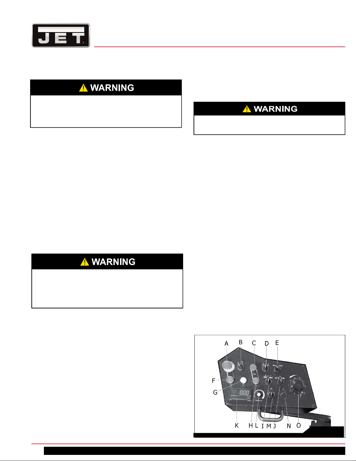
Hydraulic Start Button (F) - Press this fi rst to activate all
other functions on the panel.
Power Indicator Light (G) – Illuminated whenever
machine is connected to power.
If the bulb is out, lamp will not light, but machine
may still have power.
9.1 GROUNDING INSTRUCTIONS
The ECB-1833DMEVS Band Saw is prewired for 230V, 3
phase, or 460V, 3 phase. Confi rm that power available at
the saw’s location matches that for which the saw is wired.
The machine is not provided with an electrical plug; it can
be “hardwired” directly to a service panel.
Permanently connected tools: This tool should be connected to a grounded metal permanent wiring system; or
to a system having an equipment-grounding conductor.
Make sure a disconnect is available for the operator.
During hard-wiring of the machine, make sure the fuses
have been removed or the breakers have been tripped
in the circuit to which the band saw will be connected.
ALWAYS FOLLOW PROPER LOCK-OUT/TAG-OUT PROCEDURES.
Check with a qualifi ed electrician or service
personnel if the grounding instructions are not
completely understood, or if in doubt as to whether
the tool is properly grounded. Failure to comply may
cause serious or fatal injury.
10.0 CONTROLS
Main Motor Button (H) – Press to start motor and cutting
operation.
Vise Positioning (I) – Turn switch to position vise table
forward or back . CAUTION: Raise saw frame higher than
vise before moving vise table, to avoid machine damage.
Also, see note in Fig. 11.7 concerning removable table.
Vise Clamping (J) - Activates or releases clamping
action of the vise. Turn to the right and hold until clamping
pressure reaches 10-12 kg/cm².
Digital Readout (K) - Indicates blade speed during
machine operation, cutting angle when machine is
stopped.
Blade Speed (L) - Adjusts blade cutting speed; turn
clockwise to increase speed.
Angle Adjust Switch(M) - Turn to adjust cutting angle.
CAUTION: Be sure to raise saw frame higher than vise
height before moving angle to avoid machine damage.
Angle Rapid Adjust (N) - Press to quicken the angle
adjustment process. (Switch M must be turned at the
same time.)
Feed Rate Control (O) – Sets saw head speed of
descent, and thus the amount of pressure placed on the
workpiece by the blade. Turn counterclockwise to increase
feed rate.
Refer to Fig. 10-1.
The control box arm has wide swing adjustment for convenient positioning. The button functions are as follows.
Emergency Stop Button (A) – Press to immediately stop
all machine functions. Rotate clockwise to disengage.
Coolant Switch (B) – Turn switch to “I” to turn on coolant
fl ow. Turn switch to “O” to stop coolant fl ow. Flow is
regulated at the individual valves.
Stop Button (C) – Press to stop operation cycle.
Saw Head Movement (D) - Raises or lowers saw head.
Manual/Auto (E) - When Manual is selected, saw head
will remain down after cut. When Auto is selected, saw
head will return to raised position after cut.
10
Fig. 10-1
Horizontal Band Saw
Page 11

10.1 AUXILIARY COOLANT HOSE
The saw is equipped with an auxiliary coolant hose and
nozzle. This can be used when a larger fl ood of coolant
must be directed at the work piece, or when cleaning off
the lower sections of the saw.
11.0 ADJUSTMENTS
11.1 REMOVING AND INSTALLING BLADE
When your machine was shipped, a new blade was supplied and installed on the saw. When replacement becomes necessary, use a blade 0.051 in. (1.3mm) thick.
1. Raise saw head until blade clears the table. Close
feed rate dial by turning it clockwise as far as it will go.
2. Release blade tension using tension handle (see A,
Fig. 11-8).
3. Press E-stop button, and disconnect machine from
power.
4. Remove knurled screws and open the wheel covers.
5. Remove the two red blade guards, and back off the
carbide guides by turning the knurled adjustment
screws (see A Fig. 11-3).
6. Back off the chip brush on the drive wheel.
7. Remove the blade from both wheels and out of each
blade guide. CAUTION: Even dull blades are sharp
to the skin. Wear leather gloves when handling
blades.
8. Clean the swarf out of the blade wheel areas.
9. Make sure teeth of the new blade are pointing in the
direction of travel. If necessary, turn blade inside out.
10. Position blade on wheels. Make sure back of blade
rests lightly against wheel fl anges.
MAKE SURE THAT BACK OF BLADE IS AGAINST
FLANGES OF BOTH WHEELS, BUT NOT RUBBING
HARD AGAINST THEM.
15. Jog the blade “on” and “off ” to be sure the blade is in
place and tracking properly.
16. If blade is not tracking properly refer to sect. 11.11.
Otherwise blade installation is done.
17. Replace all guards, close all covers, and fasten
securely.
18. Follow blade break-in procedures, sect. 11.2.
11.2 BLADE BREAK-IN
A new blade should be “broken in” before normal,
extended use. Failure to break in a new blade will shorten
the service life of the blade, and result in ineffi cient cutting
performance.
1. Reduce blade speed to 1/2 of normal setting.
2. Set feed rate at 2 to 3 times longer than normal.
3. Make 5 complete cuts at the above settings, through
an 8-inch (200mm) diameter workpiece. Listen for
unusual noises or metallic sounds.
4. If no unusual sounds or other issues are detected,
then the blade is ready for normal operations.
11.3 ADJUSTING BLADE GUIDE POST
The blade guides should be set as close to the vise jaw as
possible. The right blade guide bracket is not adjustable
and is set at the factory to clear the right hand vise jaw.
The left blade guide post can be moved left or right
depending on the position of the sliding vise jaw.
To move blade guide post, loosen handle (R, Fig. 11-1),
slide post into position as close to workpiece as possible
without causing obstruction, then retighten handle.
The accompanying scale measures distance of exposed
blade between the blade guides.
11. Twist blade and slip it into the blade guides with back
of blade against the top carbide guide. NOTE: If roller
bearings need adjusting refer to sect. 11.4.
12. When you are sure the back of the blade is against the
wheel fl anges of both wheels and properly inserted
into the guides, reconnect power to the saw and
release E-stop.
13. Turn handle (A, Fig. 11-8) to tension blade.
14. Reposition chip brush so that it contacts the blade,
and tighten in place.
ECB-1833DMEVS
R
Fig. 11-1
11
Page 12
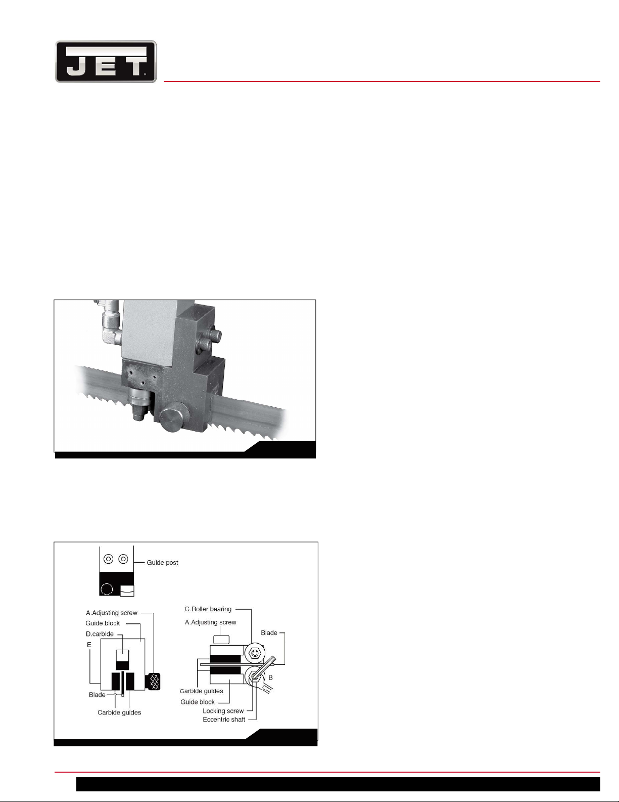
11.4 ADJUSTING BLADE GUIDES
Proper adjustment of blade guide bearings is critical to
effi cient operation of the saw. The band saw is shipped
with the blade tensioned and blade guides properly set.
They will rarely require adjustment except after a blade
change. Failure to maintain proper blade guide settings
may cause inaccurate cuts and/or blade damage.
First verify that the blade is sharp and in good condition;
properly adjusted guides will not compensate for an
inferior blade.
Fig. 11-2 shows the left hand blade guide assembly;
Fig. 11-3 shows the right hand. Adjustments for both are
identical.
Fig. 11-2
The back of the blade should ride against the upper
carbide guide (D, Fig. 11-3) which is positioned to provide
greater support and prevent defl ection at the back of the
blade.
The saw blade should also ride between the two roller
bearings (B) and (C) and the carbide blocks (E).
Use the adjusting screw (A) to lightly press the carbide
blocks against the surface of the blade.
The front and rear roller bearing guides are mounted to
eccentric shafts. Loosen the locking screws with a 6mm
hex wrench and turn the eccentric shaft with a 17mm open
end wrench until the bearing just contacts the blade. See
Fig. 11-3 Retighten the locking screw while holding the
eccentric shaft with the wrench to prevent it from turning.
Do this for both bearings then repeat for other guide
assembly.
IMPORTANT: If bearing positions are properly set, they
should not be readjusted. Under daily operation and/
or normal maintenance, make adjustments using the
adjustment screws (A) to position the carbide guides
against the blade. Constant adjustment of the bearings
may aff ect longevity of the saw blade and cutting
accuracy.
11.5 CHANGING BLADE SPEED
1. Raise cutting head approximately six inches above
work piece and turn feed rate knob (O, Fig. 10-1) to
zero.
2. Turn power on and turn speed adjuster knob (see
L, Fig. 10-1) to match appropriate material. The
LED display will show the current speed. Consult a
machinery handbook for recommended speeds for
various materials.
11.6 ADJUSTING FEED RATE
Rate of feed is adjusted with control dial (O, Fig. 10-1).
12
Feed rate is important to band saw performance;
excessive pressure may break the blade or stall the saw.
Insuffi cient pressure rapidly dulls the blade.
Material chips and shavings are the best indicator of
proper feed pressure. The ideal chip is thin, tightly
curled, and warm to the touch. Chips that range from
golden brown to black indicate excessive force. Blue
chips indicate extreme heat from too high a blade speed;
this will shorten blade life. Thin, powdery chips indicate
insuffi cient feed pressure.
Fig. 11-3
Horizontal Band Saw
Page 13
11.7 VISE ADJUSTMENT
The vise system is equipped with knurled pin (A) and vise
rack with 6 holes. See Fig. 11-4.
1. Place workpiece between vise jaws with required
amount to be cut off extending out past the blade.
2. If clamping smaller workpiece (width less than
6in./150mm) position pin A in same hole as shown in
Fig. 11-4.
3. For larger workpieces (wider than 6in./150mm), move
pin A to more suitable hole, such as hole B.
4. Turn clamp switch (see J, Fig. 10-1) to the right to
clamp the workpiece.
5. Perform cut.
6. Release clamping pressure by turning switch (J, Fig.
10-1) to the left.
The movable vise table can be moved forward or back to
accommodate the angle of the blade. Use switch I, Fig.
10.
IMPORTANT: A removable steel plate is located in front
of the blade, for additional support of workpieces during
straight cuts. Lift out this plate before moving the vise
table into forward position. If needed, return this plate to
its place when vise has been returned to rear position.
the head from rising higher than 35mm (1.8in.) from the
workpiece, where it awaits control panel input for the next
sequence. This results in greater effi ciency of time and
movement when cutting workpieces of the same size.
Also, when motor is started and feed rate is set, the
head will descend rapidly until the touch bar contacts the
workpiece, at which instant the head will slow to the feed
rate selected on control panel.
Fig. 11-5
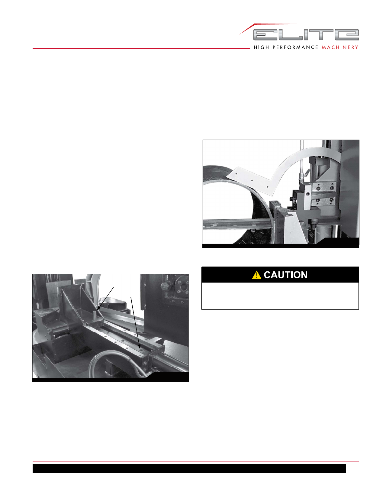
11.9 CUTTING ANGLE ADJUSTMENT
A
B
Fig. 11-4
11.8 SLIDING TOUCH BAR
When machine is set to Auto mode (switch E, Fig. 10-1)
the saw head will return automatically to raised position.
The touch bar, shown in Fig. 11-5, rests loosely against
the workpiece and alongside the cutting path, and
disconnects a limit switch inside the wheel guard. As
the saw head returns to raised position, the bar leaves
the workpiece and contacts the limit switch. This stops
Before adjusting angle, raise saw head/blade higher
than vise to prevent collisions and possible damage
to machine.
Angle adjustment is controlled by an angle calculator and
a frequency inverter.
Raise saw head to clear vise, and turn switch M, (see Fig.
10-1). Press button N simultaneously to increase speed
of positioning. When desired angle nears on the LED
display, release button N and use the slower speed for
fi nal positioning.
If the saw frame is moved to the greater angles, the
provided splash trays can be mounted on the lip of the
base at front or rear, to prevent coolant spill on the fl oor.
See A, Fig. 11-6.
The indicator scale (B, Fig. 11-6) is an alternate method
for angle measurement, and will show the same
measurement as the LED display on the control panel.
The LED display may have a variance of ±0.2 degrees.
ECB-1833DMEVS
13
Page 14

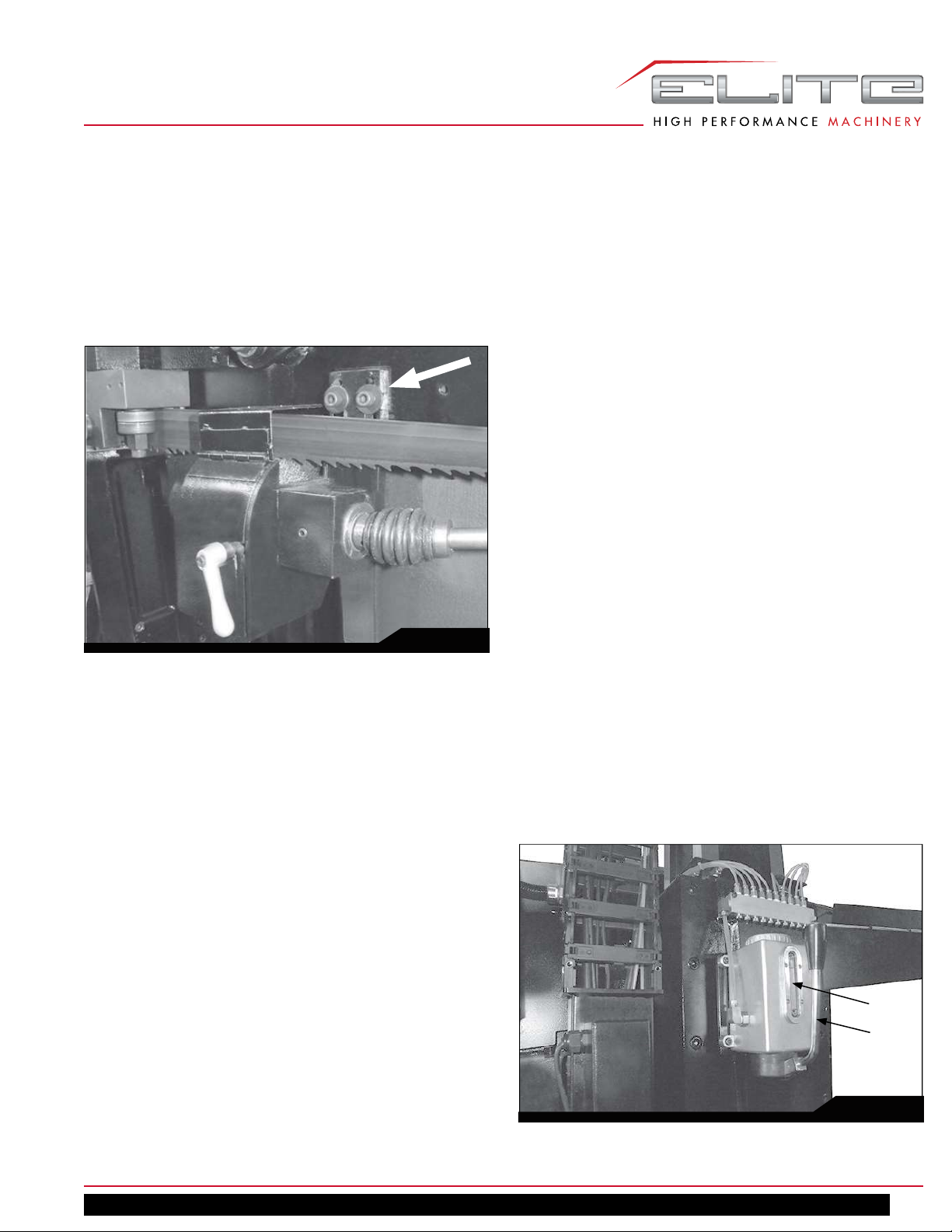
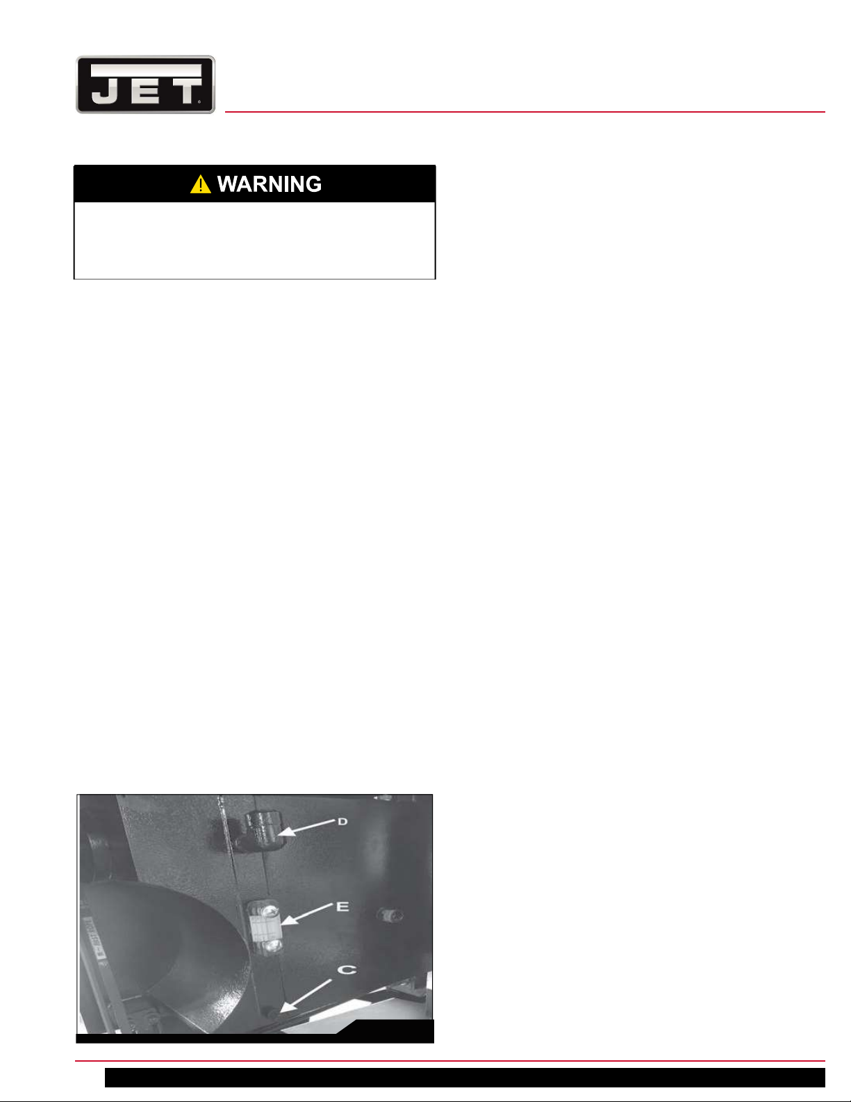
11.11 BLADE TENSION & TRACKING
B
A
Fig. 11-6
11.10 BLADE BREAK SENSOR
A sensor is positioned near the drive wheel. If the blade
breaks or has insuffi cient tension, the sensor switch will
shut off the saw to prevent further damage.
Fig. 11-7
Turn handle (A, Fig. 11-8) clockwise to tighten the blade,
or left to detension it for blade replacement.
Blade tension has been preset by the manufacturer for
the supplied blade. Tension is shown in the gauge above
the handle; proper tension will be in the green area, about
1800~2000 kgs/cm² Do not overtension blades.
CAUTION: Tracking adjustments must be performed
by qualifi ed persons who are familiar with this type of
adjustment and the dangers associated with it.
The saw blade has been properly tracked from the factory.
If a tracking problem occurs, proceed as follows:
1. Raise saw head to a convenient position if desired.
2. Open blade covers and inspect blade. The back edge
of the blade should make light contact with the fl ange
of the drive wheel.
3. Locate tracking adjustment bolts on the backside of the
saw head behind the idler wheel (Fig. 11-8).
4. Turn on saw blade at low speed.
5. Loosen center screw (C, Fig. 11-8).
6. Turn adjustment screw (D, Fig. 11-8) until blade back is
lightly contacting wheel fl ange. Blade should not rub
hard against the fl ange.
7. When satisfi ed, shut off blade and tighten center
screw (C) to secure setting. (Note: Hold adjustment
screw with the wrench while tightening center screw to
prevent further adjustment.)
IMPORTANT: If band saw will remain idle for an extended
period, back off blade tension (A) to reduce unnecessary
wear on wheels and components.
14
CD
A
Fig. 11-8
Horizontal Band Saw
Page 15
11.12 POWERED CHIP BRUSH
The wire brush is driven by the motor via the belt. Keep
the brush in contact with the blade to prevent excess
debris from entering the wheel track; this will help prolong the life of the blade. To adjust, loosen the 2 socket
head screws (A, Fig. 11-9). After positioning, retighten the
screws.
13.0 GENERAL OPERATING
PROCEDURE
1. Adjust left blade guide bracket as close as possible to
the left vise jaw, without causing obstruction.
2. Use the controls to raise the saw head, and turn the
feed rate dial to zero.
3. Move working table forward or back into the required
position based on cutting angle.
4. Adjust the angle of cut.
5. Place the stock between the vise jaws, position the
stock for the desired length of cut and clamp it with the
vise.
6. Start the blade and turn on coolant system. Adjust
coolant fl ow using the individual valves.
7. Set feed rate until saw blade begins to lower at desired
rate of speed.
8. Proceed to cut through the workpiece. The blade will
shut off at end of cut in manual mode; the saw head
will return to raised position in auto mode.
Fig. 11-9
12.0 PRIOR TO OPERATION
1. Verify that correct blade is installed for type of material
being cut.
2. Check that blade tooth direction matches arrows on
red blade guides.
3. Check to see that blade is properly seated on wheels
and correct blade tension is applied.
4. Adjust carbide guides if needed. See sect. 11.4.
5. Position left blade guide as close to workpiece as
possible without obstruction.
6. Select proper speed and feed rate for material being
cut.
7. Material to be cut must be securely held in vise.
8. Check to see that coolant level is adequate. If needed,
add coolant by pouring into chip tray so that it drains
through the strainer into basin.
9. Do not start cut on a sharp edge.
10. Keep machine lubricated. See sects. 13.1 and 15.0.
13.1 MANUAL LUBE SYSTEM
See Fig. 13-1.
Pump handle (A, Fig. 13-1) once per 8 hours of operation
to circulate oil to key places on the machine.
CAUTION: Do not pump multiple times - this may cause
the connecting hose to burst or come loose.
Check oil level daily in the sight glass (B); top off if needed
with hydraulic oil. See sect. 14.0.
B
A
ECB-1833DMEVS
Fig. 13-1
15
Page 16
14.0 USER-MAINTENANCE
Before doing maintenance on the machine,
disconnect it from the electrical supply by switching
off the main switch. Failure to comply may cause
serious injury.
14.1 GENERAL MAINTENANCE
Use a light machine oil to lubricate moving parts and
contact areas, as needed.
Vacuum or brush swarf from machine. Do not use bare
hands.
Periodically clean the sump in the machine base to extend
pump life and promote effi cient cutting. Change coolant
regularly at intervals recommended by coolant supplier.
All ball bearings are permanently lubricated and sealed.
They require no further attention.
14.2 GEARBOX
After the fi rst 50 hours of use the gear case should be
drained and refi lled. Change lubricant from then on every
6 months. Top off as needed.
To drain and refi ll:
1. Disconnect machine from power source.
2. Remove drain plug (C, Fig. 14-1) and allow gear oil
to drain completely. Dispose of oil according to local
regulations.
3. Wrap drain plug threads with thread sealant tape, and
reinstall plug.
4. Use fi ll plug (D) to fi ll gear box with Mobilube™ HD
85W140, or eqivalent. Capacity is 6L (1.58 Ga.). Do
not allow the oil level to fall below the Low mark on the
sight glass (E).
14.3 MANUAL LUBE SYSTEM
The manual lube system shown in Fig. 13-1 uses
hydraulic oil. Remove the cap on top to fi ll.
Use clean, new hydraulic oil to fi ll, NOT used oil.
Correct oil type is based upon the environment. ISO
32, 46, and 68 are common viscosities for diff erent
temperature ranges. Consult a hydraulic oil manufacturer’s
chart when selecting oil for your location.
The discharge amount has been properly set by the
manufacturer, but the amount can be adjusted if needed.
14.4 COOLANT
JET off ers a bio-degradable, concentrated fl ood coolant
(not provided) formulated for band saws, lathes, and
milling machines, with a 20:1 water/coolant mix ratio. See
JET website for more information and to order.
414124 JET Bio-Degradable Flood Coolant, 1/2 Gal.
414126 JET Bio-Degradable Flood Coolant, 1 Gal.
414127 JET Bio-Degradable Flood Coolant, 5 Gal. Pail
Filling and Draining
Pour coolant mixture into chip tray so that it drains through
strainer into basin. The sight glass is located on right side
of base.
To drain coolant use drain plug located on right side of
machine base. Follow local regulations when disposing of
used machine fl uids. Apply thread sealing tape to the drain
plug before re-installing.
Keep the overfl ow hole on right side of base, clean and
unobstructed.
Diff erent brands of coolant may not mix properly. If
changing to an alternate brand, fi rst fl ush coolant line and
sump with an industrial degreaser or cleaner that does not
contain silicone or petroleum based ingredients.
16
Fig. 14-1
14.5 HYDRAULIC SYSTEM
Check fl uid level using sight glass. See Fig. 14-2. If low,
pull out entire tank assembly, and pour Mobil™ Hydraulic
Oil ISO AW68, or equivalent, into the fi ll hole. Reinstall fi ll
plug. Tank capacity = 38L (10 gal.)
Pressure adjustment
Oil pressure for vise operation has been correctly
set by the manufacturer; no adjustment is needed.
Recommended clamping pressure should fall between 10
to 12 kg/cm² (142.2 to 170.6 psi).
Horizontal Band Saw
Page 17

Fig. 14-2
If future adjustment becomes necessary, turn knob A
counterclockwise to reduce pressure. See Fig. 14-2.
NOTE: If workpiece is thin, it is preferable to use a jig
instead of adjusting the hydraulic pressure.
DO NOT turn knob B, and DO NOT change pressure
setting of hydraulic work table. The work table may
move too rapidly and cause a safety hazard.
14.7 BELT ADJUSTMENT
If pulley slips or generates noise during operation, adjust
the tension knob (Fig. 14-3) clockwise to tighten the belt.
Fig. 14-3
14.8 ADDITIONAL SERVICING
Any additional servicing should be done by qualifi ed
service personnel.
14.6 MACHINE STORAGE
If the band saw is to be out of use for an extended period,
the following steps are recommended:
1. Disconnect from power supply.
2. Loosen tension on the blade.
4. Empty the coolant tank.
5. Clean and grease the machine.
6. Cover the machine if needed.
ECB-1833DMEVS
17
Page 18

14.9 MAINTENANCE SCHEDULE
If routine maintenance is neglected, the result will be premature wear and poor performance.
DAILY:
• General cleaning of machine; remove accumulated shavings. (Note: Do not use compressed air.)
• Clean coolant drain hole to avoid excess fl uid buildup in the trough.
• Top off the lubricating coolant.
• Check blade for wear.
• Raise saw head to top position and partially slacken the blade to avoid unneccesary yield stress.
• Check functioning of blade guards and E-stop button
WEEKLY:
• Thoroughly clean the machine to remove swarf, especially from the coolant tank.
• Clean fi lter of pump head and suction area.
• Use brush to clean blade guides, especially the guide bearings.
• Clean strainer and hole over the coolant basin.
• Clean blade wheel housings and races.
MONTHLY:
• Check tightness of drive wheel screws.
• Check that blade guide bearings are in perfect running condition.
• Check tightness of screws for motor, pump, and blade guards
EVERY SIX MONTHS:
• Perform circuit continuity checks.
• Drain and refi ll gearbox.
18
Horizontal Band Saw
Page 19

15.0 REPLACEMENT PARTS — ECB-1833DMEVS
Replacement parts are listed on the following pages.
To order parts or reach our service department, call
1-855-336-4032, Monday through Friday, 8 a.m. to 5
p.m. CST. Having the Model Number and Serial Number
of your machine available when you call will allow us to
serve you quickly and accurately.
®
JET
427 New Sanford Road
LaVergne, Tennessee 37086
www.jettools.com
Phone: 855-336-4032
ECB-1833DMEVS
19
Page 20

BASE ASSEMBLY — ECB-1833DMEVS
20
Horizontal Band Saw
Page 21

PARTS LIST BASE ASSEMBLY — ECB-1833DMEVS
Index No. Part No. Description Size Qty.
1 ECB1833DMEVS-A01 Base 1
2 ECB1833DMEVS-A02 Coolant Pump 1/8HP, 230/ 460V 3Ph 2P, 220L 1
3 ECB1833DMEVS-A03 Wires Sheet Metal Cover 1
4 ECB1833DMEVS-A04 Cooling Fan 1
5 ECB1833DMEVS-A05 Table Parallel Block 1
6 ECB1833DMEVS-A06 Rotary Arm 1
7 ECB1833DMEVS-A07 Adjustable Parallel Block 1
8 ECB1833DMEVS-A08 Front Auxiliary frame 1
9 ECB1833DMEVS-A09 Rear Auxiliary frame 1
10 ECB1833DMEVS-A10 Front Top Auxiliary Fram 1
11 ECB1833DMEVS-A11 Reae Top Auxiliary Fram 1
12 ECB1833DMEVS-A12 Terminal Box Set 1
13 ECB1833DMEVS-A13 Electric Box Cover 1
14 ECB1833DMEVS-A14 Oil Pump Box Cover 1
15 EHB916V-281-4 Lock W/Key 2
16 ECB1833DMEVS-A16 Chip Filter Net 1
17 ECB1833DMEVS-A17 Reae Top Auxiliary Fram 1
18 ECB1833DMEVS-A18 Dustproof Sheet 1
19 ECB1833DMEVS-A19 Turret Base ( Gears) 1
20 ECB1833DMEVS-A20 Rotary Arm Block Cover 1
21 ECB1833DMEVS-A21 Control Panel Set Assembly 1
22 ECB1833DMEVS-A22 Socket Head Flat Screw W1/4" x 1" 9
23 TS-0208061 Socket Head Cap Screw W5/16'' x 1'' 6
24 TS-0208031 Socket Head Cap Screw W5/16'' x 5/8'' 22
25 TS-0209061 Socket Head Cap Screw W3/8'' x 1-1/4'' 14
26 ECB1833DMEVS-A26 Washer 3/16'' 9
27 ECB1833DMEVS-A27 Socket Head Cap Screw W3/16'' x 3/8'' 9
28 ECB1833DMEVS-A28 Washer W3/8'' x 25 x 3.0 2
29 ECB1833DMEVS-A29 Hose Fitting 3/8''PT x 5/16''E 1
30 ECB1833DMEVS-A30 Washer 1/4" 4
31 TS-0207031 Socket Head Cap Screw W1/4" x 5/8" 4
32 ECB1833DMEVS-A32 Leval Screw W5/8" x 2" 6
33 ECB1833DMEVS-A33 Socket Head Cap Screw W3/16'' x 1/2'' 4
34 ECB1833DMEVS-A34 Plug 1/2''P 1
35 ECB1833DMEVS-A35 Oil Pump Set Assembly 1
36 ECB1833DMEVS-A36 Front Water Tray 1
37 ECB1833DMEVS-A37 Inverter 7.5HP/230V/3PH 1
38 ECB1833DMEVS-A38 Electrical components Set 1
39 ECB1833DMEVS-A39 Back Water Tray 1
ECB-1833DMEVS
21
Page 22

SWIVEL SEAT ASSEMBLY — ECB-1833DMEVS
22
Horizontal Band Saw
Page 23

PARTS LIST SWIVEL SEAT ASSEMBLY — ECB-1833DMEVS
Index No. Part No. Description Size Qty.
1 ECB1833DMEVS-B01 Center Fixed Plate Of Turret 1
2 ECB1833DMEVS-B02 Turret Base 1
3 ECB1833DMEVS-B03 Turret Shaft 1
4 ECB1833DMEVS-B04 Turret Shaft Bushing 1
5 ECB1833DMEVS-B05 Top Turret Block 1
6 SPB 809640 Self Lubrication Bearing SPB 809640 1
7 BB-80105 Thrust Bearing 80105 1
8 ECB1833DMEVS-B08 Shaft Nut 1
9 ECB1833DMEVS-B09 Top Plate 1
10 ECB1833DMEVS-G80 O-Ring G80 1
11 ECB1833DMEVS-B11 Angle calculator 45B 1
12 ECB1833DMEVS-B12 Fixed Table 1
13 ECB1833DMEVS-B13 Front Vise 1
14 ECB1833DMEVS-B14 Back Vise 1
15 ECB1833DMEVS-B15 Auxiliary Table 1
16 ECB1833DMEVS-B16 Front Support Block 1
17 ECB1833DMEVS-B17 Back Support Block 1
18 ECB1833DMEVS-B18 Angle Motor 1/5HP(150W),230/460V,3Ph ,4P 1
19 ECB1833DMEVS-B19 Oil Hydraulic Brake System 1
20 ECB1833DMEVS-B20 Angle Motor Plate 1
21 ECB1833DMEVS-B21 Brake Block 1
22 ECB1833DMEVS-B22 Gear 1
23 ECB1833DMEVS-B23 Angle Motor Protection Cover 1
25 ECB1833DMEVS-B25 Wire Collect Box 1
26 ECB1833DMEVS-B26 Wire Tube 1
27 ECB1833DMEVS-B27 Bracket 1
28 ECB1833DMEVS-B28 Metal Hose V2017+B2102 1
29 ECB1833DMEVS-B29 Strain Relief 7/8" 1
30 ECB1833DMEVS-B30 Strain Relief M16B(CSA) 4
31 ECB1833DMEVS-B31 Washer 1/4" 8
32 TS-0207031 Socket Head Cap Screw W1/4'' x 5/8'' 8
33 ECB1833DMEVS-B33 Hose Clamps 2" 1
34 ECB1833DMEVS-B34 Washer 3/16'' 6
35 ECB1833DMEVS-B35 Socket Head Cap Screw W3/16'' x 3/8'' 6
36 ECB1833DMEVS-B36 Top Protection Cover 1
37 TS-0209061 Socket Head Cap Screw W3/8'' x 1-1/4'' 22
38 TS-0209071 Socket Head Cap Screw W3/8'' x 1-1/2'' 8
39 TS-0209081 Socket Head Cap Screw W3/8'' x 1-3/4'' 9
40 ECB1833DMEVS-B40 Socket Head Cap Screw W3/16'' x 3/8'' 7
41 TS-0209091 Socket Head Cap Screw W3/8" x 2" 14
42 ECB1833DMEVS-B42 Spring Pin M10 x 40 2
43 TS-0208061 Socket Head Cap Screw W5/16'' x 1'' 4
44 TS-0208041 Socket Head Cap Screw W5/16'' x 3/4'' 4
45 ECB1833DMEVS-B45 Washer 3/16'' 3
46 TS-0720091 Lock Washer W3/8'' 4
47 ECB1833DMEVS-B47 Socket Head Cap Screw W3/16" x 5/8" 9
48 ECB1833DMEVS-B48 Round Head Machine Screw M3 x 19 3
49 TS-0267041 Socket Set Screw W1/4'' x 3/8'' 2
ECB-1833DMEVS
23
Page 24

Index No. Part No. Description Size Qty.
50 ECB1833DMEVS-B50 Brake Plate 1018T/1220T 1
51 TS-0561052 Hex Nut W1/2'' 1
52 ECB1833DMEVS-B52 Oil Hose Fitting 1/4''PT x1/4''TH 1
53 ECB1833DMEVS-B53 Oil Hose 1/4" x 1200 x B.L 1
55 ECB1833DMEVS-B55 Top Wires Collect Box 1
56 ECB1833DMEVS-B56 Cable Organizer 1
57 ECB1833DMEVS-B57 Socket Head Cap Screw W3/16'' x 1/2'' 12
58 ECB1833DMEVS-B58 Washer 3/16'' 4
59 ECB1833DMEVS-B29 Wires Sleeve 7/8" 3
60 ECB1833DMEVS-B60 Strain Relief PF 1/2" 1
61 ECB1833DMEVS-B61 Angle Caculator Plate 1
62 ECB1833DMEVS-B62 Buttom Plate 1
63 ECB1833DMEVS-B30 Strain Relief M16B(CSA) 1
HYDRAULIC CYLINDER ASSEMBLY— ECB-1833DMEVS
Index No. Part No. Description Size Qty.
1 ECB1833DMEVS-C01 Oil HyDraulic Cylinder 1
24
Horizontal Band Saw
Page 25

SLIDE ASSEMBLY — ECB-1833DMEVS
Index No. Part No. Description Size Qty.
1 ECB1833DMEVS-D01 Column 1
2 ECB1833DMEVS-D02 Front Column Sliding 1
3 ECB1833DMEVS-D03 Rear Column Sliding Cover 1
4 ECB1833DMEVS-D04 Gap 4
5 TS-0720131 Lock Washer 5/8" 18
6 ECB1833DMEVS-D06 Socket Head Cap Screw W5/8" x 2" 18
7 ECB1833DMEVS-D07 Socket Head Cap Screw W5/8" x 2 1/2" 12
8 ECB1833DMEVS-D08 Oil Distributor 1
9 ECB1833DMEVS-D09 Manual Oil Lubrication Pump 1
ECB-1833DMEVS
25
Page 26

SAW FRAME ASSEMBLY — ECB-1833DMEVS
26
Horizontal Band Saw
Page 27

PARTS LIST SAW FRAME ASSEMBLY — ECB-1833DMEVS
Index No. Part No. Description Size Qty.
1 ECB1833DMEVS-E01 Saw Bow 1
2 ECB1833DMEVS-E02 Driving Wheel Gasket 1
3 ECB1833DMEVS-E03 Driving Wheel 1
4 TS-0209081 Socket Head Cap Screw W3/8'' x 1-3/4'' 6
5 ECB1833DMEVS-E05 Idler Wheel 1
6 BB30210 Tapper Roller Bearing 30210 2
7 ECB1833DMEVS-AW10 Star Washer AW10 1
8 ECB1833DMEVS-AN10 Precision Nut AN10 1
9 ECB1833DMEVS-E09 Idler Wheel Dust Cover 1
10 ECB1833DMEVS-E10 Flat Washer 3/16'' 7
11 ECB1833DMEVS-E11 Round Head Machine Screw W3/16" x 3/8'' 3
12 ECB1833DMEVS-E12 Driven Wheel Cover 1
13 ECB1833DMEVS-E13 Idler Wheel Cover 1
14 891172 Blade 41x1.3x6100x3/4T 1
15 ECB1833DMEVS-E15 Limit Fixed Bracket 1
16 ECB1833DMEVS-E16 Limit Switch MN 5310 1
17 ECB1833DMEVS-E17 Air Hydraulic Set 600 N 2
18 ECB1833DMEVS-E18 Brush Wheel Cover 1
19 TS-0207031 Socket Head Cap Screw W1/4'' x 5/8'' 2
20 ECB1833DMEVS-E20 Round Head Machine Screw W5/32" x1-1/4'' 2
21 ECB1833DMEVS-E21 Socket Head Cap Screw W3/16'' x 3/8'' 4
ECB-1833DMEVS
27
Page 28

GEAR BOX ASSEMBLY — ECB-1833DMEVS
28
Horizontal Band Saw
Page 29

PARTS LIST GEAR BOX ASSEMBLY — ECB-1833DMEVS
Index No. Part No. Description Size Qty.
1 ECB1833DMEVS-F01 Gear Box 1
2 ECB1833DMEVS-F02 Shaft 1
3 ECB1833DMEVS-F03 Worm Gear 1
4 BB30214 Tapper Roller Bearing 30214 2
5 ECB1833DMEVS-F05 Oil Seal 709012 1
6 ECB1833DMEVS-AW14 Star Washer AW14 1
7 ECB1833DMEVS-AN14 Precision Nut AN14 1
8 ECB1833DMEVS-F08 Gear Box Cover 1
9 TC17020015 Oil Seal 17020015 1
10 ECB1833DMEVS-F10 Worm Shaft 1
11 ECB1833DMEVS-F11 Front Cover 1
12 ECB1833DMEVS-F12 Back Cover 1
13 BB30207 Tapper Roller Bearing 30207 2
14 BB6008 Ball Bearing 6008 1
15 ECB1833DMEVS-F15 Socket Head Cap Screw W5/8" x 2" 1
16 ECB1833DMEVS-F16 5/8" 7
17 TS-0208061 Socket Head Cap Screw W5/16'' x 1'' 6
18 TS-0207031 Socket Head Cap Screw W1/4'' x 5/8'' 8
19 TS-0207072 Socket Head Cap Screw W1/4" x 1-1/4" 3
20 ECB1833DMEVS-F20 Oil Seal 355510 1
21 TS-0561082 Hex Nut W3/4'' 3
22 ECB1833DMEVS-F22 Double Round Key 7 x 7 x 50 1
23 ECB1833DMEVS-F23 Pulley 1
24 ECB1833DMEVS-S40 C-Ring S-40 1
25 ECB1833DMEVS-F25 Socket Head Cap Screw W5/8" x 1-3/4" 6
26 ECB1833DMEVS-F26 Socket Set Screw W3/16'' x 3/16'' 1
27 ECB1833DMEVS-F27 Plug PT1/4'' 2
ECB-1833DMEVS
29
Page 30

MOVEABLE SEAT ASSEMBLY — ECB-1833DMEVS
30
Horizontal Band Saw
Page 31

PARTS LIST MOVEABLE SEAT ASSEMBLY — ECB-1833DMEVS
Index No. Part No. Description Size Qty.
1 ECB1833DMEVS-G01 Moveable Table 1
2 ECB1833DMEVS-G02 Wear-Resistant Plate 2
3 ECB1833DMEVS-G03 Vise Rack 1
4 ECB1833DMEVS-G04 Moveable Vise 1
5 ECB1833DMEVS-G05 Oil Hydraulic Cylinder Fixed bracket 2
6 ECB1833DMEVS-G06 Vise Fixed Pin 1
7 ECB1833DMEVS-G07 Oil Hydraulic Cylinder Set for Vise Clamp 1
8 ECB1833DMEVS-G08 Oil Hydraulic Cylinder Set for Moveable Table 1
9 ECB1833DMEVS-G09 Oil Hose Fitting 1/4''PT x 1/4''PT 1
10 ECB1833DMEVS-G10 3-Way Oil Distributor 1/4''PT x 3 1
11 ECB1833DMEVS-G11 Oil Pressure Meter 2.5AT-50KG 1
12 ECB1833DMEVS-G12 Oil Hose Fitting 1/4"P x1/4"P 1
13 ECB1833DMEVS-G13 90-deg. Oil Hose Fitting 1/4''PT x 1/4'T'H 2
14 ECB1833DMEVS-G14 Hi-Pressure Oil Hose 1/4" x 1500 x B.L 1
15 ECB1833DMEVS-G15 Oil Hose Fitting 1/8''PT x1/4''TH 2
16 ECB1833DMEVS-B53 Oil Hose 1/4" x 1200 x B.L 1
17 TS-0720091 Lock Washer W3/8'' 4
18 TS-0209061 Socket Head Cap Screw W3/8'' x 1-1/4'' 26
19 ECB1833DMEVS-G19 Socket Head Cap Screw W3/16'' x 7/8'' 4
20 TS-0267041 Socket Set Screw W1/4'' x 3/8'' 6
21 ECB1833DMEVS-G21 Oil Hydraulic Cylinder Pin 1
22 ECB1833DMEVS-B53 Oil Hose 1/4" x 1200 x B.L 2
ECB-1833DMEVS
31
Page 32

LEFT SIDE GUIDE ASSEMBLY — ECB-1833DMEVS
32
Horizontal Band Saw
Page 33

PARTS LIST LEFT SIDE GUIDE ASSEMBLY — ECB-1833DMEVS
Index No. Part No. Description Size Qty.
1 ECB1833DMEVS-H01 Slide Plate 1
2 ECB1833DMEVS-H02 Left Bearing Guide 1
3 ECB1833DMEVS-H03 Lock Block 1
ECB1833DMEVS-LBGA Left Bearing Guide Assembly Index no.5-18 1
5 ECB1833DMEVS-H05 Bearing Guide Bracket - left 1
6 ECB1833DMEVS-H06 Top Carbide Guide - left 1
7 ECB1833DMEVS-H07 Socket Head Cap Screw W3/16" x 5/8" 1
8 ECB1833DMEVS-H08 Lock Knob 1
9 ECB1833DMEVS-H09 Lock Shaft 1
10 ECB1833DMEVS-H10 Disc Spring 2
11 ECB1833DMEVS-H11 Carbide ( Front) 1
12 ECB1833DMEVS-H12 Carbide ( Rear) 1
13 ECB1833DMEVS-H13 Adjustable screw 2
14 BB-6201ZZ Ball Bearing 6201 ZZ 4
15 ECB1833DMEVS-H15 Flat Washer W5/16" 2
16 TS-0208031 Socket Head Cap Screw W5/16" x 5/8" 1
17 TS-0208102 Socket Head Cap Screw W5/16" x 2" 2
18 TS-0720081 Lock Washer W5/16'' 1
19 TS-0209061 Socket Head Cap Screw W3/8'' x 1-1/4'' 6
20 TS-0270041 Socket Set Screw W5/16'' x 5/8'' 9
21 TS-0209081 Socket Head Cap Screw W3/8'' x 1-3/4'' 2
22 TS-0720091 Lock Washer W3/8'' 2
23 ECB1833DMEVS-H23 Lock Handle M12 x 80 1
24 ECB1833DMEVS-H24 Flat Washer W1/2" 1
25 ECB1833DMEVS-H25 Connect Plug 1/4"P x 1/4"P 1
26 ECB1833DMEVS-H26 Adjusting Valve 1/4''P x 5/16''E 1
ECB-1833DMEVS
33
Page 34

RIGHT SIDE GUIDE ASSEMBLY — ECB-1833DMEVS
34
Horizontal Band Saw
Page 35

PARTS LIST RIGHT SIDE GUIDE ASSEMBLY — ECB-1833DMEVS
Index No. Part No. Description Size Qty.
1 ECB1833DMEVS-I01 Bearing Guide Block Seat 1
2 ECB1833DMEVS-I02 Bearing Guide Block 1
3 ECB1833DMEVS-H09 Lock Shaft 1
4 ECB1833DMEVS-H08 Lock Knob 1
5 ECB1833DMEVS-H10 Disc Spring 2
6 ECB1833DMEVS-I06 Top Carbide Guide, right 1
7 ECB1833DMEVS-I07 Socket Head Cap Screw W3/16" x 5/8" 1
8 ECB1833DMEVS-H12 Carbide ( Rear) 1
9 TS-0208031 Socket Head Cap Screw W5/16" x 5/8" 1
10 ECB1833DMEVS-H11 Carbide ( Front) 1
11 ECB1833DMEVS-H13 Adjustable screw 2
12 BB6201ZZ Ball Bearing 6201 ZZ 4
13 ECB1833DMEVS-I13 Flat Washer W5/16" 3
14 TS-0208102 Socket Head Cap Screw W5/16" x 2" 2
15 TS-0720091 Lock Washer W3/8'' 2
16 TS-0209081 Socket Head Cap Screw W3/8'' x 1-3/4'' 2
17 ECB1833DMEVS-H26 Adjusting Valve 1/4''P x 5/16''E 1
18 TS-0209061 Socket Head Cap Screw W3/8'' x 1-1/4'' 4
19 TS-0270071 Socket Set Screw W5/16'' x 3/4” 4
20 ECB1833DMEVS-I20 Coolant Hose 1/4" x 16" 1
21 ECB1833DMEVS-I21 Hose Connector 1/4''PT x 5/16''E 1
22 ECB1833DMEVS-H25 Connect Plug 1/4"P x 1/4"P 2
23 ECB1833DMEVS-I23 Adjusting Valve 1/4''P x 5/16''E 1
24 ECB1833DMEVS-I24 Stopper 1/4''PT 2
ECB-1833DMEVS
35
Page 36

MOTOR ASSEMBLY — ECB-1833DMEVS
Index No. Part No. Description Size Qty.
1 ECB1833DMEVS-J01 Upper Bracket 1
2 ECB1833DMEVS-J02 Middle Bracket 1
3 ECB1833DMEVS-J03 Buttom Bracket 1
4 ECB1833DMEVS-J04 Tension Knob 1
5 ECB1833DMEVS-J05 Flat Washer 1/2" 1
6 ECB1833DMEVS-J06 Motor Support Plate 1
7 ECB1833DMEVS-J07 Main Motor 7.5HP/ 230/460V, 3Ph ,4P 1
8 TS-0208081 Socket Head Cap Screw W5/16" x 1-1/2" 4
9 TS-0208092 Socket Head Cap Screw W5/16" x 1-3/4" 4
10 TS-0720091 Lock Washer W3/8'' 4
11 TS-0060051 Hex Cap Screw W3/8" x 1" 4
36
Horizontal Band Saw
Page 37

PULLEY ASSEMBLY — ECB-1833DMEVS
Index No. Part No. Description Size Qty.
1 ECB1833DMEVS-K01 PulleyBox- Buttom 1
2 ECB1833DMEVS-K02 Pulley Box-Cover 1
3 ECB1833DMEVS-K03 Lock Knob 2
4 ECB1833DMEVS-K04 Flat Washer 3/16'' 3
5 ECB1833DMEVS-I07 Socket Head Cap Screw W3/16" x 5/8" 3
6 ECB1833DMEVS-K06 Motor pulley 1
7 ECB1833DMEVS-K07 Gear Box pulley 1
8 VB-A37 V Belt A37 2
ECB-1833DMEVS
37
Page 38

SLIDING TOUCH BAR ASSEMBLY — ECB-1833DMEVS
Index No. Part No. Description Size Qty.
1 ECB1833DMEVS-L01 Rapid Down Feed Measuring Rod 1
2 ECB1833DMEVS-L02 Self- Lubrication Bearing CB1220 2
3 ECB1833DMEVS-L03 Contour Screw M12 x 45 1
4 TS-0051071 Hex Cap Screw W5/16'' x 1-1/2'' 2
5 TS-0570021 Hex Nut W5/16'' 2
38
Horizontal Band Saw
Page 39

BLADE TENSIONER ASSEMBLY — ECB-1833DMEVS
Index No. Part No. Description Size Qty.
ECB1833DMEVS-N01 Blade Tension Mechanism Set Index no.2-9 1
2 ECB1833DMEVS-N02 Blade Tension Bracket 1
3 ECB1833DMEVS-N03 Blade Tension Sliding Block 1
4 ECB1833DMEVS-N04 Slider Fixed Plate 2
5 ECB1833DMEVS-N05 Idler Shaft 1
6 TS-0208061 Socket Head Cap Screw W5/16'' x 1'' 8
7 TS-0208072 Socket Head Cap Screw W5/16'' x 1-1/4'' 4
8 ECB1833DMEVS-N08 Adjustable Screw 3
9 ECB1833DMEVS-N09 Socket Head Cap Screw W1/2'' x 3-1/2'' 3
11 ECB1833DMEVS-N11 Blade Tension Block 1
12 ECB1833DMEVS-N12 Handle 2
13 ECB1833DMEVS-N13 Shaft 1
14 ECB1833DMEVS-N14 Spring Pin M6 x 40 1
15 BB51104 Thrust Bearing 51104 1
16 ECB1833DMEVS-N16 Blade Tension Gauge 1
ECB-1833DMEVS
39
Page 40

WIRE BRUSH ASSEMBLY — ECB-1833DMEVS
40
Horizontal Band Saw
Page 41

PARTS LIST WIRE BRUSH ASSEMBLY — ECB-1833DMEVS
Index No. Part No. Description Size Qty.
1 ECB1833DMEVS-M01 Driven Brush Wheel set Index No 2-12 1
2 ECB1833DMEVS-M02 Pulley 1
3 ECB1833DMEVS-M03 Shaft 1
4 ECB1833DMEVS-M04 Double Round Key 5 x 5 x 20 1
5 ECB1833DMEVS-M05 Socket Set Screw W3/16'' x 5/16'' 1
6 ECB1833DMEVS-M06 Fixed Plate 1
7 ECB1833DMEVS-M07 Fixed Bracket 1
8 ECB1833DMEVS-M08 Shaft Fixed Seat 1
9 ECB1833DMEVS-SJ12 Universal Joint SJ-12 1
10 BB6001ZZ Ball Bearing 6001 ZZ 2
11 ECB1833DMEVS-M11 Flat Washer 1/4" 4
12 TS-0207061 Socket Head Cap Screw W1/4" x 1" 4
13 ECB1833DMEVS-M13 Idler brush Wheel Set Index no.14-28 1
14 ECB1833DMEVS-SJ12 Universal Joint SJ-12 1
15 ECB1833DMEVS-M15 Bruch Wheel Bracket 1
16 ECB1833DMEVS-M08 Shaft Fixed Seat 1
17 BB6001ZZ Ball Bearing 6001 ZZ 2
18 ECB1833DMEVS-M18 Brush Wheel Shaft 1
19 ECB1833DMEVS-M19 Brush Wheel Bracket 1
20 ECB1833DMEVS-M20 Brush Wheel Cover 1
21 ECB1833DMEVS-M06 Fixed Plate 1
22 ECB1833DMEVS-M22 Steel Brush D85xd7xB16 x0.3mm 1
23 ECB1833DMEVS-M23 Flat Washer 5/16" 2
24 TS-0570011 Hex Nut W1/4'' 1
25 TS-0207031 Socket Head Cap Screw W1/4'' x 5/8'' 4
26 ECB1833DMEVS-M26 Flat Washer 1/4" 8
27 TS-0207061 Socket Head Cap Screw W1/4" x 1" 4
28 ECB1833DMEVS-M28 Handle W1/4'' x 3/4'' 1
29 ECB1833DMEVS-M29 Connect Rod 1
30 VB-K40 Belt K40 1
ECB-1833DMEVS
41
Page 42

CONTROL BOX ASSEMBLY — ECB-1833DMEVS
Index No. Part No. Description Size Qty.
1 ECB1833DMEVS-O01 Indicator Lamp 1
2 ECB1833DMEVS-O02 Green Push Button -light 2
3 ECB1833DMEVS-O03 Red Push Button 1
4 ECB1833DMEVS-O04 Select Switch 6
5 ECB1833DMEVS-O05 Black Push Button 1
6 ECB1833DMEVS-O06 Valve Regulator Knob 1
7 ECB1833DMEVS-O07 Blade Speed Knob 1
8 ECB1833DMEVS-O08 Handle 1
9 ECB1833DMEVS-O09 Control Panel Box 1
10 ECB1833DMEVS-O10 Control Panel 1
11 ECB1833DMEVS-O11 Digital Readout Monitor 1
12 ECB1833DMEVS-O12 Socket Head Button Screw 7
13 ECB1833DMEVS-O13 Round Head Machine Screw W1/4" x 3/4'' 2
14 ECB1833DMEVS-O14 Flat Washer 1
15 ECB1833DMEVS-O15 Lock Handle 1
16 ECB1833DMEVS-O16 Emergency Stop Button 1
17 ECB1833DMEVS-O17 Valve Regulator 1
42
Horizontal Band Saw
Page 43

HYDRAULIC UNIT ASSEMBLY — ECB-1833DMEVS
Index No. Part No. Description Size Qty.
1 ECB1833DMEVS-P01 Oil Tank 1
2 ECB1833DMEVS-P02 Oil Tank Cover 1
3 ECB1833DMEVS-P06 Oil level Gauge 1
4 ECB1833DMEVS-P07 Oil Motor 1
5 ECB1833DMEVS-P10 Oil Pump 1
6 ECB1833DMEVS-F27 Plug 1
7 ECB1833DMEVS-P03 Reduce Valve Regulator 2
8 ECB1833DMEVS-P05 Check Valve 3
9 ECB1833DMEVS-P04 Solenoid Valve 2
10 ECB1833DMEVS-P08 Oil Circuit Board 1
11 ECB1833DMEVS-P09 Check Valve 1
12 ECB1833DMEVS-P12 Check Valve 1
13 ECB1833DMEVS-G11 Oil Pressure Gauge 2.5AT-50KG 1
ECB-1833DMEVS
43
Page 44

ELECTRICAL BOX DIAGRAM — ECB-1833DMEVS
44
Horizontal Band Saw
Page 45

PARTS LIST ELECTRICAL BOX — ECB-1833DMEVS
Index No. Part No. Description Size Qty.
1 VFDS1-INV Inverter S1 230V 1
VFDS1-INV460 Inverter S1 460V 1
2 EHB1833DMEVS-TC1 Transformer 200VA 1
3 EHB1833DMEVS-QS1 Door Switch 1
4 EHB1833DMEVS-FU1-2 Fuse 4A/230V 1
EHB1833DMEVS-FU1-4 Fuse 2A/460V 1
EHB1833DMEVS-FU2-2 Fuse 4A/230V 1
EHB1833DMEVS-FU2-4 Fuse 2A/460V 1
EHB1833DMEVS-FU3 Fuse 4A 1
EHB1833DMEVS-FU4 Fuse 4A 1
5 EHB1833DMEVS-KM1 Magnetic Switch CU-11/ 110V 1
6 EHB1833DMEVS-FR1-2 Overload for Coolant Pump 0.35-0.5A( 230V) 1
EHB1833DMEVS-FR1-4 Overload for Coolant Pump 0.16-0.25A( 460V) 1
7 EHB1833DMEVS-KM2 Magnetic Switch CU-11/ 110V 1
8 EHB1833DMEVS-FR2-2 Overload for Hydraulic Motor 2.5-4A(230V) 1
EHB1833DMEVS-FR2-4 Overload for Hydraulic Motor 1.4-2A(460V) 1
9 EHB1833DMEVS-KT1 Timer 10Sec/ 110V 1
10 EHB1833DMEVS-KA1 Relay MY4/ 110V 1
11 EHB1833DMEVS-KA2 Relay MY4/ 110V 1
12 EHB1833DMEVS-KA3 Relay MY2/ 110V 1
13 EHB1833DMEVS-KA4 Relay MY2/ 110V 1
14 ECB1833DMEVS-A37-2 Inverter 7.5HP/230V/3PH 1
ECB1833DMEVS-A37-4 Inverter 7.5HP/460V/3PH 1
ECB-1833DMEVS
45
Page 46

16.0 WIRING DIAGRAM
46
Horizontal Band Saw
Page 47

ECB-1833DMEVS
47
Page 48

48
Horizontal Band Saw
Page 49

CS1 MANUAL/AUTO
CS2 UP DOWN SWITCH
CS3 TABLE FOR BACKWARD SWITCH
CS4 COOLANT PUMP SWITCH
CS5 ANGLE +/– SWITCH
CS6 VISE CLAMP OPEN SWITCH
PB1 EMERGENCY STOP
PB2 BLADE START SWITCH
PB3 BLADE STOP SWITCH
PB4 HYDRAULIC START SWITCH
PB5 ANGLE RAPID SWITCH
S1 BLADE BREAK SENSOR
LS3 LOWER END LIMIT SWITCH
LS4 UPPER LIMIT SWITCH
LS5 TABLE FORWARD LIMIT SWITCH
LS6 TABLE BACKWARD LIMIT SWITCH
LS7 ANGLE+ LIMIT SWITCH
LS8 ANGLE– LIMIT SWITCH
LS9 RAISE HEAD LIMIT SWITCH
ECB-1833DMEVS
49
Page 50

50
Horizontal Band Saw
Page 51

NOTES
ECB-1833DMEVS
51
Page 52

52
Horizontal Band Saw
 Loading...