

Page 1

Operating Instructions and Parts Manual
This .pdf document is bookmarked
1340-1440 Lathe
Models: E-1340VS | E-1440VS
®
JET
427 New Sanford Road
LaVergne, Tennessee 37086
www.jettools.com
Ph.: 855-336-4032
Part No. M-E-1340VS
REV E1 04/2019
Copyright © 2017 JET
Page 2

1.0 WARRANTY AND SERVICE
JET® warrants every product it sells against manufacturers’ defects. If one of our tools needs service or repair, please
contact Technical Service by calling 1-855-336-4032, 8AM to 5PM CST, Monday through Friday.
WARRANTY PERIOD
The general warranty lasts for the time period specified in the literature included with your product or on the official JET
branded website, jettools.com
WHO IS COVERED?
This warranty covers only the initial purchaser of the product from the date of delivery.
WHAT IS COVERED?
This warranty covers any defects in workmanship or materials subject to the limitations stated below. This warranty does not
cover failures due directly or indirectly to misuse, abuse, negligence or accidents, normal wear-and-tear, improper repair,
alterations or lack of maintenance.
HOW TO GET TECHNICAL SUPPORT
Please contact Technical Service by calling 1-855-336-4032. Please note that you will be asked to provide proof of initial
purchase when calling. If a product requires further inspection, the Technical Service representative will explain and assist
with any additional action needed. JET has Authorized Service Centers located throughout the United States. For the name
of an Authorized Service Center in your area call 1-855-336-4032 or use the Service Center Locator on the JET website.
2
1340-1440 Lathe
Page 3

MORE INFORMATION
JET® is constantly adding new products. For complete, up-to-date product information, check with your local distributor or
visit the JET website, jettools.com
HOW STATE LAW APPLIES
This warranty gives you specific legal rights, subject to applicable state law
LIMITATIONS ON THIS WARRANTY
JET LIMITS ALL IMPLIED WARRANTIES TO THE PERIOD OF THE LIMITED WARRANTY FOR EACH PRODUCT.
EXCEPT AS STATED HEREIN, ANY IMPLIED WARRANTIES OF MERCHANTABILITY AND FITNESS FOR A PARTICULAR
PURPOSE ARE EXCLUDED. SOME STATES DO NOT ALLOW LIMITATIONS ON HOW LONG AN IMPLIED WARRANTY
LASTS, SO THE ABOVE LIMITATION MAY NOT APPLY TO YOU.
JET SHALL IN NO EVENT BE LIABLE FOR DEATH, INJURIES TO PERSONS OR PROPERTY, OR FOR INCIDENTAL,
CONTINGENT, SPECIAL, OR CONSEQUENTIAL DAMAGES ARISING FROM THE USE OF OUR PRODUCTS. SOME
STATES DO NOT ALLOW THE EXCLUSION OR LIMITATION OF INCIDENTAL OR CONSEQUENTIAL DAMAGES, SO
THE ABOVE LIMITATION OR EXCLUSION MAY NOT APPLY TO YOU.
JET sells through distributors only. The specifications listed in JET printed materials and on official JET website are given as
general information and are not binding. JET reserves the right to effect at any time, without prior notice, those alterations
to parts, fittings, and accessory equipment which they may deem necessary for any reason whatsoever. JET® branded
products are not sold in Canada by JPW Industries, Inc.
NOTE: JET is a division of JPW Industries, Inc. References in this document to JET also apply to JPW Industries, Inc., or
any of its successors in interest to the JET brand.
E-1340VS | E-1440VS
3
Page 4

2.0 TABLE OF CONTENTS
1.0 WARRANTY AND SERVICE ........................................................................................................................................2
2.0 TABLE OF C ONTENTS ................................................................................................................................................4
3.0 SAFETY PRECAUTIONS ............................................................................................................................................5
4.0 INTRODUCTION ..........................................................................................................................................................7
5.0 SPECIFICATION AND ACCESSORIES ......................................................................................................................7
5.1 GENERAL LAYOUT OF LATHE ..............................................................................................................................7
5.2 DIMENSIONS ...........................................................................................................................................................8
5.3 FOUNDATION PLAN................................................................................................................................................8
5.4 SPECIFICATIONS AND ACCESSORIES ...............................................................................................................9
6.0 INSTALLATION ...........................................................................................................................................................10
6.1 LIFTING...................................................................................................................................................................10
6.2 CLEANING ..............................................................................................................................................................10
6.3 INSTALLING ...........................................................................................................................................................10
6.4 LUBRICATION CHECKS ....................................................................................................................................... 11
6.5 CHUCKS AND CHUCK MOUNTING ....................................................................................................................11
7.0 OPERATION ...............................................................................................................................................................12
7.1 LATHE CONTROL ..................................................................................................................................................12
7.2 ELECTRICAL CONTROLS ....................................................................................................................................12
7.3 SPINDLE SPEED SELECTORS ...........................................................................................................................13
7.4 THREADS AND FEEDS .........................................................................................................................................13
7.5 THREADING DIAL INDICATOR ............................................................................................................................14
7.6 APRON CONTROLS (LEVER TYPE) ...................................................................................................................14
7.7 CROSS SLIDE AND TOP SLIDE ..........................................................................................................................14
7.8 TAIL STOCK ............................................................................................................................................................15
8.0 SERVICING AND MAINTENANCE ...........................................................................................................................15
8.1 LATHE ALIGNMENT (PART 1) ..............................................................................................................................15
8.2 LATHE ALIGNMENT (PART 2) ..............................................................................................................................15
8.3 END GEAR TRAIN .................................................................................................................................................16
8.4 DRIVING BELTS .....................................................................................................................................................16
8.5 SLIDE WAYS ATTENTION ....................................................................................................................................16
8.6 CROSS-SLIDE NUT ...............................................................................................................................................16
8.7 LUBRICATION (PART 1) ........................................................................................................................................17
8.8 LUBRICATION (PART 2) ........................................................................................................................................17
8.9 LUBRICATION DIAGRAM .....................................................................................................................................18
9.0 RECOMMENDED CUTTING SPEED OF LATHE ....................................................................................................19
10.0 REPLACEMENT PARTS ..........................................................................................................................................20
11.0 WIRING DIAGRAMS ................................................................................................................................................66
4
1340-1440 Lathe
Page 5

3.0 SAFETY PRECAUTIONS
1. Read and understand the entire owner’s manual before attempting assembly or operation.
2. Read and understand the warnings posted on the machine and in this manual. Failure to comply with all of these
warnings may cause serious injury.
3. Replace the warning labels if they become obscured or removed.
4. This lathe is designed and intended for use by properly trained and experienced personnel only. If you are not familiar
with the proper and safe operation of a lathe, do not use until proper training and knowledge have been obtained.
5. Do not use this lathe for other than its intended use. If used for other purposes, JET®, disclaims any real or implied
warranty and holds itself harmless from any injury that may result from that use.
6. Always wear approved safety glasses/face shields while using this lathe. Everyday eyeglasses only have impact
resistant lenses; they are not safety glasses.
7. Before operating this lathe, remove tie, rings, watches and other jewelry, and roll sleeves up past the elbows. Remove
all loose clothing and confine long hair. Non-slip footwear or anti-skid floor strips are recommended. Do not wear
gloves.
8. Wear ear protectors (plugs or muffs) during extended periods of operation.
9. Do not operate this machine while tired or under the influence of drugs, alcohol or any medication.
10. Make certain the switch is in the OFF position before connecting the machine to the power supply.
11. Make certain the machine is properly grounded.
12. Make all machine adjustments or maintenance with the machine unplugged from the power source.
13. Remove adjusting keys and wrenches. Form a habit of checking to see that keys and adjusting wrenches are
removed from the machine before turning it on.
14. Keep safety guards in place at all times when the machine is in use. If removed for maintenance purposes, use
extreme caution and replace the guards immediately after maintenance is complete.
15. Check damaged parts. Before further use of the machine, a guard or other part that is damaged should be carefully
checked to determine that it will operate properly and perform its intended function. Check for alignment of moving
parts, binding of moving parts, breakage of parts, mounting and any other conditions that may affect its operation. A
guard or other part that is damaged should be properly repaired or replaced.
16. Do not use power tools in damp/wet locations or other dangerous environments. Do not expose them to rain. Keep
work area well lighted. Provide for adequate space surrounding work area and non-glare, overhead lighting.
17. Keep the floor around the machine clean and free of scrap material, oil and grease.
18. Keep visitors a safe distance from the work area. Keep children away.
19. Make your workshop child proof with padlocks, master switches or by removing starter keys.
20. Give your work undivided attention. Looking around, carrying on a conversation and “horse-play” are careless acts
that can result in serious injury.
21. Maintain a balanced stance at all times so that you do not fall or lean against moving parts. Do not overreach or use
excessive force to perform any machine operation. Never force the cutting action.
22. Do not operate the lathe in flammable or explosive environments. Do not use in a damp environment or expose to
rain.
23. Use the right tool at the correct speed and feed rate. Do not force a tool or attachment to do a job for which it was not
designed. The right tool will do the job better and more safely.
E-1340VS | E-1440VS
5
Page 6

24. Use recommended accessories; improper accessories may be hazardous.
25. Maintain tools with care. Keep cutting tools sharp and clean for the best and safest performance. Follow instructions
for lubricating and changing accessories.
26. Do not attempt to adjust or remove tools during operation. Disconnect tools before servicing; when changing
accessories, such as blades, bits, cutters, and the like.
27. Never stop a rotating chuck or workpiece with your hands.
28. Choose a low spindle speed when working unbalanced workpieces, and for threading and tapping operations.
29. Do not exceed the maximum speed of the workholding device.
30. Do not exceed the clamping capacity of the chuck.
31. Secure work. For safety and use of both hands, use clamps or a vise to hold work when practical.
32. Workpieces longer than 3 times the chucking diameter must be supported by the tailstock or a steady rest.
33. Avoid small chuck diameters with large turning diameters.
34. Avoid short chucking lengths and small chucking contact.
35. Turn off the machine and disconnect from power before cleaning. Use a brush to remove shavings or debris — do not
use your hands.
36. Do not stand on the machine. Serious injury could occur if the machine tips over.
37. Never leave the machine running unattended. Turn the power off and do not leave the machine until moving parts
come to a complete stop.
38. Remove loose items and unnecessary work pieces from the area before starting the machine.
39. Direction of feed — feed work into a blade or cutter against the direction of rotation of the blade or cutter only.
40. Installation work and electrical wiring must be done by qualified electrician in accordance with all applicable codes
and standards.
41. Tighten all locks before operating.
42. Rotate workpiece by hand before applying power.
43. Rough out workpiece before installing on faceplate.
44. Use lowest speed when starting new workpiece.
WARNING: This product can expose you to chemicals including lead and cadmium which are known to the State of California to
cause cancer and birth defects or other reproductive harm. For more information go to http://www.p65warnings.ca.gov.
WARNING: Some dust, fumes and gases created by power sanding, sawing, grinding, drilling, welding and other construction
activities contain chemicals known to the State of California to cause cancer and birth defects or other reproductive harm. Some
examples of these chemicals are:
• lead from lead based paint
• crystalline silica from bricks, cement and other masonry products
• arsenic and chromium from chemically treated lumber
Your risk of exposure varies, depending on how often you do this type of work. To reduce your exposure to these chemicals, work
in a well-ventilated area and work with approved safety equipment, such as dust masks that are specifically designed to filter out
microscopic particles. For more information go to http://www.p65warnings.ca.gov/ and http://www.p65warnings.ca.gov/wood.
6
1340-1440 Lathe
Page 7

Familiarize yourself with the following safety notices used in this manual:
This means that if precautions are not heeded, it
may result in minor injury and/or possible machine
This means that if precautions are not heeded, it
may result in serious or even fatal injury.
damage.
4.0 INTRODUCTION
This manual is provided by JET® covering the safe operation and maintenance procedures for a JET Model E-1340VS
and E-1440VS. This manual contains instructions on installation, safety precautions, general operating procedures, maintenance instructions and parts breakdown. Your machine has been designed and constructed to provide years of trouble-free operation if used in accordance with the instructions as set forth in this document.
If there are questions or comments, please contact your local supplier or JET. JET can also be reached at our web site:
www.jettools.com. Retain this manual for future reference. If the machine transfers ownership, the manual should accompany it.
5.0 SPECIFICATION AND ACCESSORIES
5.1 GENERAL LAYOUT OF LATHE
17
1
16
15
14
9
13
12
2
1. Headstock
2. Spindle
3
4
5
6
3. Top slide
4. Saddle and
cross-slide
5. Splash guard
6. Tailstock
7. Bed
8. Tail-end plinth
9. Mounting feet
7
10. Lead screw
11. Chip pan
8
12. Apron
13. Foot brake
11
10
14. Head—end plinth
15. Gear box
9
Fig. 1
16. End cover
17. Electrical box
E-1340VS | E-1440VS
7
Page 8

5.2 DIMENSIONS
5.3 FOUNDATION PLAN
Fig. 2
Model A FB C D E
E - 1340VS 40" 71" 75.5" 51" 41.5"
E - 1440VS 40" 71" 75.5" 51" 42"
Fig. 3
Fig. 4
8
1340-1440 Lathe
Page 9

5.4 SPECIFICATIONS AND ACCESSORIES
MODEL 1340VS 1440VS
NOMINAL SIZE
Swing over Bed 330mm (13in) 356mm (14in)
Swing over Cross Slide 195mm (7-5/8in) 220mm (8-5/8in)
Height of Center 165mm (6-1/2in) 178mm (7in)
Distance between Centers 1000mm (40in) 1000mm (40in)
BED
Width of Bedways 206mm (8-1/2in) 206mm (8-1/2in)
Total Length of Bed 1680mm (66in) 1680mm (66in)
Swing over Gap 490mm (19in) 515mm (20in)
Gap Type
SPINDLE
Spindle nose mounting D1-4 Camlock
Spindle bore 38mm 1-1/2in
Taper of spindle bore MT5
Number of spindle speeds Variable speed change
Range of spindle speeds 30-2200 R.P.M
TOOL SLIDE
Total travel of cross slide 160mm (6-1/4in) 165mm (6-1/2in)
Total travel of top slide 90mm (3-1/2in) 100mm (4in)
Max. size cutting tool 16mm (5/8in) 22mm (7/8in)
TAIL STOCK
Total travel of tailstock barrel 120mm (4-3/4in)
Taper in tailstock barrel MT3
Diameter of barrel 45mm (1-3/4in)
THREADS
Lead screw diameter & pitch Dia. 7/8in Pitch 1in/8 T.P.I
Number of Inch threads 40
Range of Inch threads 4-112 T.P.I.
Number of Metric threads 22
Range of Metric threads 0.45-7.5 mm
FEEDS
Feed rod diameter 19mm (3/4in)
Number of feed change 40 Longitudinal / 40 Crossfeed
Range of Longitudinal feeds 0.0012-0.0294 in/rev.
Range of Cross feeds 0.0005-00271 in/rev
MOTOR
Main spindle motor 3HP (2.2KW)
Coolant pump motor 1/8HP (0.175KW)
Machine net weight 700kgs (1543lbs.) 750kgs (1654lbs.)
Length of Gap 240mm (9-7/16in) 240mm (9-7/16in)
Width in front of face plate 146mm (5-3/4in) 146mm (5-3/4)
We reserve the right to modify and improve our products.
E-1340VS | E-1440VS
9
Page 10

6.0 INSTALLATION
6.1 LIFTING
Use the sling-chain to sling lathe as shown in Figure 5
position the saddle and tailstock along the bed to obtain
balance.
Note: Do not use slings around bed as leadscrew
and feedshaft may be bent.
6.2 CLEANING
Before operating any controls, use white spirit or kerosene
to remove the anticorrosion coating from all slideways and
the endgear train.
Do not use cellulose solvents for cleaning as they will damage the paint finish.
Machine surface becomes bright immediately after cleaning using machine oil or slideway lubricant. Use heavy oil
or grease on the end gears.
6.3 INSTALLING
Place the machine on a solid foundation, allowing sufficient
area all around for easy working and maintenance (see
Foundation Plan). The lathe may be used free-standing or
bolted to the foundation.
Free-standing: Postion the lathe on foundation and adjust
each of the six mounting feet to take equal share of the
load. Then using an engineers precision level on the bedways (as in Figure 7) adjust the feet to level up machine.
Periodically check bed level to ensure continued Lathe
accuracy.
Nut
Eyebolt
Clamping plate
Bed
Fig. 5
Fig. 6
Fixed installation: Position lathe over six bolts (1/2 inch
or 12 mm. diameter), set into the foundation to correspond with holes in the mounting feet. Accurately level the
machine as in Figure, then tighten hold-down bolts and
recheck bed level.
Engineer’s Precision Level
Headstock
Tailstock
Bedways
Saddle and Cross-slide
Fig. 7
10
1340-1440 Lathe
Page 11

6.5 CHUCKS AND CHUCK MOUNTING
Grey-iron chucks must not be fitted on this highspeed lathe. Use only ductile iron chucks.
Mounting
Mounting
feet
Mounting feet
feet
Fig. 8
6.4 LUBRICATION CHECKS
Before operating the machine make the following important
checks:
1. That the headstock is filled to level marked on oil
sight window with Shell Tellus Oil 27.
2. That the gearbox is filled to level marked on oil sight
window with Shell Tellus Oil 27.
3. That the carriage apron is filled to level mark on oil
sight window with Shell Tonna 33.
4. In addition, apply an oil can to the points shown on
lubrication diagram which require daily oiling. Use
light machine oil or way lubricant.
When mounting chucks or faceplate, first, ensure that
spindle and chuck tapers are thoroughly cleaned and that
all cams lock in the correct positions, see figure. It may
be necessary when mounting a new chuck to reset the
camlock studs (A). To do this, remove the caphead locking
screws (B) and set each stud so that the scribed ring (C) is
flush with the rear face of the chuck - with the slot lining up
with the locking screw hole (see Fig 10).
Now mount the chuck or faceplate on the spindle nose and
tighten the three cams in turn. When fully tightened, the
cam lock line on each cam should be between the two V
marks on the spindle nose.
If any of the cams do not tighten fully within these limit
marks, remove the chuck or faceplate and readjust the
stud as indicated in the illustration. Fit and tighten the
locking screw (B) at each stud before remounting the
chuck for work.
This will assist subsequent remounting.
Note: Do not interchange chucks or faceplates
between lathes without checking for correct cam
locking beforehand.
1
2
3
E-1340VS | E-1440VS
Note: Take careful note of speed limitation when
4
using faceplate; 10 inch faceplates should not be
run at speeds greater than 1000 rev/min and 12
4
Fig. 9
inch faceplates at not more than 770 rev/min.
Reference mark on spindle nose and chuck
A
C
Cam release datum
B
Detail of camlock stud
ass’y
Cam lock line between arrows
Turn stud out one turn
Turn stud in one turn
Fig. 10
11
Page 12

Chuck Key Bracket: The chuck key bracket (Figure 10A)
is located on the cabinet below the headstock. The chuck
key must be placed within the bracket for lathe to operate.
A sensor in the bracket will deactivate spindle if key is not
present - this ensures key has been safely removed from
chuck and spindle area before starting the lathe.
Fig. 10A
7.0 OPERATION
7.2 ELECTRICAL CONTROLS
The main power switch is located on the electrical box
behind the lathe (head - end).
All electrical controls are fitted to the front face of the head-
stock and the top of electrical box on the top of headstock.
(1) POWER SWITCH: when the main power switch (1)
on the electrical cover is turned on, the pilot lamp (2)
glows and the electricity is on. (See Figure 13).
(2) POWER INDICATOR LIGHT: When the power is on,
the indicator light glows.
(3) EMERGENCY STOP SWITCH: press the RED mush room - head button to stop electric power, to stop the
main motor and coolant pump.
(4) JOG BUTTON: Press the GREEN button to move
spindle slightly, it will make spindle speed selection
very easy. (While the spindle roation lever is set
in the neutral position).
7.1 LATHE CONTROL
1
2
3
4
5
6
7
1. Spindle speed digital readout. (for V-speed)
2. Spindle speed selector (HIGH or LOWER step).
3. Spindle speed adjusting knob. (for V-speed)
4. Gearbox, threads and feeds.
5. Apron, surfacing or sliding feeds.
6. Main motor rotation (forward and reverse).
7. Footbrake
Fig. 11
(5) VARIABLE SPEED SELECTORS: adjusting spindle
speed.
(6) Spindle speed chart.
(7) Coolant pump ON/OFF switch.
(8) End cover switch: While operating open end cover
door for adjustment or maintenance, it will stop
automatically all rotation movements.
2
8
4
7
6
3
5
Fig. 12
12
1340-1440 Lathe
Page 13

1
C
A
B
Fig. 13
7.3 SPINDLE SPEED SELECTORS
Main spindle is variable from 40-2000 rpm, divided into two
groups. Spindle speed is divided into two groups, low and
high speed. Low speed ranges from 40 - 405 rpm, and
High speed ranges from 165 - 2000 rpm..
First, put the upper right-hand handle (A) on the Headstock
to needed speed range.
Note: Don’t change handle’s position with spindle
in motion. Spindle must be motionless when
changing the handle’s position.
Then, adjust Variable Speed Selector (B) to needed spindle
speed. Selectors (B) can change speed while spindle is
rotating.
Spindle Speed Chart (C) equipped on the face of the Headstock shows the RPM while spindle is rotating.
Fig. 14
HIGH SPEED (165-2000 RPM)
C
A
B
Fig. 15
LOWER SPEED (40-405 RPM)
E-1340VS | E-1440VS
7.4 THREADS AND FEEDS
All the threads and feeds directly available from the gear
box are shown in the data plate fitted on the front of the
gearbox. The setting of control levers is shown below.
The B position of lever (Y) can provide a range of fine
threads; the A position a coarse thread range. Do not
select the range (A position) at spindle speeds higher than
770 rev/min.
13
Page 14

Threads available:
• 37 Metric threads - 0.5 to 7.0mm pitch
• 40 STD. threads - 4 to 112 T.P.I.
The endgear train should be arranged as in the diagrams
shown on the data plate to suit threading requirements.
Feed rates: The Cross feed rate is 50% of Longitudinal
feed that is shown on headstock.
Feeds: longitudinal feeds per spindle revolution range from
0.053 to 0.402mm.
Cross feeds per spindle revolution range from 0.026 to
0.201mm.
Y
Threading dial indicator
Handnut
Fig. 17
7.6 APRON CONTROLS (LEVER TYPE)
In addition to handwheel traverse, the carriage can be
power-operated through controls on the front of the apron,
see Figure 16 knob (A). Automatic feed lever (A) if moved
upwards, the carriage will do longitudinal-feed operation.
If the lever (A) is placed in middle position, it will perform
manual operation. If the lever (A) is moved downward, it
will perform the cross-feed operation.
Lever (B) is pressed downward to engage the leadscrew
nut for threading. To avoid undue wear, release the nut
except when threading.
Fig. 16
7.5 THREADING DIAL INDICATOR
STD. threads
Located on the right hand side of the apron on lathes having an English leadscrew. Engage the indicator pinion with
the leadscrew and tighten the handnut to retain indicator in
engagement. To cut threads of an even number per inch,
close the leadscrew nut as ANY line on the dial passes the
datum mark. To cut threads of odd numbers per inch, close
the leadscrew nut at any NUMBERED line.
Fractional threads of 1/2 or 1/4 t.p.i. may be cut by closing
the nut at the SAME numbered line on each pass of the
tool.
This dial cannot be used with an English leadscrew to cut
metric threads, or fractional threads. For these the leadscrew nut must be kept closed and the machine reversed
by use of the changeover switch, after each cutting pass
and tool withdrawal.
A
B
Fig. 18
7.7 CROSS SLIDE AND TOP SLIDE
A solid topslide is fitted as standard to the cross-slide. Carried on a rotatable base the cross-slide is marked 45-0-45
degrees for accurate indexing.
Handwheel dials are graduated in inch or metric division to
suit the operating screw and nut fitted.
14
1340-1440 Lathe
Page 15

The cross-slide can be power operated by pulling out the
hand knob (A), at one-third feed per spindle revolution, or it
can be hand-operated using the large-diameter dial graduated in either inch or metric divisions to suit the operating
screw and nut fitted.
A
Fig. 19
7.8 TAIL STOCK
Can be freed for movement along the bed by unlocking the
clamp lever (A). The tailstock barrel is locked by lever (B).
8.0 SERVICING AND MAINTENANCE
8.1 LATHE ALIGNMENT (PART 1)
With the lathe installed and running, we recommend a
beginning check of the machine alignment before work.
Check leveling and machine alignment at regular periods
to ensure continued lathe accuracy.
Headstock check: Take a light cut with a sharp tool over a
6 inch (150 mm) length of a 2 inch diameter (50 mm) steel
bar gripped in the chuck but not supported at the free end.
Micrometer readings at each end of the turned length (See
Figure 22) should be the same.
To correct a difference in readings, loosen the four headstock hold-down screws (J) shown in Figure 21 and adjust
the set-over pad (K) beneath the headstock. Then tighten
all screws. After adjustment, repeat the test-cut/micrometer reading until micrometer readings are identical so that
machine cutting will be absolutely parallel.
The tailstock can be offset for production of shallow tapers
or for re-alignment. Release the clamping lever (A) and
adjust screws (S) at each side of the base to move tailstock
laterally across the base. An indication of the offset is given
by the datum mark (C) at the tailstock end face, as shown
in Figure 18. Apply clamp lever after adjustment of set-over.
B
A
S
S
B
A
S
Fig. 20
Headstock
J
J
K
Fig. 21
8.2 LATHE ALIGNMENT (PART 2)
B. Tailstock check
Using a 12 inch (305 mm) ground steel bar fitted between
headstock and tailstock centers, check the alignment by
fitting a dial-test indicator to the topslide and traversing the
center line of the bar.
To correct error, release the tailstock clamp lever and
adjust the two set-over screws provided. Continue with
checking and correction until the alignment is perfect.
E-1340VS | E-1440VS
15
Page 16

Pulley
Belt
Headstock
Tailstock clamp lever
Topslide
Set-over screws
Tailstock
Fig. 22
8.3 END GEAR TRAIN
Drive from headstock to gearbox is transmitted through a
gear train enclosed by the headsctock end-guard. Intermediate gears are carried on an adjustable swing frame (M).
Gears must be thoroughly cleaned before fitting and backlash maintained at 0.005 in. (0.127mm). Lubricate gears
regularly with thick oil or grease.
Press
Motor
Pulley
X
Fig. 24
8.5 SLIDE WAYS ATTENTION
Tapered gib strips are fitted to slideways of saddle crosslide and top (compound) slides so that any slack which
may develop can be justified.
Ensure that slideways are thoroughly cleaned and lubricated before attempting adjustment. Then reset the gibs by
loosening the rear gib screw and tightening the front screw.
Check constantly for smooth action throughout full slide
travel; avoid overadjustment which can result in increased
wear-rate and stiff or jerky action.
M
Hexagon
nut
(by 22mm
spanner)
Hexagon socket head bolt
(by 6mm allen wrench)
Fig. 23
8.4 DRIVING BELTS
To alter belt tension, remove the coverplate in back of the
headstock and adjust the two screws (X) on the hinged
motor platform. Ensure that the motor is correctly aligned
with the lathe axis.
Light finger pressure at a point midway between motor and
headstock pulleys about 3/4 in. (19mm) movement of each
belt when under correct tension.
16
Gib adjusters
Fig. 25
8.6 CROSS-SLIDE NUT
This is adjustable for elimination of slack which may develop in service. Reduce backlash by the cap-head screw
in the rear of the nut, then make only small adjustments
by the cap-head screw. Before operating the cross-slide,
check several times by hand to ensure smooth operation
throughout travel.
1340-1440 Lathe
Page 17

Cap-head screw
Nut
8.8 LUBRICATION (PART 2)
In addition, an oil gun is provided for the saddle, crossslide, cross-slide nut and top-slide (compound slide) to oil.
Leadscrew using an oil gun can be oiled with light machine
oil or way lubricant.
On the tailstock, oil points are provided for daily attention
from a standard oil can.
It is recommended that all slideways, leadscrew and feed
shaft are cleaned off (a bristle paint brush is useful for this)
and lightly oiled after each period of work.
Fig. 26
8.7 LUBRICATION (PART 1)
The headstock and gearbox are splash-lubricated from an
internal reservoir of oil (Shell Tellus 27). Check the oil level
constantly to the mark on the oil sight window in the front
end face of the headstock and gearbox. A weekly check is
recommended. The oil should be changed every year. Add
oil through a filler cap in the top of the headstock and gearbox is covered by the end-guard. Drain from a drain plug in
the bottom of the headstock and gearbox.
The apron is lubricated from an internal reservoir of oil. The
oil sight window is in the front of the apron. A filler cap is in
the top of the saddle. Refill the reservoir to the level of the
oilsight with Shell Tonna oil 33. The apron can be drained
by unscrewing a hexheaded drain plug in the bottom.
Filler cap
Headstock
Apron
Filler cap
Note: Using incorrect grade of oil can cause
damage.
Oiler points
Oiler points
Oiler points
Fig. 28
Drain plug
E-1340VS | E-1440VS
Gearbox
Drain plug
Fig. 27
17
Page 18

8.9 LUBRICATION DIAGRAM
Part to be lubricated 1. Headstock 2. Gearbox 3. Apron 4. Slide and Tailstock
Recommendable lubricant SHELL;
TELLUS OIL 27
Filling method OIL JUG OIL JUG OIL JUG OIL GUN
Initial charge quantity 4.5 liter 1.5 liter 0.9 liter —
Interval 3 Month 3 Month 1 Month 1 Day
Quantity 0.5 Liter 0.5 Liter 0.2 Liter A little
Interval 1 Year 1 Year 1 Year —
Quantity 4.5 Liter 1.5 Liter 0.9 Liter —
SHELL;
TELLUS OIL 27
SHELL;
TELLUS OIL 33
SHELL;
TELLUS OIL 33 - 41
18
1340-1440 Lathe
Page 19

9.0 RECOMMENDED CUTTING SPEED OF LATHE
Workpiece material Speed (sfm) Feed (lpr)
Aluminum 2021 to 6061 500 0.002
Brass 75 0.001
Bronze 70 0.001
Cast Iron Gray 35 to 125 0.0015 to 0.004
Ductile 15 to 125 0.001 to 0.004
Malleable 35 to 170 0.0015 to 0.003
Copper 101 to 757 85 to 90 0.002
834 to 978 340 0.003
Magnesium AZ, AM, EZ, ZE, HK types 500 0.002
Nickel Nickel 200 to 230 85 0.002
Monel 15 to 60 0.001 to 0.0015
Inconel, Waspaloy 15 0.002
Hastelloy 10 to 15 0.002
Plastic TFE, CTFE 250 0.002
Nylon 350 0.002 to 0.003
Phenolic 350 0.003
Stainless Steel 201 to 385 65 to 85 0.001 to 0.0015
405 to 446 90 0.0011
15-5 PH, 16-6 PH, 14-4 PH 30 to 60 0.0006 to 0.0012
Steel 1005 to 1029 80 to 140 0.001 to 0.002
1030 to 1055 35 to 115 0.0009 to 0.0015
1060 to 1095 30 to 80 0.0007 to 0.001
10L45 to 10L50 40 to 140 0.0009 to 0.0015
12L13 to 12L15 225 to 280 0.003 to 0.0035
41L30 to 41L50 20 to 110 0.0007 to 0.0015
4140 to 4150 20 to 115 0.0007 to 0.0015
4140 (35 HRC) 70 0.001
8617 to 8622 40 to 120 0.001 to 0.0016
M-1 to M-6 60 0.0013
H-10 to H-19 20 to 80 0.007 to 0.0011
D-2 to D-7 45 to 60 0.001
A-2 to A-9, 01 to 07 45 to 60 0.001
W-1, W-2 110 0.0015
M-50, 52100 20 to 85 0.0007 to 0.0015
Titanium TI-6AI-6V 45 0.001
E-1340VS | E-1440VS
19
Page 20

10.0 REPLACEMENT PARTS — E-1340VS, E-1440VS
Replacement parts are listed on the following pages.
To order parts or reach our service department, call
1-855-336-4032, Monday through Friday, 8:00 a.m. to 5:00
p.m. CST. Having the Model Number and Serial Number of
your machine available when you call will allow us to serve
you quickly and accurately.
®
JET
427 New Sanford Road
LaVergne, Tennessee 37086
www.jettools.com
Phone: 855-336-4032
20
1340-1440 Lathe
Page 21

HEADSTOCK ASSEMBLY
E-1340VS | E-1440VS
21
Page 22

HEADSTOCK ASSEMBLY
22
1340-1440 Lathe
Page 23

HEADSTOCK ASSEMBLY
E-1340VS | E-1440VS
23
Page 24

HEADSTOCK ASSEMBLY PARTS LIST
Index No. Part No. Description Size Qty.
1 E1340VS-A01 Cover 355L*299W*30H 1
2 TS-1503081 Socket Head Cap Screw M6*35mm 10
3 E1340VS-A03 Gasket 1
4 E1340VS-A04 O-Ring 11*16*2.5 mm. 1
5 E1340VS-A05 Key 4*10 mm. 2
6 E1340VS-A06 Shaft Ø40*132L 1
7 E1340VS-A07 Pin Ø10*19L 1
8 E1340VS-A08 Lever Ø19.05 1
9 E1340VS-A09 Pin 5*30 mm. 3
10 E1340VS-A10 Bracket 30W*20T*125L Ø19.05 1
11 TS-1524011 Set Screw M8*8mm 3
12 E1340VS-A12 Spring 1/4 in.*35mm. 2
13 SB-1/4 Ball Steel 1/4 in. dia. 2
14 TS-1523011 Set Screw M6*6mm 5
15 E1340VS-A15 O-Ring 14*19*2.5 mm. 6
16 E1340VS-A16 Shaft Ø3/4"*350L 2
17 E1340VS-A17 Shift Lever Ø19.05 1
18 E1340VS-A18 Shift Fork Ø19*26.5 1
19 TS-1503031 Socket Head Cap Screw M6*12mm 7
20 E1340VS-A20 Washer Ø5/8"Ø1/4"*3t 2
21 E1340VS-A21 Handle Ø50*30L Ø12 2
22 E1340VS-A22 Lever Ø1/2"*50L 2
23 E1340VS-A23 Handle 3/8 in. 3
E1340VS-A23A Handle Assy(including #22&23) 1
24 TS-1503101 Socket Head Cap Screw M6*45mm 2
25 E1340VS-A25 Shaft 1
26 E1340VS-A26 O-Ring 24*30*3.0 mm. 2
27 E1340VS-A27 Main Casting 300L*420W*260H 1
27 E1440VS-A27 Main Casting 300L*420W*273H 1
28 E1340VS-A28 Cover Ø120*Ø47*45W 1
29 TS-1503041 Socket Head Cap Screw M6*16mm 12
30 E1340VS-A30 Collar 1
31 E1340VS-A31 Gear 1
32 E1340VS-A32 Speed Sensor NPN 1
33 TS-1506041 Socket Head Cap Screw M12*35mm 2
34 TS-1506051 Socket Head Cap Screw M12*40mm 1
35 TS-1505041 Socket Head Cap Screw M10*30mm 1
36 E1340VS-A36 Set-Over Pad 40*45*25h 1
37 E1340VS-A37 Screws 17*40L 2
38 E1340VS-A38 Collar Ø19.05*44L Ø10 1
39 TS-1523041 Set Screw M6*12mm 2
40 E1340VS-A40 Spring 3/8in *40mm. 2
41 SB-3/8 Ball Steel 3/8 in. dia. 2
42 E1340VS-A42 Lever Ø1/2"*65L 3
E1340VS-A42A Handle Assy(including #23&42) 1
24
1340-1440 Lathe
Page 25

Index No. Part No. Description Size Qty.
43 E1340VS-A43 Collar Ø50*Ø25*27W 1
44 E1340VS-A44 Collar Ø54*Ø26*10W 2
45 E1340VS-A45 Shaft Ø16*160L 1
46 E1340VS-A46 Key 5*15 mm. 2
47 E1340VS-A47 Shift Lever Ø16*73W 1
48 E1340VS-A48 Shift Fork 14W*20H*26L 1
49 E1340VS-A49 Shift Lever 32W 1
50 E1340VS-A50 Shift Fork 20*20*42L 1
51 E1340VS-A51 Collar Ø19.05*41L Ø10 1
52 TS-1504041 Socket Head Cap Screw M8*20mm 1
53 E1340VS-A53 Washer Ø50.8*12W 1
54 E1340VS-A54 Pulley Ø151*41L 1
55 E1340VS-A55 Lever 25W*10T*67L 1
56 E1340VS-A56 Pin 5*25 mm. 1
57 E1340VS-A57 Brake 1
58 E1340VS-A58 Stud Ø16*54L 1
59 E1340VS-A59 Circlip S-12 mm. 1
60 E1340VS-A60 Oil Seal TC 25*45*11 mm. 1
61 E1340VS-A61 Circlip E-6 mm. 1
62 E1340VS-A62 Stud 14*50L 1
63 E1340VS-A63 Cover Ø110*Ø42*16.4W 1
64 E1340VS-A64 Gasket 1
65 E1340VS-A65 Circlip S-17 mm. 7
66 BB-6005 Bearing NO. 6005 3
67 E1340VS-A67 Shaft Ø32*251L 1
68 E1340VS-A68 Key 8*30 mm. 3
69 E1340VS-A69 Key 8*50 mm. 1
70 E1340VS-A70 Gear 2M 38T 1
71 E1340VS-A71 Collar Ø38*Ø25*40L 1
72 E1340VS-A72 Bearing NO. 6204 4
73 E1340VS-A73 Circlip S-16 mm. 5
74 E1340VS-A74 O-Ring 20*25*2.5 mm. 1
75 E1340VS-A75 Bore Plug Ø25*18L 3
76 TS-1523051 Set Screw M6*16mm 3
77 E1340VS-A77 Cover Ø47*Ø42 1
78 E1340VS-A78 Gasket 1
79 E1340VS-A79 Collar Ø28*Ø20*8t 1
80 E1340VS-A80 Circlip S-21 mm. 2
81 E1340VS-A81 Gear 2M 39T 1
82 E1340VS-A82 Key 8*12 mm. 1
83 E1340VS-A83 Circlip S-18 mm. 1
84 E1340VS-A84 Shaft Ø30*281L 1
85 E1340VS-A85 Collar Ø34.9*Ø25*3t 1
86 E1340VS-A86 Circlip S-19 mm. 2
87 E1340VS-A87 Gear 2M 60T 1
88 E1340VS-A88 Gear 2M 21T 1
E-1340VS | E-1440VS
25
Page 26

Index No. Part No. Description Size Qty.
89 E1340VS-A89 Circlip R-47 mm. 1
90 E1340VS-A90 O-Ring 38*45*3.5 mm. 1
91 E1340VS-A91 Bore Plug Ø47*12W 1
92 E1340VS-A92 Cover 1
93 E1340VS-A93 Gasket 1
94 E1340VS-A94 Nut Ø75*19W 1
95 BB-30210 Bearing NO. 30210 1
96 E1340VS-A96 Gear 2M 38T 1
97 E1340VS-A97 Circlip S-22 mm. 1
98 E1340VS-A98 Gear 2M 43T 1
99 E1340VS-A99 Gear 2M 82T 1
100 E1340VS-A100 Collar Ø65*Ø55*16.7W 1
101 BB30211 Bearing NO. 30211 1
102 E1340VS-A102 Gasket 1
103 E1340VS-A103 Cover Ø150*Ø65*24W 1
104 TS-1503061 Socket Head Cap Screw M6*25mm 3
105 E1340VS-A105 Spindle Ø117.5*456.2L 1
106 E1340VS-A106 Key 8*60 mm. 1
107 E1340VS-A107 Cam 3
108 E1340VS-A108 Pin 3
109 E1340VS-A109 Spring 3/16 in.*15mm. 3
110 TS-1504021 Socket Head Cap Screw M8*12mm 3
111 E1340VS-A111 O-Ring 25*31*3.0 mm. 1
112 E1340VS-A112 Shaft Ø30*165L 1
113 E1340VS-A113 Gear 2M 21T 1
114 E1340VS-A114 Gear 2M 32T 1
115 E1340VS-A115 Collar Ø28*Ø20*3W 2
116 E1340VS-A116 Gear 2M 32T 1
117 E1340VS-A117 Cover Ø47*Ø41 1
118 E1340VS-A118 Gasket 1
119 E1340VS-A119 Key 6*90 mm. 1
120 E1340VS-A120 Shaft Ø28*162L 1
121 E1340VS-A121 Gear 2M 42T 1
122 E1340VS-A122 Collar Ø40*Ø25*24W 1
123 E1340VS-A123 Gear 2M 32T 1
124 E1340VS-A124 Collar Ø40*Ø25*14W 1
125 E1340VS-A125 Gear 2M 32T 1
126 BB-6004 Bearing NO. 6004 2
127 E1340VS-A127 Oil Seal TC 25*40*8 mm. 1
128 E1340VS-A128 Cover Ø30*40W 1
129 E1340VS-A129 Gasket 1
130 E1340VS-A130 Shaft Ø28*220L:25*21*5 1
131 E1340VS-A131 Gear 2M 38T 1
132 E1340VS-A132 Collar 1
26
1340-1440 Lathe
Page 27

GEAR BOX ASSEMBLY
E-1340VS | E-1440VS
27
Page 28

GEAR BOX ASSEMBLY
28
1340-1440 Lathe
Page 29

GEAR BOX ASSEMBLY PARTS LIST
Index No. Part No. Description Size Qty.
1 E1340VS-B01 Casting 300L*195W*120h 1
2 E1340VS-B02 Plug 3/8 G.P. 2
3 E1340VS-B03 Oil Sight 3/4 in. (19mm.) 1
4 TS-1504131 Socket Head Cap Screw M8*70mm 1
5 TS-1504041 Socket Head Cap Screw M8*20mm 2
6 E1340VS-B06 Pin 5*25 mm. 2
7 E1340VS-B07 Pin 5*30 mm. 1
8 E1340VS-B08 Gasket 1
9 E1340VS-B09 Front Cover 1
10 TS-1503091 Socket Head Cap Screw M6*40mm 10
11 E1340VS-B11 Handle 3/8 in. 3
E1340VS-B11A Handle Assy (including #11&12) 1
12 E1340VS-B12 Lever Ø1/2"*50L 2
13 E1340VS-B13 Lever Ø1/2"*65L 1
14 E1340VS-B14 Handle Ø50*35L Ø12 3
15 TS-1503031 Socket Head Cap Screw M6*12mm 8
16 E1340VS-B16 Washer 3
17 TS-1524011 Set Screw M8*8mm 7
18 SB-1/4 Ball Steel 1/4 in. dia. 6
19 E1340VS-B19 Spring 1/4 in.*35mm. 6
20 TS-1503121 Socket Head Cap Screw M6*55mm 4
21 E1340VS-B21 Key 4*10 mm. 3
22 E1340VS-B22 Shaft Ø14*66L 2
23 TS-1523011 Set Screw M6*6mm 1
24 E1340VS-B24 Lever 52L*15h 1
25 E1340VS-B25 Fork 20*20*28L 2
26 E1340VS-B26 Lever 15h 1
27 E1340VS-B27 Gear 1.25M 20T 1
28 E1340VS-B28 Lever 15t 3
29 E1340VS-B29 Gear 1.25M 28T 1
30 E1340VS-B30 Shaft Ø3/4"*59L 1
31 E1340VS-B31 Pin 5*20 mm. 1
32 E1340VS-B32 Fork Ø20*32L 2
33 E1340VS-B33 Cover Ø35*Ø31 PCD48*13.4h 3
34 E1340VS-B34 Gasket 3
35 BB-6003 Bearing NO. 6003 6
36 E1340VS-B36 Shaft Ø24*189L 1
37 E1340VS-B37 Key 6*115 mm. 1
38 E1340VS-B38 Gear 1.75M 26T 1
39 E1340VS-B39 Gear 2M 20T 1
40 E1340VS-B40 Gear 2M 18T 1
E-1340VS | E-1440VS
29
Page 30

Index No. Part No. Description Size Qty.
41 E1340VS-B41 Gear 2M 18T 1
42 E1340VS-B42 Collar Ø30*Ø20*19.5W 1
43 E1340VS-B43 Gear 2M 16T 1
44 E1340VS-B44 Circlip S-16 mm. 4
45 E1340VS-B45 Gear 2M 23T 3
46 BB-6202 Bearing NO. 6202 3
47 E1340VS-B47 Gear 1.75M 16T 1
48 E1340VS-B48 Collar Ø24*Ø16*16W 1
49 E1340VS-B49 Gear 1.75M 32T 1
50 TS-0571082 Nut 6t 3/4"~16NF 2
51 BB-51104 Thrust NO. 51104 2
52 E1340VS-B52 Gasket 1
53 E1340VS-B53 Cover PCD54*37W Ø20 1
54 TS-1503041 Socket Head Cap Screw M6*16mm 9
55 E1340VS-B55 Shaft Ø36*157 1
56 E1340VS-B56 Key 5*50 mm. 1
57 E1340VS-B57 Cover 36w Ø22 1
58 E1340VS-B58 Gasket 1
59 BB-6004 Bearing NO. 6004 1
60 E1340VS-B60 Shaft Ø27*174L 25*21*5 1
61 E1340VS-B61 Gear 1.75M 24T 2M 24T 1
62 E1340VS-B62 Gear 2M 24T 2M 27T 1
63 E1340VS-B63 Gear 1.75M 32T 1.75M 16T 1
64 E1340VS-B64 Shaft Ø22*176L 20*16*4 1
65 E1340VS-B65 Shaft Ø25*189L 1
66 E1340VS-B66 Key 6*75 mm. 1
67 E1340VS-B67 Key 6*10 mm. 1
68 E1340VS-B68 Gear 1.75M 28T 1
69 E1340VS-B69 Gear 2M 24T 1
70 E1340VS-B70 Gear 2M 23T 1
71 E1340VS-B71 Gear 2M 22T 1
72 E1340VS-B72 Gear 2M 18T 1
73 E1340VS-B73 Gear 1.75M 21T 1
74 E1340VS-B74 Circlip S-18 mm. 1
75 E1340VS-B75 Gear 1.75M 36T 1
76 E1340VS-B76 Gasket 1
77 E1340VS-B77 Cover 40W Ø20 1
78 E1340VS-B78 Gear Ø42*145L 1
79 E1340VS-B79 Key 5*20 mm. 1
80 E1340VS-B80 Key 5*15 mm. 1
30
1340-1440 Lathe
Page 31

APRON ASSEMBLY
E-1340VS | E-1440VS
31
Page 32

APRON ASSEMBLY
32
1340-1440 Lathe
Page 33

APRON ASSEMBLY PARTS LIST
Index No. Part No. Description Size Qty.
1 E1340VS-C01 Half Nut Ø42*40L 8TPI 1
2 TS-1503021 Socket Head Cap Screw M6*10mm 2
3 E1340VS-C03 Bracket 105L*50W*71h 1
E1340VS-C01A Half Nut Assembly (Includes #1-3) 1
4 TS-1503041 Socket Head Cap Screw M6*16mm 6
5 E1340VS-C05 Gib 13.8*110h*125L 1
6 TS-1523051 Set Screw M6*16mm 3
7 TS-1504081 Socket Head Cap Screw M8*40mm 2
8 SB-1/4 Ball Steel 1/4 in. dia. 4
9 E1340VS-C09 Spring 1/4 in.*50mm. 1
10 TS-1524011 Set Screw M8*8mm 2
11 E1340VS-C11 Taper Pin #6x50mm 2
12 E1340VS-C12 Casting 275L*95*172h 1
13 E1340VS-C13 Shaft Ø39.9*75L 1
14 E1340VS-C14 Lever 62L*36W*17h 1
15 E1340VS-C15 Pin 5*35 mm. 2
16 TS-1523011 Set Screw M6*6mm 2
17 E1340VS-C17 Handle Ø50*30L Ø16 1
18 E1340VS-C18 Pin 5*50 mm. 1
19 E1340VS-C19 Handle Ø1/2" *107L 1
20 E1340VS-C20 Handle 3/8 in. 2
E1340VS-C20A Handle Assy (including #19&20) 1
21 E1340VS-C21 Cover 62L*40W*23h Ø19 2
22 E1340VS-C22 Worm Ø37*Ø19.05*60L 1
23 E1340VS-C23 Pin 3*8 mm. 2
24 E1340VS-C24 Key 5*60 mm. 1
25 E1340VS-C25 Keep Assy. 50*65*45h 1
26 E1340VS-C26 Plug Ø28*8W 1
27 E1340VS-C27 Cam 50*30*12h 1
28 TS-1503031 Socket Head Cap Screw M6*12mm 5
29 E1340VS-C29 Gear Shaft 1
30 E1340VS-C30 Lever 1
E1340VS-C30A Handle Assy (including #20&30) 1
31 TS-1503101 Socket Head Cap Screw M6*45mm 1
32 E1340VS-C32 Oil Sight 3/4 in. (19mm.) 1
33 E1340VS-C33 Plug 3/8 G.P. 1
34 E1340VS-C34 Shaft Ø16*85L 1
35 E1340VS-C35 Collar Ø38*Ø16*30L 1
36 E1340VS-C36 O-Ring 11*16*2.5 mm. 1
E-1340VS | E-1440VS
33
Page 34

Index No. Part No. Description Size Qty.
37 E1340VS-C37 Shaft Ø22*117L 1
38 E1340VS-C38 Key 5*15 mm. 1
39 E1340VS-C39 Gear 2M22T 1
40 E1340VS-C40 Collar Ø22*Ø16*12W 1
41 E1340VS-C41 Gear Ø48*Ø16*16W 1
42 E1340VS-C42 Circlip S-16 mm. 2
43 E1340VS-C43 Shaft Ø20*128.76L 1
44 E1340VS-C44 Spring 1/4 in.*30mm. 1
45 E1340VS-C45 Gear 2M 20T 2M50T 1
46 E1340VS-C46 Collar Ø25.4*Ø16*3W 2
47 E1340VS-C47 Circlip E-12 mm. 1
48 E1340VS-C48 Plug Ø31.5*11W 1
49 E1340VS-C49 Pin 5*30 mm. 1
50 E1340VS-C50 Gear 2M 52T 1
51 E1340VS-C51 Rack Pinion Ø23.5*134L 1
52 E1340VS-C52 Handle Ø22*100L 1
53 E1340VS-C53 Pulg Ø35*15L M6 1
54 TS-1523071 Set Screw M6*25mm 1
55 E1340VS-C55 Handwheel Ø140*68h 1
56 E1340VS-C56 Spring 1/4 in.*20mm. 2
57 E1340VS-C57 Index Ring Ø63*Ø45*20W 1
58 E1340VS-C58 Keep Assy. Ø60*Ø18*57L 1
59 E1340VS-C59 Shaft Ø31*114L 1/2~20NF 1
60 E1340VS-C60 Key 4*15 mm. 1
34
1340-1440 Lathe
Page 35

CARRIAGE ASSEMBLY
E-1340VS | E-1440VS
35
Page 36

CARRIAGE ASSEMBLY PARTS LIST
Index No. Part No. Description Size Qty.
1 E1340VS-D01 Wiper PVC 1
2 E1340VS-D02 Screw 3/16*3/8 in. 14
3 E1340VS-D03 Nut 6.5t*Ø7/8"*14W 2
4 E1340VS-D04 Pirot Ø25.4*35L 1
5 TS-1503051 Socket Head Cap Screw M6*20mm 4
6 E1340VS-D06 Collar Ø16*20L Ø1/4 1
7 E1340VS-D07 Oil 5/16 in. 6
8 E1340VS-D08 Cross-Slide 405L*130W*30H 1
8 E1440VS-D08 Cross-Slide 1
9 E1340VS-D09 Gib Screw Ø5/8"*30L 2
10 E1340VS-D10 Gib 15*23*460 1
11 TS-1524011 Set Screw M8*8mm 1
12 E1340VS-D12 Nut 45L*25W*32h 1
13 TS-1503031 Socket Head Cap Screw M6*12mm 1
14 E1340VS-D14 Screw Ø5/8"*430L 10TPI 1
E1340VS-D12A Nut Assembly (Includes #12-14) 1
15 E1340VS-D15 Washer Ø25*1/2"*3t 1
16 BB-51101 Thrust NO. 51101 2
17 E1440VS-D17 Keep Ass’y 1
17 E1340VS-D17 Keep Ass’y 260L*35W*20t 1
18 E1340VS-D18 Bearing Cover Ø31*Ø12*11.5L 1
19 TS-0561031 Nut 3/8 in. 1
20 E1340VS-D20 Nail 2 mm. 2
21 E1340VS-D21 Key 4*40 mm. 1
22 E1440VS-D22 Gear 1
22 E1340VS-D22 Gear Ø32*139L 1
23 E1340VS-D23 Key 4*20 mm. 1
24 E1340VS-D24 Wiper 2
25 E1340VS-D25 Index Plate 1
26 E1440VS-D26 Keep Ass’y Ø70*73L*Ø22 1
26 E1340VS-D26 Keep Ass’y 1
27 E1340VS-D27 Wiper 2
28 BB-51102 Thrust NO. 51102 2
29 E1340VS-D29 Washer Ø49.5*Ø16*36 1
30 TS-081F021 Screw 1/4*3/8 in. 3
31 E1340VS-D31 Index Ring Ø73*Ø50*19.9L 1
32 E1340VS-D32 Spring 1/4 in.*20mm. 2
33 E1340VS-D33 Steel Ball 1/4 in. 2
34 E1340VS-D34 Handwheel Ø90*Ø15*49L 1
36
1340-1440 Lathe
Page 37

Index No. Part No. Description Size Qty.
35 E1340VS-D35 Pulg Ø35*15L M6TAP 1
36 TS-1523071 Set Screw M6*25mm 1
37 E1340VS-D37 Handle Ø19*80L 1
38 E1340VS-D38 Saddle Casting 343L*310W*67H 1
39 E1340VS-D39 Plug 3/4 in. (P.V.C) 1
40 E1340VS-D40 Handle 3/8 in. 1
E1340VS-D40A Handle Assy (including #40&41) 1
41 E1340VS-D41 Handle Ø3/8"*65L 1
42 E1340VS-D42 Handle Ø5/4'*22W 1
43 E1340VS-D43 Wiper PVC 2
44 E1340VS-D44 Wiper PVC 1
45 E1340VS-D45 Screw Ø9/8"*75L 1
46 TS-1504041 Socket Head Cap Screw M8*20mm 7
47 E1340VS-D47 Strip 80L*31W*13H 2
48 E1340VS-D48 Gib 10W*5T*310L 1
49 E1340VS-D49 Strip 310L33.5W*15H 1
50 TS-1540041 Nut M6mm. 3
51 TS-1523051 Set Screw M6*16mm 3
52 E1340VS-D52 Wiper 1
E-1340VS | E-1440VS
37
Page 38

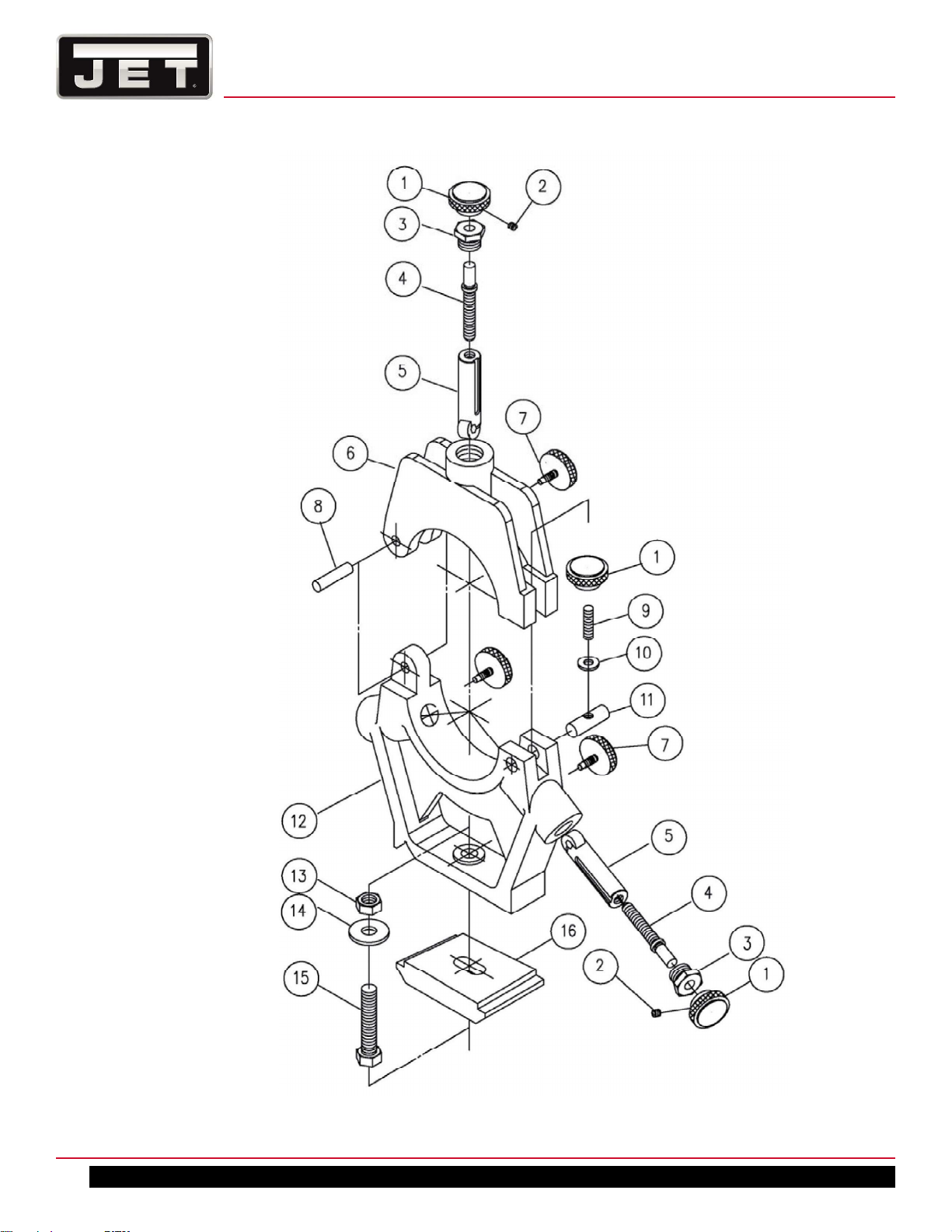
TOOLPOST ASSEMBLY
38
1340-1440 Lathe
Page 39

TOOLPOST ASSEMBLY PARTS LIST
Index No. Part No. Description Size Qty.
1 E1340VS-E01 Screw Ø12.7*65L 8
2 E1340VS-E02 Toolpost 90*90*72h 1
3 E1340VS-E03 Top Slide 215l*90W*38h 1
4 E1340VS-E04 Handle 3/8 in. 1
E1340VS-E04A Handle Assy (including #4&5) 1
5 E1340VS-E05 Handle Ø1/2" *107L 1
6 E1340VS-E06 Handle Ø32*48L 5/8"~11NCTAP 1
7 E1340VS-E07 Washer Ø35*Ø16*12h 1
8 E1340VS-E08 Bolt Ø10*111L 1
9 E1340VS-E09 Pad Ø3/5"*15L 1
10 E1340VS-E10 Spring 3/8in *20mm. 1
11 E1340VS-E11 Nut Ø90*50W*18h 1
12 E1340VS-E12 Oil 5/16 in. 1
13 E1340VS-E13 Handle 1
14 E1340VS-E14 Pad Ø16*24L 1
15 E1340VS-E15 Nut Ø20*40L 1
16 E1340VS-E16 Screw Ø3/4"*177L 2TPI 1
E1340VS-E15A Nut Assembly (Includes #15-16) 1
17 E1340VS-E17 Key 8*15 mm. 1
18 E1340VS-E18 Keep Ass’y Ø57*Ø17*16W 1
19 TS-1503041 Socket Head Cap Screw M6*16mm 2
20 BB-51103 Thrust NO. 51103 1
21 E1340VS-E21 Index Ring Ø54*Ø40*20 1
22 E1340VS-E22 Handwheel Ø62*Ø17*42L 1
23 E1340VS-E23 Spring 1/4 in.*20mm. 2
24 E1340VS-E24 Ball Steel 1/4 in. dia. 2
25 E1340VS-E25 Three Ball Handle 1
26 TS-1503071 Socket Head Cap Screw M6*30mm 1
27 E1340VS-E27 Swiver Slide 35H 1
27 E1440VS-E27 Swiver Slide 44H 1
28 TS-1504031 Socket Head Cap Screw M8*16mm 2
29 E1340VS-E29 Gib Screw Ø5/8"*30L 2
30 TS-1523051 Set Screw M6*16mm 1
31 E1340VS-E31 Gib 112*20*225 1
32 E1340VS-E32 Pin 1
E-1340VS | E-1440VS
39
Page 40

TAILSTOCK ASSEMBLY
40
1340-1440 Lathe
Page 41

TAILSTOCK ASSEMBLY PARTS LIST
Index No. Part No. Description Size Qty.
1 E1340VS-F01 Nut 43L*30W*33h 1
2 TS-1503041 Socket Head Cap Screw M6*16mm 5
3 E1340VS-F03 Screw Ø22*208L 10TPI 1
E1340VS-F01A Nut Assembly (Includes #1-3) 1
4 E1340VS-F04 Key 4*20 mm. 1
5 BB-51103 Thrust NO. 51103 1
6 E1340VS-F06 Keep Ø70*Ø17*17W Ø32*9 1
7 E1340VS-F07 Index Ring Ø73*Ø45*20W 1
8 E1340VS-F08 Barrel Ø45*210L Ø20 1
9 E1340VS-F09 Casting 230L*136W*174.5h 1
10 E1340VS-F10 Spring 1/4 in.*20mm. 2
11 E1340VS-F11 Ball Steel 1/4 in. dia. 2
12 E1340VS-F12 Handle Ø22*100L 2
13 E1340VS-F13 Pulg Ø35*15L M6TAP 4
14 TS-1523071 Set Screw M6*25mm 1
15 E1340VS-F15 Handle Ø140*68h. 1
16 E1340VS-F16 Oil 5/16 in. 2
17 E1340VS-F17 Pad Ø1/2"*16.7L 1
18 TS-1523051 Set Screw M6*16mm 2
19 TS-1540041 Nut M6 2
20 E1340VS-F20 Handle 3/8 in. 1
21 E1340VS-F21 Handle Ø1/2" *107L 3
E1340VS-F21A Handle Assy (including #20&21) 1
22 E1340VS-F22 Shaft Ø25*97L 1
23 E1340VS-F23 Pin 5*12 mm. 2
24 E1340VS-F24 Handle Ø1/2"*190L 1
E1340VS-F24A Handle Assy (including #20&24) 1
25 E1340VS-F25 Shaft Ø25*120L 1
26 E1340VS-F26 Pirot Block 36L*20W*57h 1
27 E1340VS-F27 Gib 8*10*136 1
28 E1340VS-F28 Gib Screw Ø5/8"*30L 2
29 TS-1504101 Socket Head Cap Screw M8*50mm 2
30 E1340VS-F30 Base 185L*136W*53h 1
30 E1440VS-F30 Base 185L*136W*66h 1
31 E1340VS-F31 Clamp Plate 106L*70W*22h 1
32 TS-0680061 Washer 1/2 in. 1
33 E1340VS-F33 Cap Screw 1/2*2-5/8 in. 1
E-1340VS | E-1440VS
41
Page 42

BED ASSEMBLY
42
1340-1440 Lathe
Page 43

BED ASSEMBLY PARTS LIST
Index No. Part No. Description Size Qty.
1 E1340VS-G01 Bed 206W*280.5h*1420L 1
2 E1340VS-G02 Gap Piece 206W*240L*90.5h 1
3 E1340VS-G03 Taper Pin #6x50mm 2
4 TS-1505051 Socket Head Cap Screw M10*35mm 4
5 TS-0070041 Cap Screw 1/2*1-3/4 in. 6
6 E1340VS-G06 Rack 16*19 1050L 1
7 TS-1503051 Socket Head Cap Screw M6*20mm 8
8 E1340VS-G08 Pin 5*25 mm. 5
9 E1340VS-G09 Pin 5*35 mm. 3
10 E1340VS-G10 Leadscrew Ø7/8" 1338L 8TPI 1
11 E1340VS-G11 Bracket 50*50*195L 1
12 E1340VS-G12 Oil 5/16 in. 1
13 TS-1504101 Socket Head Cap Screw M8*50mm 2
14 E1340VS-G14 Pin 5*60 mm. 2
15 E1340VS-G15 Pin 5*40 mm. 1
16 E1340VS-G16 Clutch Ø42*Ø19*38.4L 1
17 E1340VS-G17 Ball Steel 1/4 in. dia. 3
18 E1340VS-G18 Spring 1/4 in.*35mm. 3
19 TS-1524011 Set Screw M8*8mm 7
20 E1340VS-G20 Feed Shaft Ø3/4" 1350L 1
21 E1340VS-G21 Bearing Cover Ø39*Ø19.05*21W 1
22 BB-51104 Thrust NO. 51104 1
23 E1340VS-G23 Third-Rod Shaft Ø3/4" 1710L 1
24 E1340VS-G24 Perspex Cover 114L*80W*1.0t 1
25 E1340VS-G25 Screw 1/4*3/8 in. 28
26 E1340VS-G26 Collar Ø44*Ø19.05*30W 1
27 TS-1503031 Socket Head Cap Screw M6*12mm 3
28 E1340VS-G28 Box 115L*80W*48h 1
29 E1340VS-G29 Collar Ø38*Ø19.05*12W 1
30 E1340VS-G30 Key 5*60 mm. 1
31 E1340VS-G31 Pin 3*8 mm. 2
32 E1340VS-G32 Sleeve Ø38*Ø19.05*60L 1
33 E1340VS-G33 Spring 5/8in *21mm. 1
34 E1340VS-G34 Pin Ø6.3*19L 1
35 E1340VS-G35 Bracket 1
36 TS-1503041 Socket Head Cap Screw M6*16mm 4
37 E1340VS-G37 Fork Ø51*20 1
38 TS-1523051 Set Screw M6*16mm 1
E-1340VS | E-1440VS
43
Page 44

Index No. Part No. Description Size Qty.
39 TS-1540041 Nut M6 1
40 E1340VS-G40 Pin 3*20 mm. 1
41 E1340VS-G41 Handle Ø3/8"*220L 1
E1340VS-G41A Handle Assy (including #41&42) 1
42 E1340VS-G42 Handle 3/8 in. 1
43 E1340VS-G43 Box 1
44 E1340VS-G44 Screw 3/16*3/8 in. 2
45 E1340VS-G45 Electric Plate 1
46 E1340VS-G46 Coolant Selecting Switch 1
47 E1340VS-G47 Jogging Push Bottom Switch 1
48 E1340VS-G48 Emergency Stop Switch 1
49 E1340VS-G49 Variable Speed Selector 1
128 E1340VS-G128 Spring 1/4 in.*30mm. 1
44
1340-1440 Lathe
Page 45

CABINET AND PANEL ASSEMBLY
E-1340VS | E-1440VS
45
Page 46

CABINET AND PANEL ASSEMBLY PARTS LIST
Index No. Part No. Description Size Qty.
50 E1340VS-G50 Electric Box Door 1
51 E1340VS-G51 Electric Box 1
52 E1340VS-G52 Electric Plate 1
53 E1340VS-G53 RPM Speed Meter 1
54 E1340VS-G54 Pilot Light 1
55 E1340VS-G55 Warning Plate 1
56 E1340VS-G56 Power Switch 1
57 E1340VS-G57 Splash Guard 1
58 E1340VS-G58 Work Lamp AC24V 9W 0.5m/500Lux 1
59 E1340VS-G59 Pipe 115mm 1
60 E1340VS-G60 Guard 1
61 TS-0207041 Cap Screw 1/4*3/4in. 1
62 E1340VS-G62 Tray 1
63 E1340VS-G63 Chip Tray 1
64 E1340VS-G64 Cover 1
65 TS-0561031 Nut 3/8 in. 3
66 TS-0680061 Washer 1/2 in. 1
67 TS-0561051 Nut 1/2 in. 3
68 E1340VS-G68 Screw 1
69 E1340VS-G69 Platform 1
70 E1340VS-G70 Shaft 1
71 E1340VS-G71 Stand 1
72 E1340VS-G72 Spring 1
73 E1340VS-G73 Cover 1
74 E1340VS-G74 Pulley 1
75 E1340VS-G75 Circlip E-6 mm. 1
76 E1340VS-G76 Fulcrum 1
77 E1340VS-G77 Collar 1
78 E1340VS-G78 Lever 1
79 TS-0100041 Cap Screw 1/2*1-1/4 in. 6
80 E1340VS-G80 Shaft 1
81 E1340VS-G81 Pin 5*30 mm. 4
82 E1340VS-G82 Stand 1
83 E1340VS-G83 Cover 1
84 E1340VS-G84 Pump 1
85 E1340VS-G85 Tank 1
86 E1340VS-G86 Tray 1
87 E1340VS-G87 Bracket 2
88 E1340VS-G88 Front Plate 1
89 E1340VS-G89 Pedal 1
90 E1340VS-G90 Main Motor 3HP 60HZ 220/440V 1
129 E1340VS-G129 Shaft 1
46
1340-1440 Lathe
Page 47

END GEAR ASSEMBLY
E-1340VS | E-1440VS
47
Page 48

END GEAR ASSEMBLY PARTS LIST
Index No. Part No. Description Size Qty.
27 TS-1503031 Socket Head Cap Screw M6*12mm 2
65 TS-0561031 Nut 3/8 in. 2
67 TS-0561051 Nut 1/2 in. 2
91 E1340VS-G91 Washer Ø25*Ø1/4"*3t 2
92 E1340VS-G92 Gear 1.25M 30T 1
93 E1340VS-G93 Swing Frame 1
94 E1340VS-G94 Key 5*15 mm. 2
95 E1340VS-G95 Washer Ø25*Ø3/5"*5t 1
96 BB-6003Z Bearing NO. 6003Z 2
97 E1340VS-G97 Circlip R-35 mm. 2
98 E1340VS-G98 Gear 1.25M 120T/127T 1
99 E1340VS-G99 Shaft Collar Ø25*Ø3/8"*29L 1
100 E1340VS-G100 Shaft Ø25*65L 1
101 E1340VS-G101 Shaft 1
102 E1340VS-G102 Washer Ø25*1/2"*3t 1
103 E1340VS-G103 Gear 1.25M 60T 1
104 E1340VS-G104 Stud Ø3/8"*105L 1
105 E1340VS-G105 Nut Ø*16W 3/8~16NC 1
106 E1340VS-G106 End Cover 1
106 E1440VS-G106 End Cover 1
107 E1340VS-G107 Cap Screw 1/4*1-1/4 in. 1
108 E1340VS-G108 Nut 1/4 in. 1
109 E1340VS-G109 Gear 1.25M 50T 2
110 E1340VS-G110 Gear 1.25M 45T 1
111 E1340VS-G111 Gear 1.25M 40T 2
48
1340-1440 Lathe
Page 49

CHUCK SAFETY GUARD ASSEMBLY
E-1340VS | E-1440VS
49
Page 50

CHUCK SAFETY GUARD ASSEMBLY PARTS LIST
Index No. Part No. Description Size Qty.
36 TS-1503041 Socket Head Cap Screw M6*16mm 2
112 E1340VS-G112 Cam 1
113 TS-1523021 Set Screw M6*8mm 3
114 E1340VS-G114 Keep Ass’y 1
115 TS-1503021 Socket Head Cap Screw M6×10mm 1
116 E1340VS-G116 Collar 1
117 E1340VS-G117 Cam 1
119 E1340VS-G119 Shaft 1
120 E1340VS-G120 Collar 1
121 E1340VS-G121 Chuck Guard 1
E1340VS-CSGA
122 E1340VS-G122 Handle PVC 1
123 TS-1505031 Socket Head Cap Screw M10×25mm 1
124 E1340VS-G124 Screw 3/16×1/4 in 18
125 E1340VS-G125 Nut 3/16 in 18
126 E1340VS-G126 Window 3Tx193x343mm 1
127 E1340VS-G127 Window 3Tx193x230mm 1
Chuck Safety Guard ass’y w/ limit
switch
(option) 1
50
1340-1440 Lathe
Page 51

COOLANT PUMP ASSEMBLY
E-1340VS | E-1440VS
51
Page 52

COOLANT PUMP ASSEMBLY PARTS LIST
Index No. Part No. Description Size Qty.
84 E1340VS-G84 Pump 1
130 E1340VS-G130 Nipple 1
131 E1340VS-G131 Flexible Hose 1
132 E1340VS-G132 Nipple 1
133 E1340VS-G133 Tube 1
134 E1340VS-G134 Bracket 1
135 E1340VS-G135 Value Gate 1
136 E1340VS-G136 Spraying Pipe 1
52
1340-1440 Lathe
Page 53

DIAL INDICATOR ASSEMBLY
DIAL INDICATOR ASSEMBLY PARTS LIST
Index No. Part No. Description Size Qty.
40 E1340VS-G40 Pin 3*20 mm. 1
137 E1340VS-G137 Plate 1
138 E1340VS-G138 Dog Ø60*Ø19.05*15W 1
139 E1340VS-G139 Pin 3*12 mm. 1
140 E1340VS-G140 Nail 2 mm. 1
141 E1340VS-G141 Guard 75*59*45 1
142 TS-1503111 Socket Head Cap Screw M6*50mm 1
143 E1340VS-G143 Shaft Ø9.5*81L 1
144 E1340VS-G144 Gear Ø34Ø9.5*17L 1
145 E1340VS-TP Threading Plate 1
E-1340VS | E-1440VS
53
Page 54

CHUCK ASSEMBLY & PARTS LIST
Index No. Part No. Description Size Qty.
7 TS-1503051 Socket Head Cap Screw M6*20mm 3
145 E1340VS-SK6 Chuck 6" 1
146 E1340VS-G146 Backplate 6" 1
147 E1340VS-G147 Stud D1-4 3
CHUCK KEY BRACKET ASSEMBLY & PARTS LIST
Index No. Parts No. Description Size Qty.
1 TS-1504111 Socket Head Cap Screw M8x55mm 2
2 EVS1440B-CKB Chuck Key Bracket 1
54
1340-1440 Lathe
Page 55

FACE PLATE & PARTS LIST
Index No. Parts No. Description Size Qty.
1 E1440VS-FP02 Face Plate 12” Ø300x40H 1
3 EBL1236VS-G137 Stud D1-4 3
4 TS-1503051 Socket Head Cap Screw M6×20mm 3
E-1340VS | E-1440VS
55
Page 56

CONTROL PLATE ASSEMBLY
56
1340-1440 Lathe
Page 57

CONTROL PLATE ASSEMBLY PARTS LIST
Index No. Part No. Description Size Qty.
1 E1340VS-H01 Plate 1
2 E1340VS-H02 Track 1
3 E1340VS-H03 Fuse Box 4
4 E1340VS-H04 Fuse 5A 4
5 E1340VS-H05 Relay Socket for Magnetic brake 1
6 E1340VS-H06 Relay MY4N-J Ac24v 4
7 E1340VS-H07 Inverter VFD-B Ac240v 5HP 1
8 E1340VS-H08 Trunking 1
9 E1340VS-H09 Track 1
10 E1340VS-H10 Relay Socket 1
11 E1340VS-H11 Relay Socket 1
12 E1340VS-H12 Trunking 1
13 E1340VS-H13 Trunking 1
14 E1340VS-H14 Control Circuit Transformer 120VC Ac24v(5A) 1
15 E1340VS-H15 Track 1
16 E1340VS-H16 Bridge Rectifier 1
17 E1340VS-H17 Relay Socket 1
18 E1340VS-H18 Fuse Boxes 1
19 E1340VS-H19 Fuse 30A 3
20 E1340VS-H20 Magnetic Contactor CU-11 Ac24v (3A1b) 1
21 E1340VS-H21 Thermal Overload Relay RHU-10K1 0.45~0.63A 1
22 E1340VS-H22 Trunking 1
23 E1340VS-H23 Earthing Terminal Blocks 1
24 E1340VS-H24 Track 1
25 E1340VS-H25 Terminal Blocks 1
26 E1340VS-H26 Base 1
27 E1340VS-H27 Main Power Switch 690VAC 25A 1
E-1340VS | E-1440VS
57
Page 58

TAPER ATTACHMENT ASSEMBLY (OPTIONAL)
58
1340-1440 Lathe
Page 59

TAPER ATTACHMENT ASSEMBLY (OPTIONAL) PARTS LIST
Index No. Part No. Description Size Qty.
1 BB-51101 Thrust Bearing 51101 2
2 E1440VS-J02 Feed Block 52x20x35 1
3 E1440VS-J03 Yoke 60x42x41.5 1
4 E1440VS-J04 Socket Head Cap Screw M5x65MM 2
5 E1440VS-J05 Base 175x180x85 1
6 E1440VS-J06 Cover 170x63x1.2 1
7 E1440VS-J07 Lead Screw Ø5/8"x405L 1
8 E1440VS-J08 Shaft Ø12x50L 1
9 TS-1524011 Set Screw M8x8mm 1
10 E1440VS-J10 Gib 130x18.86(10.2)x15 1
11 TS-1503061 Socket Head Cap Screw M6x25mm 4
12 TS-1523061 Set Screw M6x20mm 4
13 E1440VS-J13 Bracket 159x60x40 1
14 TS-1504081 Socket Head Cap Screw M8x40mm 1
15 E1440VS-J15 Angle Plate 128x25x1.2 1
16 E1440VS-J16 Gib Screw 2
17 TS-1503071 Socket Head Cap Screw M6x30mm 1
18 E1440VS-J18 Gib 110x7.27x5.57 1
19 E1440VS-J19 Pivot Pin 1
20 E1440VS-J20 Slide Bar (with riveted scales) 420x40x15 1
21 TS-1503081 Socket Head Cap Screw M6x35mm 1
22 E1440VS-J22 Angle Plate 126x25x1.2 1
23 TS-2236181 Socket Head Cap Screw M6x18mm 1
24 E1440VS-J24 Strip 80x31x13 1
25 TS-1503031 Socket Head Cap Screw M6x12mm 2
26 E1440VS-J26 Base 460x130x18 1
27 E1440VS-J27 Screw Ø3/8"(Ø9.525)x105L 1
28 E1440VS-J28 Nut Ø22x22L 1
29 E1440VS-J29 Screw Block 19x19x22 1
30 E1440VS-J30 Knurled Nut Ø28(Ø20)x19L 1
31 E1440VS-J31 Pin 3x15mm 1
32 E1440VS-J32 Pivot Ø3/4"x65L 1
34 E1440VS-J33 Rod Ø1/2"x300L 1
35 TS-1503041 Socket Head Cap Screw M6x16mm 1
36 E1440VS-J35 Block 25x25x10 1
37 TAK1340A-5 Flat Head Screw M5x8 6
38 TS-1504061 Hex Socket Cap Screw M8x30 2
39 TS-1550061 Flat Washer M8 2
40 E1440VS-J39 Slide Block 1
41 TS-1540041 Hex Nut M6 1
892035 Taper Assembly (#1 thru 41) 1
E-1340VS | E-1440VS
59
Page 60

COLLET CLOSER ASSEMBLY (OPTIONAL)
60
1340-1440 Lathe
Page 61

COLLET CLOSER ASSEMBLY (OPTIONAL) PARTS LIST
Index No. Part No. Description Size Qty.
1 C51064006 Sleeve Coupling 1
2 C52302004 Fixed Seat (Length) 1
3 C53004118 Sleeve #5 1
4 C54002038 Coupling 1
5 C54004047 Arbor 1
6 C54006001 Buckle 3
7 C54008007 Buckling Plate 1
8 C54012019 Outward Flange 1
9 C54014002 Bearing Shaft 1
10 C54016011 Bearing Stand 1
11 C54018020 Collar 1
12 C54020023 Bearing Body 1
13 C54021000 Set Screw 2
14 C54025015 Coupling 2
15 C54026005 Special Pin 2
16 C54027202 Stud 273L 1
17 C54029208 Lever Shaft 205L 1
18 C554920 Draw Bar 492L 1
19 BB-6208ZZ Ball Bearing 6208ZZ 1
20 SB-6MM Steel Ball Ø6.0 1
21 5510484 Spring Pin 5 x 20L 1
22 GB050254 Spring Pin 1/4" x1-1/2L 3
23 GC020101 Retaining Ring (external) 32 1
24 GD020596 Grip 1/2" 1
25 GE040176 Spring 1
26 TS-1501021 Hex Socket Cap Screw M4 x 8L 3
27 TS-1523031 Set Screw M6 x10L 3
28 GF030823 Locking Nut AN08 1
29 GF041946 Hex Nut 5/16” 2
30 GF041959 Hex Nut 1/2” 3
892036 5C Collet Closer Assembly (#1 thru 30) 1
E-1340VS | E-1440VS
61
Page 62
STEADY REST ASSEMBLY
62
1340-1440 Lathe
Page 63

STEADY REST ASSEMBLY PARTS LIST
Index No. Parts No. Description Size Qty.
1 E1440VS-FR01 Nut Ø20xØ24x25L 4
2 TS-1523011 Set Screw M6*6mm 3
3 E1440VS-FR03 Screw Ø23x17L 3
4 E1440VS-FR04 Set Screw Ø9.5x77L 3
E1440VS-FR01A Nut Assembly (includes #1~4) 3
5 E1440VS-FR05 Bearing Shaft Ø18.8(Ø24)x83L 3
6 E1440VS-SR06 Arm 168x40x130 mm 1
7 E1440VS-FR07 Set Screw Ø20xØ4.5x30L 3
8 E1440VS-SR08 Shaft Ø8x40L 1
9 E1440VS-SR09 Set Screw M8*55mm 1
10 TS-0732061 Washer 3/8 in 1
11 E1440VS-SR11 Pin Ø12.7x40L 1
12 E1340VS-SR12 Base 13” 246x40x194 1
E1440VS-SR12 Base 14” 247x40x194 1
13 TS-0561051 Hex Nut 1/2-13 in 1
14 TS-0680061 Flat Washer 1/2 in. 1
15 TS-0070071 Hex Cap Screw 12-13 x 2-1/2 in. 1
16 E1340VS-F31 Clamp Plate 106L*70W*22h 1
E1340VS-SRA Steady Rest Assembly for E-1340VS (#1~16)
E1440VS-SRA Steady Rest Assembly for E-1440VS (#1~16)
E-1340VS | E-1440VS
63
Page 64

FOLLOW REST ASSEMBLY
64
1340-1440 Lathe
Page 65

FOLLOW REST ASSEMBLY PARTS LIST
Index No. Parts No. Description Size Qty.
1 E1440VS-FR01 Nut Ø20xØ24x25L 2
2 TS-1523011 Set Screw M6*6mm 2
3 E1440VS-FR03 Screw Ø23x17L 2
4 E1440VS-FR04 Set Screw Ø9.5x77L 2
E1440VS-FR01A Nut Assembly (includes #1~4) 2
5 E1440VS-FR05 Bearing Shaft Ø18.8(Ø24)x83L 2
6 E1340VS-FR06 Follow Rest (for 1340VS) 174x40x280 mm 1
E1440VS-FR06 Follow Rest (for 1440VS) 175x40x280 mm 1
7 E1440VS-FR07 Set Screw Ø20(Ø4.5)x30L 2
8 TS-1490081 Socket Head Cap Screw M8*45mm 2
E1340VS-FRA Follow Rest Assembly for E-1340VS (#1~8)
E1440VS-FRA Follow Rest Assembly for E-1440VS (#1~8)
E-1340VS | E-1440VS
65
Page 66

11.0 WIRING DIAGRAMS
66
1340-1440 Lathe
Page 67

E-1340VS | E-1440VS
67
Page 68

NOTES
68
1340-1440 Lathe
 Loading...