


This .pdf document is bookmarked
Operating Instructions and Parts Manual
Portable Woodworking Dust Collector
Model DC-500P
JET
427 New Sanford Road
LaVergne, Tennessee 37086 Part No. M-717500
Ph.: 800-274-6848 Edition 1 06/2018
www.jettools.com Copyright © 2018 JET

1.0 IMPORTANT SAFETY
INSTRUCTIONS
When using an electrical appliance, basic
precautions should always be followed, including
the following:
READ ALL INSTRUCTIONS BEFORE USING THIS
DUST COLLECTOR.
WARNING – To reduce the risk of fire,
electric shock, or injury:
1. Read and understand entire owner’s manual
before attempting assembly or operation of this
dust collector.
2. Read and understand the warnings posted on
the machine and in this manual.
3. Replace warning labels if they become
obscured or removed.
4. This dust collector is designed and intended for
use by properly trained and experienced
personnel only. If you are not familiar with the
proper and safe operation of a dust collector, do
not use until proper training and knowledge
have been obtained.
5. Do not use this dust c ollector for other than its
intended use. If used for other purposes, JET
disclaims any real or implied warranty and holds
itself harmless from any injury that may result
from that use.
6. Always wear approved safety glasses/face
shield while using this dust collector. Everyday
eyeglasses only have impact resistant lenses;
they are not safety glasses.
7. Keep hair, loose clothing, fingers, and all parts
of body away from openings and moving parts.
8. Wear hearing protection (plugs or muffs) during
extended periods of operation.
9. CALIFORNIA PROPOSITION 65 WARNING:
This product contains chemicals known to the
State of California to cause cancer, or birth
defects or other reproductive harm.
10. WARNING: Drilling, sawing, sanding or
machining wood products generates wood dust
and other substances known to the State of
California to cause cancer. Avoid inhaling dust
generated from wood products or use a dust
mask or other safeguards to avoid inhaling dust
generated from wood products.
11. Wood products emit chemicals known to the
State of California to cause birth defects or
other reproductive harm. (California Health and
Safety Code Section 25249.6)
12. Do not operate this machine while tired or under
the influence of drugs, alcohol or any
medication.
13. Make certain the switch is in the OFF position
before connecting the machine to the power
supply. Turn off all controls before unplugging.
14. Make certain the machine is properly grounded.
Connect to a properly grounded outlet only. See
Grounding instructions.
15. Make all machine adjustments or maintenance
with the machine unplugged from the power
source.
16. Remove adjusting keys and wrenches. Form a
habit of checking to see that keys and adjusting
wrenches are removed from the machine
before turning it on.
17. Keep safety guards in place at all times when
the machine is in use. If removed for
maintenance purposes, use extreme caution
and replace the guards immediately after
maintenance is complete.
18. Check damaged parts. Before further use of the
machine, a guard or other part that is damaged
should be carefully checked to determine that it
will operate properly and perform its intended
function. Check for alignment of moving parts,
binding of moving parts, breakage of parts,
mounting and any other conditions that may
affect its operation. A guard or other part that is
damaged should be properly repaired or
replaced.
19. Provide for adequate space surrounding work
area and non-glare, overhead lighting.
20. Keep the floor around the machine clean and
free of scrap material, oil and grease.
21. Keep visitors a safe distance from the work
area. Keep children away.
22. Make your workshop child proof with padlocks,
master switches or by removing starter keys.
23. Give your work undivided attention. Looking
around, carrying on a conversation and “horseplay” are careless acts that can result in serious
injury.
24. The dust collector is intended for indoor use. To
reduce the risk of electric shock, do not use
outdoors or on wet surfaces.

25. Do not use this dust collector for anything
except wood dust. Materials such as liquids,
metal shavings, metal dust, screws, glass,
plastic or rock can cause sparks and/or damage
when coming into contact with any part of the
dust collector.
26. Do not use to pick up anything that is burning or
smoking, such as cigarettes, matches or hot
ashes.
27. Do not use to pick up flammable or combustible
liquids such as gasoline, or use in areas where
they may be present.
28. Do not pull or carry by cord, use cord as a
handle, close a door on cord, or pull cord
around sharp edges or corners. Do not run dust
collector over cord. Keep cord away from
heated surfaces.
29. Do not use this dust collector with a damaged
cord or plug. If the unit is not working as it
should, has been dropped, damaged, left
outdoors, or dropped into water, return it to a
service center.
30. Do not unplug by pulling on cord. To unplug,
grasp the plug, not the cord.
31. Do not use without dust bag and/or filters in
place.
32. Do not handle plug or machine with wet hands.
Familiarize yourself with the following safety notices used in this manual:
33. Do not put any objects into the openings. Do not
use with any opening blocked; keep free of
dust, lint, hair, and anything that may reduce air
flow.
34. Keep hands and fingers away from inlet and
exhaust ports during operation.
35. Do not operate without hose connected to the
inlet. Place cap on unused inlet port. Hazardous
moving parts inside.
36. Use recommended accessories; improper
accessories may be hazardous.
37. Maintain tools with care. Follow instructions for
lubricating and changing accessories.
38. Turn off machine and disconnect from power
before cleaning. Use a brush or compressed air
to remove chips or debris; do not use bare
hands.
39. Do not leave the machine when it is plugged in.
Unplug from outlet when not in use and before
servicing.
40. Do not stand on the machine. Serious injury
could occur if the machine tips over.
41. The dust collector is intended for household
(non-industrial) use.
This means that if precautions are not heeded, it may result in minor injury and/or possible
machine damage.
This means that if precautions are not heeded, it may result in serious, or possibly even fatal,
injury.
SAVE THESE INSTRUCTIONS
2.0 About this manual
This manual is provided by JET, covering the safe operation and maintenance procedures for a JET Model DC500P Dust Collector. This manual contains instructions on installation, safety precautions, general operating
procedures, maintenance instructions and parts breakdown. Your machine has been designed and constructed
to provide consistent, long-term operation if used in accordance with the instructions set forth in this document.
This manual is not intended to be a guide to dust removal strategies, installation of larger collection systems, or
the use of optional dust collecting accessories. Additional knowledge may be obtained from experienced users,
trade articles or website forums. Whatever accepted methods are used, always make personal safety a priority.
If there are questions or comments about this product, please contact your local supplier or JET. JET can also
be reached at our web site: www.jettools.com.
Retain this manual for future reference. If the machine transfers ownership, the manual should accompany it.
Register your product using the mail-in card provided, or register online:
http://www.jettools.com/us/en/service-and-support/product-registration/
3

3.0 Table of contents
Section Page
1.0 IMPORTANT SAFETY INSTRUCTIONS ....................................................................................................... 2
2.0 About this manual .......................................................................................................................................... 3
3.0 Table of contents ............................................................................................................................................ 4
4.0 Specifications ................................................................................................................................................. 5
5.0 Setup and assembly ....................................................................................................................................... 6
5.1 Unpacking .................................................................................................................................................. 6
5.2 Shipping contents ....................................................................................................................................... 6
5.3 Tools required for assembly ....................................................................................................................... 6
5.4 Assembly .................................................................................................................................................... 7
5.5 Wall mounting ............................................................................................................................................. 8
6.0 Electrical connections .................................................................................................................................... 8
6.1 GROUNDING INSTRUCTIONS ................................................................................................................. 8
6.2 Voltage conversion ..................................................................................................................................... 9
6.3 Extension cords .......................................................................................................................................... 9
6.4 Grounding wire information ........................................................................................................................ 9
7.0 Operation ..................................................................................................................................................... 10
7.1 Switch key ................................................................................................................................................. 10
8.0 User-maintenance ........................................................................................................................................ 10
8.1 Additional servicing .................................................................................................................................. 10
9.0 Troubleshooting DC-500P Dust Collector .................................................................................................... 11
10.0 Replacement Parts ..................................................................................................................................... 12
10.1.1 DC-500P Portable Dust Collector – Exploded View ............................................................................ 12
10.1.2 DC-500P Portable Dust Collector – Parts List ..................................................................................... 13
11.0 Electrical Connections for DC-500P ........................................................................................................... 14
11.1 Electrical Connections for 3/4HP, 1PH, 115V only ................................................................................. 14
11.2 Electrical Connections for 3/4HP, 1PH, 230V only ................................................................................. 14
12.0 Warranty and service ................................................................................................................................. 15
The specifications in this manual were current at time of publication, but because of our policy of continuous
improvement, JET reserves the right to change specifications at any time and without prior notice, without incurring
obligations.
4

4.0 Specifications
Table 1
Model number
Stock number 717500
Motor and electrical
Motor type totally enclosed fan cooled, induction, ca pac itor start
Horsepower 3/4HP (0.55 kW)
Phase 1 PH
Voltage 115/230 V
Cycle 60 Hz
Listed FLA (full load amps) 7.5/3.75 A
Starting amps 24/15 A
Running amps (no load) 6/3.1 A
Running capacitor
On/off switch HY7 Toggle with removable safety key
Motor speed (no load) 3450 RPM
Power cord 16AWG x 3C, 6-1/2 ft.
Power plug included 5-15P
Recommended circuit size 1 15 A
Sound emission 2 78 dB
Capacities
Dust inlet outside diameter 3-15/16 in. (100 mm)
Hose diameter 4 in. (102 mm)
Maximum nominal air flow 500 CFM (14.6 m3/min)
Air veloci ty at 4 in. 6690 FPM (34 m/s)
Maximum static pressure loss (WC) 5.8 inH2O (147.3 mmH2O)
Impeller
Type radial fin
Diameter 9 in. (228.6 mm)
Fin thickness 14 ga. (2mm)
Material steel
Collection bag
Bag material cloth, 5 micron
Bag size (Dia. x L), when inflated 16 x 24 in.
Bag capacity 4.7 cu. ft. (0.13 CBM)
Main materials
Base sheet metal
Body/housing sheet metal
Dust funnel plastic
Dust hose PVC
Paint finish powder coat
Dimensions
Approx. overall dimensions, assembled (LxWxH) 24 x 16 x 46 in. (610 x 407 x 1169 mm)
Shipping carton dimensions (LxWxH) 19 x 16.5 x 22 in. (480 x 420 x 560 mm)
Weights
Net weight 48 lbs. (22 kg)
Shipping weight 59.5 lbs. (27 kg)
1
Subject to local/national electrical codes. Recommendation based upon dedicated circuit.
2
The specified values are emission levels and are not necessarily to be seen as safe operating levels. As workplace
conditions vary, this information is intended to allow the user to make a better estimation of the hazards and risks
involved only.
L = length, W = width, H = height
DC-500P
30μF 250VAC
5
Read and understand the
entire contents of this manual before attempting
assembly or operation. Failure to comply may
cause serious injury.
5.0 Setup and assembly
5.1 Unpacking
Remove all contents from shipping carton and
compare to the contents list in this manual. If
shipping damage or any part shortages are
identified, contact your distributor. Do not discard
shipping materials until dust collector is assembled
and running satisfactorily.
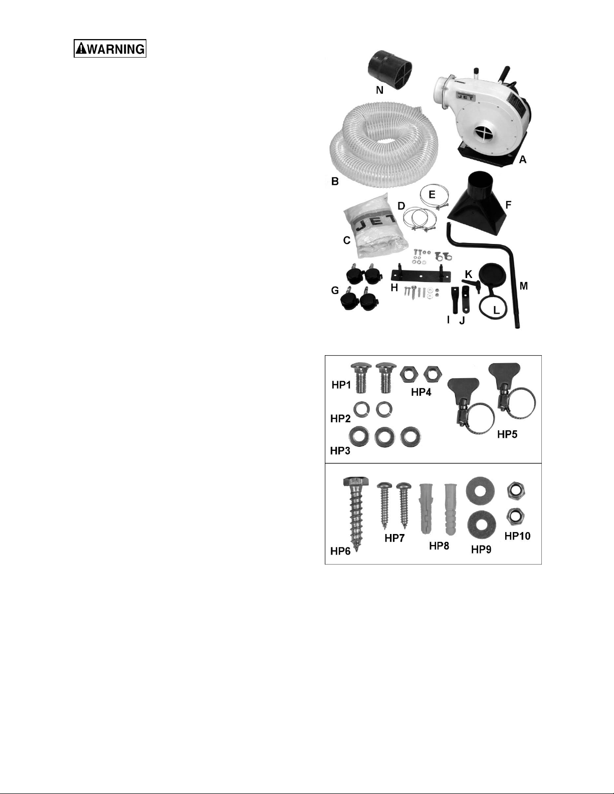
5.2 Shipping contents
Main carton (see Figure 5-1)
1 Main unit – A
1 Flexible hose – B
1 Collection bag – C
2 4” Dia. Wire clamps – D
1 5” Dia. wire clamp – E
1 Dust funnel – F
4 Casters with fasteners – G
1 Wall mount plate – H
1 Upper support tube – I
1 Funnel support bracket – J
1 Locking lever – K
1 Inlet cap – L
1 Lower support tube – M
1 Inlet adaptor – N
Fasteners (see Figure 5-2):
2 Carriage bolts M8x20 – HP1
2 Lock washers 8mm – HP2
3 Flat washers 8mm – HP3
2 Hex nuts M8 – HP4
2 Butterfly clamps – HP5
1 Hex cap lag screw – HP6
2 Phillips self-tapping screws – HP7
2 Screw anchors – HP8
2 Flat washers 8mm – HP9
2 Hex nylon lock nuts M8 – HP10
Figure 5-1
Figure 5-2 (detail of fasteners)
5.3 Tools required for assembly
13mm wrench
17mm wrench
Cross-point (Phillips) screwdriver
Drill with 1/4” and 5/16” bits (if mounting to wall)
6
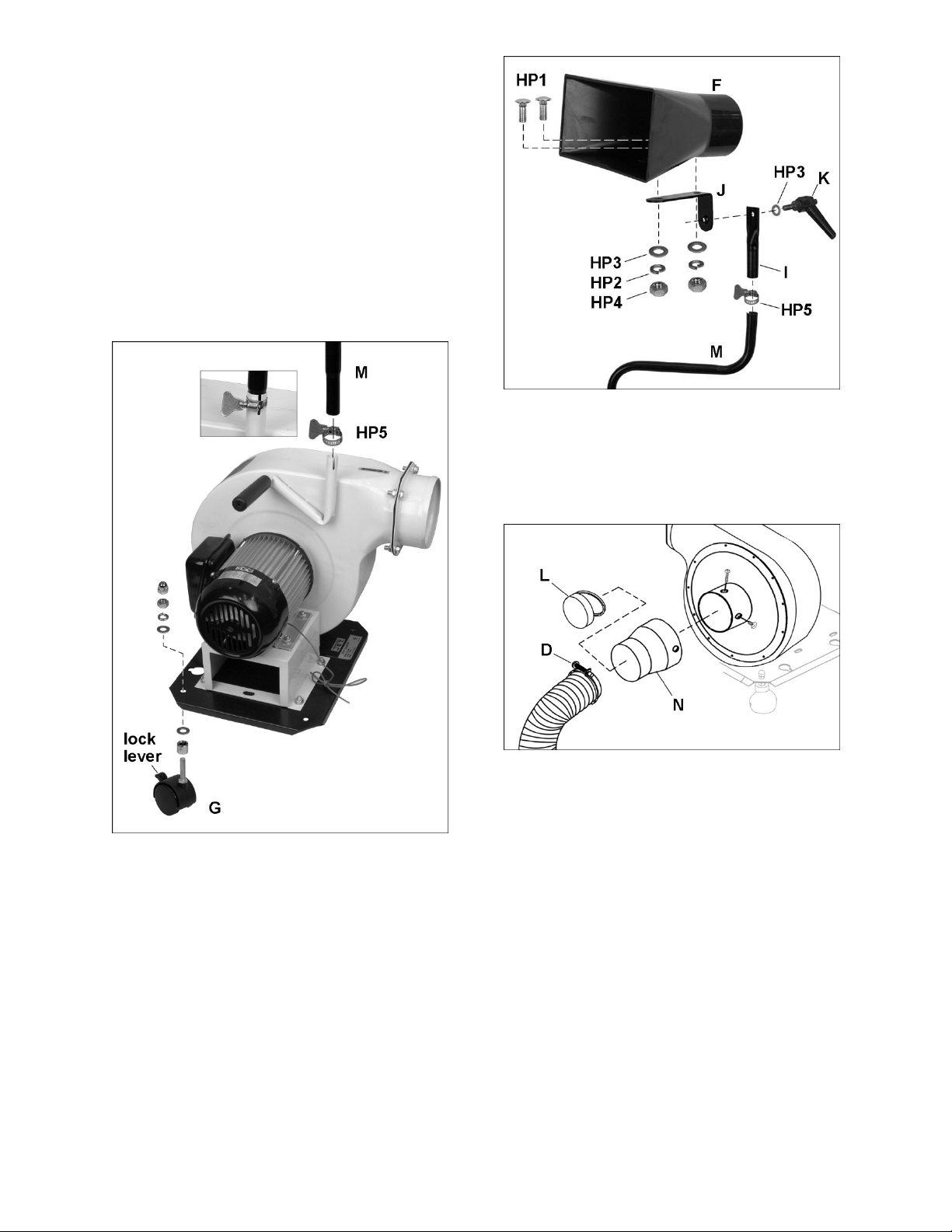
5.4 Assembly
1. Install casters (G, Figure 5-3), to base, using
the fasteners supplied with each caster, in the
order as shown. Tighten the hex nut and cap
nut to secure.
A caster can be locked in position by pushing
down on the adjoining lever. Push up lever to
unlock caster.
NOTE: If Dust Collector will be wall-mounted,
proceed to sect. 5.5, then return to this section
for furt h e r as se mbly.
2. Remove protective cap from tube holder, and
install butterfly clamp (HP5) and lower support
tube (M). Tighten butterfly clamp to secure.
Figure 5-4
5. Push inlet adaptor (N, Figure 5-5) onto inlet port
until the holes align, and secure with the
provided self-tapping screws.
6. Press ring of inlet cap (L) onto adaptor. Press
cap over inlet when inlet is not being used.
Figure 5-3
3. Install upper support tube (I) and secure with
butterfly clamp (HP5). See Figure 5-4.
4. If funnel will be used, mount f unnel bracket (J)
to upper support tube (I) with locking lever (K)
and washer (HP3). Install funnel (F) with
carriage bolts, washers and nuts (HP1/2/3/4).
Figure 5-5
7. Place a 4-inch wire cl amp (D, Figure 5-5) onto
end of hose, and install hose to adaptor.
7
Tighten wire clamp with screwdriver.
8. If using the dust funnel, connect opposite end of
hose to funnel port and secure with 4-inch wire
clamp. Or, connect hose to dust port of
woodworking machine, and secure with wire
clamp.
9. Place 5-inc h diameter wire clamp (E, Figure 5-
6) onto end of collection bag, and slide bag onto
exhaust port. Tighten cloth strap and wire
clamp.

Figure 5-6
5.5 Wall mounting
The dust collector can be suspended from a wall for
operation or storage. The wall mount plate must
be centered over a wall stud.
The wall/supporting structure
must be capable of supporting the weight of the
dust collector and safely absorbing any
vibration from the machine.
1. Position mount plate (H, Figure 8-7) on wall,
make sure it is level, then mark the 3 hole
locations. The center hole must be centered
on a wall stud, and should be approximately 40
inches from floor – this ensures the collection
bag will contact the floor for support.
2. Remove mount plate, and drill 1/4-inch pilot
hole into wall stud at center mark.
3. Drill two 5/32-inch holes in wall at outer hole
locations, and push a screw anchor (HP8) into
each hole.
4. Install mount plate using lag screw (HP6)
through center, and pan head screws (HP7)
through outer holes. Tighten securely.
5. Install flat washer and nylon lock nut (HP9/10)
on the end of each stud.
6. Place the dust collector on the studs, as shown
in Figure 5-8, and tighten the lock nuts enough
to secure the unit to the wall. The casters should
not rotate when the unit is properly secured.
Figure 5-7
Figure 5-8
6.0 Electrical connections
Electrical connections must be
made by a qualified electrician in compliance
with all relevant codes. This machine must be
properly grounded to help prevent electrical
shock and possible fatal injury.
The DC-500P Dust Collector is rated at 115/230V
power, and is pre-wired for 115 volt. The unit comes
with a plug designed for use on a circuit with a
grounded outlet that looks like the one pictured in A,
Figure 6-1.
Before connecting to power source, be sure switch
is in off position.
It is recommended that the dust collector be
connected to a dedicated 15 amp circuit with circuit
breaker or time-delay fuse marked “D”. Local
codes take precedence over recommendations.
6.1 GROUNDING INSTRUCTIONS
1. All Grounded, Cord-connected Tools:
This machine must be grounded. In the event of a
malfunction or breakdown, grounding provides a
path of least resistance for electric current to reduce
the risk of electric shock. This tool is equipped with
an electric cord having an equipment-grounding
conductor and a grounding plug. The plug must be
plugged into a matching outlet that is properly
installed and grounded in accordance with all local
codes and ordinances.
Do not modify the plug provided - if it will not fit the
outlet, have the proper outlet installed by a qualified
electrician.
Improper connection of the equipment-grounding
conductor can result in a risk of electric shock. The
conductor with insulation having an outer surface
that is green with or without yellow stripes is the
equipment-grounding conductor. If repair or
replacement of the electric cord or plug is
8

necessary, do not connect the equipment-grounding
conductor to a live terminal.
Check with a qualified
electrician or service personnel if the grounding
instructions are not completely understood, or if
in doubt as to whether the tool is properly
grounded. Failure to comply may cause ser ious
or fatal injury.
Use only 3-wire extension cords that have 3-prong
grounding plugs and 3-pole receptacles that accept
the tool's plug. Repair or replace damaged or worn
cord immediately.
2. Grounded, cord-connected tools intended for use
on a supply circuit having a nominal rating less than
150 volts:
6.2 Voltage conversion
To convert the dust collector to 230-volt power,
remove motor junction box cover and change the
incoming power leads, according to diagram affixed
inside cover. This diagram is also shown in Figure
6-2. NOTE: In case of discrepancy, diagram on
machine takes precedence.
This tool is intended for use on a circuit that has an
outlet that looks like the one illustrated in A, Figure
6-1. An adapter, shown in B and C, may be used to
connect this plug to a 2-pole receptacle as shown in
B if a properly grounded outlet is not available. The
temporary adapter should be used only until a
properly grounded outlet can be installed by a
qualified electrician. This adapter is not permitted in
Canada. The green-colored rigid ear, lug, and the
like, extending from the adapter must be connected
to a permanent ground such as a properly grounded
outlet box.
Figure 6-1
3. Grounded, cord-connected tools intended for use
on a supply circuit having a nominal rating between
150 - 250 volts, inclusive:
This tool is intended for use on a circuit that has an
outlet that looks like the one illustrated in D, Figure
6-1. The tool has a grounding plug that looks like the
plug illustrated in D. Make sure the tool is connected
to an outlet having the same configuration as the
plug. No adapter is available or should be used with
this tool. If the tool must be reconnected for use on
a different type of electric circuit, the reconnection
should be made by qualified service personnel; and
after reconnection, the tool should comply with all
local codes and ordinances.
Figure 6-2
6.3 Extension cords
The use of extension cords is discouraged; try to
position machines near the power source. If an
extension cord is necessary, make sure it is in good
condition. When using an extension cord, be sure to
use one heavy enough to carry the current your
product will draw. An undersized cord will cause a
drop in line voltage resulting in loss of power and
overheating. Table 1 shows correct size to use
depending on cord length and nameplate ampere
rating. If in doubt, use the next heavier gauge. The
smaller the gauge number, the heavier the cord.
Ampere
Rating
More
Than
0 6 18 16 16 14
6 10 18 16 14 12
10 12 16 16 14 12
12 16 14 12
Not
More
Than
Volts
120
240
AWG
Total length of
cord in feet
25
50
100
50
100
200
Not
Recommended
150
300
Table 1: Extension cord recommendations
6.4 Grounding wire information
A green grounding wire is connected to the base of
the dust collector, and can be used to connect to
dust hose or pipe systems to prevent static
electricity buildup. If you are using the DC-500P as
part of a larger shop system with hoses or PVC pipe,
you should seek further information from website
forums or experienced users as to proper and safe
methods for prevention of static electricity buildup.
9

7.0 Operation
8.0 User-maintenance
7.1 Switch key
To prevent accidental or unauthorized use, turn
machine off and remove safety key (Figure 7-1).
Store key in a safe place, inaccessible to children.
Key must be reinserted to start unit.
Figure 7-1
Turn OFF dust collector and
remove plug from power source before
performing adjustments or maintenance. Failure
to comply may result in serious injury.
No lubrication is required for the dust collector. All
bearings are pre-lubricated and sealed and require
no further attention.
Empty collection bag when full.
The cloth dust collection bag is washable.
Make frequent inspections of motor fan, and blow
out (with low pressure air hose) or vacuum any
accumulation of foreign material to maintain normal
motor ventilation.
8.1 Additional servicing
Any other servicing should be performed by an
authorized service representative.
10

9.0 Troubleshooting DC-500P Dust Collector
Symptom Possible Cause Correction*
Motor will not start. No incoming current. Check connections at plug or circuit panel.
Safety key missing from switch. Install safety key.
Low voltage. Check power line for proper voltage.
Open circuit in motor or loose
connection.
Faulty start switch. Inspect and replace switch if needed.
Faulty start capacitor. Replace capacitor.
Faulty motor. Inspect and replace motor if needed.
Motor will not start:
fuse blows or circuit
breaker trips.
Motor overheats. Motor overloaded. Reduce load on motor.
Motor stalls, resulting
in blown fuses or
tripped circuit.
Too many machines on shared
circuit.
Short circuit in line cord or plug. Inspect cord or plug for damaged
Short circuit in motor or loose
connections.
Incorrect fuse or circuit breaker in
power line.
Air circulation through motor is
restricted.
Faulty capacitor. Replace run capacitor.
Motor overloaded. Reduce load on motor.
Impeller blocked with debris. Empty bag, clean out hoses and housing.
Short circuit in motor or loose
connections.
Low voltage. Correct low voltage conditions.
Inspect all connections to switch box and
motor for loose or open connections.
Turn off other machines on circuit, or
connect unit to dedicated circuit.
insulation and shorted wires.
Inspect all connections on motor for loose
or shorted terminals or worn insulation.
Install correct fuse or circuit breaker at
power source.
Clean motor fan with compressed air to
restore normal air circulation.
Inspect connections on motor for loose or
shorted terminals or worn insulation.
Incorrect fuse or circuit breaker in
power line.
Loud noise or
vibrations coming from
machine.
Poor performance; lack
of suction.
Loose fasteners. Inspect machine and tighten all fasteners.
Motor fan is hitting the cover. Tighten fan or shim cover. Replace fan
Impeller damaged. Replace impeller.
Hose improperly secured at dust
origination point.
Collection bag is full. Empty bag.
Wood has excess moisture content. Use lumber with lower moisture content.
Obstruction in dust hose or inlet port. Inspect and clear obstruction.
* WARNING: Some corrections may require a qualified electrician.
Install correct fuse or circuit breaker.
cover if damaged.
Inspect and remedy.
11
10.0 Replacement Parts
To order parts or reach our service department, call 1-800-274-6848 Monday through Friday, 8:00 a.m. to 5:00
p.m. CST. Having the Model Number and Serial Number of your machine available when you call will allow us to
serve you quickly and accurately. Non-proprietary parts, such as fasteners, can be found at local hardware stores,
or may be ordered from JET. Some parts are shown for reference only, and may not be available individually.
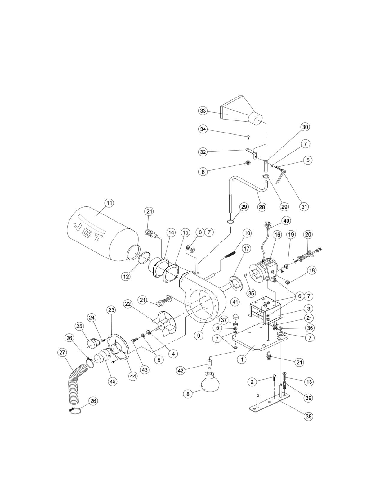
10.1.1 DC-500P Portable Dust Collector – Exploded View
12

10.1.2 DC-500P Portable Dust Collector – Parts List
Index No Part No Description Size Qty
1 ................ DC500P-001 ............. Base......................................................................... ...................................... 1
2 ................ DC500P-002 ............. Hex Cap Lag Screw ................................................. ST9.5x50 mm ............... 1
3 ................ DC500P-003 ............. Motor Base .............................................................. ...................................... 1
4 ................ DC500P-004 ............. Washer .................................................................... ...................................... 1
5 ................ TS-2361081 .............. Lock Washer ............................................................ 8mm .............................. 5
6 ................ TS-2311081 .............. Hex Nut .................................................................... M8 .. ............................. 15
7 ................ TS-1550061 .............. Flat Washer ............................................................. 8mm ............................ 11
8 ................ DC500P-008 ............. Caster ...................................................................... ...................................... 4
9 ................ DC500P-009 ............. Impeller Housing ...................................................... ...................................... 1
10 .............. DC500P-010 ............. Handle Grip.............................................................. ...................................... 1
11 .............. DC500P-011 ............. Collector Bag ........................................................... ...................................... 1
12 .............. DC500P-012 ............. Wire Clamp .............................................................. Ø5" ................................ 1
13 .............. DC500P-013 ............. Phillips Self-Tapping Screw ..................................... ST6.3x32 mm ............... 2
14 .............. DC500P-014 ............. Exhaust Flange ........................................................ ........... ........................... 1
15 .............. DC500P-015 ............. Gasket ..................................................................... ...................................... 1
16 .............. DC500P-016 ............. Motor Assembly ...................................................... 3/4HP 115V .................. 1
…………….DC500P-016WD ....... Wiring Diagram (not shown) .................................... ...................................... 1
.................. DC500P-016ML ........ Motor Label, DC500P (not shown) .......................... ...................................... 1
…………….DC500P-016MF ........ Motor Fan (not shown)............................................. ...................................... 1
…………….DC500P-016RC. ....... Running Capacitor (not shown) ............................... 40μF, 450V ................... 1
…………….DC500P-016JB ......... Junction Box (not shown) ........................................ ...................................... 1
…………….DC500P-016JBC ....... Junction Box Cover (not shown) .............................. ...................................... 1
17 .............. DC500P-017 ............. Motor Gasket ........................................................... ...................................... 1
18 .............. DC500P-018 ............. Switch with Key........................................................ ...................................... 1
19 .............. DC500P-019 ............. Strain Relief ............................................................. ....... ............................... 1
20 .............. DC500P-020 ............. Power Cord with Plug .............................................. 16AWGx3C, 7-1/2ft ....... 1
21 .............. TS-1490031 .............. Hex Head Bolt.......................................................... M8x20 ......................... 17
22 .............. DC500P-022 ............. Impeller .................................................................... ...................................... 1
23 .............. DC500P-023 ............. Cover Assembly....................................................... ...................................... 1
24 .............. DC500P-024 ............. Philips Pan Hd Self-Tapping Screw ......................... ST4.2x12.7 mm .......... 10
25 .............. DC500P-025 ............. Inlet Cap ................................................................. ...................................... 1
26 .............. DC500P-026 ............. Wire Clamp .............................................................. Ø4" ................................ 2
27 .............. DC500P-027 ............. Flexible Hose ........................................................... Ø4" x 10' ....................... 1
28 .............. DC500P-028 ............. Lower Support Tube ................................................ ...................................... 1
29 .............. DC500P-029 ............. Butterfly Clamp ........................................................ ...................................... 2
30 .............. DC500P-030 ............. Upper Support Tube ................................................ ...................................... 1
31 .............. DC500P-031 ............. Locking Handle ........................................................ ...................................... 1
32 .............. DC500P-032 ............. Funnel Support Bracket ........................................... ...................................... 1
33 .............. DC500P-033 ............. Dust Funnel ............................................................. ...................................... 1
34 .............. DC500P-034 ............. Carriage Bolt ............................................................ M8x20 ........................... 2
35 .............. DC500P-035 ............. Key Dbl Rd Hd ......................................................... C6x25mm ..................... 1
36 .............. TS-1541031 .............. Nylon Lock Hex Nut ................................................. M8 ................................. 2
37 .............. TS-2342101 .............. Nylon Lock Hex Nut ................................................. M10 ............................... 4
38 .............. DC500P-038 ............. Wall Mount Plate...................................................... ...................................... 1
39 .............. DC500P-039 ............. Screw Anchor .......................................................... ...................................... 2
40 .............. DC500P-040 .............
41 .............. TS-2331081 .............. Cap Nut .................................................................. M8 ................................. 4
42 .............. DC500P-042 ............. Sleeve ..................................................................... ...................................... 4
43 .............. TS-1490031 .............. Hex Cap Screw ........................................................ M 8x20 ........................... 1
44 .............. JWBS14SFX-179 ...... Philips Pan Head Self-Tapping Screw ..................... ST4.2x10 ...................... 3
45 .............. DC500P-045 ............. Inlet Adapter ............................................................ ...................................... 1
.................. LM000353 ................. ID Label, DC-500P (not shown) ............................... ...................................... 1
.................. LM000355 ................. Warning Label, DC-500P (not shown) ..................... ...................................... 1
.................. LM000356 ................. Rotation Label, DC-500P (not shown) ..................... ...................................... 1
.................. JET-92 ....................... JET Logo (not shown) ............................................. 92x38mm ...................... 1
Ground wire ........................................................... ...................................... 1
13

11.0 Electrical Connections for DC-500P
11.1 Electrical Connections for 3/4HP, 1PH, 115V only
11.2 Electrical Connections for 3/4HP, 1PH, 230V only
14

12.0 Warranty and service
JET warrants every product it sells against manufacturers’ defects. If one of our tools needs service or repair, please
contact Technical Service by calling 1-800-274-6846, 8AM to 5PM CST, Monday through Friday.
Warranty Period
The general warranty lasts for the time period specified in the literature included with your product or on the official
JET branded website.
• JET products carry a limited warranty which varies in duration based upon the product. (See chart below)
• Accessories carry a limited warranty of one year from the date of receipt.
• Consumable items are defined as expendable parts or accessories expected to become inoperable within a
reasonable amount of use and are covered by a 90 day limited warranty against manufacturer’s defects.
Who is Covered
This warranty covers only the initial purchaser of the product from the date of delivery.
What is Covered
This warranty covers any defects in workmanship or materials subject to the limitations stated below. This warranty
does not cover failures due directly or indirectly to misuse, abuse, negligence or accidents, normal wear-and-tear,
improper repair, alterations or lack of maintenance. JET woodworking machinery is designed to be used with Wood.
Use of these machines in the processing of metal, plastics, or other materials outside recommended guidelines may
void the warranty. The exceptions are acrylics and other natural items that are made specifically for wood turning.
Warranty Limitations
Woodworking products with a Five Year Warranty that are used for commercial or industrial purposes default to a
Two Year Warranty. Please contact Technical Service at 1-800-274-6846 for further clarification.
How to Get Technical Support
Please contact Technical Service by calling 1-800-274-6846. Please note that you will be asked to provide proof
of initial purchase when calling. If a product requires further inspection, the Technical Service representative will
explain and assist with any additional action needed. JET has Authorized Service Centers located throughout the
United States. For the name of an Authorized Service Center in your area call 1-800-274-6846 or use the Service
Center Locator on the JET website.
More Information
JET is constantly adding new products. For complete, up-to-date product information, check with your local distributor
or visit the JET website.
How State Law Applies
This warranty gives you specific legal rights, subject to applicable state law.
Limitations on This Warranty
JET LIMITS ALL IMPLIED WARRANTIES TO THE PERIOD OF THE LIMITED WARRANTY FOR EACH PRODUCT.
EXCEPT AS STATED HEREIN, ANY IMPLIED WARRANTIES OF MERCHANTABILITY AND FITNESS FOR A
PARTICULAR PURPOSE ARE EXCLUDED. SOME STATES DO NOT ALLOW LIMITATIONS ON HOW LONG AN
IMPLIED WARRANTY LASTS, SO THE ABOVE LIMITATION MAY NOT APPLY TO YOU.
JET SHALL IN NO EVENT BE LIABLE FOR DEATH, INJURIES TO PERSONS OR PROPERTY, OR FOR
INCIDENTAL, CONTINGENT, SPECIAL, OR CONSEQUENTIAL DAMAGES ARISING FROM THE USE OF OUR
PRODUCTS. SOME STATES DO NOT ALLOW THE EXCLUSION OR LIMITATION OF INCIDENTAL OR
CONSEQUENTIAL DAMAGES, SO THE ABOVE LIMITATION OR EXCLUSION MAY NOT APPLY TO YOU.
JET sells through distributors only. The specifications listed in JET printed materials and on official JET website are
given as general information and are not binding. JET reserves the right to effect at any time, without prior notice,
those alterations to parts, fittings, and accessory equipment which they may deem necessary for any reason
whatsoever. JET
Product Listing with Warranty Period
90 Days – Parts; Consumable items
1 Year – Motors; Machine Accessories
2 Year – Metalworking Machinery; Electric Hoists, Electric Hoist Accessories; Woodworking Machinery used
for industrial or commercial purposes
5 Year – Woodworking Machinery
Limited Lifetime – JET Parallel clamps; VOLT Series Electric Hoists; Manual Hoists; Manual Hoist
Accessories; Shop Tools; Warehouse & Dock products; Hand Tools; Air Tools
NOTE: JET is a division of JPW Industries, Inc. References in this document to JET also apply to JPW Industries,
Inc., or any of its successors in interest to the JET brand.
®
branded products are not sold in Canada by JPW Industries, Inc.
15

427 New Sanford Road
LaVergne, Tennessee 37086
Phone: 800-274-6848
www.jettools.com
16
 Loading...