

Page 1

Operati ng Instructions
16” x 40” CN C Lathe
Model CL-1640ZX
WALTER MEIER (Manuf acturing) Inc.
427 New Sanford Road
LaVergne, T N 37086 Part No. M- 320930
Ph.: 800-274-6848 Revision A 9/09
www.walt er meier.c om Copyright © 2009 Walt er Meier (M anufacturi ng),I nc.
Page 2
W arranty and Service
Walter Meier (Manufacturing) Inc., warrants every product it sells. If one of our tools needs service or repair, one of
our Authorized Service Centers located throughout the United States can give you quick service. In most cases, any
of these Walter Meier Authorized Service Centers can authorize warranty repair, assist you in obtaining parts, or
®
perform routine maintenance and major repair on your JET
your area call 1-800-274-6848.
MORE INFORMATION
Walter Meier is consistently adding new products to the line. For complete, up-to-date product information, check with
your local Walter Meier distributor, or visit jettools.com.
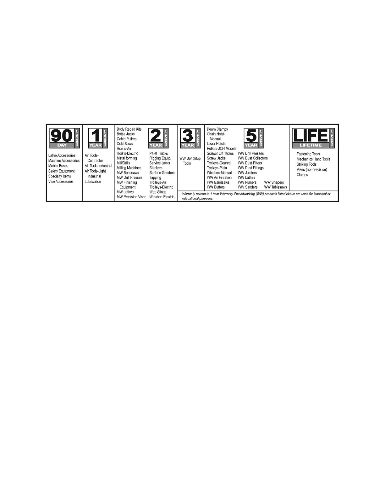
WARRANTY
JET products carry a limited warranty which varies in duratio n based upon the product (MW = Metalworking, WW =
Woodworking).
WHAT IS COVERED?
This warranty covers any defects in workmanship or materials subject to the e xceptions stated below. Cutting tools,
abrasives and other consumables are excluded from warranty coverage.
WHO IS COVERED?
This warranty covers only the initial purchaser of the product.
WHAT IS THE PERIOD OF COVERAGE?
The general JET warranty lasts for the time period specified in the product literature of each product.
WHAT IS NOT COVERED?
Five Year Warranties do not cover woodworking (WW) products used for commercial, industrial or educational
purposes. Woodworking products with Five Year Warranties that are used for commercial, industrial or education
purposes revert to a One Year Warranty. This warranty does not cover defects due directly or indirectly to misuse,
abuse, negligence or accidents, normal wear-and-tear, improper repair or alterations, or lack of maintenance.
HOW TO GET SERVICE
The product or part must be returned for examination, postage prepaid, to a location designated by us. For the name
of the location nearest you, please call 1-800-274-6848.
You must provide proof of initial purchase date and an explanation of the complaint must accompany the
merchandise. If our inspection discloses a defect, we will repair or replace the product, or refund the purchase price,
at our option. We will return the repaired product or replacement at our expense unless it is determined by us that
there is no defect, or that the defect resulted from causes not within the scope of our warranty in which case we will,
at your direction, dispose of or return the product. In the event you choose to have the product returned, you will be
responsible for the shipping and handling costs of the return.
HOW STATE LAW APPLIES
This warranty gives you specific legal rights; you may also have other rights which vary from state to state.
LIMITATIONS ON THIS WARRANTY
WALTER MEIER (MANUFACTURING) INC., LIMITS ALL IMPLIED WARRANTIES TO THE PERIOD OF THE
LIMITED WARRANTY FOR EACH PRODUCT. EXCEPT AS STATED HEREIN, ANY IMPLIED WARRANTIES OR
MERCHANTABILITY AND FITNESS ARE EXCLUDED. SOME ST ATES DO NOT ALLOW LIMITATIONS ON HOW
LONG THE IMPLIED WARRANTY LASTS, SO THE ABOVE LIMITATION MAY NOT APPLY TO YOU.
WALTER MEIER SHALL IN NO EVENT BE LIABLE FOR DEATH, INJURIES TO PERSONS OR PROPERTY, OR
FOR INCIDENTAL, CONTINGENT, SPECIAL, OR CONSEQUENTIAL DAMAGES ARISING FROM THE USE OF
OUR PRODUCTS. SOME STATES DO NOT ALLOW THE EXCLUSION OR LIMITATION OF INCIDENTAL OR
CONSEQUENTIAL DAMAGES, SO THE ABOVE LIMITATION OR EXCLUSION MAY NOT APPLY TO YOU.
Walter Meier sells through distributors only. The specifications in Walter Meier catalogs are given as general
information and are not binding. Members of Walter Meier reserve the right to effect at any time, without prior notice,
those alterations to parts, fittings, and accessory equipment which they may deem necessary for any reason
®
whatsoever. JET
branded products are not sold in Canada by Walter Meier.
tools. For the name of an Authorized Service Center in
2
Page 3

Table of Contents
Warranty and Service..........................................................................................................................2
Table of Contents ...............................................................................................................................3
Warn in g .............................................................................................................................................4
In trodu ction ........................................................................................................................................6
Description .........................................................................................................................................6
Spe cifi cation s .....................................................................................................................................7
Unpacking ..........................................................................................................................................8
Contents of the Shipping Container ..................................................................................................8
Uncrating and Set-Up..........................................................................................................................9
Chuck Preparation (Three Jaw) ........................................................................................................9
Electrical Connect io ns....................................................................................................................... 10
Coolant Preparation....................................................................................................................... 11
Oil Lubricator ................................................................................................................................ 11
General Description .......................................................................................................................... 11
Lathe Bed ..................................................................................................................................... 11
Headstock..................................................................................................................................... 11
Spin dle ......................................................................................................................................... 12
Ca rriage ....................................................................................................................................... 12
Cross Slide ................................................................................................................................... 12
Four Way Tool Post ....................................................................................................................... 12
Tai lsto ck ....................................................................................................................................... 12
Work Lamp ................................................................................................................................... 12
Coolant Nozzle.............................................................................................................................. 12
Adju s tmen ts ..................................................................................................................................... 13
Headstock Alignment ..................................................................................................................... 13
Tailstock Adjust ments .................................................................................................................... 13
Aligning Tailstock t o Headstock ...................................................................................................... 14
Gap Section .................................................................................................................................. 15
Belt Replacement and Adjustment .................................................................................................. 15
Pre-Operation Inspection................................................................................................................... 16
Mai ntenan ce .................................................................................................................................... 16
Operating Controls............................................................................................................................ 17
3
Page 4

Warning
1. Read and understand the entire instruction manual, programming manual, and CNC system
operation before attempting to use this machine.
2. Read and understand the warnings posted on t he mac hine and in this manual. Failure to c omply with
all of these warnings may cause serio us injury.
3. Replace the warning labels if they become obscured or removed.
4. This lathe is desig ned and intended for us e by properly tr ained and experienced perso nne l o nly. If
you are not fami liar w ith t he proper and safe oper at ion of a lathe, do not use until proper trai ning a nd
knowledge have bee n obtai ned.
5. Do not use this lathe for other than its intended use. If used for other purposes, Walter Meier
(Manufacturing) Inc., disclaims any real or implied w arranty and holds itself harmless f rom any injury
that may result from that use.
6. Always wear appr oved saf ety glasses/ face s hields w hile using t his lathe. E veryday eyeg lasses o nly
have impact resistant lenses; t hey are not safety glasses.
7. Before operating this lathe, remo ve tie, rings, wat ches and ot her jew elry, and r oll sleeves up past the
elbows. Remove all loos e clothing a nd confi ne lo ng hair . Non-slip foot wear or anti-skid floor st r ips ar e
recommended. Do not wear gloves.
8. Never place hands near or ar ound revolving tool or part.
9. Wear ear pr otect or s (plugs or muffs ) during exte nded periods of oper at ion.
10. Some dust created by power sanding, sawing, grinding, drilling and other construction activities
contain chemicals k nown to cause cancer, birt h defects or ot her reproductive harm. Some e xamples
of these chemicals are:
• Lead from lead based paint.
• Crystalline silica from bricks, cement and ot her masonry products.
• Arsenic and chromium fr om chemically treated lumber.
Your risk of exposure varies, depending on how often you do this type of work. To reduce yo ur
exposure to these chemicals, work in a well-ventilated area and work with approved safety
equipment, such as face or dust masks that are specifically designed to filter out microscopic
particles.
11. Do not operat e t his machine while tired or under the influence of drugs, alco hol or any medication.
12. M ake c er t ain the switch is in the OFF position before connecti ng the machine t o t he power s upply.
13. M ake c er t ain the machine is properly grounded.
14. M ake all machine adj ustments or mainte nance with the machine unplugged fr om the power source.
15. Remove adjusting keys and wrenches. Form a habit of checking to see that keys and adjusting
wrenches are removed from the mac hine before tur ning it on.
16. Keep safety guards in place at all times when the machine is in use. If removed for maintenance
purposes, use extreme cautio n and replace t he guards immed iately af t er maintenance is complet e.
17. Never use this machine with a cover ope n, removed or damaged. Replace, close or repair damaged
covers before f urther use of this machine.
18. Check damaged parts. Before further use of the machine, a guard or other part that is damaged
should be carefully checked to determine that it will operate properly and perform its intended
function. Check for alignme nt of moving part s, binding of moving part s, break age of part s, mounting
and any other condit ions t hat may affect its oper ation. A guard or other part that is damaged s hould
be properly repaired or r eplaced.
19. Pr ovide for adequate space surroundi ng work ar ea and non-glare, overhead lighti ng.
20. Keep t he floor around t he machi ne clean and free of scr ap material, oil and grease.
4
Page 5

21. Keep visitor s a s af e dist ance from the work ar ea. Keep children away.
22. M ake your wor kshop child proof with padlocks, master switches or by removing start er keys.
23. Give your work undivided att ention. Looking aro und, carrying on a conversat ion and “ horse-play” are
careless acts that can result in serious injury.
24. Maintain a b alanced st ance at al l times so that yo u do not fall or lea n against movi ng parts. Do not
overreach or use excessive force t o per form any machine operation. Never forc e t he cutting action.
25. Use t he r ig ht t ool at the correct speed and feed rate. Do not force a t ool or at t achme nt to do a jo b for
which it w a s not d e s igned. The right t o o l will do the job be tt er and sa fer .
26. Use r ecommended acces sor ies; improper acces sor ies may be hazardous.
27. Maintain tools with care. Keep cutting tools sharp and clean for the best and safest performance.
Follow instructions f or lubricating and c hangi ng accessories.
28. Do not use this machine in a da ngerous e nvironme nt, such as a w et or r ain-dr enched ar ea, or near
explosive gases. T he works ite should be well illuminated.
29. Do not att empt t o adjust or r emove tools during operatio n.
30. Tur n off the machine and disco nnect fr om pow er bef or e cleaning. Use a br ush to remo ve s havings or
debris — do not use your ha nds.
31. Do not stand on the machine. Serious injury could occur if the machine tips over.
32. Never leave the machine running unattended. Tur n the power of f and do not leave the machi ne until it
comes to a complete stop.
33. Remo ve loose items a nd unnecessary work pieces f r om the area befor e starting the machine.
34. The power supply f or t his machine must be three phase, using four wires , one of w hich is a grounding
wire. It must be positively gro unded to prevent electrical s hock a nd possible f atal injury. Check the
voltage – if there is a local voltage f luctuatio n, a stabilizer must be i nstalled.
Familiarize yours elf with the f ollow ing saf et y not ices used in t his manual:
This means that if precautions are not heeded, it may result i n minor injury and/or
possible machine damage.
This means that if precautions are not heeded, it may result i n serio us injury or possibly
even death.
- - SAVE THE SE INST RUCTI ONS - -
5
Page 6

Introduction
This manual is provided by Walter Meier (Manufacturing) Inc., covering the safe operation and
maintenance pr ocedures for a JET M odel CL-1640 ZX CNC Lat he. This ma nual co ntains instructio ns o n
installation, s afety precautions, g eneral operat ing procedures, descri ption of mec hanical elements, a nd
ma intenance instructi ons .
This mac hi ne has bee n desig ned and constructed t o provide years of trouble free operat ion if used in
accordance with instructions set forth in this manual. If there are any questions or comments, please
contact either your local supplier or Walter Meier. Walter Meier can also be reached at our web site:
www.wmhtoolgroup.com.
Description
This JET lathe adapts t he A nilam® 4200T CNC system to control the various cutting actions. The CNC
system is designed for ease of use and intuitive interaction, which means no prior programming
experience is needed. A Shape Editor allows drawing a part graphically and creating the tool path without
programmi ng. A Tool Page provides grap hical descriptio n of 99 tools, so t he operat or can specify t ool
radius, length and wear of fsets, etc.
The longitudi nal and cross feeds ar e dr iven by servo motors.
This lathe is espec ial ly suited f or mac hining step axles or sleeve w or kpieces. It can also mac hine t aper s,
do circular curves, and automatic t hreading. The tool post w ill ra ise, revolv e, p osit io n, clamp and c ha nge
too ls a uto mat ic a lly. The lathe will also a c c e pt an elec tr ic o r hyd r aul ic c h uc k .
The lathe has a Teach-In mode, in which a par t may be manufactured manual ly while the 4200T r ecor ds
the correspondi ng program for lat er r eplication.
6
Page 7

Specifications
Model Number .................................................................................................................... CL-1640ZX
Stock Number .......................................................................................................................... 320930
Computer Cont rols:
Anilam 4200T wit h 12.1” TFT Color Flat Scr een
8.0 GB Hard Drive with Flash Memory, 266M Hz Dual Processor
floppy disk drive; flas h card reader
Spin dle Motor ............................................................................................ 10HP , 3Ph, 220V only, 60 Hz
Servo Motors ........................................................................................................................ 1 .0/1.5K W
Capacities:
Swing over Bed (in.).......................................................................................................................... 16
Swing over Cross Slide (in.) .............................................................................................................. 10
Maxi mum Swing Through Gap (in.) .............................................................................................. 25-7/8
Length of Gap (in.) ...................................................................................................................... 12-1/4
Distance between Centers (in.) .......................................................................................................... 40
Spindle Bore (in.) .......................................................................................................................... 3-1/8
Spindle Mount .............................................................................................................................. D1-8
Spindle Taper ............................................................................................................................... MT-7
Range of Spindle Speeds (RPM) ........................................................ infinitely variable within 80 to 2000
Rapid Feed, X-axis (in./ min.) ........................................................................................................... 315
Rapid Feed, Z-a xis (in./ min.)............................................................................................................ 394
Minimum Input (X/Z)(in.)............................................................................................................0.00004
Tool Post..................................................................................................................4 station auto matic
Maxi mum Tool Size (in.)................................................................................................................ 1 x 1
Maxi mum Cross Slide Travel (X) (in.) ................................................................................................... 9
Maximum Carriage Travel ( Z) ( in.) ..................................................................................................... 35
Tailstock Spindle Travel (in.)................................................................................................................ 5
Tailstock Taper ............................................................................................................................. MT-5
Width of Bed (in.) ........................................................................................................................ 1 3-1/4
Overall Dimensions (in.)(LxWxH) ........................................................................................ 50 x 92 x 64
Approximate Net Weig ht (lbs.) ....................................................................................................... 5566
The above specificati ons were current at t he time this ma nual w as publis hed, but because of our policy of
continuo us impro vement, Walt er M eier ( M anufacturi ng) Inc., res er ves the right to change spec ificat io ns at
any time and without prior notice, w ithout i ncurri ng obligations.
7
Page 8
Unpacking
Open shipping co ntainer a nd check for s hipping
damage. Report any damage immediately to
your distributor and shipping agent. Do not
discard any shipping material until the Lathe is
assembled a nd running properly.
Compare the conte nts of y our container with t he
following parts list to make sure all parts are
intact. Missing par ts, if any, should be reported
to your dist ributor. Read the instr uction manual
thoroughly for assembly, maintenance and
safety instructions.
Contents of the Shipping Container
1 Lathe
1 10” Three-Jaw Chuck (mounted on Lathe)
1 12” Face Plate
1 Laptop Computer Tray
1 Air Hose with Blower Gun
1 Anilam® Cont rols man ua l
1 Operat ing Instructions Manual
1 Parts List & Electr ical Diagram Ma nual
1 Warranty Card
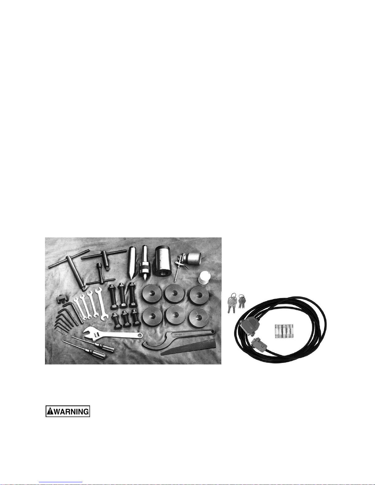
1 Tool Box containing (see Figure1) :
1 Open End Wrench Set
1 Hex (Allen) Wrench Set
1 Spindle Sleeve
1 Live Center, M T- 4
1 Dead Center, M T-5
6 Leveling Bolts
6 Leveling Pads
1 Flat Blade Screwdr iver
1 Cross Po int Scr ewdr iver
1 Chuck Key
1 Tool Post Wrench
1 Cam Wrench
1 Adjustable Wrench
1 Oil Gun
1 To uch-up Pa int Can
1 Gap Bridge Pin Driver
1 Wedge
1 Serial Cable
5 Extra Fuses
2 Sets of keys (electrical box/main switch)
Read and underst and the entire contents of this manual before att empt ing set-
up or operation! Failure to comp ly may cause ser iou s injur y.
Figure 1
contents of Tool Box
8
Page 9
Uncrating and S et-Up
1. Finish removing the wooden crate and
packing materials f r om around the lathe.
2. Unbolt lathe from the shipping crat e pallet.
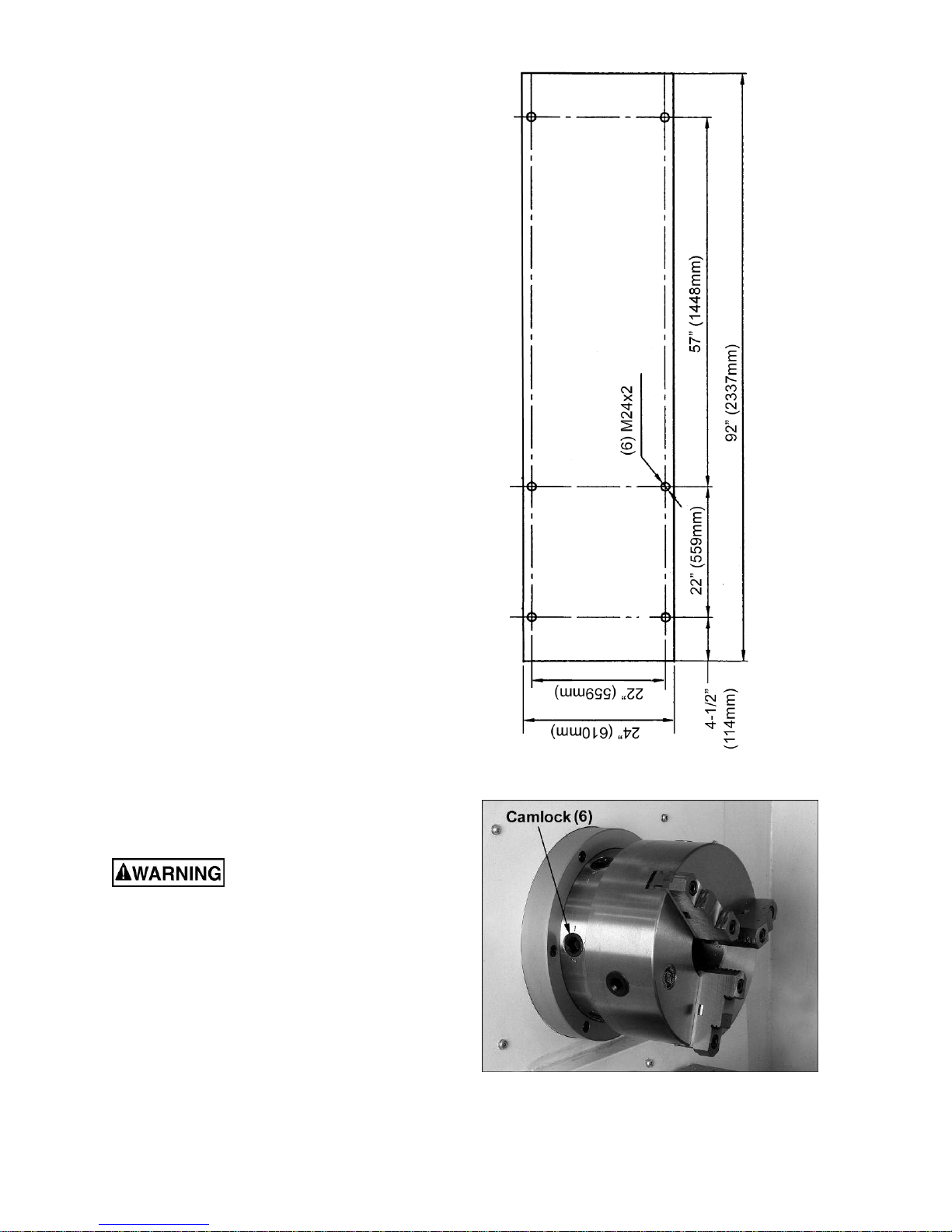
3. Choose a location for the lathe that is dry,
well illuminated, and has enough room to
allow servicing the lathe on all four sides.
Make sure the floor is able to support the
weight of the mac hine. Fig ure 2 shows hole
centerlines for securing the machine dir ect ly
to a concrete floor. NOTE: Confirm these
dimensions by measuring on your machine,
bef o r e d rilli ng holes .
4. Sling or fork the lat he. Do not lift lathe by
the spindle. Mo ve the tailstock to the right
side of the bed t o bal ance t he mac hine; lock
the tailstock tightly to the bed. With
adequate lifti ng equip ment, slowly raise the
lathe off the shipping crate bottom. Make
sure lathe is balanced befor e moving.
5. To avoid twisting the bed, the lathe’s
location must be flat and level. When the
lathe is posit ione d, check f or le vel by usi ng
a machinist’s precisio n le vel on t he bedways
both front to back and side to side. Leveling
pads and screws included i n the tool box will
help you reac h a le vel condit ion. The lathe
must be level to be accurate.
6. Clean all rust protected surfaces using a
mild commercia l solvent, kerosene or diesel
fuel. Do not use paint thinner, gasoline, or
lacquer thinner, as these may damage
painted s urfaces. Cover all clea ned surfac es
with a light film of 20W machine oil.
7. Remove the four shipping brackets that
secure the slidi ng door fr om the inside (2 at
top, 2 at bottom).
Chu ck P reparati on ( Three Jaw)
Read and understand all
directions for chuck preparation. Failure to
comply may cause serious injury and/or
damage to the lathe.
NOTE: Before removing chuck from the spind le,
place a f lat piec e of wood acros s the bedway s
under the chuck to prevent damage to the
bedways should the chuck fall fr om your hands.
1. Support the chuck while turning the six
camlocks 1/4 turn counterclockwise, using
the chuck wrench from the tool box. See
Figure 3.
Figure 2
Figure 3
9
Page 10
2. Carefully re mo ve t he c huck f r om the spi ndle
and place on an adequate wor k surfac e.
3. Inspect the ca mlock studs. Make sure they
have not become cracked or broken during
transit. Clean all parts thoroughly with
solvent. Also clean the spindle and
camlocks.
4. Cover all chuck jaws and scroll inside the
chuck with #2 lithium tube greas e. Cover the
spindle, camlocks, and chuck body with a
lig ht film of 2 0 W machi ne oil.
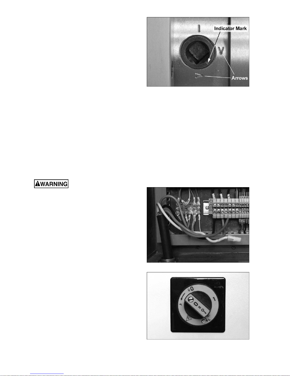
5. Lift the chuck up to the spindle nose and
press o nto the s pindle. Tig ht en in place by
turning the camlocks 1/4 tur n clockwise. The
index mark on the camlock should be
between the two indicator arrows when
tight, as shown in F igure 4.
6. If the index mark is not between the two
arrows, remove the chuck and adjust the
camlock studs by eit her tur ning o ut one f ul l
turn (if cams will not engage) or t urning in
one full turn (if cams turn beyond indicator
marks.)
7. Install chuck and tighte n in place.
Figure 4
Electrical Connections
Electrical connections must
be made by a qualified electrician in
compliance with all relevant codes. This
machine m ust be proper ly gr ounded while i n
use to help protect the operator from
electrical shock and poss ib le f at al injury.
The main motor is rated at 10 HP, 3 Phase,
220V only. Confirm that power available at the
lathe’s location is the same rating as the lathe.
When opening t he door of t he electrical bo x, firs t
remove the screws. Then push the button, pull
out on the handle and rotat e it counterclockw ise
to release t he door catch.
Bring t he power cable up thro ugh the bott om of
the electrical box (Figure 5), and connect the
lead wires to t he post and the gro unding wire t o
the plate on the left. (Consult the diagrams in
the M-320930-1 Parts Lists and Electrical
Diagrams manual.) Close the door of the
electrical box, and t urn on the power by rotat ing
the Master Sw it ch (Figure 6) clockwise.
Figure 5
NOTE: A safety device is installed which
prevents the electrical box door from being
opened at the same ti me as the Master Sw itch
is ON. You must close the electrica l box door in
order t o power on the lathe, or turn off t he lathe
in order to acc ess the electrical box.
Figure 6
10
Page 11
Power is co nnected pr operly when p us hing the
forward button o n t he c ont r ol p a nel ca use s th e
spindle to rotate counterclockwise as viewed
from the tailstock. If the chuck rotates in the
clockwise direction, disconnect the lathe from
the power source, switch any two of the three
power leads ( not the gree n ground wire) , and reconnect the lathe to the power source.
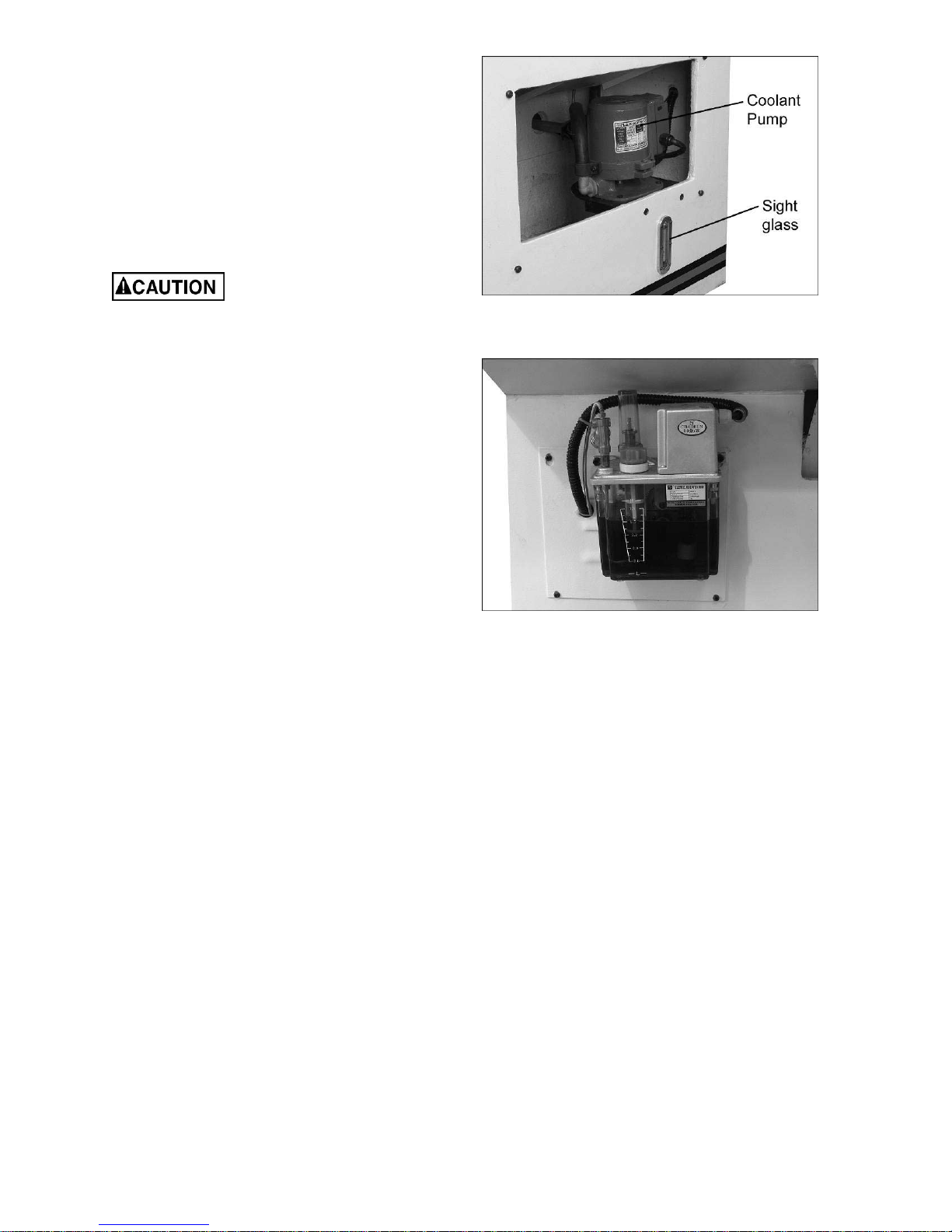
Coo lant P reparati on
Follow coolant manu-
facturer’s recommendations for use, care
and disposal.
1. Remo ve l ower access co ver o n the tailstock
end of the lat he. Make sure coolant pump
(Figure 7) has not shifted during tra nsport .
2. Pour approximately four gallons of coolant
mix into the drip pan.
3. After machine has been connected to
power, turn on coolant pump and ver ify that
coolant is cycling properly.
4. Replace lower ac cess c over.
5. Periodically chec k coolant level i n t he sig ht
glass (Figure 7) and top off as needed.
Oil Lubricator
The oil p ump at t he rear of the machine (F igure
8) provides an a utomat ic and co nstant supply of
lubricant to t he cross sl ide and bed ways area,
via the oil distribution tubes (shown in Figure
10). The reservoir should be checked frequent ly
and re-filled as needed. Use Mobil® DTE L ight
ISO32.
Ge neral Description
Lathe Bed
The lathe bed is made of high gr ade cast iron.
By combining high cheeks with strong cross
ribs, a bed w ith low vibrat ion and high ri gidity is
realized. Two precision ground v-slideways,
reinforced by ind ucti on hardening and gr inding,
accurately guide the c arriage and headstock. A
sliding safet y door wit h plexiglass is mo unted in
front of the bed. The main drive motor and
braking device ar e mo unted in the sta nd b elow
the headstock.
Headstock
The headstock is cast from high grade, low
vibratio n cast iro n, a nd bolt ed t o the bed by f our
socket head cap bolts.
Figure 7
Figure 8
11
Page 12
Spindle
The spindle is mounted in the headstock on
precision taper r oller bearings, a nd is ho llow t o
accept long stock, reducing preparation time
and waste of mater ial. It has a standard D-type
cam lock, and will accept manual or hydraulic
chucks.
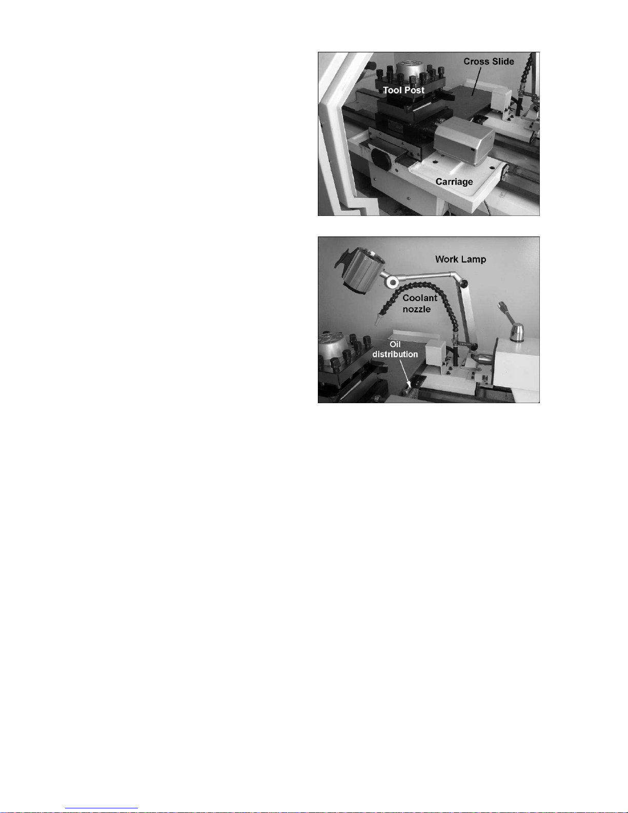
Carriage
The carriage (Figure 9) is made from high
quality cast iron. Longitudinal feed of the
carriage is effected by a ball screw which is
driven by the servo motor through an elastic
coupling.
Cross Slide
The cross slide (Figure 9) is mounted on the
carriage and moves along a dovetailed slide.
Cross feed is eff ected by a ball screw which is
driven by a servo motor through a synchrogeared belt in the pulley box.
Four Way Tool Post
The four way tool post (Figure 9) is mounted o n
the cross slide and allows a maximum of four
tools (not provided) to be mounted
simultaneously. Use a minimum of two
clamping screws when installing a tool.
Tailstock
The tailstock has a heavy duty quill wit h a No. 5
Morse Taper. It slides on a v-way and can be
locked at any location by a clamping lever.
When the load for the tailstock is especially
heavy, an eccentric shaft at the rear of the
tailstock can be tightened for auxiliary locki ng.
Figure 9
Figure 10
Wo rk Lamp
The adjustable work lamp (Figure 10) uses a
50W 24V bulb, and has an independent on/off
switch.
Coolant Nozzle
The nozzle (Figure 1 0) is f ully ad j ustable w ith an
independent on/off lever, and is fed from the
coolant pump.
12
Page 13
Adjustments
Headstock Ali gnm ent
Refer to Figur es 11 and 12.
The headstock has bee n alig ned at t he factor y
and should not require adjustment. However, if
correction is deemed necessary in the future,
the procedure is described below. It is
recommended that only qualified service
personne l perf or m this adjustment.
1. Using a machinist’s precision level on the
bedways, make s ure the lathe is level side
to side and fr ont to back. If the lathe is not
level, correct to a level condition before
proceeding.
2. Re-test alignment if any leveling
adjustments wer e made.
3. From steel bar stock of approximately two
inches in diameter, cut a piece
approximately eig ht i nches long.
4. Place two inches of bar stock in chuc k and
tighten chuck. Do not use the tailstock or
center to support t he other end.
Figure 11
5. Set up and cut alo ng fi ve inches of the bar
stock ( see Figure 11).
6. Using a micrometer, meas ure t he bar stock
next to the chuck and at the end. The
measureme nt should be the same.
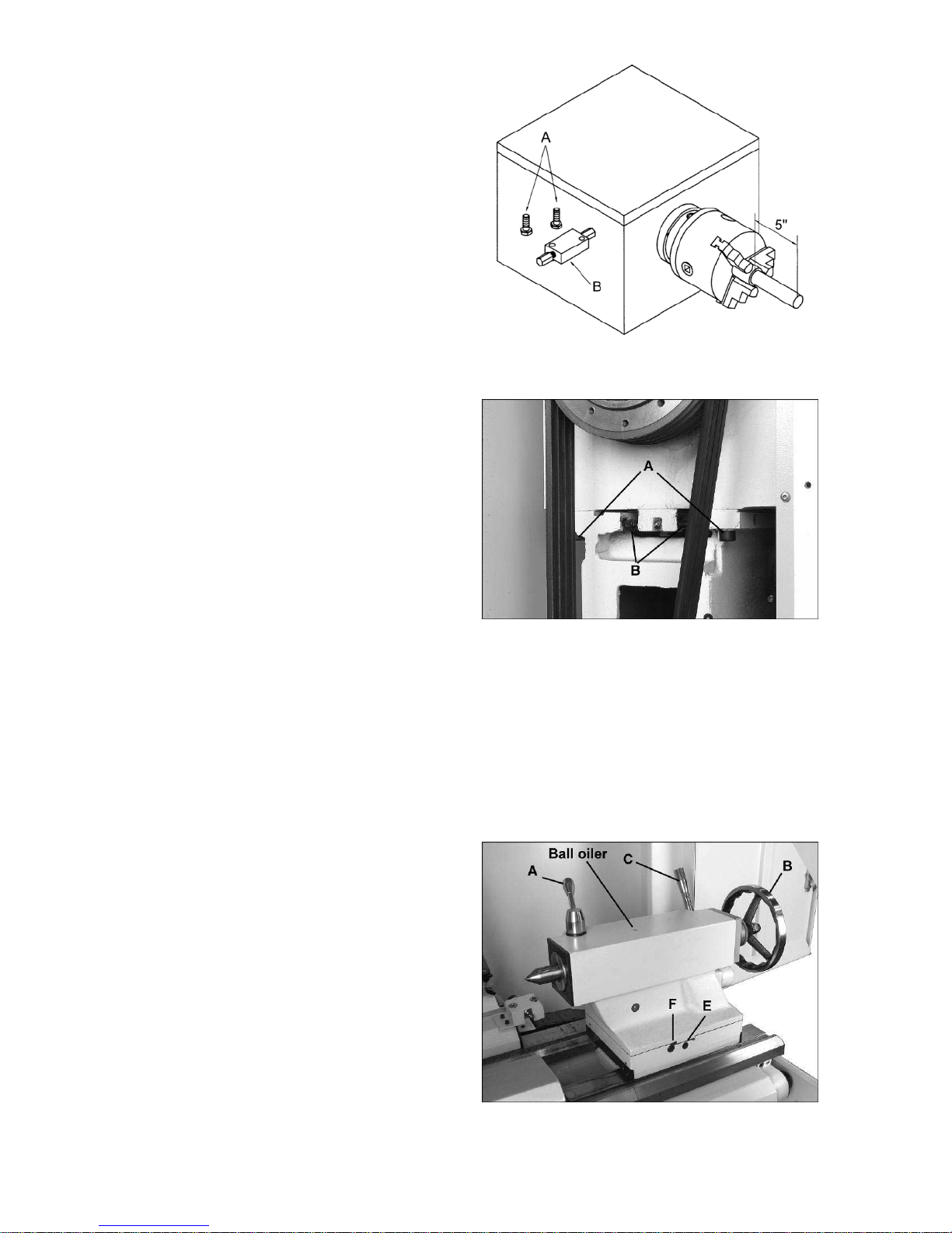
7. If t he measureme nts are not the same and
adjustment is required, loosen hex socket
cap screws (A, Figure 12) which hold the
headstock to the bed. DO NOT loosen
completely; some drag should remain.
8. Adjust tw o scr ew nuts (B) located at the end
of the headstock. Loosen one and tighten
the other. Make another cut. Keep adj usting
the screw nuts after each cut until the bar
stock measureme nts are t he same.
9. Securely tig hten headstock screw s ( A).
Tai l st ock Adjust ments
Refer to Figur es 13 and 14.
Quill Clamping Lever (A): Rotate clockwise to
lock the quill. Rotate counterclockwise to unlock.
The quill slee ve has a millimeter a nd inc h scale
(1/8” graduations).
Quill Traverse Handwheel (B): Rotate
clock wis e to a dva nce the qu ill, cou nte r c loc k wis e
to retract it. The handwheel has a revolution
scale in 0.002” increments.
Figure 12
Figure 13
13
Page 14
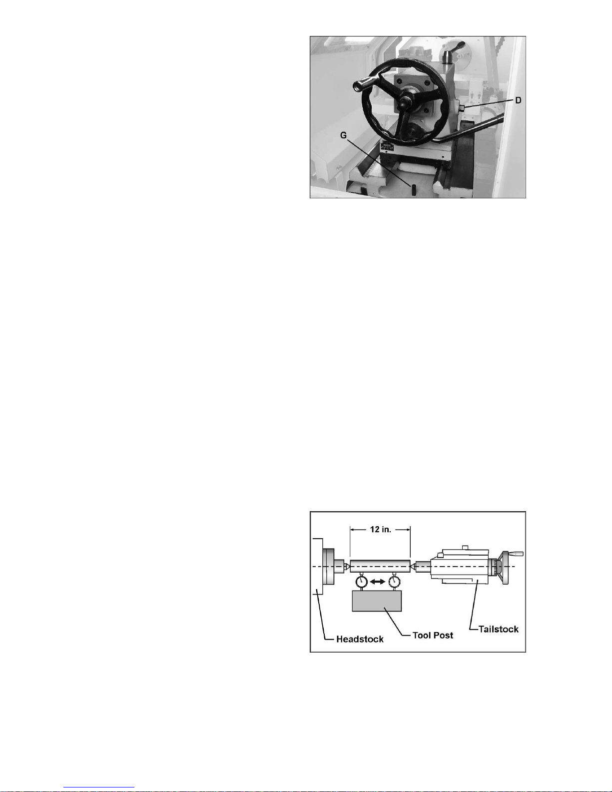
Clamping Lever (C): Lift up to lock. Push down
to unlock. If the tailstock is under heavy load,
tighten the ecce ntric shaft (D) at the back of the
tails toc k for a uxiliary lo c king.
NOTE: If the tailstock refuses to lock, do the
following:
1. Move handle to unlocked positio n.
2. Slide the tailstock to an area that allows
access to t he undersi de of t he tai lstoc k. You
may need to remove the stop pin (G) to do
this.
3. Tighten tai lst ock cla mping bolt (underside of
tailstock) 1/4 turn. Test for proper locking.
Repeat as necessary.
4. Re-install stop pin.
Off-Set Adjustment:
Refer to Figur es 13 and 14.
Follow this procedure to off-set the tailstock to
cut shallow tapers:
1. Lock t ailstock in positio n with t he clamping
lever (C).
2. Loosen eccentric shaft (D) at back of
tailstock.
3. Two hex socket cap screws are located at
the base on either side of the tailstock (E,
Figure 12 shows the one in front). Loosen
one of these while tightening the other.
Gibs: To take up any play in the tailstock,
tighten t he t wo gib screws ( F) on eit her side of
the tailstock base. CAUTION: Do not overtighten, as excessive tightening will lead to
premature wear of the gibs and mating parts.
Alignin g Tail st ock to Headsto ck
Before proc eeding, headstock alig nment s ho ul d
be verified. See “Headstock Alignment”.
Figure 14
1. Fit a 12” gro und steel bar betw een centers
of the headstock and tailstock (Figure 15).
2. Fit a dial indicator to the tool post and
traverse the center line of the bar.
3. I f tailstoc k adjustment is needed, alter nately
loosen and tighten front and rear hex socket
cap screw s (E, Figure 13).
Figure 15
14
Page 15
Gap Section
The gap section is sometimes removed on
lathes to allow room for working with a face
plate.
Refer to Figur e 16.
1. Use the provided gap bridge pin driver to
loosen and remove the two taper pins (A,
Figure 16). Place t he hex cap screw through
the driver a nd position o ver t he taper hole.
Tighten the screw into the taper hole and
continue tightening until the pin comes
loose. Remove pin.
2. Remove four hex socket cap screws (B),
and two hex cap bolts (C).
3. Gap sect ion can now be removed.
To re-install the gap section:
4. Clean the bottom and the ends of the gap
section thoroughly.
5. Set gap sectio n i n p lace and loosely instal l
the two hex cap bo lts (C) a nd the fo ur hex
socket cap screws (B).
6. Carefully alig n the gap with the bedways.
7. Push the taper pins (A) down through the
gap and into t he lat he bed.
8. Tighte n all screws.
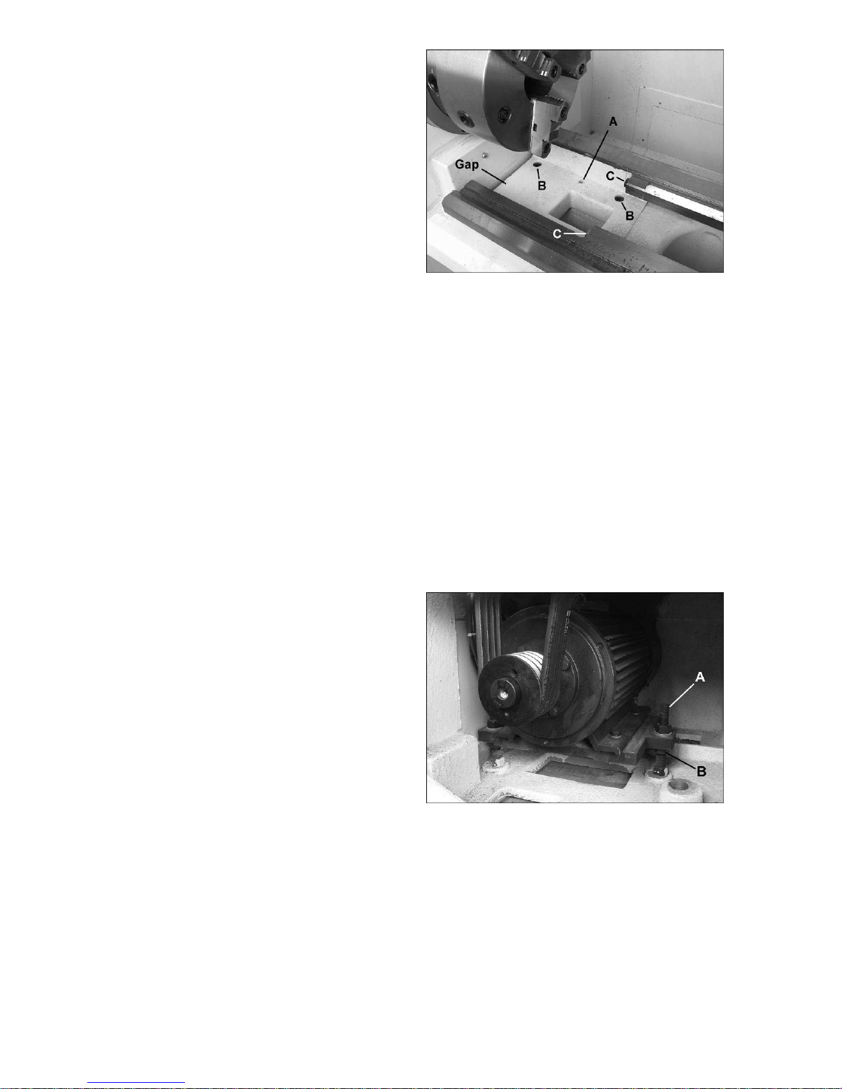
Belt Replacement and Adjustmen t
1. Disconnect machi ne from power s ource.
Figure 16
2. Open upper and lower side covers to
expose the motor and v-belts.
3. Loose n upper he x nut (A, Fi g ure 17). Place
scrap piece of wood under motor to act as
lever. Lift motor up and block temporarily.
4. Remove belts. I nstall new belts onto pulleys.
5. Lift up on motor and remove temporary
blocking.
6. Tension belts by loosening lower nut (B,
Figure 17) and tighte ning upper nut (A) until
light finger pressure causes approximately
3/4” def lect ion on each belt.
7. Install covers a nd connect lathe to power .
Figure 17
15
Page 16

Pre-Operation Inspection
Maintenance
Before at tempting to operate this lathe, t he user
should become t horo ug hly fami liar wit h both its
mechanical functions and CNC programming
functions. Read all provided manuals and
documentatio n that accompa nied t his mac hine.
1. Before operating this lathe, make sure all
necessary parts have proper l ubrication.
2. Manually check the working condition of
each part that will be involved in the
operations. Inspect the chuck by tightening
and lo osening it.
3. Tur n on the power – the power indicator will
light. Run the spindle from low speed up to
high wit hout load. Wat ch for proper s pindle
rotation direction. Lubrication should be
working properly. T ur n off the machi ne a nd
confirm that braki ng function is operable.
4. Listen for any strange sounds or vibratio ns;
if these should occur stop t he machine and
resolve the issue.
5. Before proc eedi ng with sta ndard operat io ns,
perform a test run to make sure the program
is correct.
Lathe must be ser viced at al l
lubrication points and al l reservoirs fi lled t o
operating level before the lathe is put into
service. Failure t o comply may cause serious
damage to the lathe.
1. After each shift, clean away chips, wipe
exposed parts of t he mac hine, and coat wit h
oil.
2. Regularly check the tightness of the drive
belts.
3. Reg ularly inspect the el ectrical bo x; remo ve
any dust.
4. Regularly clean dirt and chips from the
coolant tank. Check coolant level and
change the coolant periodical ly.
5. C hec k oil pu mp level and r e-f ill a s needed.
6. Periodically gr ease the track upon w hich the
sliding doors ride.
7. Daily lubricat e the tailstock t hroug h t he ba ll
oiler (see Figure 13) using Mobil® DTE Light
ISO32.
16
Page 17

Operating Controls
Below are explained the basic co ntrols f or manual operation of the lathe.
(For CNC pr ogr ammi ng, a nd f or e xplanat io n of the ma nual mode scr een display, co nsult the instr uctions
for the Anilam® 4200T CNC System, w hich accompanied yo ur machine.)
Figure 18
17
Page 18

NOTES
18
Page 19

19
Page 20

WALTER MEIER (Manuf acturing) In c.
427 New Sanford Road
LaVergne, TN 37086
Phone: 800-274-6848
www.waltermeier.com
20
Page 21

Parts Lists and Electrical Diagrams
for the CL-1640ZX Lathe
WALTER MEIER (Manuf acturing) In c.
427 New Sanford Road
LaVergne, Tennessee 37086 Part No. M- 320930- 1
Ph.: 800-274-6848 Revision B 04/2012
www.waltermeier.com Copyright © 2012 Walter Meier (Manufacturing) Inc.
Page 22

W arranty and S ervice
Walter Meier (Manufacturing) Inc., warrants every product it sells. If one of our tools needs service or repair, one of
our Authorized Service Centers located throughout the United States can give you quick service. In most cases, any
of these Walter Meier Authorized Service Centers can authori ze warranty repair, assist you in obtaining parts, or
®
perform routine maintenance and major repair on your JET
your area call 1-800-274-6848.
MORE INFORMATION
Walter Meier is consistently adding new products to the line. For complete, up-to-date product information, check with
your local Walter Meier distributor, or visit jettools.com.
WARRANTY
JET products carry a limited warranty which varies in duration based upon the product (MW = Metalworking, WW =
Woodworking).
WHAT IS COVERED?
This warranty covers any defects in workmanship or materials subject to the exceptions stated below. Cutting tools,
abrasives and other consumables are excluded from warranty coverage.
WHO IS COVERED?
This warranty covers only the initial purchaser of the product.
WHAT IS THE PERIOD OF COVERAGE?
The general JET warranty lasts for the time period specified in the product literature of each product.
WHAT IS NOT COVERED?
Five Year Warranties do not cover woodworking (WW) products used for commercial, industrial or educational
purposes. Woodworking products with Five Year Warranties that are used for commercial, industrial or education
purposes revert to a One Year Warranty. T his warranty does not cover defects due directly or indirectly to misuse,
abuse, negligence or accidents, normal wear-and-tear, improper repair or alterations, or lack of maintenance.
HOW TO GET SERVICE
The product or part must be returned for examination, postage prepaid, to a location designated by us. For the name
of the location nearest you, please call 1-800-274-6848.
You must provide proof of initial purchase date and an explanation of the complaint must accompany the
merchandise. If our inspection discloses a defect, we will repair or replace the product, or refund the purchase price,
at our option. We will return the repaired product or replacement at our expense unless it is determined by us that
there is no defect, or that the defect resulted from causes not within the scope of our warranty in which case we will,
at your direction, dispose of or return the product. In the event you choose to have the product returned, you will be
responsible for the shipping and handling costs of the return.
HOW STATE LAW APPLIES
This warranty gives you specific legal rights; you may also have other rights which vary from state to state.
LIMITATIONS ON THIS WARRANTY
WALTER MEIER (MANUFACTURING) INC., LIMITS ALL IMPLIED WARRANTIES TO THE PERIOD OF THE
LIMITED WARRANTY FOR EACH PRODUCT. EXCEPT AS STATED HEREIN, ANY IMPLIED WARRANTIES OR
MERCHANTABILITY AND FITNESS ARE EXCLUDED. SOME STATES DO NOT ALLOW LIMITATIONS ON HOW
LONG THE IMPLIED WARRANTY LASTS, SO THE ABOVE LIMITATION MAY NOT APPLY TO YOU.
WALTER MEIER SHALL IN NO EVENT BE LIABLE FOR DEAT H, INJURIES TO PERSONS OR PROPERTY, OR
FOR INCIDENTAL, CONTINGENT, SPECIAL, OR CONSEQUENT IAL DAMAGES ARISING FROM THE USE OF
OUR PRODUCTS. SOME STATES DO NOT ALLOW THE EXCLUSION OR LIMITATION OF INCIDENTAL OR
CONSEQUENTIAL DAMAGES, SO THE ABOVE LIMITATION OR EXCLUSION MAY NOT APPLY TO YOU.
Walter Meier sells through distributors only. The specifications in Walter Meier catalogs are given as general
information and are not binding. Members of Walter Meier reserve the right to effect at any time, without prior notice,
those alterations to parts, fittings, and accessory equipment which they may deem necessary for any reason
®
whatsoever. JET
branded products are not sold in Canada by Walter Meier.
tools. For the name of an Authorized Service Center in
2
Page 23

Table of Contents
Warranty and Service..........................................................................................................................2
Table of Contents ...............................................................................................................................3
Replacement Parts .............................................................................................................................3
Bed Assembly .................................................................................................................................4
Headstock Assembly I .....................................................................................................................6
Headstock Assembly II ....................................................................................................................8
Stand Assembly ............................................................................................................................ 10
Tailstock Assembly I ...................................................................................................................... 12
Tailstock Assembly II ..................................................................................................................... 14
Carriage Assembly ........................................................................................................................ 16
Protective Housing ........................................................................................................................ 18
Electrical Assembly ....................................................................................................................... 21
Miscellaneous Parts ...................................................................................................................... 23
Electrical Cabinet .......................................................................................................................... 24
Electrical Diagrams........................................................................................................................ 26
Replacement Parts
To order parts or reach our service department, call 1-800-274-6848, Monday through Friday (see our
website for business hours, www.waltermeier.com). Having the Model Number and Serial Number of your
machine available when you call will allow us to serve you quickly a nd accurately.
3
Page 24

Bed Asse mbly
4
Page 25

Bed Asse mbly
Index No. Part No. Description Size Qty
1 .............. ZX-01104 ................Bed.................................................................................................... 1
2 .............. CL1640ZX-0102 ......Hex Nut............................................................M12 ........................... 2
3 .............. ZX-05741 ................Threaded Tube ................................................................................... 2
4 .............. GB5782-M16x50......Hex Cap Bolt ....................................................M16x50 ...................... 8
5 .............. TS-155010 ..............Washer ............................................................16mm ........................ 8
6 .............. CL1640ZX-0106 ......Servo Motor .....................................................2HP, 98V ................... 1
7 .............. TS-1504061 ............Socket Head Cap Screw ...................................M8x30........................ 4
8 .............. TS-2361081 ............Helical Spring Lock Washer...............................8mm .......................... 4
9 .............. TS-1550061 ............Washer ............................................................8mm .......................... 4
10 ............ CL1640ZX-0110 ......Elastic Coupling ................................................DML02Y22Z/Y22Z ...... 1
11 ............ CL1640ZX-0111 ......Pin ...................................................................8x35mm ..................... 2
12 ............ TS-1505061 ............Socket Head Cap Screw ...................................M10x40 ...................... 4
13 ............ CL1640ZX-0113 ......Bracket .............................................................................................. 1
14 ............ TS-1550071 ............Washer ............................................................10mm ........................ 4
15 ............ TS-1501041 ............Socket Head Cap Screw ...................................M4x12........................ 4
16 ............ CL1640ZX-0116 ......Lock Nut ..........................................................M24x1.5 ..................... 1
17 ............ CL1640ZX-0117 ......Spacer ............................................................................................... 2
18 ............ CL1640ZX-0118 ......Oil Seal ............................................................35x51x8mm ............... 2
19 ............ CL1640ZX-0119 ......Bearing Housing ................................................................................. 1
20 ............ TS-1504041 ............Socket Head Cap Screw ...................................M8x20........................ 4
21 ............ CL1640ZX-0121 ......Bearing ............................................................25x62x34mm.............. 2
22 ............ CL1640ZX-0122 ......Flange ............................................................................................... 4
23 ............ TS-1503041 ............Socket Head Cap Screw ...................................M6x16........................ 6
29 ............ GB818-M5x10 .........Cross Recessed Pan Head Screw .....................M5x10...................... 16
30 ............ CL1640ZX-0130 ......Side Cover ......................................................................................... 2
31 ............ CL1640ZX-0131 ......Middle Bracket.................................................................................... 1
33 ............ CL1640ZX-0133 ......Ball Screw ........................................................1188x1710(1000) ....... 1
34 ............ TS-1504041 ............Hex Socket Cap Screw .....................................M8x20........................ 6
39 ............ CL1640ZX-0139 ......O-Ring .............................................................28x47x7 ..................... 1
40 ............ GB893.1-47 .............Retaining Ring ..................................................47mm ........................ 1
41 ............ CL1640ZX-0141 ......Bearing ............................................................20x47x14 ................... 1
42 ............ GB894.1-20 .............Retaining Ring ..................................................20mm ........................ 1
43 ............ CL1640ZX-0143 ......Back Bracket ...................................................................................... 1
44 ............ CL1640ZX-0144 ......Pin ...................................................................8x35mm ..................... 2
45 ............ TS-1504051 ............Hex Socket Cap Screw .....................................M8x25........................ 2
46 ............ CL1640ZX-0146 ......Back Cover ........................................................................................ 1
47 ............ CL1640ZX-0147 ......Ball Screw Housing Plate (1000).......................................................... 1
48 ............ CL1640ZX-0148 ......Hex Socket Cap Screw .....................................M12x55 ...................... 4
50 ............ CL1640ZX-0150 ......Pin ...................................................................12x70......................... 2
51 ............ TS-1550071 ............Washer ............................................................10mm ........................ 2
52 ............ ZX-01112 ................Saddle ............................................................................................... 1
53 ............ CL1640ZX-0153 ......Hex Cap Screw ................................................M10x55 ...................... 2
54 ............ CL1640ZX-0154 ......Washer ............................................................12mm ........................ 4
5
Page 26

Headstock A ssembly I
6
Page 27

Headstock A ssembly I
Index No. Part No. Description Size Qty
1 .............. TS-1504041 ............Headstock Casting.............................................................................. 1
2 .............. CL1640ZX-0202 ......Headstock Cover ................................................................................ 1
3 .............. TS-1503021 ............Hex Socket Cap Screw .....................................M6x10........................ 4
4 .............. CL1640ZX-0204 ......Hex Cap Bolt ....................................................M16x55 ...................... 2
5 .............. ZX-02736C ..............Positioning Pin.................................................................................... 1
6 .............. CL1640ZX-0206 ......Pin ...................................................................8x40 .......................... 2
7 .............. ZX-02744 ................Adjusting Screw .................................................................................. 2
8 .............. ZX-02124 ................Adjusting Block ................................................................................... 1
9 .............. CL1640ZX-0209 ......Hex Cap Bolt ....................................................M12x50 ...................... 1
10 ............ GB894.1-15 .............Retaining Ring ..................................................15mm ........................ 1
11 ............ CL1640ZX-0211 ......Synchronous Belt .............................................HTDSM920 ................ 1
12 ............ CL1640ZX-0212 ......Synchronous Pulley ............................................................................ 1
13 ............ TS-1522021 ............Socket Set Screw .............................................M5x8 ......................... 1
14 ............ TS-1504051 ............Socket Head Cap Screw ...................................M8x25........................ 2
15 ............ TS-2361081 ............Helical Spring Lock Washer...............................8mm .......................... 2
16 ............ TS-1550061 ............Plain Washer ....................................................8mm .......................... 2
17 ............ CL1640ZX-0217 ......Supporting Plate ................................................................................. 1
18 ............ CL1640ZX-0218 ......Encoder ............................................................................................. 1
19 ............ TS-1550031 ............Plain Washer ....................................................5mm .......................... 4
20 ............ TS-2361051 ............Helical Spring Lock Washer...............................5mm .......................... 4
21 ............ CL1640ZX-0221 ......Socket Head Cap Screw ...................................M5x14........................ 4
22 ............ CL1640ZX-0222 ......Socket Head Cap Screw ...................................M16x50 ...................... 2
23 ............ CL1640ZX-0223 ......Plain Washer ....................................................A16............................ 4
7
Page 28

Headstock A ssembly II
8
Page 29

Headstock A ssembly II
Index No. Part No. Description Size Qty
32 ............ CL1640ZX-0332 ......Socket Head Cap Screw ...................................M8x20........................ 6
33 ............ CL1640ZX-0333 ......Lock Nut ............................................................................................ 1
34 ............ VB-A86 ...................V Belt ...............................................................A86............................ 4
35 ............ CL1640ZX-0335 ......Pulley................................................................................................. 1
36 ............ CL1640ZX-0336 ......Key ..................................................................12x8x56mm ............... 1
37 ............ CL1640ZX-0337 ......Synchronous Pulley ............................................................................ 1
38 ............ CL1640ZX-0338 ......Spacer ............................................................................................... 2
39 ............ TS-1504051 ............Socket Head Cap Screw ...................................M8x25........................ 6
40 ............ CL1640ZX-0340 ......Back Flange ....................................................................................... 1
41 ............ CL1640ZX-0341 ......Bearing ............................................................7020ATYDBC8P4 ....... 2
42 ............ TS-1504061 ............Socket Head Cap Screw ...................................M8x30........................ 6
43 ............ CL1640ZX-0343 ......Lock Nut ............................................................................................ 1
44 ............ CL1640ZX-0344 ......Spacer ............................................................................................... 1
45 ............ CL1640ZX-0345 ......Bearing ............................................................120x180x46mm .......... 1
46 ............ CL1640ZX-0346 ......Gasket ............................................................................................... 1
47 ............ CL1640ZX-0347 ......Front Flange ....................................................................................... 1
48 ............ TS-1504101 ............Hex Socket Cap Screw .....................................M8x50........................ 6
49 ............ CL1640ZX-0349 ......Spindle .............................................................................................. 1
50 ............ ZX-02701 ................Cam Lock........................................................................................... 6
51 ............ ZX-H158 .................Spring ..............................................................1x8x25mm ................. 6
52 ............ ZX-02703 ................Cam Positioning Screw ....................................................................... 6
9
Page 30

Stan d Assembl y
10
Page 31

Stan d Assembl y
Index No. Part No. Description Size Qty
3 .............. CL1640ZX-0403 ......Pulley................................................................................................. 1
4 .............. CL1640ZX-0404 ......Key ..................................................................10x8x7 0mm ............... 1
5 .............. CL1640ZX-0405 ......Motor ...............................................................230V, 10HP 3PH ........ 1
8 .............. GB5782-M10x40......Hex Cap Bolt ....................................................M10x40 ...................... 4
9 .............. TS-2361101 ............Helical Spring Lock Washer...............................10mm ........................ 4
10 ............ TS-1550071 ............Washer ............................................................10mm ........................ 4
11 ............ TS-2311201 ............Hex Nut............................................................M20 ........................... 6
12 ............ TS-1550111 ............Washer ............................................................20mm ........................ 6
13 ............ ZX-01122A ..............Motor Mounting Plate .......................................................................... 1
14 ............ ZX-01702 ................Bolt .................................................................................................... 3
15 ............ ZX-01725 ................Bed Stand Back Cover ........................................................................ 1
16 ............ TS-1481061 ............Hex Cap Screw ................................................M5x25........................ 4
17 ............ TS-1550031 ............Washer ............................................................5mm .......................... 4
18 ............ CL1640ZX-0418 ......Coolant Pump ..................................................230V, 1/8HP ............... 1
19 ............ CL1640ZX-0419 ......Pump Support .................................................................................... 1
20 ............ TS-1503051 ............Socket Head Cap Screw ...................................M6x20........................ 2
22 ............ ZX-S15A .................Socket Head Cap Screw ...................................M5x20........................ 1
23 ............ ZX-01705 ................Water Leaking Chip Guard .................................................................. 1
24 ............ CL1640ZX-0424 ......Bed Stand ........................................................(1000) ........................ 1
25 ............ TS-1534052 ............Phillips Pan Head Machine Screw......................M6x14...................... 12
26 ............ ZX-01734 ................Co ver ................................................................................................. 1
27 ............ ZX-01715 ................Leveling Pad ...................................................................................... 6
28 ............ ZX-01712 ................Hex Cap Bolt ....................................................M24-2x135 ................. 6
29 ............ TS-1540231 ............Hex Nut............................................................M24-2 ........................ 6
30 ............ CL1640ZX-0430 ......Cover ................................................................................................. 1
31 ............ ZX-S82 ...................Hex Nut............................................................M5 ............................. 2
32 ............ CL1640ZX-0432 ......Nozzle .............................................................Q/J1........................... 1
33 ............ CL1640ZX-0433 ......Coolant Tap .....................................................G3/8” ......................... 1
34 ............ ZX-01729 ................Flow Pipe ........................................................................................... 1
35 ............ ZX-01728 ................Fitting................................................................................................. 1
36 ............ CL1640ZX-0436 ......Coolant Hose ...................................................ID1/2”......................... 1
38 ............ ZX-01727 ................Hose Clip ........................................................................................... 1
39 ............ GB6170-M6 .............Hex Nut............................................................M6 ............................. 1
40 ............ CL1640ZX-0440 ......Coolant Level Indicator ....................................................................... 1
41 ............ CL1640ZX-0441 ......Drain Plug ........................................................Z1/4 ........................... 2
42 ............ TS-1525031 ............Socket Set Screw .............................................M10x16 ...................... 1
43 ............ CL1640ZX-0443 ......Lubricating Pump Assembly (not shown) ............DHB-6, 2L .................. 1
11
Page 32

Tai l st ock Assembly I
12
Page 33

Tai l st ock Assembly I
Index No. Part No. Description Size Qty
1 .............. ZX-03711 ................Handle ............................................................................................... 1
2 .............. ZX-03717 ................Lever Support..................................................................................... 1
3 .............. ZX-03718 ................Washer .............................................................................................. 1
4 .............. ZX-03719 ................Clamping Block .................................................................................. 1
5 .............. ZX-03720 ................Clamping Block (Threaded) ................................................................. 1
6 .............. ZX-T06....................Cylindrical End Set Screw .................................M8x14........................ 2
7 .............. ZX-03712 ................Eccentric Shaft ................................................................................... 1
10 ............ ZX-03701B ..............Center Sleeve .................................................................................... 1
11 ............ ZX-T11....................Ring Seal .........................................................75x2.65mm ................ 1
12 ............ ZX-03703 ................Front Cover ........................................................................................ 1
13 ............ ZX-T13....................Cross Recessed Countersunk Head Screw ........M5x10........................ 4
14 ............ ZX-T14B .................Center Morse ...................................................No. 4.......................... 1
22 ............ ZX-03702 ................Positioning Block ................................................................................ 1
35 ............ CL1640ZX-0535 ......Eccentric Shaft ................................................................................... 1
36 ............ ZX-T36....................Taper Pin .........................................................6x32mm ..................... 1
37 ............ ZX-03104 ................Lever Sleeve ...................................................................................... 1
38 ............ ZX-03709 ................Lock Handle ....................................................................................... 1
39 ............ ZX-A28 ...................Taper Pin .........................................................6x55mm ..................... 1
40 ............ TS-1504041 ............Hex Socket Cap Screw .....................................M8x20........................ 4
41 ............ TS-1515031 ............Hex Socket Cap Screw .....................................M8x22........................ 3
42 ............ ZX-T42....................Pin ...................................................................10n6x22mm ............... 1
43 ............ ZX-03302 ................Sign Plate .......................................................................................... 1
45 ............ ZX-T45....................Nail ..................................................................3x8mm....................... 4
46 ............ ZX-03105 ................Nut .................................................................................................... 1
47 ............ BB-51205 ................Thrust Ball Bearing ...........................................25x47x15mm.............. 1
48 ............ ZX-03104 ................Sleeve ............................................................................................... 1
49 ............ ZX-03103 ................Hand Wheel ....................................................................................... 1
50 ............ CL1640ZX-0550 ......Handle .............................................................M10x80 ...................... 1
51 ............ ZX-T51....................Acorn Nut .........................................................M16 ........................... 1
52 ............ TS-155010 ..............Flat Washer......................................................16mm ........................ 1
53 ............ ZX-T53....................Key ..................................................................6x40mm ..................... 1
54 ............ ZX-03710B ..............Lead Screw ........................................................................................ 1
55 ............ ZX-03101B ..............Tailstock Casting ................................................................................ 1
56 ............ ZX-T56....................Oil Cup ............................................................8mm .......................... 1
57 ............ ZX-03708 ................Dial .................................................................................................... 1
58 ............ ZX-03706 ................Sleeve ............................................................................................... 1
59 ............ ZX-03711C ..............Spring Leaf......................................................................................... 1
65 ............ TS-2310162 ............Nut ..................................................................M16 ........................... 1
13
Page 34

Tai l st ock Assembly II
14
Page 35

Tai l st ock Assembly II
Index No. Part No. Description Size Qty
8 .............. ZX-T8 .....................Flat End Set Screw ...........................................M6x18........................ 4
9 .............. SB-4MM ..................Steel Ball..........................................................4mm .......................... 4
15 ............ CL1640ZX-0615 ......Rubber Washer .................................................................................. 4
16 ............ ZX-03713 ................Pressing Block.................................................................................... 4
18 ............ ZX-03714 ................Bearing Support ................................................................................. 4
19 ............ ZX-03715 ................Small Axle .......................................................................................... 4
20 ............ ZX-T20....................Ball Bearing......................................................7x19x6mm ................. 4
21 ............ ZX-03102B ..............Sliding Base ....................................................................................... 1
23 ............ 5051911 ..................Flat Washer......................................................10mm ........................ 2
24 ............ TS-1491121 ............Hex Cap Screw ................................................M10x70 ...................... 2
25 ............ ZX-03704 ................Gib .................................................................................................... 1
27 ............ ZX-03718C ..............Adjusting Screw .................................................................................. 2
28 ............ ZX-T28....................Taper Washer ..................................................16mm ........................ 2
29 ............ ZX-T29....................Spherical Washer .............................................16mm ........................ 2
30 ............ TS-2310162 ............Hex Nut............................................................M16 ........................... 2
31 ............ ZX-03106 ................Clamping Bracket ............................................................................... 1
32 ............ ZX-03105C ..............Nut .................................................................................................... 1
33 ............ ZX-T33....................Hex Socket Cap Screw .....................................M8x85........................ 2
34 ............ ZX-03705B ..............Pulling Rod......................................................................................... 2
44 ............ ZX-03303 ................Sign Plate .......................................................................................... 1
45 ............ ZX-T45....................Rivet ................................................................3x8mm....................... 4
60 ............ ZX-T60....................Half Round Head Screw ....................................M5x12...................... 10
61 ............ ZX-03721 ................Plate .................................................................................................. 1
62 ............ ZX-03502 ................Wipe Plate ......................................................................................... 2
63 ............ ZX-03503 ................Wipe Plate ......................................................................................... 2
64 ............ ZX-03716 ................Plate .................................................................................................. 1
................ ZX-TSA16 ...............Tailstock Assembly 16” (includes index # 1-13, 15-65) .......................... 1
15
Page 36

Carriag e Asse mbly
16
Page 37

Carriag e Asse mbly
Index No. Part No. Description Size Qty
1 .............. CL1640ZX-0701 ......Splash Guard ..................................................................................... 1
2 .............. CL1640ZX-0702 ......Phillips Pan Head Machine Screw......................M5x8 ......................... 4
3 .............. CL1640ZX-0703 ......Bolt .................................................................................................... 2
4 .............. CL1640ZX-0704 ......Cross Slide......................................................................................... 1
5 .............. CL1640ZX-0705 ......Hex Socket Cap Screw .....................................M10x28 ...................... 2
6 .............. CL1640ZX-0706 ......Sleeve ............................................................................................... 1
7 .............. CL1640ZX-0707 ......Electric Tool Post..............................................LD4 ........................... 1
8 .............. TS-1504061 ............Socket Head Cap Screw ...................................M8x30........................ 4
9 .............. CL1640ZX-0709 ......Gib .................................................................................................... 1
10 ............ CL1640ZX-0710 ......Wiper ................................................................................................. 1
11 ............ TS-1533052 ............Phillips Pan Head Machine Screw......................M5x16...................... 12
12 ............ CL1640ZX-0712 ......Wiper ................................................................................................. 1
13 ............ CL1640ZX-0713 ......Wiper ................................................................................................. 1
14 ............ TS-1505071 ............Socket Head Cap Screw ...................................M10x45 ...................... 4
15 ............ CL1640ZX-0715 ......Taper Pin .........................................................8x70mm ..................... 1
16 ............ TS-2239551 ............Socket Head Cap Screw ...................................M10x55 ...................... 2
17 ............ CL1640ZX-0717 ......Saddle ............................................................................................... 1
18 ............ CL1640ZX-0718 ......Chip Guard......................................................................................... 1
19 ............ CL1640ZX-0719 ......Bracket .............................................................................................. 1
20 ............ CL1640ZX-0720 ......Ball Screw Pair .................................................354/526...................... 1
21 ............ TS-1502031 ............Socket Head Cap Screw ...................................M5x12........................ 4
22 ............ CL1640ZX-0722 ......Oil Seal ............................................................B-28x47x7mm ............ 1
23 ............ CL1640ZX-0723 ......Inner Spacer ...................................................................................... 1
24 ............ CL1640ZX-0724 ......Bearing ............................................................20x47x14mm.............. 1
25 ............ GB894.1-20 .............Retaining Ring ..................................................20mm ........................ 1
26 ............ CL1640ZX-0726 ......Cover ................................................................................................. 1
27 ............ TS-1533032 ............Phillips Pan Head Machine Screw......................M5x10........................ 2
28 ............ CL1640ZX-0728 ......Taper Pin .........................................................8x60mm ..................... 1
29 ............ CL1640ZX-0729 ......Clamping Plate ................................................................................... 1
30 ............ TS-1505101 ............Socket Head Cap Screw ...................................M10x60 ...................... 2
31 ............ CL1640ZX-0731 ......Wiper ................................................................................................. 1
32 ............ ZX-04113 ................Lining Plate ........................................................................................ 2
33 ............ ZX-04724 ................Clamping Block .................................................................................. 2
34 ............ CL1640ZX-0734 ......Hex Flat Nut .....................................................M8 ............................. 4
35 ............ CL1640ZX-0735 ......Hex Socket Set Screw ......................................M8x30........................ 4
36 ............ TS-1505061 ............Socket Head Cap Screw ...................................M10x40 ...................... 4
37 ............ CL1640ZX-0737 ......Wiper ................................................................................................. 1
38 ............ CL1640ZX-0738 ......Washer .............................................................................................. 1
39 ............ CL1640ZX-0739 ......Oil Seal ............................................................B-25x40x7mm ............ 1
40 ............ CL1640ZX-0740 ......Ball Screw Bearing ...........................................20x47x14 ................... 2
41 ............ CL1640ZX-0741 ......Oil Seal ............................................................B-28x40x7mm ............ 1
42 ............ CL1640ZX-0742 ......Inner Spacer ....................................................B-28x47x7.................. 1
43 ............ CL1640ZX-0743 ......Cla mping Ri ng .................................................................................... 1
44 ............ CL1640ZX-0744 ......Hex Socket Cap Screw .....................................M6x14........................ 4
45 ............ CL1640ZX-0745 ......Lock Nut ..........................................................M20x1.5 ..................... 1
46 ............ CL1640ZX-0746 ......Supporting Seat .................................................................................. 1
47 ............ TS-1504061 ............Socket Head Cap Screw ...................................M8x30........................ 4
48 ............ CL1640ZX-0748 ......Cover ................................................................................................. 1
49 ............ TS-2284082 ............Phillips Pan Head Machine Screw......................M4x8 ......................... 4
50 ............ CL1640ZX-0750 ......Coupling ............................................................................................ 1
51 ............ CL1640ZX-0751 ......Servo Motor .....................................................105V/4/3HP................ 1
52 ............ TS-1550061 ............Plain Washer ....................................................8mm .......................... 4
53 ............ TS-2361081 ............Helical Spring Lock Washer...............................8mm .......................... 4
54 ............ TS-1504061 ............Socket Head Cap Screw ...................................M8x30........................ 4
55 ............ Q56-1 .....................Plug .................................................................12K6 .......................... 1
56 ............ TS-1503051 ............Socket Head Cap Screw ...................................M6x20........................ 6
57 ............ CL1640ZX-0757 ......Bearing Support ................................................................................. 1
58 ............ CL1640ZX-0758 ......Oil Distributor ..................................................................................... 1
60 ............ CL1640ZX-0760 ......Clamping Plate ................................................................................... 1
17
Page 38

Protective Housing
18
Page 39

Protective Housing
Index No. Part No. Description Size Qty
1 .............. CL1640ZX-0801 ......Angle Iron .......................................................................................... 1
................ TS-1503021 ............Socket Head Cap Screw ...................................M6x10........................ 2
2 .............. CL1640ZX-0802 ......Angle Iron .......................................................................................... 1
................ TS-1503021 ............Socket Head Cap Screw ...................................M6x10........................ 3
3 .............. CL1640ZX-0803 ......Cover ................................................................................................. 1
................ TS-1503021 ............Socket Head Cap Screw ...................................M6x10........................ 4
4 .............. CL1640ZX-0804 ......Cover ................................................................................................. 1
................ CL1640ZX-0804A ....Hex Socket Asterisk Pan Head Screw ................Zinc M6x10 ................ 4
5 .............. CL1640ZX-0805 ......Rear Cover......................................................................................... 1
................ CL1640ZX-0804A ....Hex Socket Asterisk Pan Head Screw ................Zinc M6x10 ................ 8
6 .............. CL1640ZX-0806 ......Front Cover ........................................................................................ 1
................ CL1640ZX-0804A ....Hex Socket Asterisk Pan Head Screw ................Zinc M6x10 ................ 9
................ TS-1503021 ............Socket Head Cap Screw ...................................M6x10........................ 2
7 .............. CL1640ZX-0807 ......Tray ................................................................................................... 1
................ CL1640ZX-0804A ....Hex Socket Asterisk Pan Head Screw ................Zinc M6x10 ................ 4
8 .............. CL1640ZX-0808 ......Guide Way Support ............................................................................ 1
................ TS-1503021 ............Socket Head Cap Screw ...................................M6x10........................ 6
................ CL1640ZX-AC1 .......Air Coupling, Male ............................................3/8”NPT ..................... 1
................ CL1640ZX-AC2 .......Air Coupling Socket, Quick Connect .................................................... 1
9 .............. CL1640ZX-0809 ......Lower Guide Way ............................................................................... 2
................ TS-1502061 ............Socket Head Cap Screw ...................................M5x25........................ 4
10 ............ CL1640ZX-0810 ......Support .............................................................................................. 1
................ TS-1490021 ............Hex Cap Screw ................................................M8x15........................ 4
................ CL1640ZX-0810A ....Block ................................................................................................. 1
12 ............ CL1640ZX-0812 ......Connecting Disc ................................................................................. 1
................ CL1640ZX-0812A ....Connecting Pipe ................................................................................. 1
................ CL1640ZX-0812B ....Flange ............................................................................................... 1
15 ............ CL1640ZX-0815 ......Control Box ........................................................................................ 1
................ TS-1490031 ............Hex Cap Screw ................................................M8x20........................ 4
................ TS-1550061 ............Plain Washer ....................................................8mm .......................... 8
................ CL1640ZX-0815A ....Hex Thin Nut ....................................................M8 ............................. 4
16 ............ CL1640ZX-0816 ......Cover ................................................................................................. 1
................ CL1640ZX-0804A ....Hex Socket Asterisk Pan Head Screw ................Zinc M6x10 .............. 17
17 ............ CL1640ZX-0817 ......Splash Guard ..................................................................................... 1
18 ............ CL1640ZX-0818 ......Cover ................................................................................................. 1
................ CL1640ZX-0804A ....Hex Socket Asterisk Pan Head Screw ................Zinc M6x10 ................ 2
19 ............ CL1640ZX-0819 ......Motor Cover ....................................................................................... 1
................ TS-1532032 ............Phillips Pan Head Machine Screw......................Zinc M4x10 ................ 4
................ CL1640ZX-0804A ....Hex Socket Asterisk Pan Head Screw ................Zinc M6x10 ................ 4
20 ............ CL1640ZX-0820 ......Shaft .................................................................................................. 8
................ CL1640ZX-0820A ....Bearing ............................................................12x28x8 ..................... 8
................ GB894.1-12 .............Retaining Ring ..................................................12mm ........................ 8
................ TS-1503041 ............Socket Head Cap Screw ...................................M6x16........................ 8
21 ............ CL1640ZX-0821 ......Pulley Set........................................................................................... 4
................ GB894.1-28 .............Retaining Ring ..................................................28mm ........................ 4
22 ............ CL1640ZX-0822 ......Small Axle .......................................................................................... 4
................ TS-1503011 ............Socket Head Cap Screw ...................................M6x8 ......................... 8
................ TS-2361061 ............Helical Spring Lock Washer...............................6mm .......................... 8
................ TS-1550041 ............Plain Washer ....................................................6mm .......................... 8
................ GB894.1-12 .............Retaining Ring ..................................................12mm ........................ 4
23 ............ CL1640ZX-0823 ......Handle .............................................................A=117 ........................ 2
24 ............ CL1640ZX-0824 ......Left Sliding Door ................................................................................. 1
................ CL1640ZX-0824A ....Hex Socket Asterisk Pan Head Screw ................M6x18........................ 8
................ TS-1550041 ............Plain Washer ....................................................6mm .......................... 8
................ CL1640ZX-0824B ....Hex Thin Nut ....................................................M6 ............................. 8
................ CL1640ZX-0824C ....Support .............................................................................................. 2
25 ............ CL1640ZX-0825 ......Rubber Gasket ................................................................................... 2
26 ............ CL1640ZX-0826 ......Glass ................................................................................................. 2
19
Page 40

Index No. Part No. Description Size Qty
27 ............ CL1640ZX-0827 ......Right Sliding Door ............................................................................... 1
................ CL1640ZX-0824A ....Hex Socket Asterisk Pan Head Screw ................M6x18........................ 8
................ TS-1550041 ............Plain Washer ....................................................6mm .......................... 8
................ CL1640ZX-0824B ....Hex Thin Nut ....................................................M6 ............................. 8
................ CL1640ZX-0824C ....Support .............................................................................................. 2
28 ............ CL1640ZX-0828 ......Right Cover ........................................................................................ 1
................ TS-1503021 ............Socket Head Cap Screw ...................................M6x10...................... 11
................ CL1640ZX-0828A ....Door Shaft.......................................................................................... 1
................ CL1640ZX-0828B ....Door Shaft.......................................................................................... 1
................ CL1640ZX-0828C ....Sleeve ............................................................................................... 2
29 ............ CL1640ZX-0829 ......Door .................................................................................................. 1
................ CL1640ZX-0829A ....Lock.................................................................MS304-1 .................... 1
30 ............ CL1640ZX-0830 ......Upper Guide Way ............................................................................... 1
................ TS-1503021 ............Socket Head Cap Screw ...................................M6x10........................ 6
31 ............ CL1640ZX-0831 ......Rear Cover......................................................................................... 1
................ CL1640ZX-0804A ....Hex Socket Asterisk Pan Head Screw ................Zinc M6x10 ................ 5
32 ............ CL1640ZX-0832 ......Rubber Plate ...................................................................................... 1
33 ............ CL1640ZX-0833 ......Clamping Plate ................................................................................... 1
................ CL1640ZX-0804A ....Hex Socket Asterisk Pan Head Screw ................Zinc M6x10 ................ 6
34 ............ CL1640ZX-0834 ......Cover ................................................................................................. 1
35 ............ CL1640ZX-0835 ......Plate .................................................................................................. 2
36 ............ CL1640ZX-0836 ......Electric Cabinet .................................................................................. 1
37 ............ CL1640ZX-0837 ......Cover ................................................................................................. 1
38 ............ CL1640ZX-0838 ......Line Groove ....................................................................................... 1
39 ............ CL1640ZX-0839 ......Bracket .............................................................................................. 1
40 ............ CL1640ZX-0840 ......Box .................................................................................................... 1
20
Page 41

Elect ri cal Ass embly
21
Page 42

Elect ri cal Ass embly
Index No. Part No. Description Size Qty
1 .............. JC52 .......................Work Light........................................................24V, 50W ................... 1
2 .............. TS-1503021 ............Socket Head Cap Screw ...................................M6x10........................ 4
3 .............. TS-1532032 ............Phillips Pan Head Machine Screw......................M4x10...................... 14
4 .............. CL1640ZX-1004 ......Box Cover .......................................................................................... 1
5 .............. TS-1504041 ............Socket Head Cap Screw ...................................M8x20........................ 4
6 .............. CL1640ZX-1006 ......Box .................................................................................................... 1
7 .............. TS-2286202 ............Phillips Pan Head Machine Screw......................M6x20........................ 4
8 .............. CL1640ZX-1008 ......Cross Switch Bracket .......................................................................... 1
9 .............. TS-1550041 ............Plain Washer ....................................................6mm .......................... 6
10 ............ TS-2361061 ............Helical Spring Lock Washer...............................6mm .......................... 4
11 ............ TS-1503051 ............Socket Head Cap Screw ...................................M6x20...................... 20
12 ............ CL1640ZX-1012 ......Cover ................................................................................................. 1
13 ............ TS-1550031 ............Washer ............................................................5mm ........................ 10
14 ............ CL1640ZX-1014 ......Middle Block ....................................................................................... 1
15 ............ CL1640ZX-1015 ......Towline ............................................................1m ............................. 1
16 ............ CL1640ZX-1016 ......Longitudinal Switch Bracket................................................................. 1
17 ............ TS-2361041 ............Helical Spring Lock Washer...............................4mm .......................... 2
18 ............ CL1640ZX-1018 ......Cover ................................................................................................. 1
19 ............ CL1640ZX-1019 ......Base .................................................................................................. 1
20 ............ CL1640ZX-1020 ......Block ................................................................................................. 3
21 ............ CL1640ZX-1021 ......Bracket .............................................................................................. 1
22 ............ CL1640ZX-1022 ......Plate .................................................................................................. 2
................ CL1640ZX-1022A ....Block ................................................................................................. 1
................ CL1640ZX-1022B ....Block ................................................................................................. 1
................ CL1640ZX-1022C ....Nut .................................................................................................... 3
23 ............ CL1640ZX-1023 ......Wire Cover ......................................................................................... 1
22
Page 43

M iscell aneous Part s
Index No. Part No. Description Size Qty
................ ZX-18TBCP .............Tool Box Complete (includes index #1 thru 19) ..................................... 1
1 .............. ZX-OP-1A ...............3-Jaw Chuck (mounted on lathe) .......................10”, D1-8 .................... 1
2 .............. CL1640ZX-1102 ......Serial Cable .....................................................25-M/9-F .................... 1
3 .............. ZX-OP-03 ................Face Plate .......................................................12” ............................. 1
4 .............. ZX-OP-1B ...............Chuck Wrench .................................................................................... 1
5 .............. ZX-OP-04 ................Tool Tightening Wrench ...................................................................... 1
6 .............. ZX-OP-05 ................Cam Tightening Wrench...................................................................... 1
7 .............. ZX-OP-06 ................Center..............................................................MT-5 .......................... 1
8 .............. ZX-OP-07 ................Live Center.......................................................MT-4 .......................... 1
9 .............. ZX-OP-08 ................Morse Reduction S leeve ..................................................................... 1
10 ............ ZX-OP-09 ................Oil Gun .............................................................................................. 1
11 ............ ZX-OP-10 ................Touchup Paint Can ............................................................................. 1
12 ............ ZX-OP-11 ................Gap Bridge Pin Driver ......................................................................... 1
13 ............ ZX-OP-12 ................Hex Wrench Set ...............................................2.5,4,5,6,8,10mm........ 1
14 ............ ZX-OP-13 ................Double End ........................................................................................ 1
15 ............ ZX-OP-14 ................Flat Blade Screw Driver....................................................................... 1
16 ............ ZX-OP-15 ................Cross Point Screw Driver .................................................................... 1
17 ............ ZX-OP-16 ................Adjustable Wrench.............................................................................. 1
18 ............ ZX-OP-17 ................Round Nut Wrenc h ............................................................................. 1
19 ............ ZX-OP-18 ................Wedge ............................................................................................... 1
20 ............ CL1640ZX-1120 ......Air Hose with Blower Nozzle ................................................................ 1
23
Page 44

Elect ri cal Cabinet
24
Page 45

Elect ri cal Cabinet
Index Nos. refer to items on pages 24 and the followi ng wiri ng diagram s.
Index Nos. Part No. Description Size Qty
1 .......WB ............. CL1640ZX-WB1 ........ Wiring Board ............................ JWD1 ................................... 1
2 .......................... ................................ Flash Drive .............................. ............................................ 1
3 .......................... ................................ Anilam OFM CNC .................... ............................................ 1
4 .......................... CL1640ZX-FD1.5 ...... Fuji Drive ................................. RYC152C3-VVT2 .................. 1
5 .......................... CL1640ZX-FD1.0 ...... Fuji Drive ................................. RYC102C3-VVT2 .................. 1
6 .......................... CL1640ZX-INV ......... Inverter .................................... FRN11G1S-2J ...................... 1
7 .......QF .............. CL1640ZX-QF .......... Main Circuit Breaker*................ DZ15-40/50A ........................ 1
8 .......KA1˜7 ......... CL1640ZX-KA........... Relay....................................... HH52P-FL ............................ 8
9 .......FU1 ............ CL1640ZX-FU1 ......... Blow Fuse (6A) ........................ RT18-32A ............................. 3
10 .....FU2 ............ CL1640ZX-FU2 ......... Blow Fuse (3A) ........................ RT18-32A ............................ 2
11 .....FR .............. CL1640ZX-FR........... Thermo Relay .......................... 3UA59 .................................. 2
12 .....KM3˜6 ........ CL1640ZX-KM .......... A.C. Contactor ......................... 3TB40 .................................. 4
13 .....TC1 ............ CL1640ZX-TC1 ......... Control Transformer ................. JBK5-400TH ......................... 1
14 .....QM1˜2 ........ CL1640ZX-QM1 ........ Circuit Breaker ......................... DZ47-63/1A .......................... 2
15 .....GB ............. CL1640ZX-GB .......... Copper Grounding Board .......... ............................................ 1
16 .....WB ............ CL1640ZX-WB2 ........ Wiring Board ............................ JWD1 ................................... 1
17 ........................ ................................ Anilam Display ......................... ............................................ 1
18 ........................ CL1640ZX-R............. Resistance...............................
19 ........................ ................................ Handwheel .............................. ............................................ 2
20 ........................ ................................ Floppy Drive ............................ ............................................ 1
21 .....SB1 ............ CL1640ZX-SB1 ......... Button (Green) ......................... LAY3-10 ............................... 1
22 .....SB2 ............ CL1640ZX-SB2 ......... Button (Red) ............................ LAY3-01 ............................... 1
23 .....SA1˜2 ......... CL1640ZX-SA1 ......... Knob (Black) ............................ LAY3-11X/2 .......................... 2
24 .....SB30 .......... CL1640ZX-SB30 ....... Button (White) .......................... LAY3-10TH ........................... 1
25 .....M5˜6........... CL1640ZX-M5 .......... Fan ......................................... SJ1238HA2 .......................... 2
26 .....SQ5 ............ CL1640ZX-SQ5 ........ Guard Switch ........................... SS/E-01 ................................ 1
27 ........................ CL1640ZX-CB .......... Communication Box ................. RS232-25KN-1M-N ............... 1
28 ........................ CL1640ZX-DL ........... Door Lock ................................ AB-103 ................................. 1
29 .....SQX/Z1˜3.... CL1640ZX-SQX/Z1 ... Travel Switch ........................... JW2-11Z/3 ............................ 2
30 .....SQ6 ............ CL1640ZX-SQ6 ........ Tailstock Switch ....................... JW2-11H/W1 ........................ 1
*includes Master Switch
10Ω, 2000W .................................1
25
Page 46

Elect ri cal Diagram s
26
Page 47

27
Page 48

28
Page 49

29
Page 50

30
Page 51

31
Page 52

32
Page 53

33
Page 54

34
Page 55

35
Page 56

WALTER MEIER (Manuf acturing) In c.
427 New Sanford Road
LaVergne, TN 37086
Phone: 800-274-6848
www.jettools.com
www.waltermeier.com
36
 Loading...