


Operating Instructions and Parts Manual
This .pdf document is bookmarked
3-Wheel Belt Grinder
Models BGB-142/248/260-1/260-3
JET
427 New Sanford Road
LaVergne, Tennessee 37086 Part No. M-577100
Ph.: 800-274-6848 Edition 2 12/2016
www.jettools.com Copyright © 2016 JET
Model BGB-248 shown
1

1.0 IMPORTANT SAFETY
INSTRUCTIONS
WARNING – To reduce risk of injury:
1. Read and understand the entire owner's
manual before attempting assembly or
operation.
2. Read and understand the warnings posted on
the machine and in this manual. Failure to
comply with all of these warnings may cause
serious injury.
3. Replace the warning labels if they become
obscured or removed.
4. This belt grinder is designed and intended for
use by properly trained and experienced
personnel only. If you are not familiar with the
proper and safe operation of a belt grinder, do
not use until proper training and knowledge
have been obtained.
5. Do not use this machine for other than its
intended use. If used for other purposes, JET
disclaims any real or implied warranty and holds
itself harmless from any injury that may result
from that use.
6. Always wear ANSI Z87.1 approved safety
glasses or face shield while using this machine.
(Everyday eyeglasses only have impact
resistant lenses; they are not safety glasses.)
7. Before operating this machine, remove tie,
rings, watches and other jewelry, and roll
sleeves up past the elbows. Do not wear loose
clothing. Confine long hair. Non-slip footwear or
anti-skid floor strips are recommended.
8. Wear leather safety gloves, arm guards, leather
aprons and safety shoes when using a belt
grinder.
9. Wear ear protectors (plugs or muffs) if noise
exceeds safe levels.
10. CALIFORNIA PROPOSITION 65 WARNING:
This product contains chemicals known to the
State of California to cause cancer, or birth
defects or other reproductive harm.
11. This product, when used for welding, cutting, or
working with metal, produces fumes, gases, or
dusts which contain chemicals known to the
State of California to cause birth defects and, in
some cases, cancer. (California Health and
Safety Code Section 25249.5 et seq.)
12. A dust collection system is recommended.
Operator shall also wear a dust mask at all
times.
13. Additional precautions may be necessary for
grinding materials which are flammable or have
other hazardous properties. Always consult the
manufacturer of such materials for instructions
on grinding and handling.
14. Make certain the switch is in the OFF position
before connecting the machine to the power
supply.
15. Make certain the machine is properly grounded.
16. Make all machine adjustments or maintenance
with the machine unplugged from the power
source.
17. Remove adjusting keys and wrenches. Form a
habit of checking to see that keys and adjusting
wrenches are removed from the machine
before turning it on.
18. Keep safety guards in place at all times when
the machine is in use. If removed for
maintenance purposes, use extreme caution
and replace the guards immediately after
completion of maintenance.
19. Check damaged parts. Before further use of the
machine, a guard or other part that is damaged
should be carefully checked to determine that it
will operate properly and perform its intended
function. Check for alignment of moving parts,
binding of moving parts, breakage of parts,
mounting and any other conditions that may
affect its operation. A guard or other part that is
damaged should be properly repaired or
replaced.
20. Provide for adequate space surrounding work
area and non-glare, overhead lighting.
21. Keep the floor around the machine clean and
free of scrap material, oil and grease.
22. Keep visitors a safe distance from the work
area. Keep children away.
23. Make your workshop child proof with padlocks,
master switches or by removing starter keys.
24. Give your work undivided attention. Looking
around, carrying on a conversation and “horseplay” are careless acts that can result in serious
injury.
25. Maintain a balanced stance at all times so that
you do not fall into the belt or other moving
parts. Do not overreach or use excessive force
to perform any machine operation.
26. Use the right tool at the correct speed and feed
rate. Do not force a tool or attachment to do a
job for which it was not designed. The right tool
will do the job better and more safely.
2

27. Use recommended accessories; improper
accessories may be hazardous.
28. Maintain tools with care. Keep tools sharp and
clean for the best and safest performance.
Follow instructions for lubricating and changing
accessories.
29. Turn off the machine before cleaning. Use a
brush or compressed air to remove chips or
debris — do not use your hands.
30. Do not stand on the machine. Serious injury
could occur if the machine tips over.
31. Never leave the machine running unattended.
Turn the power off and do not leave the
machine until it comes to a complete stop.
32. Remove loose items and unnecessary work
pieces from the area before starting the
machine.
Familiarize yourself with the following safety notices used in this manual:
33. Don’t use in dangerous environment. Don’t use
power tools in damp or wet location, or expose
them to rain. Keep work area well lighted.
34. Use proper extension cord. Make sure your
extension cord is in good condition. When using
an extension cord, be sure to use one heavy
enough to carry the current your product will
draw. An undersized cord will cause a drop in
line voltage resulting in loss of power and
overheating. Table 6-1 (sect. 6.3) shows the
recommended size to use depending on cord
length. If in doubt, use the next heavier gage.
The smaller the gage number, the heavier the
cord.
machine damage.
injury.
This means that if precautions are not heeded, it may result in minor injury and/or possible
This means that if precautions are not heeded, it may result in serious, or possibly even fatal,
3

2.0 Table of contents
Section Page
1.0 IMPORTANT SAFETY INSTRUCTIONS ....................................................................................................... 2
2.0 Table of contents ............................................................................................................................................ 4
3.0 About this manual .......................................................................................................................................... 5
4.0 Specifications for BGB-series Belt Grinders .................................................................................................. 6
4.1 Base mounting pattern ............................................................................................................................... 7
5.0 Setup and assembly ....................................................................................................................................... 8
5.1 Shipping contents ....................................................................................................................................... 8
5.2 Unpacking and installing ............................................................................................................................ 8
5.3 Dust collection ............................................................................................................................................ 8
6.0 Electrical connections .................................................................................................................................... 8
6.1 GROUNDING INSTRUCTIONS ................................................................................................................. 8
6.2 Voltage conversion ..................................................................................................................................... 9
6.3 Extension cords .......................................................................................................................................... 9
7.0 Adjustments ................................................................................................................................................. 10
7.1 Work rest adjustment ............................................................................................................................... 10
7.2 Platen adjustment ..................................................................................................................................... 10
7.3 Abrasive belt tension ................................................................................................................................ 10
7.4 Abrasive belt tracking ............................................................................................................................... 10
7.5 V-belt tension ........................................................................................................................................... 11
8.0 Operation ..................................................................................................................................................... 11
8.1 Operating controls .................................................................................................................................... 11
8.2 General operating tips .............................................................................................................................. 11
9.0 User-maintenance ........................................................................................................................................ 11
9.1 General cleaning ...................................................................................................................................... 11
9.2 Lubrication ................................................................................................................................................ 11
9.3 Abrasive belt replacement ........................................................................................................................ 11
9.4 Contact wheel replacement ...................................................................................................................... 11
9.5 V-belt replacement ................................................................................................................................... 12
9.6 Additional servicing .................................................................................................................................. 12
10.0 Optional accessories .................................................................................................................................. 12
11.0 Troubleshooting BGB-series Belt Grinders ................................................................................................ 12
12.0 Replacement Parts ..................................................................................................................................... 13
12.1.1 Motor and Base Assembly – Exploded View - Models BGB-142/248/260-1 ....................................... 13
12.1.2 Motor and Base Assembly – Parts List – Model BGB-142 .................................................................. 14
12.1.3 Motor and Base Assembly – Parts List – Model BGB-248 .................................................................. 15
12.1.4 Motor and Base Assembly – Parts List – Model BGB-260-1 ............................................................... 16
12.2.1 Motor and Base Assembly – Exploded View – Model BGB-260-3 ...................................................... 17
12.2.2 Motor and Base Assembly – Parts List – Model BGB-260-3 ............................................................... 18
12.3.1 Belt and Housing Assembly – Exploded View – Model BGB-142 ....................................................... 19
12.3.2 Belt and Housing Assembly – Parts List – Model BGB-142 ................................................................ 20
12.4.1 Belt and Housing Assmbly – Exploded View – Models BGB-248/260-1/260-3 ................................... 22
12.4.2 Belt and Housing Assembly – Parts List – Model BGB-248 ................................................................ 23
12.4.3 Belt and Housing Assembly – Parts List – Model BGB-260-1 ............................................................. 25
12.4.4 Belt and Housing Assembly – Parts List – Model BGB-260-3 ............................................................. 27
12.5.1 Adaptor Plate (OPTIONAL) – Exploded View – Model BGB-142/248 ................................................. 29
12.5.2 Adaptor Plate (OPTIONAL) – Parts List – Model BGB-142/248 ......................................................... 29
12.6.1 Adaptor Plate (OPTIONAL) – Exploded View – Model BGB-260-1/260-3 .......................................... 30
12.6.2 Adaptor Plate (OPTIONAL) – Parts List – Model BGB-260-1/260-3 ................................................... 30
13.0 Electrical Connections ................................................................................................................................ 31
13.1 Wiring diagram – 115V (Models BGB-141/248/260-1) .......................................................................... 31
13.2 Wiring diagram – 1PH, 230V (Models BGB-141/248/260-1) ................................................................. 32
13.3 Wiring diagram – 3PH, 230V (Model BGB-260-3) .................................................................................. 33
13.4 Wiring diagram – 3PH, 460V (Model BGB-260-3) .................................................................................. 34
14.0 Warranty and service ................................................................................................................................. 35
4

3.0 About this manual
This manual is provided by JET, covering the safe operation and maintenance procedures for a JET Model BGBseries Benchtop Belt Grinder. This manual contains instructions on installation, safety precautions, general
operating procedures, maintenance instructions and parts breakdown. Your machine has been designed and
constructed to provide consistent, long-term operation if used in accordance with the instructions as set forth in
this document.
If there are questions or comments, please contact your local supplier or JET. JET c an also be reached at our
web site: www.jettools.com.
Retain this manual for future reference. If the machine transfers ownership, the manual should accompany it.
Read and understand the entire contents of this manual before attempting assembly or
operation! Failure to comply may cause serious injury!
Register your product using the mail-in card provided, or register online – http://www.jettools.com/us/en/serviceand-support/warranty/registration/
5
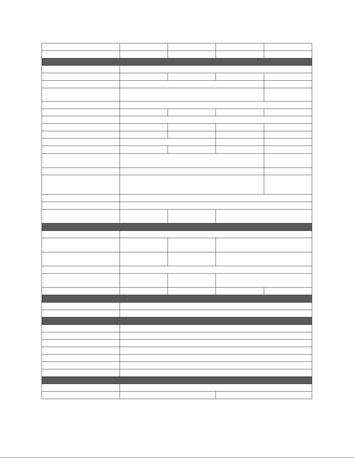
4.0 Specifications for BGB-series Belt Grinders
Model number
Stock number 577100 577125 577150 577153
Motor and Electricals
Motor type Totally enclosed fan cooled, induction
Horsepower 3/4 1 1-1/2 3
Phase 1 3
Voltage
Cycle 60 Hz
Listed FLA (full load amps) 11.5 / 5.8 12 / 6 14.6 / 7.3 8 / 4
Motor speed (RPM) 3450
Starting amps 36 48 52 42
Running amps (no load) 8 7.3 7 4
Start capacitor 200MFD 125VAC 400MFD 125VAC n/a
Run capacitor
Power cord
Power plug installed 125V, 15A n/a
On/off switch
Power transfer Poly V-belt
Recommended circuit size 2 20 Amp
Sound emission without load 3
Abrasive and wheels
Abrasive provided Aluminum oxide, 120-grit
Abrasive size
Abrasive speed 5500 FPM
Number of wheels 3
Wheel size Ø4.75 x 1 in.
Wheel speed (RPM) 4500 4600 4400 4400
Dust collection
Dust port outside diameter 2 in. (50.8 mm)
Recommended dust extraction 400 CFM (0.5 CMM)
Main materials
Housing Aluminum and steel
Motor shroud Steel
Platen Cast iron
Table Cast iron
Base Cast iron
Contact wheel Aluminum, rubber coated (65 Duro)
Driven wheels Aluminum, PU coated
Dimensions
Work rest (LxW) 2-1/4 x 4-1/2 in. (57 x 115 mm)
Base (LxW) 13-1/2 x 15-3/64 in. (343 x382mm) 13-1/2 x 17 in. (343 x 432 mm)
BGB-142 BGB-248 BGB-260-1 BGB-260-3
1
n/a
n/a
SJT 14AWG x 3C, 6 ft. (1830 mm) ST 14AWGx4C
74 dB at 100cm,
77 dB at 50cm
1 x 42 in.
(25 x 1067mm)
(1676 MPM)
(120 x 25 mm)
115/230V (prewired 115V) 230/460V
(prewired 230V)
45μF 250VAC 70μF 250VAC
in terminal box
Toggle with safety key Momentary, to
control magnetic
switch
80 dB at 100cm,
84 dB at 50cm
2 x 48 in.
(50 x 1219 mm)
6000 FPM
(1829 MPM)
Ø5 x 2 in.
(127 x 50 mm)
78 dB at 100cm,
82 dB at 50cm
2 x 60 in.
(50 x 1524 mm)
8000 FPM
(2438 MPM)
Ø7 x 2 in. (178 x 50 mm)
6

Dimensions (cont.)
Overall dimensions (HxWxD) 20-5/16 x 15-5/8
Shipping dimensions (HxWxD) 24-13/16 x 22-7/16 x 24-13/32 in.
Weights
Net weight (approx.) 105 lb. (48 kg) 114 lb. (52 kg) 137 lb. (62 kg) 145 lb. (66 kg)
Shipping weight (approx.) 124 lb. (56 kg) 132 lb. (60 kg) 161 lb. (72.8 kg) 168 lb. (76 kg)
BGB-142 BGB-248 BGB-260-1 BGB-260-3
x 20-17/3 in.
(516 x 397 x 521
mm)
(630 x 570 x 620 mm)
22-11/32 x 19 x
20-5/8 in.
(567 x 482 x 524
mm)
26-11/16 x 21 x 23-3/32 in.
(678 x 533 x 587 mm)
29-1/8 x 25-19/32 x 28-3/4 in.
(740 x 650 x 730 mm)
Table 4-1
1
Conversion to 460-volt requires purchase and installation of 460V magnetic contactor (not provi ded). See parts list.
2
Subject to local and national electrical codes.
3
The specified values are emission levels and are not necessarily to be seen as safe operating levels. As workplace
conditions vary, this information is intended to allow the user to make a better estimation of the hazards and risks
involved only.
L = length, W = width, H = height, D = depth
n/a = not applicable
The specifications in this manual were current at time of publication, but because of our policy of continuous
improvement, JET reserves the right to change specifications at any time and without prior notice, without incurring
obligations.
4.1 Base mounting pattern
Figure 4-1
A B C
BGB-142
BGB-248
BGB-260-1
BGB-260-3
Ø 7/16 in. (11m
Ø 7/16 in. (11mm)
Ø 7/16 in. (11mm)
Ø 7/16 in. (11mm)
12-19/32 in. (320m 13-3/8 in. (340mm)
12-19/32 in. (320mm)
12-19/32 in. (320mm)
12-19/32 in. (320mm)
13-3/8 in. (340mm)
14-31/32 in. (380mm)
14-31/32 in. (380mm)
Table 4-2
7

Read and understand all
assembly instructions before attempting
assembly and setup. Failure to comply may
cause serious injury.
5.0 Setup and assembly
5.1 Shipping contents
1 Belt Grinder with mounted abrasive
1 Operating instructions and parts manual
1 Product registration card
5.2 Unpacking and installing
The Grinder does not require assembly, only
mounting to a support, such as bench or table.
Inspect contents for shipping damage. Report
damage, if any, to your distributor. Do not discard
shipping materials until grinder is installed and
running properly.
Lift grinder out of carton along with plywood
platform. Remove platform and place grinder on a
sturdy table or workbench. Secure to workbench
with fasteners through the four holes in base. See
sect. 4.1 for hole spacings.
An optional adaptor plate (not included) is available
for mounting the grinder to the JET JDCS-505 Dust
Collection Stand. See your dealer or visit our
website for ordering information.
IMPORTANT: The abrasive belt has been detensioned for shipping. Belt must be properly
tensioned before operating grinder. See sect. 7.3.
5.3 Dust collection
It is recommended that a dust collection system be
used with this machine. Connect dust hose (not
provided) to the 2-inch port at back of grinder and
secure with clamp.
6.0 Electrical connections
Electrical connections must be
made by a qualified electrician in compliance
with all relevant codes. This machine must be
properly grounded to help prevent electrical
shock and possible fatal injury.
Before connecting to power source, be sure switch
is in off position.
It is recommended that the Belt Grinder be
connected to a dedicated 20 amp circuit with circuit
breaker or time-delay fuse marked “D”. Local
codes take precedence over recommendations.
6.1 GROUNDING INSTRUCTIONS
1. All Grounded, Cord-connected Tools:
In the event of a malfunction or breakdown,
grounding provides a path of least resistance for
electric current to reduce the risk of electric shock.
This tool is equipped with an electric cord having an
equipment-grounding conductor and a grounding
plug. The plug must be plugged into a matching
outlet that is properly installed and grounded in
accordance with all local codes and ordinances.
Do not modify the plug provided - if it will not fit the
outlet, have the proper outlet installed by a qualified
electrician.
Improper connection of the equipment-grounding
conductor can result in a risk of electric shock. The
conductor with insulation having an outer surface
that is green with or without yellow stripes is the
equipment-grounding conductor. If repair or
replacement of the electric cord or plug is
necessary, do not connect the equipment-grounding
conductor to a live terminal.
Check with a qualified
electrician or service personnel if the grounding
instructions are not completely understood, or if
in doubt as to whether the tool is properly
grounded. Failure to comply may cause ser ious
or fatal injury.
Use only 3-wire extension cords that have 3-prong
grounding plugs and 3-pole receptacles that accept
the tool's plug.
Repair or replace damaged or worn cord
immediately.
2. Grounded, cord-connected tools intended for use
on a supply circuit having a nominal rating less than
150 volts:
This tool is intended for use on a circuit that has an
outlet that looks like the one illustrated in A, Figure
6-1. An adapter, shown in B and C, may be used to
connect this plug to a 2-pole receptacle as shown in
B if a properly grounded outlet is not available. The
temporary adapter should be used only until a
properly grounded outlet can be installed by a
qualified electrician. This adapter is not permitted in
Canada. The green-colored rigid ear, lug, and the
like, extending from the adapter must be connected
to a permanent ground such as a properly grounded
outlet box.
3. Grounded, cord-connected tools intended for use
on a supply circuit having a nominal rating between
150 - 250 volts, inclusive:
This tool is intended for use on a circuit that has an
outlet that looks like the one illustrated in D, Figure
6-1. The tool has a grounding plug that looks like the
plug illustrated in D. Make sure the tool is connected
to an outlet having the same configuration as the
plug. No adapter is available or should be used with
this tool.
8

If the tool must be reconnected for use on a different
type of electric circuit, the reconnection should be
made by qualified service personnel; and after
reconnection, the tool should comply with all local
codes and ordinances.
Figure 6-1
6.2 Voltage conversion
For models BGB-142, BGB-248, BGB-260-1:
1. Remove four screws from control panel, and
remove panel from motor shroud. Switch
incoming motor leads according to wiring
diagram.
2. Reinstall control panel on motor shroud.
3. Replace plug on end of motor cord with proper
UL/CSA listed plug rated for the new incoming
voltage.
4. Test run the grinder. If abrasive belt moves
upward instead of downward, disconnect
machine from power and switch any two of the
three power leads (not the green ground wire).
For model BGB-260-3:
1. Remove four screws from motor shroud and
remove shroud.
2. Open motor junction box and switch incoming
power leads according to wiring diagram on
inside cover of junction box. Diagrams are also
placed at back of this manual. (In case of
discrepancy, diagrams on machine take
precedence.)
3. Replace magnetic starter with 460V starter; see
parts list to order.
4. Re-install junction box cover and motor shroud.
5. Test run the grinder. If abrasive belt moves
upward instead of downward, disconnect
machine from power and switch any two of the
three power leads (not the green ground wire).
6.3 Extension cords
The use of extension cords is discouraged; try to
position equipment within reach of the power
source. For circuits which are far away from the
electrical service box, the wire size must be
increased in order to deliver ample voltage to the
motor. To minimize power losses and to prevent
motor overheating and burnout, the use of wire sizes
for branch circuits or electrical extension cords
according to Table 1 is recommended. If in doubt,
use the next heavier gauge. The smaller the gauge
number, the heavier the cord.
Conductor
length
0 – 50 ft. 14 14
50 – 100 ft. 14 12
Over 100 ft. 14 8
AWG # (American Wire Gauge)
240 Volt lines 120 Volt lines
Extension Cord Recommendations
Table 6-1
9

Figure 7-1: Belt Grinder identification
7.0 Adjustments
Disconnect machine from
power source before making adjustments.
Refer to Figure 7-1.
7.1 Work rest adjustment
Loosen work rest handle and adjust work rest to
desired angle. Minimize gap between edge of work
rest and abrasive belt; 1/16-inch or less.
Tighten work rest handle before operating.
Note: Handles are adjustable; pull handle straight
out and rotate it on the pin, then release. Make sure
handle reseats itself on the pin.
7.2 Platen adjustment
Loosen platen handle and adjust platen so it is
parallel to back of abrasive belt and almost touching.
7.3 Abrasive belt tension
To de-tension abrasive belt, turn tension knob
counterclockwise and pull knob to the right.
To tension, push knob to the left. The pawl will “click”
as it engages each ratchet tooth. Do not
overtension; tighten belt until it is just taut. A
moderate tension will provide faster cutting and
longer belt life, as well as better tracking.
NOTE: When belt grinder is not being used, detension the abrasive belt. This will prolong the li fe of
the belt, and reduce load on wheels, bearings and
other components.
7.4 Abrasive belt tracking
The abrasive belt should remain centered upon the
wheels during operation. If it tends to slide offcenter, adjust as follows:
1. Disconnect machine from power source and
pull open side cover.
10

2. Rotate tracking knob left or right as you turn
tracking wheel with your other hand. Do this in
small increments and allow time for belt to
respond to changes. Clockwise knob rotation
moves belt toward left, counterclockwise toward
right.
3. If belt refuses to track properly, increase belt
tension and repeat above steps.
7.5 V-belt tension
1. Disconnect machine from power source.
2. Remove four button head screws and open
motor shroud.
3. Remove two screws from pulley cover (access
through housing) and remove pulley cover.
4. Loosen screws on motor mount and slide motor
backward to tension belt.
5. Tighten motor mount screws, reinstall pulley
cover and shroud.
3. Handles must be tight and covers closed
before operating.
4. Some metals may create a fire hazard during
grinding; consult workpiece supplier for
instructions on proper use and cautions.
5. Allow machine to come up to speed before
applying workpiece.
6. Place workpiece upon work rest, and apply
only moderate pressure into abrasive belt; do
not apply excessive pressure.
9.0 User-maintenance
Always disconnect power to
machine before performing maintenance.
Failure to do this may result in serious personal
injury.
9.1 General cleaning
8.0 Operation
8.1 Operating controls
Refer to Figure 7-1.
Power indicator light – Illuminates when machine
is connected to power.
Running indicator light – Illuminates when motor
is operating.
MODELS BGB-142/248/260-1 only:
On/off switch with safety key – Pull up to start
motor, push down to stop.
IMPORTANT: To prevent accidental or
unauthorized starting of grinder, shut off machine
and pull out key (yellow portion) of switch and store
in safe place. This key must be reinserted to start
machine.
Overload reset – If motor overheats, allow machine
a few minutes to cool down, then push button to
reset.
MODELS BGB-260-3 only:
On button – Push to start motor.
Emergency stop – Push to stop motor. To restart,
rotate button clockwise until it disengages.
Overload reset – (Inside magnetic starter box.) If
motor overheats, allow machine a few minutes to
cool down, then the overload relay will automatically
reset.
8.2 General operating tips
1. Always use platen when grinding workpiece.
2. Adjust gap between work rest and belt to 1/16inch or less.
Keep exterior of machine clean and free of chips.
Periodically clean out interior of housing with
vacuum or brush – do not use bare hands.
Periodically empty grinding dust and particles from
the dust collection system (not provided).
9.2 Lubrication
Lubrication of the grinder is not required. Bearings
are pre-lubricated and sealed.
9.3 Abrasive belt replacement
1. Disconnect machine from power source.
2. Open side cover, and open dust cover by
unscrewing dust cover screw.
3. De-tension and slip belt off wheels.
4. Install new belt around wheels, tension, and
test tracking. Make further adjustments as
needed.
5. Close all covers before operating.
9.4 Contact wheel replacement
1. Disconnect machine from power source.
2. Open side cover and dust cover, and remove
abrasive belt.
3. Loosen and remove hex nut and flange
washer, and slide contact wheel off spindle.
4. Install new wheel. Reinstall flange washer and
hex nut and tighten.
5. Install abrasive belt, tension, and check
tracking.
6. Close all covers before operating.
11

9.5 V-belt replacement
10.0 Optional accessories
Disconnect machine from power source. Follow
steps in sect. 7.4 to access pulleys and belt. Slide
motor forward to loosen belt and slip belt off pulleys.
Install new belt and slide motor back to tension it.
Secure all covers and screws.
The following adaptor plates are available for
mounting your grinder to the JDCS-505 JET Dust
Collection Stand. Contact your dealer to order, or
call JET at the phone number on the cover.
# 414832 – Adaptor Plate Kit (for BGB-142/248)
9.6 Additional servicing
Any additional servicing should be performed by
authorized service personnel.
# 414833 – Adaptor Plate Kit (for BGB-260-1/260-3)
11.0 Troubleshooting BG B-series Belt Grinders
Symptom Possible Cause Correction*
Motor will not start Low voltage. Check power line for proper voltage.
Open circuit in motor or loose
connection.
Motor will not start: fuses
or circuit breakers blow
Machine slows when
operating
Loud, repetitive noise
coming from machine
Poor tracking Improper abrasive belt splice. Check belt for irregular seam or shape.
Slack abrasive belt Insufficient belt tension. Set tension so belt is just taut.
Short circuit in line cord or plug. Inspect cord or plug for damaged insulation
Short circuit in motor or loose
connections.
Incorrect fuses or circuit breakers in
power line.
Applying excessive pressure of
workpiece against platen.
V-belt loose. Tighten V-belt.
Pulley setscrews or keys are missin g or
loose.
Motor fan is hitting the fan cover. Tighten fan or shim cover.
V-belt is defective. Replace V-belt.
Excessive belt tension. Set tension so belt is just taut.
Insufficient belt tension. Set tension so belt is just taut.
Worn contact surfaces. Check surface of contact wheels. Replace
Misaligned contact surfaces. Check alignment of tracking wheels and
Lack of crown on drive wheel. Check for 1/16-inch crown. Replace drive
Worn bearings. Check all bearings for overheating or
Inspect all lead connections on motor for
loose or open connections.
and shorted wires.
Inspect all connections on motor for loose or
shorted terminals or worn insulation.
Install correct fuses or circuit breakers.
Reduce pressure against abrasive/platen.
Inspect keys and setscrews. Replace or
tighten if necessary.
worn wheels.
contact wheel. Realign if needed.
wheel if crown is not present.
damage. Replace w orn or damaged bearings.
Contact wheel wear Excessive belt tension. Set tension so belt is just taut.
Grinding in one area on belt. Use entire work surface of belt whenev er
possible.
Excessive grinding depos its o n be lt and
debris in machine.
Short abrasive belt life. Excessive grinding pressure. Allow belt to do the cutting. Excessive
Periodically clean interior of grinder.
pressure dulls belt and removes grit from it.
*Warning: Some corrections may require a qualified electrician.
Table 11-1
12

12.0 Replacement Parts
Replacement parts are listed on the following pages. To order parts or reach our service department, call 1-800274-6848 Monday through Friday, 8:00 a.m. to 5:00 p.m. CST. Having the Model Number and Serial Number of
your machine available when you call will allow us to serve you quickly and accurately.
Non-proprietary parts, such as fasteners, can be found at local hardware stores, or may be ordered from JET.
Some parts are shown for reference only, and may not be available individually.
12.1.1 Motor and Base Assembly – Exploded View - Models BGB-142/248/260-1
13

12.1.2 Motor and Base Assembly – Parts List – Model BGB-142
Index No Part No Description Size Qty
1 ................ BGB248-101 ............. Switch Box ............................................................... ...................................... 1
2 ................ 6295815 .................... Phillips Round Hd Tapping Screw ........................... M3 x 10L ....................... 8
3 ................ BGB248-103 ............. Strain Relief ............................................................. ...................................... 1
4 ................ BGB248-104 ............. Cable Protection Pipe .............................................. ...................................... 1
5 ................ BGB248-105 ............. Strain Relief ............................................................. ...................................... 1
6 ................ F009887 .................... Socket Head Button Screw ...................................... M5 x 0.8P x 16L ........... 2
7 ................ JSG96-135 ................ Switch ...................................................................... ...................................... 1
.................. JSG96-135A .............. Switch Key (not shown) ........................................... ...................................... 1
8 ................ BGB248-108 ............. Control Panel (includes LM000254 label) ................ ...................................... 1
9 ................ BGB248-109 ............. Overload Protector................................................... ...................................... 1
10 .............. BGB248-110 ............. Running Indication Light .......................................... ...................................... 1
11 .............. BGB248-111 ............. Power Indication Light ............................................. ...................................... 1
12 .............. F000648 .................... Phillips Pan Hd Machine Screw ............................... #10-24UNC x 1/4"L ....... 2
13 .............. F002097 .................... Lock Washer, Ext. Tooth ......................................... M5 ................................. 2
14 .............. BGB248-114 ............. Copper Ground Plate ............................................... ...................................... 1
15 .............. BGB248-115 ............. Motor Shroud ........................................................... ...................................... 1
16 .............. BGB248-116 ............. Strain Relief ............................................................. ...................................... 1
17 .............. TS-2248122 .............. Socket Head Button Screw ...................................... M8 x 1.25 x 12L ............ 4
18 .............. TS-1550061 .............. Flat Washer ............................................................. 8.5 x 20 x 1.5T .............. 8
19 .............. JET-138 ..................... JET Logo ................................................................. 138 x 57mm .................. 1
20 .............. BGB142-120 ............. Motor ....................................................................... 3/4HP, 115/230V, 1PH . 1
.................. BGB248-120SC ........ Starting Capacitor (not shown) ................................ 200MFD 125VAC .......... 1
.................. BGB248-120SCC ...... Starting Capacitor Cover (not shown)...................... ...................................... 1
.................. BGB248-120CF ......... Cooling Fan (not shown) ......................................... ...................................... 1
.................. BGB248-120FC ......... Fan Cover (not shown) ............................................ ...................................... 1
21 .............. TS-2228161 .............. Hex Cap Screw ........................................................ M8 x 1.25P x 16L ......... 4
22 .............. TS-2361081 .............. Lock Washer ............................................................ M8 ................................. 4
23 .............. BGB142-123 ............. Base......................................................................... ...................................... 1
24 .............. 6296048 .................... Key, Double Rd Head .............................................. 5 x 5 x 25L mm ............. 1
25 .............. TS-1522021 .............. Socket Head Set Screw ........................................... M5-0.8 x 8L ................... 2
26 .............. BGB142-126 ............. Motor Pulley ............................................................. ...................................... 1
27 .............. BGB248-127 ............. Power Cable ............................................................ ...................................... 1
28 .............. BGB248-128 ............. Internal Cable .......................................................... 14AWG, 20cm, Black .... 2
29 .............. BGB248-129 ............. Internal Cable .......................................................... 14AWG, 20cm, White ... 2
30 .............. BGB248-130 ............. Internal Cable .......................................................... 14AWG, 50cm, Black .... 4
31 .............. BGB248-131 ............. Internal Cable .......................................................... 14AWG, 60cm, Green .. 1
32 .............. BGB248-132 ............. Internal Cable .......................................................... 14AWG, 10cm, Red ...... 2
33 .............. BGB248-133 ............. Internal Cable .......................................................... 14AWG, 10cm, White ... 1
34 .............. BGB248-134 ............. Internal Cable .......................................................... 18AWG, 15cm, White ... 1
35 .............. BGB248-135 ............. Internal Cable .......................................................... 14AWG, 12cm, Black .... 1
36 .............. BGB248-136 ............. Internal Cable .......................................................... 18AWG, 10cm, Red ...... 1
37 .............. BGB248-137 ............. Wire Nut ................................................................... ...... ................................ 5
14

12.1.3 Motor and Base Assembly – Parts List – Model BGB-248
Index No Part No Description Size Qty
1 ................ BGB248-101 ............. Switch Box ............................................................... ...................................... 1
2 ................ 6295815 .................... Phillips Round Hd Tapping Screw ........................... M3 x 10L ....................... 8
3 ................ BGB248-103 ............. Strain Relief ............................................................. ...................................... 1
4 ................ BGB248-104 ............. Cable Protection Pipe .............................................. ...................................... 1
5 ................ BGB248-105 ............. Strain Relief ............................................................. ...................................... 1
6 ................ F009887 .................... Socket Head Button Screw ...................................... M5 x 0.8P x 16L ........... 2
7 ................ JSG96-135 ................ Switch ...................................................................... ...................................... 1
.................. JSG96-135A .............. Switch Key (not shown) ........................................... ...................................... 1
8 ................ BGB248-108 ............. Control Panel (includes LM000254 label) ................ ...................................... 1
9 ................ BGB248-109 ............. Overload Protector................................................... ...................................... 1
10 .............. BGB248-110 ............. Running Indication Light .......................................... ...................................... 1
11 .............. BGB248-111 ............. Power Indication Light ............................................. ...................................... 1
12 .............. F000648 .................... Phillips Pan Hd Machine Screw ............................... #10-24UNC x 1/4"L ....... 2
13 .............. F002097 .................... Lock Washer, Ext. Tooth ......................................... M5 ................................. 2
14 .............. BGB248-114 ............. Copper Ground Plate ............................................... ...................................... 1
15 .............. BGB248-115 ............. Motor Shroud ........................................................... ...................................... 1
16 .............. BGB248-116 ............. Strain Relief ............................................................. ...................................... 1
17 .............. TS-2248122 .............. Socket Head Button Screw ...................................... M8 x 1.25 x 12L ............ 4
18 .............. TS-1550061 .............. Flat Washer ............................................................. 8.5 x 20 x 1.5T .............. 8
19 .............. JET-138 ..................... JET Logo ................................................................. 138 x 57mm .................. 1
20 .............. BGB248-120 ............. Motor ....................................................................... 1HP, 115/230V, 1Ph ..... 1
.................. BGB248-120SC ........ Starting Capacitor (not shown) ................................ 200MFD 125VAC .......... 1
.................. BGB248-120SCC ...... Starting Capacitor Cover (not shown)...................... ...................................... 1
.................. BGB248-120RC ........ Running Capacitor (not shown) ............................... 45μF 250VAC ............... 1
.................. BGB248-120RCC ...... Running Capacitor Cover (not shown)..................... ...................................... 1
.................. BGB248-120CF ......... Cooling Fan (not shown) ......................................... ...................................... 1
.................. BGB248-120FC ......... Fan Cover (not shown) ............................................ ...................................... 1
21 .............. TS-2228161 .............. Hex Cap Screw ........................................................ M8 x 1.25P x 16L ......... 4
22 .............. TS-2361081 .............. Lock Washer ............................................................ M8 ................................. 4
23 .............. BGB248-123 ............. Base......................................................................... ...................................... 1
24 .............. 6296048 .................... Key, Double Rd Head .............................................. 5 x 5 x 25L mm ............. 1
25 .............. TS-1522021 .............. Socket Head Set Screw ........................................... M5-0.8 x 8L ................... 2
26 .............. BGB248-126 ............. Motor Pulley ............................................................. ...................................... 1
27 .............. BGB248-127 ............. Power Cable ............................................................ ...................................... 1
28 .............. BGB248-128 ............. Internal Cable .......................................................... 14AWG, 20cm, Black .... 2
29 .............. BGB248-129 ............. Internal Cable .......................................................... 14AWG, 20cm, White ... 2
30 .............. BGB248-130 ............. Internal Cable .......................................................... 14AWG, 50cm, Black .... 4
31 .............. BGB248-131 ............. Internal Cable .......................................................... 14AWG, 60cm, Green .. 1
32 .............. BGB248-132 ............. Internal Cable .......................................................... 14AWG, 10cm, Red ...... 2
33 .............. BGB248-133 ............. Internal Cable .......................................................... 14AWG, 10cm, White ... 1
34 .............. BGB248-134 ............. Internal Cable .......................................................... 18AWG, 15cm, White ... 1
35 .............. BGB248-135 ............. Internal Cable .......................................................... 14AWG, 12cm, Black .... 1
36 .............. BGB248-136 ............. Internal Cable .......................................................... 18AWG, 10cm, Red ...... 1
37 .............. BGB248-137 ............. Wiring Nut ................................................................ ...................................... 5
15

12.1.4 Motor and Base Assembly – Parts List – Model BGB-260-1
Index No Part No Description Size Qty
1 ................ BGB248-101 ............. Switch Box ............................................................... ...................................... 1
2 ................ 6295815 .................... Phillips Round Hd Tapping Screw ........................... M3 x 10L ....................... 8
3 ................ BGB248-103 ............. Strain Relief ............................................................. ...................................... 1
4 ................ BGB248-104 ............. Cable Protection Pipe .............................................. ...................................... 1
5 ................ BGB248-105 ............. Strain Relief ............................................................. ...................................... 1
6 ................ F009887 .................... Socket Head Button Screw ...................................... M5 x 0.8P x 16L ........... 2
7 ................ JSG96-135 ................ Switch ...................................................................... ...................................... 1
.................. JSG96-135A .............. Switch Key (not shown) ........................................... ...................................... 1
8 ................ BGB248-108 ............. Control Panel (includes LM000254 label) ................ ...................................... 1
9 ................ BGB260-1-109 .......... Overload Protector................................................... ...................................... 1
10 .............. BGB248-110 ............. Running Indication Light .......................................... ...................................... 1
11 .............. BGB248-111 ............. Power Indication Light ............................................. ...................................... 1
12 .............. F000648 .................... Phillips Pan Hd Machine Screw ............................... #10-24UNC x 1/4"L ....... 2
13 .............. F002097 .................... Lock Washer, Ext. Tooth ......................................... M5 ................................. 2
14 .............. BGB248-114 ............. Copper Ground Plate ............................................... ...................................... 1
15 .............. BGB260-1-115 .......... Motor Shroud ........................................................... ...................................... 1
16 .............. BGB248-116 ............. Strain Relief ............................................................. ...................................... 1
17 .............. TS-2248122 .............. Socket Head Button Screw ...................................... M8 x 1.25 x 12L ............ 4
18 .............. TS-1550061 .............. Flat Washer ............................................................. 8.5 x 20 x 1.5T .............. 8
19 .............. JET-138 ..................... JET Logo ................................................................. 138 x 57mm .................. 1
20 .............. BGB260-1-120 .......... Motor ....................................................................... 1-1/2HP,115/230V,1Ph . 1
.................. BGB260-1-120SC ..... Starting Capacitor (not shown) ................................ 450MFD 125VAC .......... 1
.................. BGB260-1-120SCC ... Starting Capacitor Cover (not shown)...................... ...................................... 1
.................. BGB248-120RC ........ Running Capacitor (not shown) ............................... 70μF 250VAC ............... 1
.................. BGB248-120RCC ...... Running Capacitor Cover (not shown)..................... ...................................... 1
.................. BGB248-120CF ......... Cooling Fan (not shown) ......................................... ...................................... 1
.................. BGB248-120FC ......... Fan Cover (not shown) ............................................ ...................................... 1
21 .............. TS-2228161 .............. Hex Cap Screw ........................................................ M8 x 1.25P x 16L ......... 4
22 .............. TS-2361081 .............. Lock Washer ............................................................ M8 ................................. 4
23 .............. BGB260-1-123 .......... Base......................................................................... ...................................... 1
24 .............. 6296048 .................... Key, Double Rd Head .............................................. 5 x 5 x 25L mm ............. 1
25 .............. TS-1522021 .............. Socket Head Set Screw ........................................... M5-0.8 x 8L ................... 2
26 .............. BGB260-1-126 .......... Motor Pulley ............................................................. ...................................... 1
27 .............. BGB248-127 ............. Power Cable ............................................................ ...................................... 1
28 .............. BGB248-128 ............. Internal Cable .......................................................... 14AWG, 20cm, Black .... 2
29 .............. BGB248-129 ............. Internal Cable .......................................................... 14AWG, 20cm, White ... 2
30 .............. BGB248-130 ............. Internal Cable .......................................................... 14AWG, 50cm, Black .... 4
31 .............. BGB248-131 ............. Internal Cable .......................................................... 14AWG, 60cm, Green .. 1
32 .............. BGB248-132 ............. Internal Cable .......................................................... 14AWG, 10cm, Red ...... 2
33 .............. BGB248-133 ............. Internal Cable .......................................................... 14AWG, 10cm, White ... 1
34 .............. BGB248-134 ............. Internal Cable .......................................................... 18AWG, 15cm, White ... 1
35 .............. BGB248-135 ............. Internal Cable .......................................................... 14AWG, 12cm, Black .... 1
36 .............. BGB248-136 ............. Internal Cable .......................................................... 18AWG, 10cm, Red ...... 1
37 .............. BGB248-137 ............. Wiring Nut ................................................................ ...................................... 5
16

12.2.1 Motor and Base Assembly – Exploded View – Model BGB-260-3
17

12.2.2 Motor and Base Assembly – Parts List – Model BGB-260-3
Index No Part No Description Size Qty
1 ................ BGB260-3-101 .......... Switch Box ............................................................... ...................................... 1
2 ................ 6295815 .................... Phillips Round Hd Tapping Screw ........................... M3 x 10L ....................... 8
3 ................ BGB248-103 ............. Strain Relief ............................................................. ...................................... 2
4 ................ BGB248-104 ............. Cable Protection Pipe .............................................. ...................................... 1
5 ................ F009887 .................... Socket Head Button Screw ...................................... M5 x 0.8P x 16L ........... 2
6 ................ BGB260-3-106 .......... Control Panel (includes LM000261 label) ................ ...................................... 1
7 ................ BGB260-3-107 .......... ON Switch ................................................................ ...................................... 1
8 ................ BGB260-3-108 .......... Emergency Stop ...................................................... ............. ......................... 1
9 ................ BGB260-3-109 .......... Running Indication Light .......................................... ...................................... 1
10 .............. BGB260-3-110 .......... Power Indication Light ............................................. ...................................... 1
11 .............. BGB260-3-111 .......... Magnetic Switch Assembly ...................................... 230V, 3PH .................... 1
.................. BGB260-3-111C ........ Contactor ................................................................. ...................................... 1
.................. BGB260-3-111O ....... Overload Relay ........................................................ ...................................... 1
.................. BGB260-3-111A ........ Magnetic Switch Assembly ...................................... 460V, 3PH .................... 1
.................. BGB260-3-111AC ..... Contactor ................................................................. ...................................... 1
.................. BGB260-3-111AO ..... Overload Relay ........................................................ ...................................... 1
12 .............. TS-2284082 .............. Phillips Pan Hd Machine Screw ............................... M4 x 0.7P x 8L .............. 3
13 .............. BGB260-3-113 .......... Strain Relief ............................................................. ........ .............................. 3
14 .............. BGB260-3-114 .......... Switch Plate ............................................................. ...................................... 1
15 .............. TS-2331041 .............. Cap Nut.................................................................... M4 x 0.7P ...................... 3
16 .............. BGB260-3-116 .......... Motor Shroud ........................................................... ...................................... 1
17 .............. TS-1550031 .............. Flat Washer ............................................................. 5.1 x 12 x 1T ................. 4
18 .............. TS-1533032 .............. Phillips Pan Hd Machine Screw ............................... M5 x 0.8P x 10L ............ 7
19 .............. BGB260-3-119 .......... Strain Relief ............................................................. ........ .............................. 1
20 .............. BGB260-3-120 .......... Terminal Box............................................................ ...................................... 1
21 .............. F002097 .................... Lock Washer, Ext. Tooth ......................................... M5 ................................ 4
22 .............. TS-2248122 .............. Socket Head Button Screw ...................................... M8 x 1.25 x 12L ........... 5
23 .............. TS-1550061 .............. Flat Washer ............................................................. 8.5 x 20 x 1.5T ............ 10
24 .............. JET-138 ..................... JET Logo ................................................................. 138 x 57mm .................. 1
25 .............. BGB260-3-125 .......... Motor........................................................................ 3HP, 230V/460, 3PH .... 1
.................. BGB248-120CF ......... Cooling Fan (not shown) ......................................... ...................................... 1
.................. BGB248-120FC ......... Fan Cover (not shown) ............................................ ...................................... 1
26 .............. TS-2228161 .............. Hex Cap Screw ........................................................ M8 x 1.25P x 16L .......... 4
27 .............. TS-2361081 .............. Lock Washer ............................................................ M8 ................................. 4
28 .............. BGB260-1-123 .......... Base......................................................................... ...................................... 1
29 .............. 6296048 .................... Key, Double Rd Head .............................................. 5 x 5 x 25L mm ............. 1
30 .............. TS-1522021 .............. Socket Head Set Screw ........................................... M5 x 0.8P x 8L ............. 2
31 .............. BGB260-1-126 .......... Pulley ....................................................................... ...................................... 1
32 .............. BGB260-3-132 .......... Power Cable ............................................................ ...................................... 1
33 .............. BGB260-3-133 .......... Motor Cable ............................................................. ...................................... 1
34 .............. BGB260-3-134 .......... Internal Cable Set .................................................... 18AWG, 80cm, 3C ........ 1
35 .............. BGB260-3-135 .......... Internal Cable Set .................................................... 18AWG, 80cm, 2C ........ 1
36 .............. BGB248-136 ............. Internal Cable .......................................................... 18AWG, 10cm, Red ...... 1
37 .............. BGB260-3-137 .......... Internal Cable .......................................................... 18AWG, 20cm, Black .... 1
38 .............. BGB260-3-138 .......... Internal Cable .......................................................... 18AWG, 5cm, Black ...... 1
18

12.3.1 Belt and Housing Assembly – Exploded View – Model BGB-142
4
5
6
7
8
9
10
11
83
13
14
83
20
24
11
E
31
30
54
55
30
C
57
58
32
25
D
B
7
29
7
38
47
48
43
42
44
30
31
45
46
7
33
57
34
31
B
51
52
53
35
36
58
37
49
40
50
11
12
2
C
1
3
15
16
18
41
40
27
21
19
22
23
16
26
8
28
5
36
8
39
12
17
8
36
56
31
30
19
59
60
62
63
61
D
7
33
73
74
70
65
E
75
79
64
76
77
78
69
66
67
68
16
69
70
80
69
71
81
72
82
11
83
13
14
83
11
19

12.3.2 Belt and Housing Assembly – Parts List – Model BGB-142
Index No Part No Description Size Qty
1 ................ BGB248-201 ............. Compression Spring ................................................ ...................................... 1
2 ................ TS-1502031 .............. Socket Head Cap Screw ......................................... M5-0.8P x 12L ............. 2
3 ................ BGB248-203 ............. Supporting Plate ...................................................... ...................................... 1
4 ................ TS-1541031 .............. Hex Nut, Nylon Lock ................................................ M8-1.25P ..................... 1
5 ................ TS-1550061 .............. Flat Washer ............................................................. 8.5 x 19 x 2T ................. 2
6 ................ BGB248-206 ............. Fixed Bracket ........................................................... ........ .............................. 1
7 ................ TS-2361061 .............. Lock Washer ............................................................ M6 ............................. 12
8 ................ TS-1503061 .............. Socket Head Cap Screw ......................................... M6-0.8P x 25L ............. 7
9 ................ BGB248-209 ............. Pivoting Shaft .......................................................... ........ .............................. 1
10 .............. BGB248-210 ............. Tracking Wheel Hub ................................................ ...................................... 1
11 .............. 6292752 .................... Ext. Retaining Ring .................................................. STW-15 ......................... 6
12 .............. BB-6202ZZ ................ Ball Bearing ............................................................. 6202 ZZ ........................ 2
13 .............. BGB142-213 ............. Tracking Wheel Axle ................................................ ...................................... 2
14 .............. BGB142-214 ............. Tracking Wheel ........................................................ ...................................... 2
15 .............. 5509829 .................... Roll Pin .................................................................... 6 x 36L mm .................. 1
16 .............. TS-1523021 .............. Socket Head Set Screw ........................................... M6-1.0P x 8L ............... 3
17 .............. BGB248-217 ............. Pulley Cover ............................................................ ...................................... 1
18 .............. BGB248-218 ............. Pulley Cover Rear Plate .......................................... ...................................... 1
19 .............. TS-1550031 .............. Flat Washer ............................................................. 5.1 x 12 x 1T ................. 4
20 .............. TS-1533032 .............. Phillips Pan Hd Machine Screw ............................... M5-0.8P x 10L ............. 2
21 .............. BGB248-221 ............. Poly V-Belt ............................................................... ...................................... 1
22 .............. BGB248-222 ............. Knob ........................................................................ ...................................... 1
23 .............. F010433 .................... Socket Head Set Screw ........................................... M8-1.25P x 40L ........... 1
24 .............. BGB142-224 ............. Housing.................................................................... ...................................... 1
25 .............. TS-1541031 .............. Hex Nut .................................................................... M8-1.25P ...................... 1
26 .............. BGB142-226 ............. Spindle Pulley .......................................................... ...................................... 1
27 .............. BGB248-227 ............. Knob Screw ............................................................. ...................................... 1
28 .............. BGB142-228 ............. Dust Cover ............................................................... ........ .............................. 1
29 .............. BGB248-229 ............. Hinge ....................................................................... ...................................... 1
30 .............. TS-2361051 .............. Lock Washer ............................................................ M5 ............................... 12
31 .............. TS-2245102 .............. Socket Head Button Screw ...................................... M5-0.8P x 10L ............. 9
32 .............. BGB248-232 ............. Ratchet .................................................................... ...................................... 1
33 .............. TS-1503041 .............. Socket Head Cap Screw ......................................... M6-1.0P x 16L ............. 5
34 .............. BGB248-234 ............. Clip........................................................................... ...................................... 2
35 .............. BGB142-235 ............. Spine Central Guard ................................................ ...................................... 1
36 .............. TS-1550041 .............. Flat Washer ............................................................. 6 x 12 x 1T mm ............. 5
37 .............. TS-1503021 .............. Socket Head Cap Screw ......................................... M6-1.0P x 10L ............. 3
38 .............. TS-1503131 .............. Socket Head Cap Screw ......................................... M6-1.0P x 60L ............. 2
39 .............. BGB248-239 ............. Bearing Housing ...................................................... ...................................... 1
40 .............. BGB248-240 ............. Universal Handle ..................................................... ...................................... 2
41 .............. BGB248-241 ............. Table Support Arm................................................... ...................................... 1
42 .............. BGB142-242 ............. Platen....................................................................... ...................................... 1
43 .............. BGB142-243 ............. Contact Wheel Cover............................................... ...................................... 1
44 .............. 6296048 .................... Key, Double Rd Head .............................................. 5 x 5 x 25L mm ............. 1
45 .............. BGB142-245 ............. Contact Wheel Spindle ............................................ ...................................... 1
46 .............. BGB142-246 ............. Contact Wheel ......................................................... ...................................... 1
47 .............. BGB248-247 ............. Flange Washer ........................................................ ...................................... 1
48 .............. TS-0561071 .............. Hex Nut .................................................................... 5/8"-11UNC .................. 1
49 .............. TS-1550061 .............. Flat Washer ............................................................. 8 x 30 x 3T mm ............. 1
50 .............. BGB248-250 ............. Work Rest ............................................................... ...................................... 1
51 .............. TS-1492011 .............. Hex Cap Screw ........................................................ M12-1.75P x 25L ......... 4
52 .............. TS-2361121 .............. Lock Washer ............................................................ M12 ............................. 4
53 .............. TS-155009 ................ Flat Washer ............................................................. 13.5 x 28 x 3T mm ........ 4
54 .............. BGB248-254 ............. Continuous Hinge .................................................... ...................................... 1
55 .............. F009887 .................... Socket Head Button Screw ...................................... M5-0.8P x 16L ............. 3
56 .............. BGB142-256 ............. Side Cover ............................................................... ...................................... 1
57 .............. BGB248-257 ............. Peg .......................................................................... ...................................... 2
58 .............. TS-1540041 .............. Hex Nut .................................................................... M6-1.0P ....................... 2
59 .............. BGB248-259 ............. Door Latch ............................................................... ...................................... 1
60 .............. BGB142-260 ............. Abrasive Belt............................................................ 1”Wx42”L 120G ............ 1
20

Index No Part No Description Size Qty
61 .............. BGB248-261 ............. Knob ........................................................................ ...................................... 1
62 .............. F010391 .................... Socket Head Set Screw ........................................... M5 x 0.8P x 5L ............. 1
63 .............. BGB248-263 ............. Hub Supporting Shaft .............................................. ...................................... 1
64 .............. BGB248-264 ............. Rod .......................................................................... ...................................... 1
65 .............. TS-1532052 .............. Phillips Pan Hd Machine Screw ............................... M4 x 0.7P x 16L ........... 1
66 .............. BGB248-266 ............. Tension Spring ........................................................ ...................................... 1
67 .............. TS-1540021 .............. Hex Nut .................................................................... M4-0.7P ....................... 1
68 .............. BGB248-268 ............. Tension Wheel Arm ................................................. ...................................... 1
69 .............. TS-1550041 .............. Flat Washer ............................................................. 6.4 x 16 x 1.6T mm ....... 4
70 .............. TS-1541021 .............. Hex Nut, Nylon Lock ................................................ M6-1.0P ....................... 2
71 .............. BGB248-271 ............. Spring Tension Adj. Rod .......................................... ...................................... 1
72 .............. TS-134608 ................ Phillips Flat Hd Machine Screw ............................... 1/4"-20UNC x 1-1/4"L .. 1
73 .............. F012091 .................... Roll Pin .................................................................... 3 x 10L mm .................. 1
74 .............. BGB248-274 ............. Rivet......................................................................... .... .................................. 1
75 .............. BGB248-275 ............. Pawl ......................................................................... ...................................... 1
76 .............. F012092 .................... Roll Pin .................................................................... 3 x 18L mm .................. 1
77 .............. TS-0570011 .............. Hex Nut .................................................................... 1/4"-20UNC .................. 1
78 .............. BGB248-278 ............. Oilite Washer ........................................................... ...................................... 1
79 .............. BGB248-279 ............. Compression Spring ................................................ ...................................... 1
80 .............. BGB248-280 ............. Tension Wheel Hub ................................................. ...................................... 1
81 .............. TS-1550071 .............. Flat Washer ............................................................. 10.2 x 30 x 3T mm ........ 1
82 .............. TS-0640091 .............. Hex Nut, Nylon Lock ................................................ 3/8"-16UNC .................. 1
83 .............. BB-6002ZZ ................ Ball Bearing ............................................................. 6002 ZZ ........................ 4
.................. LM000251 ................. Warning Label (not shown) ...................................... 2-1/2" x 5-1/4" ............... 1
.................. LM000252 ................. Belt Tracking Label (not shown) .............................. ...................................... 1
.................. LM000253 ................. Belt Tension Label (not shown) ............................... ...................................... 1
.................. LM000254 ................. Control Panel Label (not shown) ............................. ...................................... 1
.................. LM000255 ................. ID Label, BGB-142 (not shown) ............................... ...................................... 1
.................. LM000256 ................. Motor Label, BGB-142 (not shown) ......................... ...................................... 1
21

12.4.1 Belt and Housing Assmbly – Exploded View – Models BGB-248/260-1/260-3
4
5
6
7
8
9
10
11
12
13
14
12
11
20
24
E
C
25
D
B
7
29
7
30
31
42
38
B
43
44
45
46
47
48
31
30
57
32
33
34
31
54
55
30
31
56
58
7
57
58
35
36
37
51
52
53
30
19
59
60
40
49
50
11
12
2
C
1
3
15
16
18
41
40
27
21
19
22
23
16
26
8
28
5
36
8
39
12
17
8
36
62
63
61
D
7
33
73
74
70
65
E
64
75
79
76
77
78
69
66
67
68
16
69
70
80
71
69
81
72
82
11
12
83
14
12
11
22

12.4.2 Belt and Housing Assembly – Parts List – Model BGB-248
Index No Part No Description Size Qty
1 ................ BGB248-201 ............. Compression Spring ................................................ ...................................... 1
2 ................ TS-1502031 .............. Socket Head Cap Screw ......................................... M5 x 0.8P x 12L ........... 2
3 ................ BGB248-203 ............. Supporting Plate ...................................................... ...................................... 1
4 ................ TS-1541031 .............. Hex Nut, Nylon Lock ................................................ M8 x 1.25P ................... 1
5 ................ TS-1550061 .............. Flat Washer ............................................................. 8.5 x 19 x 2T mm .......... 2
6 ................ BGB248-206 ............. Fixed Bracket ........................................................... ........ .............................. 1
7 ................ TS-2361061 .............. Lock Washer ............................................................ M6 ............................. 12
8 ................ TS-1503061 .............. Socket Head Cap Screw ......................................... M6 x 0.8P x 25L ........... 7
9 ................ BGB248-209 ............. Pivoting Shaft .......................................................... ........ .............................. 1
10 .............. BGB248-210 ............. Tracking Wheel Hub ................................................ ...................................... 1
11 .............. 6292752 .................... Ext. Retaining Ring .................................................. STW-15 ......................... 6
12 .............. BB-6202ZZ ................ Ball Bearing ............................................................. 6202 ZZ ........................ 6
13 .............. BGB248-213 ............. Tracking Wheel Axle ................................................ ...................................... 1
14 .............. BGB248-214 ............. Tracking Wheel ........................................................ ...................................... 2
15 .............. 5509829 .................... Roll Pin .................................................................... 6 x 36L mm ................... 1
16 .............. TS-1523021 .............. Socket Head Set Screw ........................................... M6 x 1.0P x 8L ............. 3
17 .............. BGB248-217 ............. Pulley Cover ............................................................ ...................................... 1
18 .............. BGB248-218 ............. Pulley Cover Rear Plate .......................................... ...................................... 1
19 .............. TS-1550031 .............. Flat Washer ............................................................. 5.1 x 12 x 1T mm .......... 4
20 .............. TS-1533032 .............. Phillips Pan Hd Machine Screw ............................... M5 x 0.8P x 10L ........... 2
21 .............. BGB248-221 ............. Poly V-Belt ............................................................... ...................................... 1
22 .............. BGB248-222 ............. Knob ........................................................................ ...................................... 1
23 .............. F010433 .................... Socket Head Set Screw ........................................... M8 x 1.25P x 40L ......... 1
24 .............. BGB248-224 ............. Housing.................................................................... ...................................... 1
25 .............. TS-1541031 .............. Hex Nut .................................................................... M8 x 1.25P .................... 1
26 .............. BGB248-226 ............. Spindle Pulley .......................................................... ...................................... 1
27 .............. BGB248-227 ............. Knob Screw ............................................................. ...................................... 1
28 .............. BGB248-228 ............. Dust Cover ............................................................... ........ .............................. 1
29 .............. BGB248-229 ............. Hinge ....................................................................... ...................................... 1
30 .............. TS-2361051 .............. Lock Washer ............................................................ M5 ............................... 12
31 .............. TS-2245102 .............. Socket Head Button Screw ...................................... M5 x 0.8P x 10L ........... 9
32 .............. BGB248-232 ............. Ratchet .................................................................... ...................................... 1
33 .............. TS-1503041 .............. Socket Head Cap Screw ......................................... M6 x 1.0P x 16L ........... 5
34 .............. BGB248-234 ............. Clip........................................................................... ...................................... 2
35 .............. BGB248-235 ............. Spine Central Guard ................................................ ...................................... 1
36 .............. TS-1550041 .............. Flat Washer ............................................................. 6 x 12 x 1T mm ............. 5
37 .............. TS-1503021 .............. Socket Head Cap Screw ......................................... M6 x 1.0P x 10L ........... 3
38 .............. TS-1503131 .............. Socket Head Cap Screw ......................................... M6 x 1.0P x 60L ........... 2
39 .............. BGB248-239 ............. Bearing Housing ...................................................... ...................................... 1
40 .............. BGB248-240 ............. Universal Handle ..................................................... ...................................... 2
41 .............. BGB248-241 ............. Table Support Arm................................................... ...................................... 1
42 .............. BGB248-242 ............. Platen....................................................................... ...................................... 1
43 .............. BGB248-243 ............. Contact Wheel Cover............................................... ...................................... 1
44 .............. 6296048 .................... Key, Double Rd Head .............................................. 5 x 5 x 25L mm ............. 1
45 .............. BGB248-245 ............. Contact Wheel Spindle ............................................ ...................................... 1
46 .............. BGB248-246 ............. Contact Wheel ......................................................... ...................................... 1
47 .............. BGB248-247 ............. Flange Washer ........................................................ ...................................... 1
48 .............. TS-0561071 .............. Hex Nut .................................................................... 5/8"-11UNC .................. 1
49 .............. TS-1550061 .............. Flat Washer ............................................................. 8 x 30 x 3T mm ............. 1
50 .............. BGB248-250 ............. Work Rest ............................................................... ...................................... 1
51 .............. TS-1492011 .............. Hex Cap Screw ........................................................ M12 x 1.75P x 25L ....... 4
52 .............. TS-2361121 .............. Lock Washer ............................................................ M12 ............................. 4
53 .............. TS-155009 ................ Flat Washer ............................................................. 13.5 x 28 x 3T mm ........ 4
54 .............. BGB248-254 ............. Continuous Hinge .................................................... ...................................... 1
55 .............. TS-2246162 .............. Socket Head Button Screw ...................................... M5 x 0.8P x 16L ........... 3
56 .............. BGB248-256 ............. Side Cover ............................................................... ...................................... 1
57 .............. BGB248-257 ............. Peg .......................................................................... ...................................... 2
58 .............. TS-1540041 .............. Hex Nut .................................................................... M6 x 1.0P ..................... 2
59 .............. BGB248-259 ............. Door Latch ............................................................... ...................................... 1
60 .............. BGB248-260 ............. Abrasive Belt............................................................ 2”Wx48”L 120G ............ 1
23

Index No Part No Description Size Qty
61 .............. BGB248-261 ............. Knob ........................................................................ ...................................... 1
62 .............. F010391 .................... Socket Head Set Screw ........................................... M5 x 0.8P x 5L ............. 1
63 .............. BGB248-263 ............. Hub Supporting Shaft .............................................. ...................................... 1
64 .............. BGB248-264 ............. Rod .......................................................................... ...................................... 1
65 .............. TS-1532052 .............. Phillips Pan Hd Machine Screw ............................... M4 x 0.7P x 16L ........... 1
66 .............. BGB248-266 ............. Tension Spring ........................................................ ...................................... 1
67 .............. TS-1540021 .............. Hex Nut .................................................................... M4 x 0.7P ..................... 1
68 .............. BGB248-268 ............. Tension Wheel Arm ................................................. ...................................... 1
69 .............. TS-1550041 .............. Flat Washer ............................................................. 6.4 x 16 x 1.6T mm ....... 4
70 .............. TS-1541021 .............. Hex Nut, Nylon Lock ................................................ M6 x 1.0P ..................... 2
71 .............. BGB248-271 ............. Spring Tension Adj. Rod .......................................... ...................................... 1
72 .............. TS-134608 ................ Phillips Flat Hd Machine Screw ............................... 1/4"-20UNC x 1-1/4"L .. 1
73 .............. F012091 .................... Roll Pin .................................................................... 3 x 10L mm .................. 1
74 .............. BGB248-274 ............. Rivet......................................................................... .... .................................. 1
75 .............. BGB248-275 ............. Pawl ......................................................................... ...................................... 1
76 .............. F012092 .................... Roll Pin .................................................................... 3 x 18L mm ................... 1
77 .............. TS-0570011 .............. Hex Nut .................................................................... 1/4"-20UNC .................. 1
78 .............. BGB248-278 ............. Oilite Washer ........................................................... ...................................... 1
79 .............. BGB248-279 ............. Compression Spring ................................................ ...................................... 1
80 .............. BGB248-280 ............. Tension Wheel Hub ................................................. ...................................... 1
81 .............. TS-1550071 .............. Flat Washer ............................................................. 10.2 x 30 x 3T ............... 1
82 .............. TS-0640091 .............. Hex Nut, Nylon Lock ................................................ 3/8"-16UNC .................. 1
83 .............. BGB248-283 ............. Tension Wheel Axle ................................................. ...................................... 1
.................. LM000251 ................. Warning Label (not shown) ...................................... 2-1/2" x 5-1/4" ............... 1
.................. LM000252 ................. Belt Tracking Label (not shown) .............................. ...................................... 1
.................. LM000253 ................. Belt Tension Label (not shown) ............................... ...................................... 1
.................. LM000254 ................. Control Panel Label (not shown) ............................. ...................................... 1
.................. LM000257 ................. ID Label, BGB-248 (not shown) ............................... ...................................... 1
.................. LM000258 ................. Motor Label, BGB-248 (not shown) ......................... ...................................... 1
24

12.4.3 Belt and Housing Assembly – Parts List – Model BGB-260-1
Index No Part No Description Size Qty
1 ................ BGB248-201 ............. Compression Spring ................................................ ...................................... 1
2 ................ TS-1502031 .............. Socket Head Cap Screw ......................................... M5 x 0.8P x 12L ........... 2
3 ................ BGB248-203 ............. Supporting Plate ...................................................... ...................................... 1
4 ................ TS-1541031 .............. Hex Nut, Nylon Lock ................................................ M8 x 1.25P ................... 1
5 ................ TS-1550061 .............. Flat Washer ............................................................. 8.5 x 19 x 2T mm .......... 2
6 ................ BGB248-206 ............. Fixed Bracket ........................................................... ........ .............................. 1
7 ................ TS-2361061 .............. Lock Washer ............................................................ M6 ............................. 12
8 ................ TS-1503061 .............. Socket Head Cap Screw ......................................... M6 x 0.8P x 25L ........... 7
9 ................ BGB248-209 ............. Pivoting Shaft .......................................................... ........ .............................. 1
10 .............. BGB248-210 ............. Tracking Wheel Hub ................................................ ...................................... 1
11 .............. 6292752 .................... Ext. Retaining Ring .................................................. STW-15 ......................... 6
12 .............. BB-6202ZZ ................ Ball Bearing ............................................................. 6202 ZZ ........................ 6
13 .............. BGB248-213 ............. Tracking Wheel Axle ................................................ ...................................... 1
14 .............. BGB260-1-214 .......... Tracking Wheel ........................................................ ............ .......................... 2
15 .............. 5509829 .................... Roll Pin .................................................................... 6 x 36L mm ................... 1
16 .............. TS-1523021 .............. Socket Head Set Screw ........................................... M6 x 1.0P x 8L ............. 3
17 .............. BGB260-1-217 .......... Pulley Cover ............................................................ ...................................... 1
18 .............. BGB248-218 ............. Pulley Cover Rear Plate .......................................... ...................................... 1
19 .............. TS-1550031 .............. Flat Washer ............................................................. 5.1 x 12 x 1T mm .......... 4
20 .............. TS-1533032 .............. Phillips Pan Hd Machine Screw ............................... M5 x 0.8P x 10L ........... 2
21 .............. BGB260-1-221 .......... Poly V-Belt ............................................................... ...................................... 1
22 .............. BGB248-222 ............. Knob ........................................................................ ...................................... 1
23 .............. F010433 .................... Socket Head Set Screw ........................................... M8 x 1.25P x 40L ......... 1
24 .............. BGB260-1-224 .......... Housing.................................................................... ...................................... 1
25 .............. TS-1541031 .............. Hex Nut .................................................................... M8 x 1.25P .................... 1
26 .............. BGB260-1-226 .......... Spindle Pulley .......................................................... ...................................... 1
27 .............. BGB248-227 ............. Knob Screw ............................................................. ...................................... 1
28 .............. BGB260-1-228 .......... Dust Cover ............................................................... ......... ............................. 1
29 .............. BGB248-229 ............. Hinge ....................................................................... ...................................... 1
30 .............. TS-2361051 .............. Lock Washer ............................................................ M5 ............................... 12
31 .............. TS-2245102 .............. Socket Head Button Screw ...................................... M5 x 0.8P x 10L ........... 9
32 .............. BGB248-232 ............. Ratchet .................................................................... ...................................... 1
33 .............. TS-1503041 .............. Socket Head Cap Screw ......................................... M6 x 1.0P x 16L ........... 5
34 .............. BGB248-234 ............. Clip........................................................................... ...................................... 2
35 .............. BGB260-1-235 .......... Spine Central Guard ................................................ ...................................... 1
36 .............. TS-1550041 .............. Flat Washer ............................................................. 6 x 12 x 1T mm ............. 5
37 .............. TS-1503021 .............. Socket Head Cap Screw ......................................... M6 x 1.0P x 10L ........... 3
38 .............. TS-1503131 .............. Socket Head Cap Screw ......................................... M6 x 1.0P x 60L ........... 2
39 .............. BGB248-239 ............. Bearing Housing ...................................................... ...................................... 1
40 .............. BGB248-240 ............. Universal Handle ..................................................... ...................................... 2
41 .............. BGB260-1-241 .......... Table Support Arm................................................... ...................................... 1
42 .............. BGB248-242 ............. Platen....................................................................... ...................................... 1
43 .............. BGB260-1-243 .......... Contact Wheel Cover............................................... ...................................... 1
44 .............. 6296048 .................... Key, Double Rd Head .............................................. 5 x 5 x 25L mm ............. 1
45 .............. BGB248-245 ............. Contact Wheel Spindle ............................................ ...................................... 1
46 .............. BGB260-1-246 .......... Contact Wheel ......................................................... ...................................... 1
47 .............. BGB248-247 ............. Flange Washer ........................................................ ...................................... 1
48 .............. TS-0561071 .............. Hex Nut .................................................................... 5/8"-11UNC .................. 1
49 .............. TS-1550061 .............. Flat Washer ............................................................. 8 x 30 x 3T mm ............. 1
50 .............. BGB248-250 ............. Work Rest ................................................................ ........
51 .............. TS-1492011 .............. Hex Cap Screw ........................................................ M12 x 1.75P x 25L ....... 4
52 .............. TS-2361121 .............. Lock Washer ............................................................ M12 ............................. 4
53 .............. TS-155009 ................ Flat Washer ............................................................. 13.5 x 28 x 3T mm ........ 4
54 .............. BGB248-254 ............. Continuous Hinge .................................................... ...................................... 1
55 .............. TS-2246162 .............. Socket Head Button Screw ...................................... M5 x 0.8P x 16L ........... 3
56 .............. BGB260-1-256 .......... Side Cover ............................................................... ...................................... 1
57 .............. BGB248-257 ............. Peg .......................................................................... ...................................... 2
58 .............. TS-1540041 .............. Hex Nut .................................................................... M6 x 1.0P ..................... 2
59 .............. BGB248-259 ............. Door Latch ............................................................... ...................................... 1
60 .............. BGB260-1-260 .......... Abrasive Belt............................................................ 2”x60” 120G .................. 1
.............................. 1
25

Index No Part No Description Size Qty
61 .............. BGB248-261 ............. Knob ........................................................................ ...................................... 1
62 .............. F010391 .................... Socket Head Set Screw ........................................... M5 x 0.8P x 5L ............. 1
63 .............. BGB248-263 ............. Hub Supporting Shaft .............................................. ...................................... 1
64 .............. BGB248-264 ............. Rod .......................................................................... ...................................... 1
65 .............. TS-1532052 .............. Phillips Pan Hd Machine Screw ............................... M4 x 0.7P x 16L ........... 1
66 .............. BGB248-266 ............. Tension Spring ........................................................ ...................................... 1
67 .............. TS-1540021 .............. Hex Nut .................................................................... M4 x 0.7P ..................... 1
68 .............. BGB248-268 ............. Tension Wheel Arm ................................................. ...................................... 1
69 .............. TS-1550041 .............. Flat Washer ............................................................. 6.4 x 16 x 1.6T mm ....... 4
70 .............. TS-1541021 .............. Hex Nut, Nylon Lock ................................................ M6 x 1.0P ..................... 2
71 .............. BGB248-271 ............. Spring Tension Adj. Rod .......................................... ...................................... 1
72 .............. TS-134608 ................ Phillips Flat Hd Machine Screw ............................... 1/4"-20UNC x 1-1/4"L .. 1
73 .............. F012091 .................... Roll Pin .................................................................... 3 x 10L mm .................. 1
74 .............. BGB248-274 ............. Rivet......................................................................... .... .................................. 1
75 .............. BGB248-275 ............. Pawl ......................................................................... ...................................... 1
76 .............. F012092 .................... Roll Pin .................................................................... 3 x 18L mm .................. 1
77 .............. TS-0570011 .............. Hex Nut .................................................................... 1/4"-20UNC .................. 1
78 .............. BGB248-278 ............. Oilite Washer ........................................................... ...................................... 1
79 .............. BGB248-279 ............. Compression Spring ................................................ ...................................... 1
80 .............. BGB248-280 ............. Tension Wheel Hub ................................................. ...................................... 1
81 .............. TS-1550071 .............. Flat Washer ............................................................. 10.2 x 30 x 3T mm ........ 1
82 .............. TS-0640091 .............. Hex Nut, Nylon Lock ................................................ 3/8"-16UNC .................. 1
83 .............. BGB248-283 ............. Tension Wheel Axle ................................................. ...................................... 1
.................. LM000251 ................. Warning Label (not shown) ...................................... 2-1/2" x 5-1/4" ............... 1
.................. LM000252 ................. Belt Tracking Label (not shown) .............................. ...................................... 1
.................. LM000253 ................. Belt Tension Label (not shown) ............................... ...................................... 1
.................. LM000254 ................. Control Panel Label (not shown) ............................. ...................................... 1
.................. LM000259 ................. ID Label, BGB-260-1 (not shown) ........................... ...................................... 1
.................. LM000260 ................. Motor Label, BGB-260-1 (not shown) ...................... ...................................... 1
26

12.4.4 Belt and Housing Assembly – Parts List – Model BGB-260-3
Index No Part No Description Size Qty
1 ................ BGB248-201 ............. Compression Spring ................................................ ...................................... 1
2 ................ TS-1502031 .............. Socket Head Cap Screw ......................................... M5 x 0.8P x 12L ........... 2
3 ................ BGB248-203 ............. Supporting Plate ...................................................... ...................................... 1
4 ................ TS-1541031 .............. Hex Nut, Nylon Lock ................................................ M8 x 1.25P ................... 1
5 ................ TS-1550061 .............. Flat Washer ............................................................. 8.5 x 19 x 2T mm .......... 2
6 ................ BGB248-206 ............. Fixed Bracket ........................................................... ........ .............................. 1
7 ................ TS-2361061 .............. Lock Washer ............................................................ M6 ............................. 12
8 ................ TS-1503061 .............. Socket Head Cap Screw ......................................... M6 x 0.8P x 25L ........... 7
9 ................ BGB248-209 ............. Pivoting Shaft .......................................................... ........ .............................. 1
10 .............. BGB248-210 ............. Tracking Wheel Hub ................................................ ...................................... 1
11 .............. 6292752 .................... Ext. Retaining Ring .................................................. STW-15 ......................... 6
12 .............. BB-6202ZZ ................ Ball Bearing ............................................................. 6202 ZZ ........................ 6
13 .............. BGB248-213 ............. Tracking Wheel Axle ................................................ ...................................... 1
14 .............. BGB260-1-214 .......... Tracking Wheel ........................................................ ............ .......................... 2
15 .............. 5509829 .................... Roll Pin .................................................................... 6 x 36L mm ................... 1
16 .............. TS-1523021 .............. Socket Head Set Screw ........................................... M6 x 1.0P x 8L ............. 3
17 .............. BGB260-1-217 .......... Pulley Cover ............................................................ ...................................... 1
18 .............. BGB248-218 ............. Pulley Cover Rear Plate .......................................... ...................................... 1
19 .............. TS-1550031 .............. Flat Washer ............................................................. 5.1 x 12 x 1T mm .......... 4
20 .............. TS-1533032 .............. Phillips Pan Hd Machine Screw ............................... M5 x 0.8P x 10L ........... 2
21 .............. BGB260-1-221 .......... Poly V-Belt ............................................................... ...................................... 1
22 .............. BGB248-222 ............. Knob ........................................................................ ...................................... 1
23 .............. F010433 .................... Socket Head Set Screw ........................................... M8 x 1.25P x 40L ......... 1
24 .............. BGB260-1-224 .......... Housing.................................................................... ...................................... 1
25 .............. TS-1541031 .............. Hex Nut .................................................................... M8 x 1.25P .................... 1
26 .............. BGB260-1-226 .......... Spindle Pulley .......................................................... ...................................... 1
27 .............. BGB248-227 ............. Knob Screw ............................................................. ...................................... 1
28 .............. BGB260-1-228 .......... Dust Cover ............................................................... ......... ............................. 1
29 .............. BGB248-229 ............. Hinge ....................................................................... ...................................... 1
30 .............. TS-2361051 .............. Lock Washer ............................................................ M5 ............................... 12
31 .............. TS-2245102 .............. Socket Head Button Screw ...................................... M5 x 0.8P x 10L ........... 9
32 .............. BGB248-232 ............. Ratchet .................................................................... ...................................... 1
33 .............. TS-1503041 .............. Socket Head Cap Screw ......................................... M6 x 1.0P x 16L ........... 5
34 .............. BGB248-234 ............. Clip........................................................................... ...................................... 2
35 .............. BGB260-1-235 .......... Spine Central Guard ................................................ ...................................... 1
36 .............. TS-1550041 .............. Flat Washer ............................................................. 6 x 12 x 1T mm ............. 5
37 .............. TS-1503021 .............. Socket Head Cap Screw ......................................... M6 x 1.0P x 10L ........... 3
38 .............. TS-1503131 .............. Socket Head Cap Screw ......................................... M6 x 1.0P x 60L ........... 2
39 .............. BGB248-239 ............. Bearing Housing ...................................................... ...................................... 1
40 .............. BGB248-240 ............. Universal Handle ..................................................... ...................................... 2
41 .............. BGB260-1-241 .......... Table Support Arm................................................... ...................................... 1
42 .............. BGB248-242 ............. Platen....................................................................... ...................................... 1
43 .............. BGB260-1-243 .......... Contact Wheel Cover............................................... ...................................... 1
44 .............. 6296048 .................... Key, Double Rd Head .............................................. 5 x 5 x 25L mm ............. 1
45 .............. BGB248-245 ............. Contact Wheel Spindle ............................................ ...................................... 1
46 .............. BGB260-1-246 .......... Contact Wheel ......................................................... ...................................... 1
47 .............. BGB248-247 ............. Flange Washer ........................................................ ...................................... 1
48 .............. TS-0561071 .............. Hex Nut .................................................................... 5/8"-11UNC .................. 1
49 .............. TS-1550061 .............. Flat Washer ............................................................. 8 x 30 x 3T mm ............. 1
50 .............. BGB248-250 ............. Work Rest ............................................................... ........
51 .............. TS-1492011 .............. Hex Cap Screw ........................................................ M12 x 1.75P x 25L ....... 4
52 .............. TS-2361121 .............. Lock Washer ............................................................ M12 ............................. 4
53 .............. TS-155009 ................ Flat Washer ............................................................. 13.5 x 28 x 3T mm ........ 4
54 .............. BGB248-254 ............. Continuous Hinge .................................................... ...................................... 1
55 .............. TS-2246162 .............. Socket Head Button Screw ...................................... M5 x 0.8P x 16L ........... 3
56 .............. BGB260-1-256 .......... Side Cover ............................................................... ...................................... 1
57 .............. BGB248-257 ............. Peg .......................................................................... ...................................... 2
58 .............. TS-1540041 .............. Hex Nut .................................................................... M6 x 1.0P ..................... 2
59 .............. BGB248-259 ............. Door Latch ............................................................... ...................................... 1
60 .............. BGB260-1-260 .......... Abrasive Belt............................................................ 2”x60” 120G .................. 1
.............................. 1
27

Index No Part No Description Size Qty
61 .............. BGB248-261 ............. Knob ........................................................................ ...................................... 1
62 .............. F010391 .................... Socket Head Set Screw ........................................... M5 x 0.8P x 5L ............. 1
63 .............. BGB248-263 ............. Hub Supporting Shaft .............................................. ...................................... 1
64 .............. BGB248-264 ............. Rod .......................................................................... ...................................... 1
65 .............. TS-1532052 .............. Phillips Pan Hd Machine Screw ............................... M4 x 0.7P x 16L ........... 1
66 .............. BGB248-266 ............. Tension Spring ........................................................ ...................................... 1
67 .............. TS-1540021 .............. Hex Nut .................................................................... M4 x 0.7P ..................... 1
68 .............. BGB248-268 ............. Tension Wheel Arm ................................................. ...................................... 1
69 .............. TS-1550041 .............. Flat Washer ............................................................. 6.4 x 16 x 1.6T mm ....... 4
70 .............. TS-1541021 .............. Hex Nut, Nylon Lock ................................................ M6 x 1.0P ..................... 2
71 .............. BGB248-271 ............. Spring Tension Adj. Rod .......................................... ...................................... 1
72 .............. TS-134608 ................ Phillips Flat Hd Machine Screw ............................... 1/4"-20UNC x 1-1/4"L .. 1
73 .............. F012091 .................... Roll Pin .................................................................... 3 x 10L mm .................. 1
74 .............. BGB248-274 ............. Rivet......................................................................... .... .................................. 1
75 .............. BGB248-275 ............. Paw .......................................................................... ...................................... 1
76 .............. F012092 .................... Roll Pin .................................................................... 3 x 18L mm .................. 1
77 .............. TS-0570011 .............. Hex Nut .................................................................... 1/4"-20UNC .................. 1
78 .............. BGB248-278 ............. Oilite Washer ........................................................... ...................................... 1
79 .............. BGB248-279 ............. Compression Spring ................................................ ...................................... 1
80 .............. BGB248-280 ............. Tension Wheel Hub ................................................. ...................................... 1
81 .............. TS-1550071 .............. Flat Washer ............................................................. 10.2 x 30 x 3T mm ........ 1
82 .............. TS-0640091 .............. Hex Nut, Nylon Lock ................................................ 3/8"-16UNC .................. 1
83 .............. BGB248-283 ............. Tension Wheel Axle ................................................. ...................................... 1
.................. LM000251 ................. Warning Label (not shown) ...................................... 2-1/2" x 5-1/4" ............... 1
.................. LM000252 ................. Belt Tracking Label (not shown) .............................. ...................................... 1
.................. LM000253 ................. Belt Tension Label (not shown) ............................... ...................................... 1
.................. LM000261 ................. Control Panel Label (not shown) ............................. ...................................... 1
.................. LM000262 ................. ID Label, BGB-260-3 (not shown) ........................... ...................................... 1
.................. LM000263 ................. Motor Label, BGB-260-3 (not shown) ...................... ...................................... 1
28
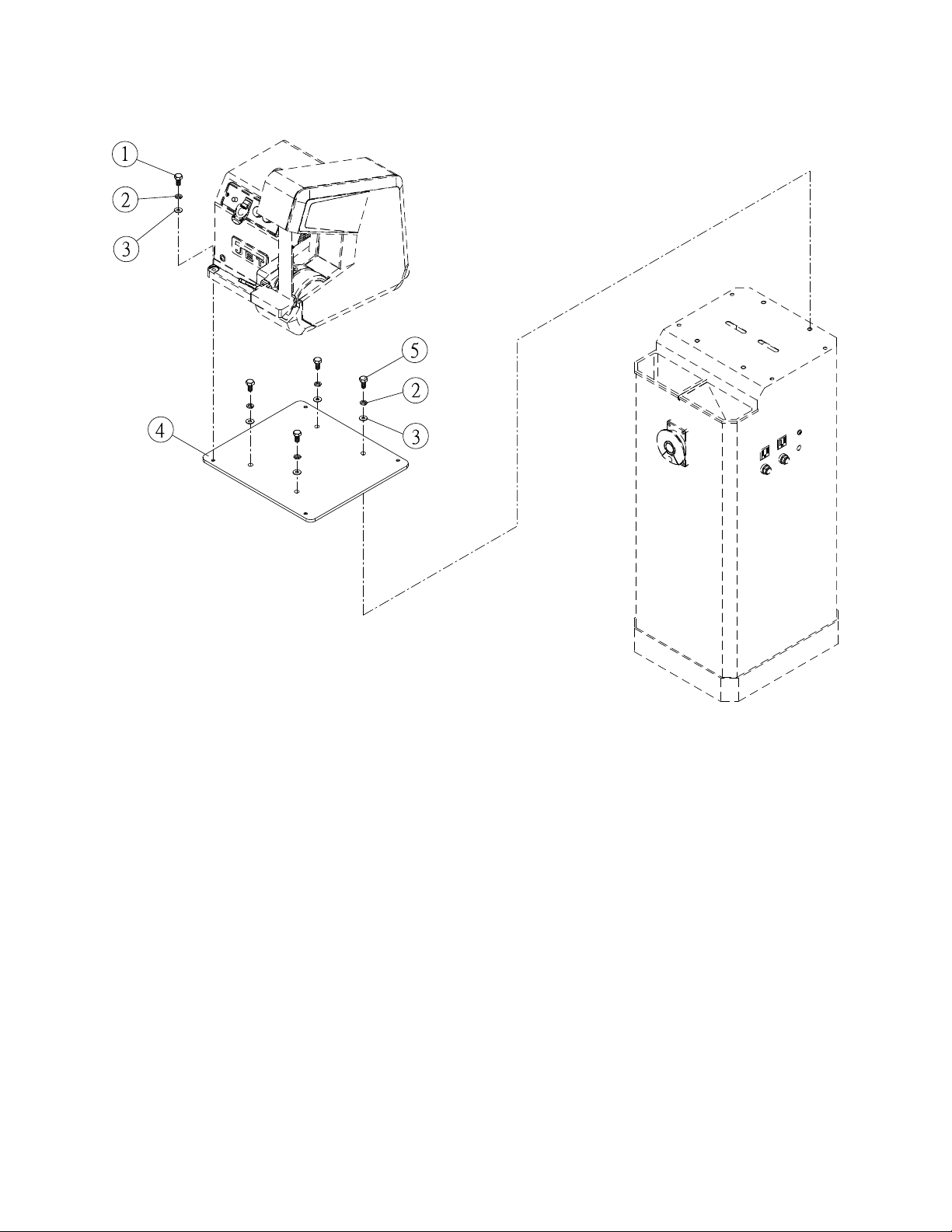
12.5.1 Adaptor Plate (OPTIONAL) – Exploded View – Model BGB-142/248
12.5.2 Adaptor Plate (OPTIONAL) – Parts List – Model BGB-142/248
Index No Part No Description Size Qty
.................. 414832 ...................... Adaptor Plate Kit, BGB-142/248 (#1 thru 5) ............ ........................................
1 ................ TS-149105 ................ Hex Cap Screw ........................................................ M10 x 1.5P x 35L ......... 4
2 ................ TS-2361101 .............. Lock Washer ............................................................ M10 .............................. 8
3 ................ TS-1550071 .............. Flat Washer ............................................................. 10 x 20 x 1.5T ............... 8
4 ................ BGB248-304 ............. Adaptor Plate ........................................................... ...................................... 1
5 ................ TS-1491021 .............. Hex Cap Screw ........................................................ M10 x 1.5P x 20L ......... 4
29

12.6.1 Adaptor Plate (OPTIONAL) – Exploded View – Model BGB-260-1/260-3
12.6.2 Adaptor Plate (OPTIONAL) – Parts List – Model BGB-260-1/260-3
Index No Part No Description Size Qty
.................. 414833 ...................... Adaptor Plate Kit, BGB-260-1/260-3 (#1 thru 5) ...... ........................................
1 ................ TS-149105 ................ Hex Cap Screw ........................................................ M10 x 1.5P x 35L ......... 4
2 ................ TS-2361101 .............. Lock Washer ............................................................ M10 .............................. 8
3 ................ TS-1550071 .............. Flat Washer ............................................................. 10 x 20 x 1.5T ............... 8
4 ................ BGB260-1-304 .......... Adaptor Plate ........................................................... ...................................... 1
5 ................ TS-1491021 .............. Hex Cap Screw ........................................................ M10 x 1.5P x 20L ......... 4
30

13.0 Electrical Connections
13.1 Wiring diagram – 115V (Models BGB-141/248/260-1)
31

13.2 Wiring diagram – 1PH, 230V (Models BGB-141/248/260-1)
32
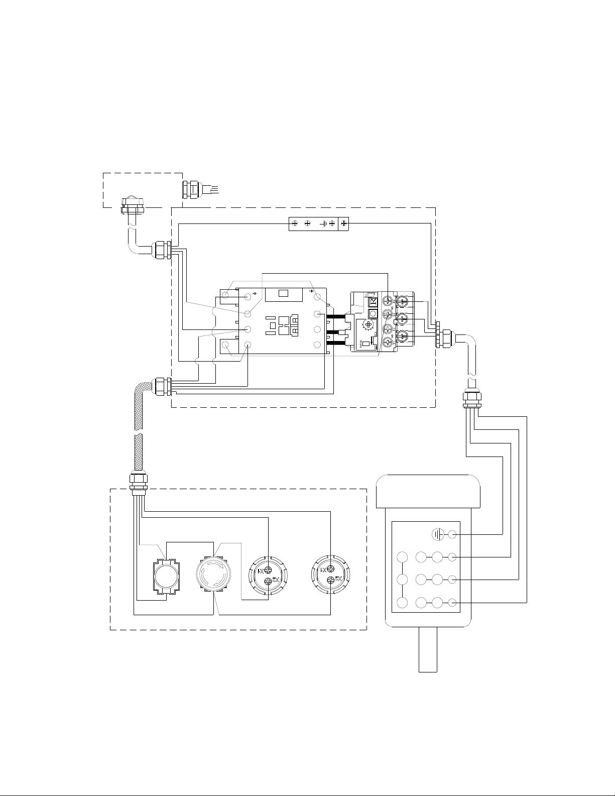
13.3 Wiring diagram – 3PH, 230V (Model BGB-260-3)
Terminal Box
PE
GN
GN
RD: Red
BK: Black
YE: Yellow
GY: Grey
Color Symbol:
GN: Green
RD
RD
Magnetic Switch
3Ph, 230V
A2
WH
A1
13
L3
5
L2
3
L1
1
14
T3
6
T2
4
T1
2
T
T
T
T
46
46
46
46
WH RD
1232
1232
1232
123
TT
TT
TT
TT
2
BK
BK
BK,1
BK
WH
WH,1
Motor, 3Ph, 230V
GN
BK,1
BK
WH,1
RD
56
RD
Control Panel
BK
WH
ON Switch
E-Stop
RD
Running Light
BK
33
Power Light
789
4
123
WH
BK

13.4 Wiring diagram – 3PH, 460V (Model BGB-260-3)
Terminal Box
PE
GN
GN
RD: Red
Color Symbol:
GN: Green
YE: Yellow
BK: Black
GY: Grey
Magnetic Switch
3Ph, 460V
RD
RD
A2
13
L3
5
WH
BK,1
A1
BK
BK
L2
3
L1
1
14
T3
6
T2
4
T1
2
WH
WH,1
RD
WH
2T T46T1232T T46T1232T T46T1232T T46T123
BK
Motor, 3Ph, 460V
GN
BK,1
BK
WH,1
RD
56
RD
Control Panel
BK
WH
ON Switch
E-Stop
RD
WH
BK
4
789
123
BK
34
Power Light
Running Light

14.0 Warranty and service
JET warrants every product it sells against manufacturers’ defects. If one of our tools needs service or repair, please
contact Technical Service by calling 1-800-274-6846, 8AM to 5PM CST, Monday through Friday.
Warranty Period
The general warranty lasts for the time period specified in the literature included with your product or on the official
JET branded website.
• JET products carry a limited warranty which varies in duration based upon the product. (See chart below)
• Accessories carry a limited warranty of one year from the date of receipt.
• Consumable items are defined as expendable parts or accessories expected to become inoperable within a
reasonable amount of use and are covered by a 90 day limited warranty against manufacturer’s defects.
Who is Covered
This warranty covers only the initial purchaser of the product from the date of delivery.
What is Covered
This warranty covers any defects in workmanship or materials subject to the limitations stated below. This warranty
does not cover failures due directly or indirectly to misuse, abuse, negligence or accidents, normal wear-and-tear,
improper repair, alterations or lack of maintenance. JET woodworking machinery is designed to be used with Wood.
Use of these machines in the processing of metal, plastics, or other materials outside recommended guidelines may
void the warranty. The exceptions are acrylics and other natural items that are made specifically for wood turning.
Warranty Limitations
Woodworking products with a Five Year Warranty that are used for commercial or industrial purposes default to a
Two Year Warranty. Please contact Technical Service at 1-800-274-6846 for further clarification.
How to Get Technical Support
Please contact Technical Service by calling 1-800-274-6846. Please note that you will be asked to provide proof
of initial purchase when calling. If a product requires further inspection, the Technical Service representative will
explain and assist with any additional action needed. JET has Authorized Service Centers located throughout the
United States. For the name of an Authorized Service Center in your area call 1-800-274-6846 or use the Service
Center Locator on the JET website.
More Information
JET is constantly adding new products. For complete, up-to-date product information, check with your local distributor
or visit the JET website.
How State Law Applies
This warranty gives you specific legal rights, subject to applicable state law.
Limitations on This Warranty
JET LIMITS ALL IMPLIED WARRANTIES TO THE PERIOD OF THE LIMITED WARRANTY FOR EACH PRODUCT.
EXCEPT AS STATED HEREIN, ANY IMPLIED WARRANTIES OF MERCHANTABILITY AND FITNESS FOR A
PARTICULAR PURPOSE ARE EXCLUDED. SOME STATES DO NOT ALLOW LIMITATIONS ON HOW LONG AN
IMPLIED WARRANTY LASTS, SO THE ABOVE LIMITATION MAY NOT APPLY TO YOU.
JET SHALL IN NO EVENT BE LIABLE FOR DEATH, INJURIES TO PERSONS OR PROPERTY, OR FOR
INCIDENTAL, CONTINGENT, SPECIAL, OR CONSEQUENTIAL DAMAGES ARISING FROM THE USE OF OUR
PRODUCTS. SOME STATES DO NOT ALLOW THE EXCLUSION OR LIMITATION OF INCIDENTAL OR
CONSEQUENTIAL DAMAGES, SO THE ABOVE LIMITATION OR EXCLUSION MAY NOT APPLY TO YOU.
JET sells through distributors only. The specifications listed in JET printed materials and on official JET website are
given as general information and are not binding. JET reserves the right to effect at any time, without prior notice,
those alterations to parts, fittings, and accessory equipment which they may deem necessary for any reason
whatsoever. JET
Product Listing with Warranty Period
90 Days – Parts; Consumable items
1 Year – Motors; Machine Accessories
2 Year – Metalworking Machinery; Electric Hoists, Electric Hoist Accessories; Woodworking Machinery used
for industrial or commercial purposes
5 Year – Woodworking Machinery
Limited Lifetime – JET Parallel clamps; VOLT Series Electric Hoists; Manual Hoists; Manual Hoist
Accessories; Shop Tools; Warehouse & Dock products; Hand Tools; Air Tools
NOTE: JET is a division of JPW Industries, Inc. References in this document to JET also apply to JPW Industries,
Inc., or any of its successors in interest to the JET brand.
®
branded products are not sold in Canada by JPW Industries, Inc.
35

427 New Sanford Road
LaVergne, Tennessee 37086
Phone: 800-274-6848
www.jettools.com
36
 Loading...