

Page 1

Operating Instructions and Parts Manual
2-Wh eel Belt G rinder 3” x 79”
Model BG-37 9
WALTER MEIER (Manuf acturing) Inc.
427 New Sanford Road
LaVergne, Tennessee 37086 Part No. M- 414610
Ph.: 800-274-6848 Revision A 09/2011
www.walt er meier.c om Copyright © 2011 Walt er Meier (M anufacturi ng) Inc.
Page 2

1.0 Warranty and Service
Walter Meier (Manufacturing) Inc., warrants every product it sells. If one of our tools needs service or repair, one of
our Authorized Service Centers located throughout the United States can give you quick service. In most cases, any
of these Walter Meier Authorized Service Centers can authorize warranty repair, assist you in obtaining parts, or
®
perform routine maintenance and major repair on your JET
your area call 1-800-274-6848.
MORE INFORMATION
Walter Meier is consistently adding new products to the line. For complete, up-to-date product information, check with
your local Walter Meier distributor, or visit waltermeier.com.
WARRANTY
JET products carry a limited warranty which varies in duratio n based upon the product (MW = Metalworking, WW =
Woodworking).
WHAT IS COVERED?
This warranty covers any defects in workmanship or materials subject to the e xceptions stated below. Cutting tools,
abrasives and other consumables are excluded from warranty coverage.
WHO IS COVERED?
This warranty covers only the initial purchaser of the product.
WHAT IS THE PERIOD OF COVERAGE?
The general JET warranty lasts for the time period specified in the product literature of each product.
WHAT IS NOT COVERED?
Five Year Warranties do not cover woodworking (WW) products used for commercial, industrial or educational
purposes. Woodworking products with Five Year Warranties that are used for commercial, industrial or education
purposes revert to a One Year Warranty. This warranty does not cover defects due directly or indirectly to misuse,
abuse, negligence or accidents, normal wear-and-tear, improper repair or alterations, or lack of maintenance.
HOW TO GET SERVICE
The product or part must be returned for examination, postage prepaid, to a location designated by us. For the name
of the location nearest you, please call 1-800-274-6848.
You must provide proof of initial purchase date and an explanation of the complaint must accompany the
merchandise. If our inspection discloses a defect, we will repair or replace the product, or refund the purchase price,
at our option. We will return the repaired product or replacement at our expense unless it is determined by us that
there is no defect, or that the defect resulted from causes not within the scope of our warranty in which case we will,
at your direction, dispose of or return the product. In the event you choose to have the product returned, you will be
responsible for the shipping and handling costs of the return.
HOW STATE LAW APPLIES
This warranty gives you specific legal rights; you may also have other rights which vary from state to state.
LIMITATIONS ON THIS WARRANTY
WALTER MEIER (MANUFACTURING) INC., LIMITS ALL IMPLIED WARRANTIES TO THE PERIOD OF THE
LIMITED WARRANTY FOR EACH PRODUCT. EXCEPT AS STATED HEREIN, ANY IMPLIED WARRANTIES OR
MERCHANTABILITY AND FITNESS ARE EXCLUDED. SOME ST ATES DO NOT ALLOW LIMITATIONS ON HOW
LONG THE IMPLIED WARRANTY LASTS, SO THE ABOVE LIMITATION MAY NOT APPLY TO YOU.
WALTER MEIER SHALL IN NO EVENT BE LIABLE FOR DEATH, INJURIES TO PERSONS OR PROPERTY, OR
FOR INCIDENTAL, CONTINGENT, SPECIAL, OR CONSEQUENTIAL DAMAGES ARISING FROM THE USE OF
OUR PRODUCTS. SOME STATES DO NOT ALLOW THE EXCLUSION OR LIMITATION OF INCIDENTAL OR
CONSEQUENTIAL DAMAGES, SO THE ABOVE LIMITATION OR EXCLUSION MAY NOT APPLY TO YOU.
Walter Meier sells through distributors only. The specifications in Walter Meier catalogs are given as general
information and are not binding. Members of Walter Meier reserve the right to effect at any time, without prior notice,
those alterations to parts, fittings, and accessory equipment which they may deem necessary for any reason
®
whatsoever. JET
branded products are not sold in Canada by Walter Meier.
tools. For the name of an Authorized Service Center in
2
Page 3

2.0 Table of Contents
Section Page
1.0 Warranty and Service ...................................................................................................................2
2.0 Table of Contents .........................................................................................................................3
3.0 Safety Warnings...........................................................................................................................4
4.0 About this manual ........................................................................................................................5
5.0 Features ......................................................................................................................................6
6.0 Specifications...............................................................................................................................7
7.0 Set-Up and Assembly ...................................................................................................................8
7.1 Floor Diagram...........................................................................................................................8
7.2 Unpacking and cleanup .............................................................................................................8
7.3 Electrical Connectio ns ...............................................................................................................8
7.4 Voltage Conversion (3PH only) ..................................................................................................8
8.0 Adjustments .................................................................................................................................9
8.1 Belt tracking .............................................................................................................................9
8.2 Belt change ..............................................................................................................................9
8.3 Belt tension adjustment .............................................................................................................9
9.0 Operatio n ....................................................................................................................................9
9.1 Contact grinding .......................................................................................................................9
9.2 Surface grinding .......................................................................................................................9
10.0 Maintenance ..............................................................................................................................9
11.0 Troubleshooting ....................................................................................................................... 10
12.0 Replacement Parts ................................................................................................................... 10
12.1.1 BG-379 Belt Grinders – Exploded View................................................................................ 11
12.1.2 BG-379 Belt Grinders – Parts List........................................................................................ 12
13.1 Electrical Connectio ns – single phase only ................................................................................. 15
13.2 Electrical Connectio ns – 3 phase only........................................................................................ 16
3
Page 4

3.0 Safety Warnings
1. Read and understand the entire owner’s
manual before attempting assembly or
operation.
2. Read and understand the warnings posted
on the machi ne and in t his manual. Failure
to comply with all of these warnings may
cause serious injury.
3. Replace the warning labels if they become
obscured or removed.
4. This belt grinder is designed and intended
for use by pr operly tr ained a nd experie nced
personnel only. If you are not familiar with
the proper and safe operation of a belt
grinder, do not us e until proper t raining a nd
knowledge have bee n obtai ned.
5. Do not use this machine for other than its
intended use. If used for other purposes,
Walter M eier (Manufacturi ng), I nc., disclai ms
any real or i mplied warra nty a nd holds itself
harmless from any injury that may result
from that use.
6. Always wear approved safety glasses/face
shields while using this belt grinder.
(Everyday eyeglasses only have impact
resistant lenses; they are not safety
glasses.) Eye w ear shall be impact r esist ant,
protective safety glasses with side shields
which comply with ANSI Z87.1
specifications.
7. Before operating this belt grinder, remove
tie, rings, watches and other jewelr y, and r oll
sleeves up past the elbows. Do not wear
loose clothing, and confine long hair. Nonslip footwear or anti-skid floor strips are
recommended. Do not wear gloves or hold
the work with a rag when grinding.
8. Wear ear protectors ( plugs or muffs) during
extended periods of operat io n.
9. Some dust created by power sanding,
sawing, grinding, drilling and other
construction activities contains chemicals
known to cause cancer, birth defects or
other reproductiv e harm. Some e xamples of
these chemicals are:
• Lead from lead based paint.
• Crystalline silica from bricks, cement
and other masonry products.
• Arsenic and chromium from chemically
treat ed lumber.
Your risk of e xposure varies, de pending on
how often you do this type of work. To
reduce your exposure to these chemicals,
work in a well- ventilated area a nd work w ith
approved safety eq uipment, s uch as face or
dust masks that are specifically desig ned to
filter out microscopic particles.
10. Do not operate this machine while tired or
under the i nfluence of dr ugs, alc ohol or a ny
medication.
11. Make certain switch is in OFF position
before connecti ng machine to pow er supply.
12. Make cer t ain machine is properly grounded.
13. Make all machine adjustments or
maintenance with machine unplugged from
power source.
14. Remove adj usti ng keys and wrenches. Form
a habit of checking to see that keys and
adjusting wrenches are removed from the
machine before turning it on.
15. Keep safety guards in place at all times
when machine is in use. If removed for
maintenance purposes, use extreme c aution
and replace the guards immediately after
maintenance is complete.
16. The belt grinder should be secured to the
floor befor e using.
17. Check damaged part s. Befor e furt her us e of
the machine, a guard or other part that is
damaged should be carefully checked to
determine that it will operate properly and
perform its intended function. Check for
alignment of moving parts, binding of
moving parts, breakage of parts, mounting
and a ny other conditio ns that may aff ect its
operation. A guard or other part that is
damaged should be properly repaired or
replaced.
18. Provide for adequate space surrounding
work ar ea and non-glare, overhead lighti ng.
19. Keep the floor around the machine clean
and free of scrap mater ial, oil and grease.
20. Keep visitors a saf e distance fr om the wor k
area. Keep children a way.
21. Make your workshop child proof with
padlocks, master switches or by removing
starter keys.
22. Give your work undi vided attention. Look ing
around, carrying on a conversation and
“horse-play” are careless acts that can result
in serious injury.
23. Maintain a balanced sta nce at all times so
that you do not fall or lean against moving
4
Page 5

parts. Do not overreach or use excessive
force t o perfor m any machine operation.
24. Use the right tool at the correct speed and
feed rat e. Do not force a tool or at tac hme nt
to do a job for which it was not designed.
The right t ool will do the job bet t er and more
safely.
25. Use recommended accessories; improper
accessories may be hazardous.
26. Maintain t ools with care. Keep cutting t ools
sharp and clean for the best and safest
performance. Follow instructions for
lubricating and changing accessories.
27. Turn off machi ne and disconnect f r om pow er
before cleani ng. Use a br ush or co mpress ed
air to remove chips or debris — do not use
yo ur ha nd s .
28. Do not stand on the machine. Serious injury
could occur if the machine tips over.
29. Never leave the machine running
unattended. T ur n power off and do not leave
machine until it comes to a complete stop.
30. Remove loose items a nd unnecess ary wor k
pieces from the area before starting the
machine.
31. Do not grind magnesi um, as it may create a
fire hazard.
Familiarize your self with t he fo llowing safety
notices used in this manual.
This means that if precautions
are not heeded, it may result in minor injury
and/or possible machine damage.
This means that if precautions
are not heeded, it may result in serious or even
fatal injury.
4.0 About this manual
This manual is provided by Walter Meier (Manufacturing) Inc. covering the safe operation and
maintenance procedures for a JET Model BG-379 Belt Grinder. T his manual contains instructions on
installation, safety precautions, general operating procedures, maintenance instructions and parts
breakdown. Y our machine has been designed and constr ucted to provide years of t rouble-free oper ation
if used in accordance with instructions set forth in this document.
This manual is not intended to be an exhausti ve guide to belt grinder operational met hods, stock choice,
abrasive selectio n, etc. Additional knowledge ca n be obtained from experienced users or trade journals.
Whatever accepted methods ar e used, always make pers onal safety a priority.
If there are questions or comments, please co ntact your local supplier or Walt er Meier. Walter Meier can
also be reached at our web site: www.walt er meier.com.
Retain this manual for future reference. If the machine transfers ownership, the manual should
accompany it.
5
Page 6

5.0 Features
1. Spark trap
2. Eye shield
3. Front work support
4. Contact wheel
5. Top work s upport
6. Belt guard
7. Tracki ng adjustment k nob
8. Belt tension release lever
9. Industrial switch with overload pr otection
Figure 1
10. Angle lock handle (x2)
11. Dri ve wheel
12. Dust port
13. Side panel
14. Pedestal
15. Base
16. Hinged guard plate
17. Tension adjust me nt nuts
18. Swing-away saf et y guard
6
Page 7

6.0 Specifications
Model Number ........................................................................... BG-379-1........................................................ BG-379-3
Stock Number ................................................................................414610............................................................414615
Materials:
Pedestal and Base ......................................................................... steel................................................................ steel
Belt housing ................................................................................... steel................................................................ steel
Abrasive belt provided............................... zirconium, closed coat, 80G........................... zirconium, closed coat, 80G
Drive wheel ............................................................................ aluminum........................................................ aluminum
Contact wheel ...............................8” durometer (HRA60~65), serrated...............8” durometer (HRA60~65), serrated
Motor and Electricals:
Motor type .......... totally enclosed fan cooled, induction, capacitor start............. totally enclosed fan cooled, induction
Horsepower ........................................................................ 4 HP (3 kW).................................................... 4 HP (3 kW)
Phase ........................................................................................... single......................................................................3
Voltage .......................................................................................... 230V..............................230/460V (prewired 230V)
Listed FLA (full load amps) .......................................................... 34.7A...................................................... 15.6A/8.5A
Starting amps ............................................................................... 56.6A.................................................... 19.2A/11.6A
Running amps, no load ................................................................ 15.2A........................................................ 4.9A/2.2A
Start capacitor ............................................................... 400μF 250VAC...................................................................n/a
Run capacitor .................................................................. 50μF 450VAC...................................................................n/a
Cycle ............................................................................................. 60Hz............................................................... 60Hz
Motor speed ..........................................................................3360 RPM.......................................................3440 RPM
Power transfer ...................................................................... direct drive...................................................... direct drive
Power cable length.......................................................... 300 cm (10 ft)................................................... 183 cm (6 ft)
Power plug included ...........................................................................no....................................................................no
Controls ...............................................industrial push button, 24V, 30A.....................industrial push button, 24V, 30A
Recommended circuit and breaker/fuse
Noise emission:
Without load
With load
Dimensions and Capacities:
Abrasive belt size (LxW) ................................. 2000 x 75 mm (79” x 3”)................................. 2000 x 75 mm (79” x 3”)
Flat grinding surface......................................................... 530 mm (21”).................................................. 530 mm (21”)
Working height (variable) .............. 780 – 1150 mm (30-3/4” – 45-1/4”)................ 780 – 1150 mm (30-3/4” – 45-1/4”)
Belt speed
Contact wheel siz
Drive wheel size (Dia. x W) ................................. 225 x 75 mm (9” x 3”)..................................... 225 x 75 mm (9” x 3”)
Shipping carton (LxWxH) . 110 x 70 x 120cm (43-1/4”x27-1/2”x47-1/4”).. 110 x 70 x 120cm (43-1/4”x27-1/2”x47-1/4”)
Machine size (LxWxH) ..................103 x 63 x 105cm (40.5”x25”x41.2”)...............103 x 63 x 105cm (40.5”x25”x41.2”)
Base footprint (LxW) ............................................. 17” x 21” (43x53cm)....................................... 17” x 21” (43x53cm)
Dust Extraction:
Dust port outside diameter ................................................. 3” (76.2mm).................................................... 3” (76.2mm )
Dust collection minimum capacity required ...........450 cfm (12.74cmm).......................................450 cfm (12.74cmm)
Weights:
Net.................................................................................90 kg (198.4 lb)...............................................90 kg (198.4 lb)
Shipping ......................................................................130 kg (286.6 lb).............................................130 kg (286.6 lb)
1
subject to local and national electrical codes.
2
no load with dust collection. 3 grinding flat bar 50x15mm with dust collection.
The specifications in this manual were current at time of publication, but because of our policy of continuous
improvement, Walter Meier reserves the right to change specifications at any time and without prior notice, without
incurring obligations.
1
........................................ 50A.......................................................... 30A/15A
2
...................................85 db at 93mm (3.66”) distance......................85 db at 93mm (3.66”) distance
3
........................................88 db at 93mm (3.66”) distance......................88 db at 93mm (3.66”) distance
.................................................................40 m/s (131.2 fps)...........................................40 m/s (131.2 fps)
e (Dia. x W) ............................. 200 x 75 mm (8” x 3”)..................................... 200 x 75 mm (8” x 3”)
7
Page 8

7.0 Set-Up and Assembly
7.1 F l oor Diagram
Figure 2
7.2 Un packing and cleanu p
Inspect contents of shipping container for
shipping damage. Report any damage to your
distributor.
Remove all co nte nts f rom carton, a nd co mpare
to the contents list in this manual. Report any
part shortages to your distributor.
Do not discard carton or packing material until
belt grinder is assembled and running
satisfactorily.
Exposed metal areas may have a rust protect ant
applied. Remove this with a soft rag and WD40® or kerosene. (Do not use gasoline, paint
thinner, acetone, etc., as these will damage
painted surfaces.)
Contents of shipp ing container
1 Belt Grinder
1 Instructions and Parts M anual (not show n)
1 Warranty Card (not shown)
7.3 Electrical Connect ions
operator. During hard-wiring of the machine,
make sure t he fuses have bee n remo ved or t he
breakers have been tripped in the circuit to
which the machine will be connected. Place a
warning placard on the fuse holder or circuit
breaker to prevent it being turned on while the
machine is being wired.
Ground i ng Inst r uct ions
This machine must be grounded. I n the event of
a malfunction or breakdow n, grounding provides
a path of least resistance f or electric current t o
reduce the risk of elect r ic shock.
Improper connection of the equipmentgrounding conductor can result in a risk of
electric shock. The conductor with insulation
having an outer surface that is green with or
without yellow stripes, is the equipmentgrounding conduc t or . I f r epair or r eplacement of
the electric cord or plug is necessary, do not
connect t he equipment-gr ounding conductor t o a
live terminal.
Check with a qualified electrician or service
personnel if the grounding instructions are not
completely understood, or if in doubt as to
whether the tool is properly gr ounded. Repair or
replace a damaged or worn cord immediately.
Make sure the voltage of your power supply
matches the specificat ions on the motor plate of
the belt grinder.
It is recommended that the single-phase belt
grinder be connected to a dedicated, minimum
50 amp circ uit wit h a 50 a mp circuit breaker or
time-delay fuse; the three phase belt grinder (at
230 volt oper at io n) be connected to a dedicated
minimum 30 amp circuit with a 30 amp circuit
breaker or t ime delay fuse; and t he three phase
belt grinder (at 460 volt operation) be connected
to a ded icated, m inimum 15 amp c ircuit w ith 15
amp circuit breaker or time delay fuse. Local
codes take precedence over recommendations.
Electrical connections must
be made by a qualified electrician in
compliance with all relevant codes. This
machine must be prop erly grounded t o help
prevent electrical shock and possible fatal
injury.
The belt grinder is equipped with a single p hase
230 volt only motor; or a 3-phase 230/460V
(prew ired 230V) motor . A plug is not included.
You may either install a UL/CSA listed plug
suitable for the specified voltage, or hard-wire
the machine directly to a ser vice panel.
If the machine is to be hard-wired to a panel,
make sure a disconnect is available for the
7.4 Voltage Conversion (3PH only)
To convert t he 3-p hase belt gri nder from 230 to
460 volt operation:
1. Sw itch t he incom ing power leads accor ding
to the diagram i nside the motor junction box.
Similar diagra ms are fo und in Sectio n 13 of
this manual. (In case of discrepancy, the
diagrams i n t he motor juncti on box w ill take
precedence.)
2. Make sure connections to transformer are
suitable for t he new voltage.
3. If a plug is being used, install a UL/CSA
listed plug suitable for 460 volt operat ion.
8
Page 9

Extension Cords
6
The use of exte nsion cords is d iscouraged; try t o
position machines within reach of the power
source. If an extension cord becomes
necessary, make s ure the cord rating is suitable
for the amperage listed on the machi ne’s motor
plate. An undersized cord will cause a drop in
line voltage resulting in loss of power and
overheating.
Use Table 1 as a general guide in choos ing the
correct size cord. If in doubt, use the next
heavier gauge. T he smaller the ga uge number,
the heavier the cord.
Recommended Gauges (AWG) of Extension
Cords
Extension C or d Length *
25
50
75
100
150
feet
feet
feet
Amps
< 5 1
5 to 8 16 16 14 12 10 NR
8 to 12 14 14 12 10 NR NR
12 to 15 12 12 10 10 NR NR
15 to 20 10 10 10 NR NR NR
21 to 30 10 NR NR NR NR NR
*based on limiting the line voltage drop to 5V at 150%
of the rated amperes.
NR: Not Recommended.
16 16 14 12 12
Table 1
feet
feet
200
feet
2. Allow belt t o complet ely stop, then remo ve
spark tr ap (1).
3. Open side cover, and slacken belt by
pushing te nsion release lever (8) dow nward
(counterclockwise).
4. Install new belt accor ding to direction arrow s
printed on belt.
5. Move tension release lever (8) upward
(clockwise) to tighten belt.
6. Close side cover and reinstall spark t r ap ( 1).
8.3 Belt tension adjustment
Belt tension has been adjusted by the
manufacturer. If future adjustment is needed,
distance between the wheels can be changed
using the two hex nuts (17).
9.0 Operation
9.1 Contact grinding
The operator faces the contact wheel (4) and
holds the work piece with both hands. Note:
Keep hands away fr om contact area, which wil l
grow warm during operation.
The work piece is pushed against belt, and
rested upon front w or k support (3) if needed.
8.0 Adjustments
Numbers i n par entheses refer to Figure 1.
8.1 Bel t t racki ng
1. Open side panel (13) and spin drive wheel
(11) by hand to check preliminary tr acking.
2. Use tracking knob (7) to correct until belt
runs centered on wheels. Clockwise knob
rotation shifts belt toward the left;
counterclockwise toward the right, as viewed
from the contact wheel end.
3. Close side panel (13).
4. Connect machine to power and turn on to
check final tracking. Adjust as needed with
knob.
Do not operate machine with
side panel open.
8.2 Belt change
1. Disconnect machi ne from power .
9.2 Surface grinding
The operator faces the open belt guard (6)
during surfac e grinding. The work piece is held
with both hands and pushed hard against the
top wor k support (5).
10.0 Maintenance
Before doing maintenance
on the machine, disconnect it from the
electrical supply by pulling out the plug or
switching off the main switch! Failure to
comply may cause serious injur y.
Ball bearings ha ve been packed with grease a nd
sealed, and require no furt her lubricatio n.
Frequent cleaning is mandatory to ensure best
operation and exte nded life of t he belt grinder.
If graphite layer becomes damaged, replace it.
Use a brush to re move swarf from the wheels
and inter ior .
9
Page 10

Check belt periodically for cuts, frays, or worn
areas. Replace belt when these symptoms are
found.
Empty spark tr ap frequently.
If power cord is worn, cut, or damaged in any
way, have it replaced immediately.
11.0 Trouble shooting
Trouble Probable Cause Remedy
No incoming power. Check all connections.
Fuse blown, or circuit breaker tripped. Replace fuse, or reset circuit breaker.
Grinder will not start.
Poor belt tracking.
Cord damaged. Replace cord.
Starting capacitor malfunction (single
phase model).
Improper belt splice. Check belt for irregular seam or shape.
Excessive or insufficient belt tension. Set tension so belt is just taut.
Worn contact surfaces.
Misaligned wheels.
Replace starting capacitor.
Check durometer on contact wheel.
Replace worn wheel.
Check alignment of drive and contact
wheel. Adjust using tracking knob.
Check for slight crown (approx. 1/16”).
Lack of crown on drive wheel.
Slack belt. Insufficient belt tension. Set tension so belt is just taut.
Excessive belt tension. Set tension so belt is just taut.
Premature wear of
contact wheel.
Short belt life.
Grinding on one area of belt.
Excess deposits on belt; debris in
machine.
Excessive grinding pressure.
Grinding on one area of belt.
Replace drive wheel if crown is not
present.
Use entire belt work surface whenever
possible.
Clean or replace belt. Periodically clean
interior of grinder.
Allow belt to do the cutting. Excessive
pressure dulls belt and removes its grit.
Use entire belt work surface whenever
possible.
Table 2
12.0 Replacement Parts
Replacement part s ar e listed on t he fol low i ng pages. To order part s or r eac h our service department, call
1-800-274-6848, Monday through Friday (see our website for business hours, www.waltermeier.com).
Having the Model Numb er and Serial Number of your machine availab le whe n you call wi ll allow us to
serve you quickly and accurately.
10
Page 11

12.1.1 BG-379 Belt Grinders – Expl oded V i ew
11
Page 12

12.1.2 BG-379 Belt Grinders – Part s List
Index No. Part No. Description Size Qty
1 .............. S-75B-000 ...............Stand ................................................................................................. 1
2 .............. TS-2342121 ............Nylon Lock Hex Nut ....................................M12 ................................. 1
3 .............. TS-2360121 ............Flat Washer................................................12mm .............................. 3
4 .............. S-75B-006 ...............Inside Tube ........................................................................................ 1
5 .............. S-75B-004 ...............Stand ................................................................................................. 1
6 .............. TS-1540071 ............Hex Nut......................................................M10 ................................. 4
7 .............. TS-1550071 ............Flat Washer................................................10mm .............................. 4
8 .............. BG379-08................Internal Serrated Washer ............................10mm .............................. 4
9 .............. BG379-09................Socket Head Flat Screw ..............................M10x20 ............................ 4
10 ............ TS-1502021 ............Socket Head Cap Screw .............................M5x10.............................. 2
11 ............ BG379-11................External Serrated Washer ...........................12mm .............................. 2
12 ............ TS-1517041 ............Socket Head Flat Screw ..............................M12x50 ............................ 2
13 ............ S-75-1003 ...............Body .................................................................................................. 1
14 ............ S-75-14/1 ................Motor (for 1PH)...........................................4 HP 1PH 230V ................. 1
................ S-7 5 -1 4 /3 ................Mo to r (fo r 3PH)...........................................4HP 3PH 230/460V .......... 1
14-1 ......... BG379-14-1.............Retaining Ring ............................................25mm .............................. 3
14-2 ......... S-75-14-2 ................Motor Fan Cover................................................................................. 1
14-3 ......... TS-1501031 ............Socket Head Cap Screw .............................M4x10.............................. 3
14-4 ......... S-75-14-4 ................Motor Fan .......................................................................................... 1
14-5 ......... TS-1490041 ............Hex Cap Screw ..........................................M8x25.............................. 3
14-6 ......... TS-1550061 ............Flat Washer ................................................8mm ................................ 3
14-7 ......... TS-2361081 ............Lock Washer ..............................................8mm ................................ 3
14-8 ......... S-75-14-8 ................Housin g Cover.................................................................................... 1
14-9 ......... BB-6206 ..................Ball Bearing................................................6206 ................................ 2
14-10 ....... S-75-14-10/1 ...........Stator (for 1PH) .................................................................................. 1
................ S-75-14-10/3 ...........Stator (for 3PH) .................................................................................. 1
14-1 1 ....... S-75 -14-11 ..............Motor can iste r .................................................................................... 1
14-1 2 ....... S-75 -14-12 ..............Upper Junction Bo x ............................................................................ 1
14-1 3 ....... S-75 -14-13 ..............Lower Ju nc tion Box ............................................................................ 1
14-1 4 ....... TS- 2284082 ............Phillips Pan Head Machine Screw................M4x 8 ............................... 4
14-15 ....... S-75-14-15/1 ...........Rotor (for 1PH) ................................................................................... 1
................ S-75-14-15/3 ...........Rotor (for 3PH) ................................................................................... 1
14-1 6 ....... S-75 -14-16 ..............Wash er .............................................................................................. 1
14-1 7 ....... S-75 -14-17 ..............Cove r .................................................................................. ............... 1
14-1 8 ....... BG379-14-18 ...........Hex Bolt (fully threaded) ..............................M8x20.............................. 3
14-19 ....... S-75-14-19 ..............Centrifugal Switch (for 1PH) ................................................................ 1
14-2 0 ....... S-75 -14-20 ..............Start Capacitor (for 1PH) .............................400μF, 250VAC ................ 1
14-2 1 ....... S-75 -14-21 ..............Run Capacitor (f or 1PH) ..............................50μF, 450VA C .................. 1
15 ............ S-75-1022 ...............Thin Plain Washer .............................................................................. 1
16 ............ S-75-1023 ...............Belt Tension Release Base ................................................................. 1
17 ............ TS-1504031 ............Socket Head Cap Screw .............................M8x16.............................. 1
18 ............ S-75-1024 ...............Belt Tension Release Lever................................................................. 1
19 ............ BG379-19................Sleeve .......................................................M10x50 ............................ 1
20 ............ S-75-1019 ...............Shaft .................................................................................................. 1
21 ............ S-75-1001 ...............Belt Guard.......................................................................................... 1
22 ............ S-75-22 ...................Locking Handle...........................................10x63mm ......................... 1
23 ............ TS-1550071 ............Flat Washer................................................10mm .............................. 1
24 ............ S-75-24 ...................Graphite Layer............................................520x75mm ....................... 1
25 ............ TS-1540061 ............Hex Nut......................................................M8 ................................... 2
26 ............ BG379-26................Socket Head Flat Screw ..............................M10x16 ............................ 1
27 ............ TS-1550071 ............Flat Washer................................................10mm .............................. 1
28 ............ S-75-1030 ...............Top Work Support............................................................................... 1
29 ............ S-75-1033 ...............Top Work Support Plate ...................................................................... 1
30 ............ BG379-30................Lock Handle ...............................................M8x63.............................. 1
31 ............ TS-1550061 ............Flat Washer................................................8mm ................................ 1
32 ............ S-75-1032 ...............Eye Protection Base ........................................................................... 1
12
Page 13

Index No. Part No. Description Size Qty
33 ............ TS-1532042 ............Phillips Pan Head Machi ne Screw................M4x12.............................. 2
34 ............ BG379-34................Socket Head Cap Screw .............................M5x50.............................. 1
35 ............ 5712561 ..................Phillips Pan Head Machine Screw ................M5x8 ............................... 2
36 ............ S-75-1031 ...............Eye Protection Hinge .......................................................................... 1
37 ............ S-75-1029 ...............Eye Protection Cover .......................................................................... 1
38 ............ TS-1540021 ............Hex Nut......................................................M4 ................................... 2
39 ............ S-75-1034 ...............Block with Thread ............................................................................... 1
40 ............ S-75-1011 ...............Contact Wheel .................................................................................... 1
41 ............ BG379-41................Socket Head Flat Screw ..............................M10x16 ............................ 2
42 ............ TS-1550071 ............Flat Washer................................................10mm .............................. 2
43 ............ S-75-1013 ...............Work Support ..................................................................................... 1
44 ............ TS-1513031 ............Socket Head Flat Screw ..............................M5x16.............................. 1
45 ............ BG379-45................Stop Ring ...................................................42mm .............................. 2
46 ............ BB-6004ZZ ..............Ball Bearing................................................6004ZZ ............................ 2
47 ............ S-75-1012 ...............Shaft .................................................................................................. 1
48 ............ S-75-1014 ...............Spa cer ............................................................................................... 2
49 ............ S-75-1002 ...............Motor Support .................................................................................... 1
50 ............ TS-1541041 ............Nylon Lock Hex Nut ....................................M10 ................................. 1
51 ............ BG379-51................Butterfly Spring ...........................................10mm .............................. 1
52 ............ S-75-1025 ...............Screw Bar .......................................................................................... 1
53 ............ TS-1550061 ............Flat Washer................................................8mm ................................ 1
54 ............ S-75-1021 ...............Base .................................................................................................. 1
55 ............ BG379-55................Socket Head Countersunk Screw ................M6x25.............................. 2
56 ............ S-75-1017 ...............Shaft .................................................................................................. 1
57 ............ SBR30M-62.............Spring Pin ..................................................5x20mm ........................... 1
58 ............ S-75-1020 ...............Eccentric wheel .................................................................................. 1
59 ............ TS-1550061 ............Flat Washer................................................8mm ................................ 4
60 ............ TS-2361081 ............Lock Washer ..............................................8mm ................................ 4
61 ............ BG379-61................Hex Bolt, fully threaded ...............................M8x22.............................. 4
62 ............ S-75-1015 ...............Sprin g ................................................................................................ 2
63 ............ BG379-63................Elasticity pin ...............................................6x40mm ........................... 2
64 ............ S-75-1017 ...............Pin Shaft ............................................................................................ 1
65 ............ BG379-65................Retaining Ring ............................................10mm .............................. 3
66 ............ S-75-1018 ...............Draw Bar ............................................................................................ 1
67 ............ BG379-67................Butterfly Spring ...........................................12mm ............................ 12
68 ............ S-75-1016 ...............Support .............................................................................................. 1
69 ............ TS-2342121 ............Nylon Lock Hex Nut ....................................M12 ................................. 2
70 ............ TS-2245081 ............Socket Head Flat Screw ..............................M5x8 ............................... 1
71 ............ PRS76-044..............Catch ................................................................................................. 1
72 ............ BG379-72................Thin Hex Nut ..............................................M10 ................................. 1
73 ............ S-75-73 ...................Wing Handle ..............................................M10x25 ............................ 1
74 ............ TS-1550071 ............Flat Washer................................................10mm .............................. 1
75 ............ S-75-1035 ...............Side Panel ......................................................................................... 1
76 ............ BG379-76................Hex Bolt, fully threaded ...............................M10x30 ............................ 1
77 ............ S-75-1009 ...............Wash er .............................................................................................. 1
78 ............ S-75-1008 ...............Drive Wheel ....................................................................................... 1
79 ............ S-75-1036 ...............Spark Trap ......................................................................................... 1
80 ............ BG379-80................Hex Bolt, fully threaded ...............................M8x15.............................. 1
81 ............ TS-1550061 ............Flat Washer................................................8mm ................................ 1
82 ............ S-75-1037 ...............Knob .................................................................................................. 1
83 ............ S-75-83 ...................Adjustable Han dle.......................................M12x 32 ............................ 1
84 ............ BG379-84................Hex Screw .................................................M12x140 .......................... 1
85-1 ......... TS-1532052 ............Phillips Pan Head Machine Screw................M4x16.............................. 4
85-2 ......... TS-1550021 ............Flat Washer ................................................4mm ................................ 4
85-3 ......... S-75-85-3 ................Bracket .............................................................................................. 1
85-4 ......... TS-1533042 ............Phillips Pan Head Machine Screw................M5x12.............................. 2
85-5 ......... TS-1550031 ............Flat Washer ................................................5mm ................................ 2
85-6 ......... S-75-85-6 ................Start Switch (for 1PH) ......................................................................... 1
13
Page 14

Index No. Part No. Description Size Qty
85-7 ......... S-75-85-7 ................Stop Switch (for 1PH).......................................................................... 1
85-8 ......... S-75-85-8 ................Emergency Switch (for 1PH)........................SB ................................... 1
85-9 ......... TS-2284302 ............Pan Head Machi ne Screw ( f or 1PH).............M4x30.............................. 4
85-1 0 ....... TS- 1550031 ............Flat Washer (for 1PH) .................................5mm ................................ 2
85-1 1 ....... S-75 -85-11 ..............Ele ctric Box Cov er .............................................................................. 1
85-1 2 ....... S-75 -85-12 ..............Seal ................................................................................................... 1
85-1 3 ....... S-75 -85-13 ..............Ele ctric Box ........................................................................................ 1
85-1 4 ....... S-75 -85-14 ..............Cabl e .........................................................4x 1.5 ............................... 2
85-1 5 ....... TS- 2284082 ............Phillips Pan Head Machine Screw................M4x 8 ............................... 2
85-1 6 ....... S-75 -85-16 ..............Groun din g Copper .............................................................................. 1
85-17 ....... S-75-85-17 ..............A.C. Contactor (for 1PH) .............................KM................................... 1
85-18 ....... S-75-85-18 ..............Thermal Relay (for 1PH) .............................FR ................................... 1
85-1 9 ....... S-75 -85-19 ..............Tran sform er (for 1PH ) ......................................................................... 1
85-2 0 ....... 5712561 ..................Phillips Pan Head Machi ne Screw................M5x8 ............................... 2
85-2 1 ....... S75 -85-21 ...............Bo ard ................................................................................................. 1
85-2 2 ....... S75-8 5-2 2 ...............Cov er Pl ate ............................................................................ ............ 1
85-2 3 ....... S75-8 5 -2 3 ...............Stra i n Relief ...............................................M20x1.5 ........................... 2
85-24 ....... S75-85-24 ...............Cable for A.C. Contactor .............................4x1.5 ............................... 1
85-25 ....... S75-85-25 ...............A.C. Contactor (for 3PH) .............................KM................................... 1
85-26 ....... S75-85-26 ...............Thermal Relay (for 3PH) .............................FR ................................... 1
85-27 ....... S75-85-27 ...............Cable for Thermal Relay .............................4x1.5 ............................... 1
85-28 ....... S75-85-28 ...............Transformer (for 3PH) .................................1.5/0.75............................ 1
86 ............ S-75-040 .................Safety Guard ...................................................................................... 1
87 ............ TS-1540021 ............Hex Nut......................................................M4 ................................... 3
88 ............ TS-1532042 ............Phillips Pan Head Machi ne Screw................M4x12.............................. 3
89 ............ TS-1532042 ............Phillips Pan Head Machi ne Screw................M4x12.............................. 3
90 ............ S-75-90 ...................Hinge ................................................................................................. 1
91 ............ S-75-91 ...................Hose Clamp ....................................................................................... 4
92 ............ TS-2285352 ............Phillips Pan Head Machi ne Screw................M5x35.............................. 4
93 ............ TS-1540031 ............Hex Nut......................................................M5 ................................... 4
................ JET L OGO- 1 ............Jet Logo Plate ( not shown) ..........................2-3/4” x 8” ........................ 1
................ STRIPE-1-3/4 ..........JET Stripe (not shown) ................................1-3/4” w..................... per ft.
................ BG379-WL ..............Warning Label (not shown) ..........................2-3/4” x 5” ........................ 1
14
Page 15
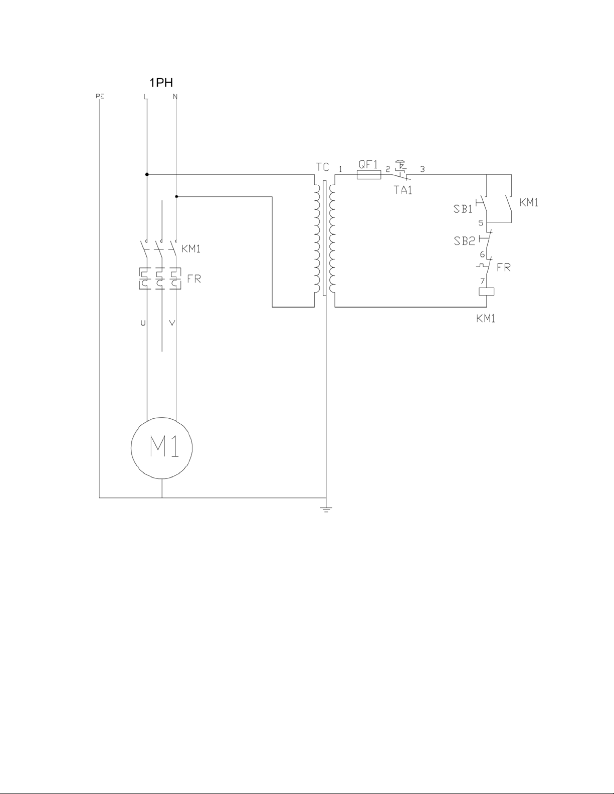
13.1 El ectrical Connections – single phase only
15
Page 16
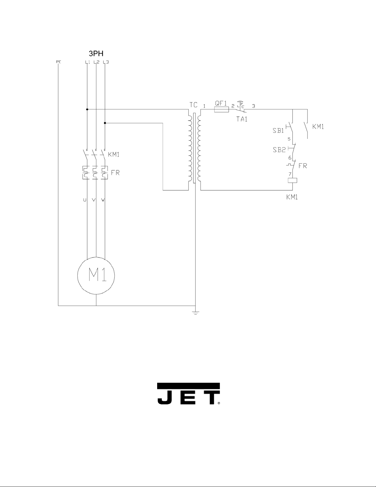
13.2 El ectrical Connections – 3 phase only
WALTER MEIER (Manuf acturing) Inc.
427 New Sanford Road
LaVergne, Tennessee 37086
Phone: 800-274-6848
www.waltermeier.com
16
 Loading...