

Page 1
BE-20 Bed Extension 20”
Assembly
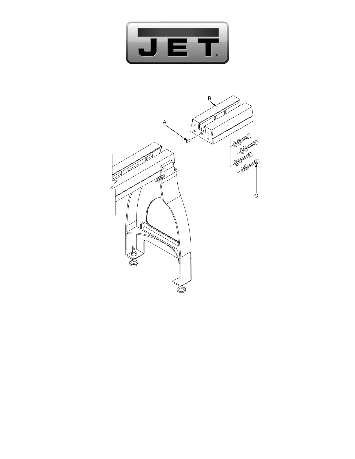
1. Tap straight end of t aper ed pin ( A ) into the c entering hole on the bed extension with a wooden mall et.
2. Lift into position and line up tapered pin that is mounted into the bed extension with the matched
centering hole in lathe bed.
3. Mount the bed extension (B ) to your JET Wood Lat he with four 3/ 8”-16x 1-3/ 4” hex socket cap screws
(C), four 3/8” loc k washers and four 3/8” flat washers. Snug the screws but do not ti ghten.
4. Move tailstock over the joint, and align the clamping nut in the center where the two beds meet.
Tighten tailstock clamping lever, and tighten the four hex socket cap screws that connect the beds.
5. The stud that is loc ated at the tailstock end of the lathe bed will need to be m oved t o the f ar end of
the extension bed.
JET
427 New Sanford Road
LaVergne, Tennessee 37086 Part No. M-708346
Ph.: 800-274-6848 Revision A1 06/2014
www.jettools.com Copyright © 2014 JET, a Div ision of JPW Industries, Inc.
Page 2
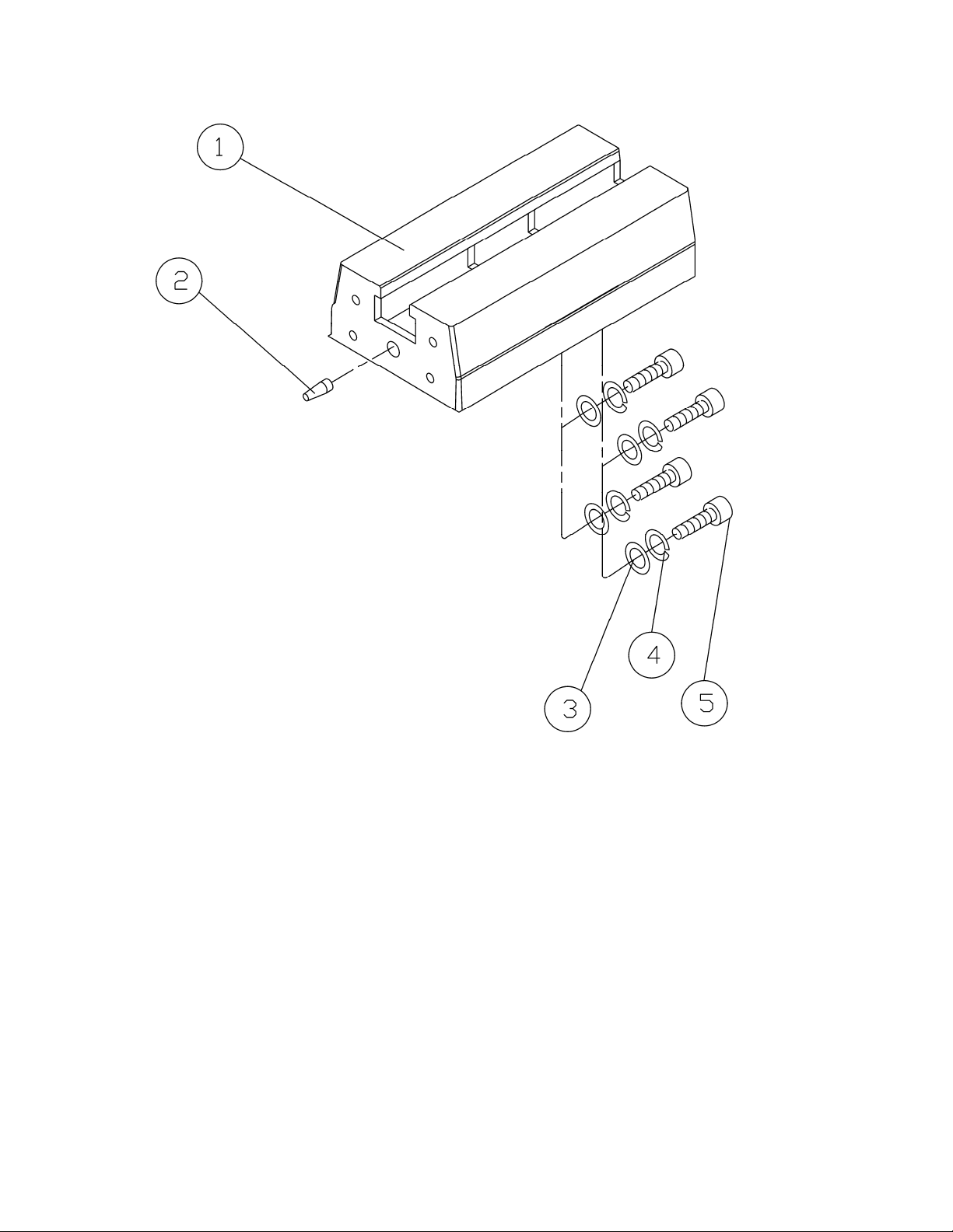
20” Bed Extension Breakdown
20” Bed Extension Parts List
Index Part
No. No. Description Size Qty.
............ 708346 .........................20” Bed Extension Assembly (includes #1-5) ...........................................
1 .......... JWL1642-401 ...............20” Bed Extension ................................. ............................................... 1
2 .......... JWL1642-302 ...............Tapered Pin ........................................... ............................................... 1
3 .......... TS-0680041 ..................Flat Washer ........................................... 3/8” ......................................... 4
4 .......... TS-0720091 ..................Lock Washe r ......................................... 3/8” ......................................... 4
5 .......... TS-0209081 ..................Hex Socket Ca p S cr e w .......................... 3/8”-16x1- 3 /4 ” ......................... 4
 Loading...