

Page 1

OWNER’S MANUAL
AFS-1500 Air Filtration
JET EQUIPMENT & TOOLS, INC. P.O. BOX 1349 253-351-6000
A WMH Company Auburn, WA 98071-1349 Fax 800-274-6840
www.jettools.com e-mail jet@jettools.com M-708614 6/2001
Page 2

2
This manual has been prepared for the owner and operators of a JET Air Filtration system. Its purpose,
aside from machine operation, is to promote safety through the use of accepted correct operating and
maintenance procedures. Completely read the safety and maintenance instructions before operating or
servicing the machine. To obtain maximum life and efficiency from your JET Air Filtration system, and to
aid in using the machine safely, read this manual thoroughly and follow instructions carefully.
Warranty & Service
The JET Group warrants every product it sells. If one of our tools needs service or repair, one of our
Authorized Repair Stations located throughout the United States can give you quick service.
In most cases, any one of these JET Group Repair Stations can authorize warranty repair, assist you in
obtaining parts, or perform routine maintenance and major repair on your JET, Performax or Powermatic
tools.
For the name of an Authorized Repair Station in your area, please call 1-800-274-6848.
More Information
Remember, the JET Group is consistently adding new products to the line. For complete, up-to-date
product information, check with your local JET Group distributor.
JET Group Warranty
The JET Group (including Performax and Powermatic brands) makes every effort to assure that its
products meet high quality and durability standards and warrants to the original retail consumer/purchaser
of our products that each product be free from defects in materials and workmanship as follow: 1 YEAR
LIMITED WARRANTY ON ALL PRODUCTS UNLESS SPECIFIED OTHERWISE. This Warranty does
not apply to defects due directly or indirectly to misuse, abuse, negligence or accidents, normal wear-andtear, repair or alterations outside our facilities, or to a lack of maintenance.
THE JET GROUP LIMITS ALL IMPLIED WARRANTIES TO THE PERIOD SPECIFIED ABOVE, FROM
THE DATE THE PRODUCT WAS PURCHASED AT RETAIL. EXCEPT AS STATED HEREIN, ANY
IMPLIED WARRANTIES OR MERCHANTIBILITY AND FITNESS ARE EXCLUDED. SOME STATES DO
NOT ALLOW LIMITATIONS ON HOW LONG THE IMPLIED WARRANTY LASTS, SO THE ABOVE
LIMITATION MAY NOT APPLY TO YOU. THE JET GROUP SHALL IN NO EVENT BE LIABLE FOR
DEATH, INJURIES TO PERSONS OR PROPERTY, OR FOR INCIDENTAL, CONTINGENT, SPECIAL,
OR CONSEQUENTIAL DAMAGES ARISING FROM THE USE OF OUR PRODUCTS. SOME STATES
DO NOT ALLOW THE EXLUSION OR LIMITATION OF INCIDENTAL OR CONSEQUENTIAL
DAMAGES, SO THE ABOVE LIMITATION OR EXCLUSION MAY NOT APPLY TO YOU.
To take advantage of this warranty, the product or part must be returned for examination, postage
prepaid, to an Authorized Repair Station designated by our office. Proof of purchase date and an
explanation of the complaint must accompany the merchandise. If our inspection discloses a defect, we
will either repair or replace the product, or refund the purchase price if we cannot readily and quickly
provide a repair or replacement, if you are willing to accept a refund. We will return repaired product or
replacement at JET’S expense, but if it is determined there is no defect, or that the defect resulted from
causes not within the scope of JET’S warranty, then the user must bear the cost of storing and returning
the product. This warranty gives you specific legal rights; you may also have other rights which vary from
statetostate.
The JET Group sells through distributors only. Members of the JET Group reserve the right to effect at
any time, without prior notice, those alterations to parts, fittings, and accessory equipment which they
may deem necessary for any reason whatsoever.
Page 3

3
WARNING
1. FOR YOUR OWN SAFETY, READ
INSTRUCTION MANUAL BEFORE
OPERATING THE TOOL. Learn the tool’s
application and limitations as well as the
specific hazards peculiar to it.
2. KEEP GUARDS IN PLACE and in working
order.
3. ALWAYS WEAR EYE PROTECTION.
4. GROUND ALL TOOLS. If tool is equipped
with three prong plug, it should be plugged
into a three-hole electrical receptacle. If an
adapter is used to accommodate a two
prong receptacle, the adapter lug must be
attached to a known ground. Never remove
the third prong.
5. KEEP WORK AREA CLEAN. Cluttered
areas and benches invite accidents.
6. DON’T USE IN DANGEROUS
ENVIRONMENT. Don’t use power tools in
damp or wet locations, or expose them to
rain. Keep work area well-lighted.
7. KEEP CHILDREN AND VISITORS AWAY.
All children and visitors should be kept a
safe distance from work area.
8. MAKE WORKSHOP CHILDPROOF. Use
padlocks, master switches, or remove
starter keys.
9. DON’T FORCE TOOL. It will do the job
better and be safer at the rate for which it
was designed.
10. USE RIGHT TOOL. Don’t force tool or
attachment to do a job for which it was not
designed.
11. WEAR PROPER APPAREL. No loose
clothing, gloves, neckties, rings, bracelets,
or other jewelry to get caught in moving
parts. Nonslip footwear is recommended.
Wear protective hair covering to contain long
hair.
12. ALWAYS USE SAFETY GLASSES. Wear
safety glasses (must comply with ANSI
Z87.1). Everyday eyeglasses only have
impact resistant lenses; they are not safety
glasses. Also use face or dust mask if
cutting operation is dusty.
13. SECURE WORK. Use clamps or a vise to
hold work when practical. It’s safer than
using your hands and frees both hands to
operate tool.
14. DON’T OVERREACH. Keep proper footing
and balance at all times.
15. MAINTAIN TOOLS IN TOP CONDITION.
Keep tools sharp and clean for best and
safest performance. Follow instructions for
lubricating and changing accessories.
16. DISCONNECT TOOLS before servicing
and when filters.
17. USE RECOMMENDED ACCESSORIES.
The use of accessories and attachments not
recommended by manufacturer may cause
hazards or risk of injury to persons.
18. AVOID ACCIDENTAL STARTING. Make
sure switch is in “OFF”position before
plugging in power cord.
19. NEVER STAND ON TOOL. Serious injury
could occur if the tool is tipped or if the fan
blade is accidentally contacted.
20. CHECK DAMAGED PARTS. Before further
use of the tool, a guard or other part that is
damaged should be carefully checked to
ensure that it will operate properly and
perform its intended function-check for
alignment of moving parts, binding of
moving parts, breakage of parts, mounting,
and any other conditions that may affect its
operation. A guard or other part that is
damaged should be properly repaired or
replaced.
21. NEVER LEAVE TOOL RUNNING
UNATTENDED. TURN POWER OFF.
Don’t leave tool until it comes to a complete
stop.
22. DRUGS, ALCOHOL, MEDICATION. Do not
operate tool while under the influence of
drugs, alcohol or any medication.
23. MAKE SURE TOOL IS DICONNECTED
FROM POWER SUPPLY while motoris
being mounted, connected or reconnected.
24. WARNING: Some dust created by power
sanding, sawing, grinding, drilling and other
construction activities contains chemicals
known to cause cancer, birth defects or
other reproductive harm. Some examples of
these chemicals are:
• Lead from lead based paint
• crystalline silica from bricks and cement
and other masonry products, and
• arsenic and chromium from chemicallytreated lumber.
25. Your risk from those exposures varies,
depending on how often you do this type of
work. To reduce your exposure to these
chemicals: work in a well ventilated area,
and work with approved safety equipment,
such as those dust masks that are
specifically designed to filter out microscopic
particles
Page 4

4
Electrical Requirements
In the event of a malfunction or breakdown, grounding provides a path of least resistance for electric
current to reduce the risk of electric shock. This tool is equipped with an electric cord having an
equipment-grounding conductor and a grounding plug. The plug must be plugged into a matching outlet
that is properly installed and grounded in accordance with all local codes and ordinances.
Do not modify the plug provided. If it will not fit the outlet, have the proper outlet installed by a qualified
electrician.
Improper connection of the equipment-grounding conductor can result in a risk of electric shock. The
conductor, with insulation having an outer surface that is green with or without yellow stripes, is the
equipment-grounding conductor. If repair or replacement of the electric cord or plug is necessary, do not
connect the equipment-grounding conductor to a live terminal.
Check with a qualified electrician or service personnel if the grounding instructions are not completely
understood, or if in doubt as to whether the tool is properly grounded.
Use only three wire extension cords that have three-prong grounding plugs and three-pole receptacles
that accept the tool’s plug.*
Repair or replace a damaged or worn cord immediately.
This tool is intended for use on a circuit that has an outlet that looks like the one illustrated in Figure A
below. The tool has a grounding plug that looks like the grounding plug as illustrated in Figure A below.
A temporary adapter, which locks like the adapter as illustrated in Figures B below, may be used to
connect this plug to a two-pole receptacle, as shown in Figure B if a properly grounded outlet is not
available.** The temporary adapter should only be used until a properly grounded outlet can be installed
by a qualified electrician. The green colored rigid ear or tab, extending from the adapter, must be
connected to a permanent ground such as a properly grounded outlet box.
* Canadian electrical codes require extension cords to be certified SJT type or better.
** Use of an adapter in Canada is not acceptable.
Page 5

5
Specifications AFS-1500
Stock Number................................................................................................................................ 708614
Outer Filter.................................................................................................................................5 Microns
Inner Filter................................................................................................................................... 1 Micron
Overall Dimensions (LxWxH/in).........................................................................................32-1/4 x 20 x 24
Sound Rating @ 3ft .......................................................................................................High Speed 70 dB
................................................................................................................................ Medium Speed 66 dB
...................................................................................................................................... Low Speed 58 dB
Air Flow................................................................................................................. High Speed 1300 CFM
...........................................................................................................................Medium Speed 900 CFM
.................................................................................................................................Low Speed 750 CFM
Motor................................................................................................................. 1/4 HP, 115V, 115V Only
Shipping Size (LxWxH/in) .......................................................................................................34 x22x18
Net Weight.......................................................................................................................................75 lbs.
ShippingWeight............................................................................................................................82.5 lbs.
Table of Contents Page
Warranty..................................................................................................................................................2
Warnings ....................................................................................................................... ..........................3
Electrical Requirements...........................................................................................................................4
Specifications..........................................................................................................................................5
Table Of Contents.................................................................................................................................... 5
For Your Own Safety...............................................................................................................................5
Contents of Shipping Carton....................................................................................................................6
Tools Required for Assembly ...................................................................................................................6
Assembly.................................................................................................................................................6
Controls and Features............................................................................................................................. 7
Changing Filters.......................................................................................................................................7
Breakdown ............................................................................................................................................18
Parts List............................................................................................................................................ 9-10
Wiring Diagram......................................................................................................................................10
FORYOUROWNSAFETY
1. Read and understand instruction manual before installing or operating air cleaner.
2. To reduce the risk of injury disconnect the air cleaner from the power source (unplug) before servicing
or changing filters.
3. If ceiling mounted, bottom of air cleaner must be at least 7 feet above the floor.
4. If ceiling mounted, mounts must be anchored to building structure which will support a minimum of at
least 150 pounds. Never mount to surfaces such as dry wall or false ceiling grids, etc.
5. To reduce the risk of electrical shock, do not expose air cleaner to water or rain.
6. Never duct a machine directly into the air cleaner.
7. To avoid a potentially dangerous situation, do not use this equipment to filter volatile fumes or smoke.
This air cleaner is designed and intended for the filtration of air borne wood dust only. It is neither
designed or intended for any other purpose whatsoever.
8. Failure to comply may result in serious injury and / or property damage.
The specifications in this manual are given as general information and are not binding. JET Equipment
& Tools reserves the right to effect, at any time and without prior notice, changes or alterations to parts,
fittings, and accessory equipment deemed necessary for any reason whatsoever.
Page 6

6
Contents of Shipping Carton
1. Air Filtration Unit
1. Remote Control
2. AAA Batteries
4. Eye Bolts & Hex Nuts
4. Pads
1. Velcro for Remote
1. Manual and Warranty Card
Tools Required for Assembly
10 mm Wrench
Cross Point Screwdriver
• The air filtration unit does not require much
assembly. You should take into
consideration how and where you will place
this unit.
• This unit will work best if it is located away
from corners, and heating/cooling vents.
• If using on sawhorses the air filtration unit
should be clamped in place.
• This unit is specifically designed to circulate
and filter non-metallic dust, which is
generated throughout the work area.
Assembly
CAUTION!
Mounts must be anchored to building
structure, which will support a minimum of
at least 150 pounds. Never mount to
surfaces such as dry wall or false ceiling
grids, etc.
1. Remove all packing from inside of the
unit by opening the side panel.
2. Make sure the hex nut (A, Fig. 1) is threaded
all the way up the eyebolt (B, Fig. 1).
3. Place a flat washer (C, Fig.1) on the eye
bolt. Screw the eye bolt into the cabinet and
tighten hex nut against the cabinet top. You
will need to hold the eyebolt so it does not
spin while tightening the lock nut.
4. Repeat steps for remaining three eyebolts.
Note: Make sure chain and ceiling hooks are
properly rated for hanging this unit. Hang unit
with a seven-foot clearance from the floor.
Page 7

7
Controls and Features
Remote Control:
Time button (A, Fig. 2) controls the three
different settings.
2H will light up on the back of the unit with one
press of the time button. The air filtration
system will operate for 2 hours then shut off.
4H will light up on the back of the unit by
pressing the time button twice. The air filtration
system will operate for 4 hours then shut off.
8H will light up on the back of the unit by
pressing the time button three times. The air
filtration system will operate for 8 hours then
shut off.
Speed but ton (B, Fig. 2) controls the three
different settings, Low, Medium and High. There
is also a manual button (C, Fig. 2) on the
backside of this unit which controls the speed.
On/Off button (D, Fig. 2) turns the unit on and
off. There is also a manual on/off button (E, Fig.
2) on the backside of the unit. Pressing this
button will turn the machine on Low.
The filters should be replaced depending on
the amount of usage and the environment of
your shop. Clogged filters will reduce the
amount of air circulation.
Order replacement filters using the below listed
stock numbers.
708727 Outer Filter (cardboard frame)
708729 Electrostatic Filter (metal frame
washable)
708726 Inner Filter
708728 Charcoal Filter
Overload reset switch (F, Fig. 2) will pop in the
case of overload. Wait 3-5 minutes and press
the reset switch back in to the normal position.
Changing the Filters
WARNING
To reduce the risk of injury disconnect the
air filtration unit from the power source
(unplug) before servicing or changing
filters. Failure to comply may cause
seriousinjury!
Outer Filter: removefromthesideofthe
cabinet (A, Fig. 3).
Inner Filter: you must remove the two bolts
that hold the cover in place. Remove the cover.
Remove the inner filter (B, Fig. 3) from the side
of the cabinet. Replace the cover and two bolts.
Accessory Filter: an additional charcoal
filter, or electrostatic filter can be added to this
empty slot (C, Fig.3). Replace the cover and
two bolts
Page 8

8
Parts Breakdown
Page 9

9
Parts List for the AFS-1500 Air Filtration
Index Part
No. No. Description Size Qty.
1..........330001............................. Fan Blade...................................................... .................................1
2..........330002............................. Fan Housing.................................................. .................................1
3..........330003............................. Air Guide Plate.............................................. .................................2
4..........330004............................. Flange........................................................... .................................1
5..........330005............................. Spacer........................................................... .................................4
6..........330006............................. Sleeve........................................................... .................................4
7..........330052............................. Box Cover..................................................... ................................. 1
............ LM000280........................JET Label (not shown)................................... .................................2
............ LM000350........................Warning Label (not shown) ............................ .................................1
8..........330071............................. Top Plate....................................................... .................................1
9..........BT000042........................ Rivet.............................................................. .................................8
10........330055............................. Side Plate...................................................... .................................1
11........AB330072........................ Frame............................................................ .................................1
12........330057............................. Fan Support (1)............................................. .................................1
13........330058............................. Fan Support (2)............................................. .................................1
14........330061............................. Side Cover.................................................... .................................1
15........AB330064........................ Frame............................................................ .................................1
16........330066............................. Motor............................................................. 1/4 HP, 115V............1
............ CA001500........................Capacitor (not shown).................................... .................................1
17........708727............................. Outer Filter (cardboard frame)........................ ................................. 1
............ 708729............................. Electrostatic Filter (metal frame: washable)... ...................................
18........708726............................. Bag Filter....................................................... .................................1
19........OO1023........................... Eye Bolt......................................................... .................................4
20........NH061000........................ Nut................................................................M6............................4
21........10042............................... Nut................................................................ ................................. 6
22........SR060600........................ Hex Socket Bolt............................................. M6x30...................... 4
23........WF061620 ....................... Washer..........................................................M6x16......................8
24........SR089400........................ Hex Socket Bolt............................................. M8x16...................... 1
25........SF069200 ........................ Pan Head Bolt W/Flange...............................M6x8......................22
26........ST049314 ........................ Tapping Screw .............................................. M4x12.................... 14
27........SJ089400......................... Pan Head Bolt...............................................M8x16...................... 6
28........WS080000....................... SpringWasher............................................... M8............................6
29........NF050800........................ Nut................................................................M5............................4
30........OO1029........................... Concave Handle............................................ .................................2
31........OO1033........................... Switch Wire W/Terminal................................. 18AWG.....................1
32........NH050800........................ Nut................................................................M5............................2
33........WE050000....................... Star Washer (External).................................. M5............................2
34........OO1022........................... Switch Plate................................................... .................................1
35........SP059300........................ Pan Head Bolt...............................................M5x12......................1
36........IC001015......................... Cord..............................................................18AWGx3C..............1
37........998623............................. Strain Relief................................................... .................................1
38........330075............................. 5A Thermal Switch ........................................ .................................1
39........ST049100 ........................ Tapping Screw .............................................. M4x6........................4
40........SN490200........................ Counter Sunk Bolt ......................................... 1/8”x1/4”...................3
41........330043............................. PC Board....................................................... .................................1
42........LM000453........................ Circuit Board Label........................................ .................................1
43........990638............................. Wiring Nut.....................................................P2.............................1
44........708711............................. Remote Control............................................. .................................1
45........LM000344........................ Remote Label................................................ .................................1
48........330030............................. Bolt................................................................ .................................2
52........330046............................. Pad ............................................................... .................................2
53........330074............................. Round Pad .................................................... .................................4
Page 10
1
Optional Replacement Filters:
............ 708727............................. Outer Filter (cardboard frame)........................ ...................................
............ 708729............................. Electrostatic Filter (metal frame: washable)... ...................................
............ 708726............................. Inner Filter..................................................... ...................................
............ 708728............................. Charcoal Filter............................................... ...................................
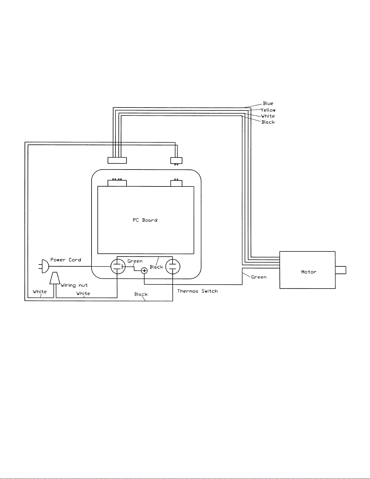
Wiring Diagram
0
 Loading...