

Page 1
Operating Instructions and Parts Manual
14ga. x 52-inch Hydraulic Shear
Model HS-1452
JET
427 New Sanford Road
LaVergne, Tennessee 37086 Part No. M-756205
Ph.: 800-274-6848 Revision B1 06/2014
www.jettools.com Copyright © 2014 JET
Page 2

1.0 Warranty and Service
90 Days – Parts; Consumable items; Light-Duty Air Tools
1 Year – Motors; Machine Accessories; Heavy-Duty Air Tools; Pro-Duty Air Tools
2 Year – Metalworking Machinery; Electric Hoists, Electric Hoist Accessories
5 Year – Woodworking Machinery
Limited Lifetime – JET Parallel clamps; VOLT Series Electric Hoists; Manual Hoists; Manual Hoist
JET® warrants every product it sells against manufacturers’ defects. If one of our tools needs service or repair, please
contact Technical Service by calling 1-800-274-6846, 8AM to 5PM CST, Monday through Friday.
Warranty Period
The general warranty lasts for the time period specified in the literature included with your product or on the official
JET branded website.
• JET products carry a limited warranty which varies in duration based upon the product. (See chart below)
• Accessories carry a limited warranty of one year from the date of receipt.
• Consumable items are defined as expendable parts or accessories expected to become inoperable within a
reasonable amount of use and are covered by a 90 day limited warranty against manufacturer’s defects.
Who is Covered
This warranty covers only the initial purchaser of the product from the date of delivery.
What is Covered
This warranty covers any defects in workmanship or materials subject to the limitations stated below. This warranty
does not cover failures due directly or indirectly to misuse, abuse, negligence or accidents, normal wear-and-tear,
improper repair, alterations or lack of main tena nc e.
Warranty Limitations
Woodworking products with a Five Year Warranty that are used for commercial or industrial purposes default to a Two
Year Warranty. Please contact Technical Service at 1-800-274-6846 for further clarification.
How to Get Technical Support
Please contact Technical Service by calling 1-800-274-6846. Please note that you will be asked to provide proof of
initial purchase when calling. If a product requires further inspection, the Technical Service representative will
explain and assist with any additional action needed. JET has Authorized Service Centers located throughout the
United States. For the name of an Authorized Service Center in your area call 1-800-274-6846 or use the Service
Center Locator on the JET website.
More Information
JET is constantly adding new products. For complete, up-to-date product information, check with your local distributor
or visit the JET website.
How State Law Applies
This warranty gives you specific legal rights, subject to applicable state law.
Limitations on This Warranty
JET LIMITS ALL IMPLIED WARRANTIES TO THE PERIOD OF THE LIMITED WARRANTY FOR EACH PRODUCT.
EXCEPT AS STATED HEREIN, ANY IMPLIED WARRANTIES OF MERCHANTABILITY AND FITNESS FOR A
PARTICULAR PURPOSE ARE EXCLUDED. SOME STATES DO NOT ALLOW LIMITATIONS ON HOW LONG AN
IMPLIED WARRANTY LASTS, SO THE ABOVE LIMITATION MAY NOT APPLY TO YOU.
JET SHALL IN NO EVENT BE LIABLE FOR DEATH, INJURIES TO PERSONS OR PROPERTY, OR FOR
INCIDENTAL, CONTINGENT, SPECIAL, OR CONSEQUENTIAL DAMAGES ARISING FROM THE USE OF OUR
PRODUCTS. SOME STATES DO NOT ALLOW THE EXCLUSION OR LIMITATION OF INCIDENTAL OR
CONSEQUENTIAL DAMAGES, SO THE ABOVE LIMITATION OR EXCLUSION MAY NOT APPLY TO YOU.
JET sells through distributors only. The specifications listed in JET printed materials and on official JET website are
given as general information and are not binding. JET reserves the right to effect at any time, without prior notice,
those alterations to parts, fittings, and accessory equipment which they may deem necessary for any reason
whatsoever. JET
Product Listing with Warranty Period
®
branded products are not sold in Canada by JPW Industries, Inc.
Accessories; Shop Tools; Warehouse & Dock products; Hand Tools
NOTE: JET is a division of JPW Industries, Inc. Refer enc es i n this document to JET also apply to JPW Industries,
Inc., or any of its successors in interest to the JET brand.
2
Page 3

2.0 Table of Contents
Section Page
1.0 Warranty and Service ............................................................................................................................. 2
2.0 Table of Contents ................................................................................................................................... 3
3.0 Safety Warnings ..................................................................................................................................... 4
4.0 About this manual .................................................................................................................................. 5
5.0 General Features and Terminology ....................................................................................................... 6
6.0 Specifications ......................................................................................................................................... 7
7.0 Set-Up and Assembly ............................................................................................................................ 8
7.1 Hole center dimensions ...................................................................................................................... 8
7.2 Unpacking ........................................................................................................................................... 8
7.3 Stop assemblies ................................................................................................................................. 8
7.4 Electrical connections ......................................................................................................................... 9
8.0 Adjustments ........................................................................................................................................... 9
8.1 Adjustment for the shearing edge gap ............................................................................................... 9
8.2 Adjustment for back gauge ............................................................................................................... 10
9.0 Maintenance ......................................................................................................................................... 10
10.0 Troubleshooting the HS-1452 ............................................................................................................ 10
11.0 Replacement Parts ............................................................................................................................. 10
11.1.1 HS-1452 Hydraulic Shear – Exploded View ............................................................................... 11
11.1.2 HS-1452 Rear Stop and Press Plate – Exploded View.............................................................. 12
11.1.3 HS-1452 Hydraulic Regulator Assembly – Exploded View ........................................................ 13
11.1.4 HS-1452 Control Box – Exploded View ..................................................................................... 14
11.1.5 HS-1452 Hydraulic Shear Assembly – Parts List ...................................................................... 15
12.1 Electrical Connections – single phase onl y (HS-1452) ...................................................................... 18
12.2 Electrical Connections – 3 phase only (HS-1452) ............................................................................. 20
13.0 Hydraulic diagram (HS-1452) ............................................................................................................ 22
3
Page 4

3.0 Safety Warnings
1. Read and understand the entire owner’s manual before attempting assembly or operation.
2. Read and understa nd the warnings pos ted on the m achine and i n this m anua l. F ailure t o com pl y with
all of these warnings m ay cause serious injury. Replace warnin g labels if they become obscur ed or
removed.
3. This pneumatic Hydraulic shear is designed and intended for use by properly trained and experienced
personnel only. If you ar e not familiar with the pr oper and safe oper ation of a shear, do n ot use until
proper training and knowledge have been obtained.
4. Do not use this mac hine f or other than its intended use . If used for other purposes, JET dis c laims any
real or implied warranty and holds itself harmless from any injury that may result from that use.
5. Always wear ANSI a pprove d saf ety gl asses /fac e shields while us ing t his sh ear. Ev eryday eyeglas ses
only have impact resistant lenses; they are not safety glasses.
6. Do not wear loose cloth ing, gloves, neck ties, rings, bracelets, or other jewelr y which may get caught
in moving parts. Wear protective hair co vering to contain long ha ir . No n-slip footwear or anti-skid floor
strips are recommended.
7. Some dust created by power sanding, sawing, grinding, drilling and other construction activities
contains chemicals known to caus e cancer , birt h defects or other r eprod uctive har m . Some ex amples
of these chemicals are:
• Lead from lead based paint.
• Crystalline silica from bricks, cement and other masonry products.
• Arsenic and chromium from chemically treated lumber.
Your risk of exposure varies, depending on how often you do this type of work. To reduce your
exposure to these chemicals, work in a well-ve nti lat ed ar ea a nd work w ith a ppro v ed s af et y equ ipment,
such as face or dust masks that are specifically designed to filter out microscopic particles.
8. Do not operate this machine while tired or under the influence of drugs, alcohol or any medication.
9. Do not exceed the rated capacity of this shear; use hand tools for small or narrow parts. Do not
attempt to shear hardened materials.
10. Sheet metal stock has sharp edges. To prevent cuts, use leather work gloves when handling.
11. Keep hands and fingers clear of the area in front and rear of the shear.
12. Do not place your hands between material being sheared and the shear table.
13. Keep safety guards in place at all times when the machine is in use. If removed for maintenance
purposes, use extreme caution and replace the guards immediately after maintenance is complete.
14. Check damaged parts. Before further use of the machine, a guard or other part that is damaged
should be carefully checked to determine that it will operate properly and perform its intended function.
Check for alignm ent of moving parts, binding of moving parts, break age of parts, mounting a nd any
other conditions that may affect its operation. A guard or other part that is damaged should be
properly repaired or replaced.
15. Provide for adequate space surrounding work area and non-glare, overhead lighting.
16. Keep the floor around the machine clean and free of scrap material, oil and grease.
17. Keep visitors a safe distance from the work area. Keep children away.
18. Make your workshop child proof with padlocks, master switches or by removing starter keys.
19. Give your work undivided attent ion. Looking around , carrying o n a conversati on and “hors e-play” are
careless acts that can result in serious injury.
20. Maintain a balanced stance at all tim es so that you do not f all or lean against m oving parts. Do not
overreach or use excessive force to perform any machine operation.
21. Use the right tool at th e cor rec t spee d and feed rate. Do n ot f orce a too l or at tach m ent to d o a j ob f or
which it was not designed. The right tool will do the job better and more safely.
22. Use recommended accessories; improper accessories may be hazardous.
4
Page 5

23. Maintain tools with care. Keep tools sharp and clean for the best and safest performance. Follow
instructions for lubricating and changing accessories.
24. Do not stand on the machine. Serious injury could occur if the machine tips over.
25. Unplug or lock out power to the machine when not in use.
Familiarize yourself with the following safety notices used in this manual.
This means that if precautions are not heeded, it may result in minor injury and/or
possible machine damage.
This means that if precautions are not heeded, it may result in serious or even fatal
injury.
4.0 About this manual
This manual is provided by JET covering the safe operation and maintenance procedures for a JET
Model HS-1452 Hydraulic Shear. This manual contains instructions on installation, safety precautions,
general operating procedures, maintenance instruct ions and parts breakdo wn. Your machine has been
designed and constructed to provide years of trouble-free operation if used in accordance with the
instructions as set forth in this document.
If there are questions or comments, please contact your local supplier or JET. JET can also be reached at
our web site: www.jettools.com.
Retain this manual for future reference. If the machine transfers ownership, the manual should
accompany it.
5
Page 6
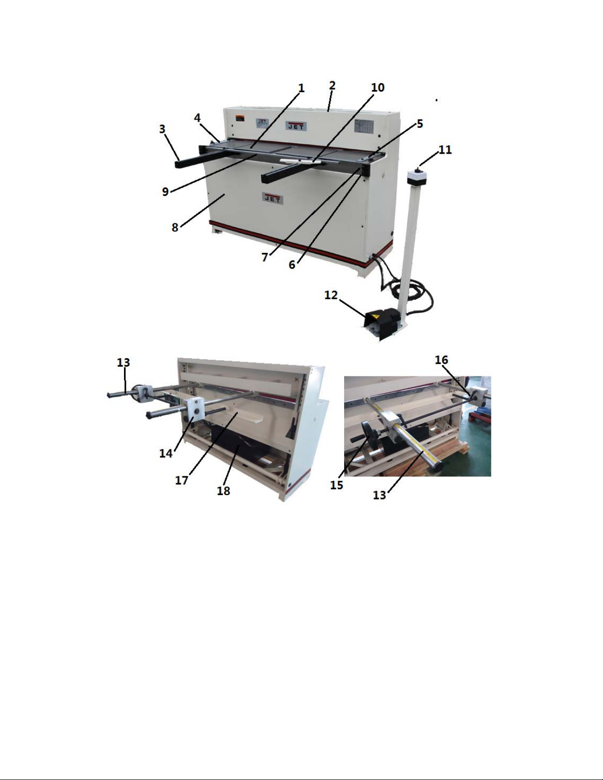
5.0 General Features a nd Terminology
1 Table
2 Cutter Bar
3 Front Arm Extension
4 Left Scale
5 Right Scale
6 Table Adjustment Screws
7 Table Adjustment Screws
8 Front Cover
9 Front Stop
Figure 1
10 Bevel Gauge
11 On/Off Switch
12 Foot Pedal
13 Scale
14 Adjusting Block
15 Adjusting Handwheel
16 Adjusting Block Knobs
17 Rear Stop
18 Hydraulic Regulator Assembly
6
Page 7

6.0 Specifications
Model Number....................................................................... HS-1452-1T ................................................... HS-1452-3T
Stock Number .............................................................................. 756205 ........................................................... 756206
Materials:
Frame .......................................................................................... steel ............................................................... steel
Table ............................................................................................ steel ............................................................... steel
............................................................. ground hardened steel ................................. ground hardened steel
Blades
Front Stop .................................................................................... steel ............................................................... steel
Rear Stop
Motor and Electricals:
Motor type........... totally enclosed fan cooled, induction, capacitor start ............ totally enclosed fan cool ed, in duct ion
Horsepower .................................................................... 3 HP (2.2 kW) ................................................ 3 HP (2.2 kW)
Phase .......................................................................................... single ..................................................................... 3
Voltage ........................................................ 115/230V (prewired 230V) ............................. 230/460V (prewired 230V)
Listed FLA (full load amps) ................................................ 26.5A/13.3A ....................................................... 8.3A/4.5A
Starting amps .................................................................... 45.6A/28.5A .................................................. 18.2A/10.6A
Running amps, no load ........................................................ 18.5A/9.6A ....................................................... 4.5A/2.1A
Start capacitor ............................................................. 300MF 175VAC .................................................................. n/a
Run capacitor ................................................................. 80µF 250VAC .................................................................. n/a
Cycle ............................................................................................ 60Hz .............................................................. 60Hz
Motor speed..........................................................................1700 RPM ...................................................... 1700 RPM
Power cable length ........................................................ 200 cm (6.6 ft) ................................................ 200 cm (6.6 ft)
Power plug included ......................................................................... no ................................................................... no
Foot pedal cable length ................................................. 8.2 ft. (250cm) ................................................... 8 ft. (200cm)
On/Off switch ............................................................................... rotary .............................................................. rotary
Control ..................................................................................Foot pedal ...................................................... Foot pedal
Noise emission ....................................................................... 40-60 dB ........................................................ 40-60 dB
Capacities:
Material thickness capacity – mild steel ............................. 14 gauge ....................................................... 14 gauge
Shearing length capacity
Back stop capacity ................................................ 25-1/2” (650mm) ........................................ 25-1/2” (650mm)
Front stop capacity ............................................... 23-1/2” (600mm) ........................................ 23-1/2” (600mm)
Dimensions :
Shipping carton (LxWxH) ............ 172 x 83 x 130cm (67.75”x32.7”x51.2”) ......... 172 x 83 x 130cm (67.75”x32.7”x51.2”)
Machine size (LxWxH) ....................... 158x196x108cm (62.2”x77”x42.5”) ................ 158x196x108cm (62.2”x77”x42.5”)
Hydraulic System:
Hydraulic hose length ............................................... 9.8 ft. (300cm) ............................................ 9.8 ft. (300cm)
Operating/maximum hydraulic pressure (psi) .......... 870psi (6Mpa) ........................................... 870psi (6Mpa)
Strokes per minute ....................................................... 20 with load ............................................... 20 with load
Recommended Hydraulic hose diameter ............................ Ф16mm ...................................................... Ф16mm
Weights:
Net ............................................................................... 595 kg (1335 lb) ............................................. 595 kg (1335 lb)
Shipping ...................................................................... 660 kg (1456 lb) ............................................. 660 kg (1456 lb)
The specifications in this manual were current at time of publication, but because of our policy of continuous
improvement, JET reserves the right to change specifications at any time and without prior notice, without
incurring obligations.
.................................................................................. steel ............................................................. steel
............................................ 52” (1320mm) ............................................... 52” (1320mm)
Read and understand the entire contents of this manual before attempting set-up
or operation! Failure to comply may cause serious injury.
Page 8
7.0 Set-Up and Assembly
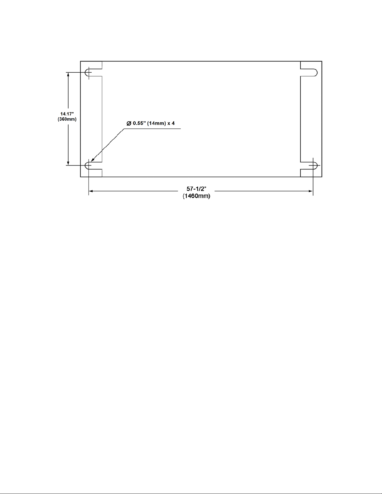
7.1 Hole center dimensions
Figure 2
7.2 Unpacking
Open shipping container and check for shipping
damage. Report any damage immediately to
your distributor and shipping agent. Do not
discard any shipping m aterial until the Shear is
assembled and running properly.
Compare the contents of your container w ith the
following list to make sure all parts are intact.
Missing parts, if any, shoul d be reported to your
distributor. Read the instruction manual
thoroughly for assembly, maintenance and
safety instructions.
Contents of the Shipping Container
1 Hydraulic Shear with Foot Pedal
2 Front Arm Extensions
1 Front Stop, with hardware
1 Rear Stop, with hardware
2 Scale Rods
2 Adjusting Block Assemblies
1 Bevel Gauge, with hardware
1 Instructions and Parts Manual
1 Warranty Card
1. Remove the crating material from around
the machine.
2. Clean the protec tant from all exp osed metal
surfaces with a mild solvent or kerosene,
and a soft rag. Do not use lacquer thinner,
paint thinner, or gasoline, as these may
damage painted surfaces.
3. Coat all machined surf aces with a light coat
of oil to inhibit rust.
4. Remove the bolts holding the machine to the
skid.
5. Place straps below the table (you may have
to remove front cover), and use properly
rated lifting equipm ent to move the machine
to a level foundation. Mac hine location m ust
allow access to all sides . Use shims at f loor
if needed.
Assembly Note: Prior to shipment, the
hydraulic shear is adjusted at the factory for
proper alignments and op eration. If the m achine
does not operate properl y or the stand does not
sit squarely on the floor, pr oc eed to Adjustments.
6. When the machine sits evenly, secure it to
the floor using proper fasteners. Refer to
Figure 2.
7.3 Stop assemblies
Refer to Figure 1.
1. Attach the two front arm extensions (3) to
the bed with four hex cap screws and four
washers. Level arm extension surfaces with
the table before tightening.
8
Page 9
2. Attach front stop (9) to f ront arm extensions
Extension Cord Length *
25
50
75
100
150
200
< 5
16
16
16
14
12
12
5 to 8
16
16
14
12
10
NR
8 to 12
14
14
12
10
NR
NR
12 to 15
12
12
10
10
NR
NR
15 to 20
10
10
10
NR
NR
NR
21 to 30
10
NR
NR
NR
NR
NR
with T-screws and wing nuts.
3. Attach rear stop (17) to the Adjusting Block
(14) with six hex cap screws and six flat
washers.
4. Insert a scale rod (13) through each
adjusting block as s em bl y and into c ut ter bar .
The scales must face up.
7.4 Electrical connections
Recommended Gauges (AWG) of Extension Cords
Amps
feet
feet
feet
feet
feet
feet
Electrical connections must
be made by a qualified electrician in
compliance with all relevant codes. This
machine must be properly grounded to help
prevent electrical shock and possible fatal
injury.
7.4.1 Grounding instructions
This machine m ust be grounded . In the event of
a malfunction or bre akdown, gro unding prov ides
a path of least res istance for electric current to
reduce the risk of electric shock.
Improper connection of the equipmentgrounding conductor can result in a risk of
electric shock. The conductor with insulation
having an outer surface that is green with or
without yellow stripes, is the equipmentgrounding conductor. I f repair or r eplacem ent of
the electric cord or plug is necessary, do not
connect the equipment-grounding conductor to a
live terminal.
Check with a qualified electrician or service
personnel if the grounding instructions are not
completely understood, or if in doubt as to
whether the tool is pr operly grounded . Repair or
replace a damaged or worn cord immediately.
7.4.2 Extension cords
The use of an extension cord is not
recommended. Try to place shop equipment
within reach of th e po w er source. If an ex tension
cord becomes necessary, make sure the cord
rating is suitable for the amperage listed on the
machine’s motor plate. An undersized cord will
cause a drop in line voltag e resulting in loss of
power and overheating.
*based on limiting the line voltage drop to 5V at 150% of the
rated amperes.
NR: Not Recommended.
Table 1
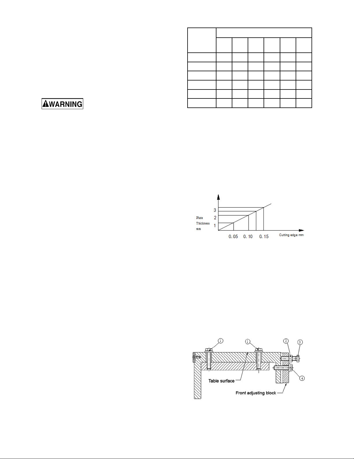
8.0 Adjustments
8.1 Adjustment for the shearing edge
gap
The relationship between plate thickness and
cutting edge data is shown in Figure 3.
Figure 3
To adjust gap (Figure 4):
1. Loosen bolts (1,2,3).
2. Tighten bolt (4) to increas e gap. Loos en bolt
(4) and tighten bolt (3) to decrease gap.
NOTE: Adjust equally at both ends of
machine.
3. Check gap with feeler gauge.
4. When gap value and shear plate thickness
correspond, tighten nut (2) and bolts (1).
Use the chart in Figure 17 as a gener al guide i n
choosing the correct size cord. If in doubt, use
the next heavier gaug e. The smaller the gauge
number, the heavier the cord.
Figure 4
9
Page 10

8.2 Adjustment for back gauge
9.0 Maintenance
Position rear stop to “ 0” on the scales, and v erify
that stop plate is par allel to shear. If not, lo osen
screw (1) and rotate nut (2) until aligned.
Retighten screw (1).
To adjust rear stop f or operations, loosen ha ndle
(4) and rotate handwheel (5) until desired
measurement is reached. Lock handle (4).
Figur e 5
Use care when working with
or around the knives.
The 2-way upper knife can be removed and
flipped 180°, for a new e dge before ha ving to be
sharpened.
Wipe the blades lightly with oil.
Lubricate all pivot points on the machine daily.
10.0 Troubleshooting the HS-1452
Trouble Probable Cause Remedy
Incorrect gap between blades. Increase gap for thicker gauge metals.
Blades will not cut
material.
Unsatisfactory cuts.
Cuts not square.
Material exceeds machine cap acity . Stay within capacity.
Blades are dull. Replace or sharpen blades.
Blades dull. Replace or sharpen blades.
Incorrect gap between blades. Correct gap.
Loose gibs. Remove backlash from gibs.
Inadequate hold-down pressure. Adjust pressure of hold-down.
Blade gap unequal. Adjust gap equally across length of blade.
Uneven guide contact. Place work against guide consistently.
Table 2
11.0 Replacement Parts
Replacement parts ar e listed on the fol lowing pag es. To order par ts or reach our service de partm ent, call
1-800-274-6848, Mond ay thr ough Frida y (see our webs ite for bus iness ho urs, www.jettools.com). Having
the Model Number and Ser ial Num ber of your mac hine avail able whe n you cal l will allow us t o ser ve you
quickly and accurately.
10
Page 11

11.1.1 HS-1452 Hydraulic Shear – Exploded View
11
Page 12

11.1.2 HS-1452 Rear Stop and Press Plate – Exploded View
12
Page 13

11.1.3 HS-1452 Hydraulic Regulator Assembly – Exploded View
226
225
228
227
231
207
210
219
203
204
205
201
202
206
210
213
214
215
210
210
213
214
215
210
69
43
216
217
218
220
211
211
210
209
208
210
223
222
227
228
224
232
230
229
233
69
43
221
13
Page 14

121
122
123
124
126
132
127
128
129
130
125
131
11.1.4 HS-1452 Control Box – Exploded View
14
Page 15

11.1.5 HS-1452 Hydraulic Shear Assembly – Parts List
Index No. Part No. Description Size Qty
1 ................ HS1252-1 ............... Cover.................................................................... ............................................. 1
2 ................ TS-1550041 ........... Flat Washer .......................................................... M6 ........................................ 7
3 ................ TS-2246122 ........... Hex Socket Button Head Screw ........................... M6x12 .................................. 7
4 ................ HS1252-4 ............... Copper Nut ........................................................... M12 ...................................... 2
5 ................ HS1252-5 ............... Copper Bolt .......................................................... M12x70 ................................ 2
6 ................ HS1252-6 ............... Upper Beam ......................................................... ............................................. 1
7 ................ HS1252-7 ............... Fixed Plate ........................................................... ............................................. 2
8 ................ HS1252-8 ............... Block .................................................................... ............................................. 8
9 ................ TS-1533032 ........... Cross Recess Head Screw ................................. M5x10 ................................ 16
10 .............. HS1252-10 ............. Fixed Plate ........................................................... ............................................. 2
11 .............. HS1252-11 ............. Blade .................................................................... ............................................. 2
12 .............. HS1252-12 ............. Bolt ....................................................................... M6x12 ................................ 28
13 .............. TS-1510071 ........... Hex Cap Screw .................................................... M16x70 ................................ 4
14 .............. HS1252-14 ............. Washer ................................................................. ............................................. 4
15 .............. HS1252-15 ............. Scale .................................................................... ............................................. 1
16 .............. HS1252-16 ............. Table .................................................................... ............................................. 1
17 .............. HS1252-17 ............. Support Rod ......................................................... ............................................. 2
18 .............. TS-1505031 ........... Socket Head Cap Screw ...................................... M10x25 ................................ 4
19 .............. TS-1550061 ........... Flat Washer .......................................................... M8 ........................................ 4
20 .............. TS-1490021 ........... Hex Cap Screw .................................................... M8x16 .................................. 4
21 .............. HS1252-21 ............. Scale .................................................................... ............................................. 1
22 .............. TS-149105 ............. Hex Cap Screw .................................................... M10x35 ................................ 4
23 .............. TS-1550071 ........... Flat Washer .......................................................... M10 ...................................... 4
24 .............. TS-1491041 ........... Hex Cap Screw .................................................... M10x30 ................................ 4
25 .............. TS-2279301 ........... Hex Socket Set Screw ......................................... M10x30 ................................ 2
26 .............. TS-2311101 ........... Hex Nut ................................................................ M10 ...................................... 2
27 .............. HS1252-27 ............. Upper Limit Block (RH) ........................................ ............................................. 1
28 .............. HS1252-28 ............. Upper Support ...................................................... ............................................. 1
29 .............. TS-2210501 ........... Hex Cap Screw .................................................... M10x50 .............................. 12
30 .............. TS-2311101 ........... Hex Nut ................................................................ M10 ...................................... 8
31 .............. TS-1550071 ........... Flat Washer .......................................................... M10 ...................................... 4
32 .............. HS1252-32 ............. Rear Plate ............................................................ ............................................. 1
33 .............. TS-1550041 ........... Flat Washer .......................................................... M6 ........................................ 6
34 .............. TS-2246122 ........... Hex Socket B utton Head Screw ........................... M6x12 .................................. 6
35 .............. HS1252-35 ............. Upper Limit Block (LH) ......................................... ............................................. 1
36 .............. TS-1504041 ........... Socket Head Cap Sc rew ...................................... M8x20 .................................. 4
37 .............. HS1252-37 ............. Body ..................................................................... ............................................. 1
38 .............. HS1252-38 ............. Block .................................................................... ............................................. 2
39 .............. TS-1523051 ........... Hex Socket Set Screw ......................................... M6x16 .................................. 2
40 .............. TS-2310201 ........... Hex Nut ................................................................ M20 ...................................... 2
41 .............. HS1252-41 ............. Lower Connecting Block ...................................... ............................................. 2
42 .............. HS1252-42 ............. Pin ........................................................................ ............................................. 2
43 .............. HS1252-43 ............. Cylinder Adaptor .................................................. ............................................. 2
44 .............. HS1252-44 ............. Clevis Pin ............................................................. ............................................. 2
45 .............. HS1252-45 ............. Cotter Pin ............................................................. 3.2x45 .................................. 8
46 .............. HS1252-46 ............. Connecting bar ..................................................... ............................................. 1
47 .............. HS1252-47 ............. Clevis Pin ............................................................. ............................................. 2
48 .............. HS1252-48 ............. Link Rod ............................................................... ............................................. 2
49 .............. TS-2310201 ........... Hex Nut ................................................................ M20 ...................................... 2
50 .............. HS1252-50 ............. Upper Connecting Block ...................................... ............................................. 2
51 .............. HS1252-51 ............. Clevis Pin ............................................................. ............................................. 2
52 .............. HS1252-52 ............. Lower Limit Switch ............................................... ............................................. 1
53 .............. HS1252-53 ............. Adjusting Block..................................................... ............................................. 1
54 .............. HS1252-54 ............. Upper Limit Switch ............................................... ............................................. 1
55 .............. HS1252-55 ............. Stand for Limit Switch .......................................... ............................................. 2
56 .............. TS-1503031 ........... Socket Head Cap Screw ...................................... M6x12 .................................. 4
57 .............. TS-1550041 ........... Flat Washer .......................................................... M6 ........................................ 4
58 .............. HS1252-58 ............. Adjusting Block..................................................... ............................................. 1
15
Page 16

Index No. Part No. Description Size Qty
59 .............. TS-1505031 ........... Socket Head Cap Screw ...................................... M10x25 ................................ 6
60 .............. TS-2311101 ........... Hex Nut ................................................................ M10 ...................................... 2
61 .............. TS-2210451 ........... Hex Cap Screw .................................................... M10x45 ................................ 2
62 .............. HS1252-62 ............. Stand for Electric Box........................................... ............................................. 1
63 .............. TS-1503031 ........... Socket Head Cap Screw ...................................... M6x12 .................................. 4
64 .............. HS1252-64 ............. Electric Box .......................................................... ............................................. 1
65 .............. TS-1503081 ........... Socket Head Cap Screw ...................................... M6x35 .................................. 4
66 .............. HS1252-66 ............. Electric Box Bolt ................................................... ............................................. 4
67 .............. HS1252-67 ............. Electric Box Cover................................................ ............................................. 1
68 .............. HS1252-68 ............. Clevis Pin ............................................................. ............................................. 2
69 .............. HS1252-69 ............. Cylinder ................................................................ ............................................. 2
70 .............. HS1252-70 ............. Screw ................................................................... ST4.2x45 ............................. 4
71 .............. HS1252-71 ............. Select Switch........................................................ XB2-ED23 ............................ 1
72 .............. TS-1532042 ........... Cross Recess Head Screw .................................. M4x12 .................................. 4
73 .............. HS1252-73 ............. Switch Box ........................................................... ............................................. 1
74 .............. HS1252-74 ............. Post ...................................................................... ............................................. 1
75 .............. HS1252-75 ............. Pedal Guard ......................................................... YBLT-YDT1/11 .................... 1
76 .............. TS-1501041 ........... Socket Head Cap Screw ...................................... M4x12 .................................. 4
77 .............. HS1252-77 ............. Pedal Switch ........................................................ YBLT-YDT1/11 .................... 1
78 .............. HS1252-78 ............. Strain Relief.......................................................... M20x1.5 ............................... 1
80 .............. TS-2246122 ........... Hex Socket B utton Head Screw ........................... M6x12 .................................. 8
81 .............. TS-1550041 ........... Flat Washer .......................................................... M6 ........................................ 8
82 .............. HS1252-82 ............. Front Plate............................................................ ............................................. 1
83 .............. HS1252-83 ............. Nut........................................................................ M12 ...................................... 2
84 .............. TS-1521021 ........... Hex Socket S et Screw ......................................... M4x6 .................................... 2
85 .............. TS-1505061 ........... Socket Head Cap Screw ...................................... M10x40 ................................ 2
86 .............. TS-2361101 ........... Lock Washer ........................................................ M10 ...................................... 2
87 .............. TS-1550071 ........... Flat Washer .......................................................... M10 ...................................... 2
88 .............. HS1252-88 ............. Block .................................................................... ............................................. 2
89 .............. HS1252-89 ............. Coiled Spring........................................................ 25x12.5x1.5 ....................... 48
90 .............. HS1252-90 ............. Rod....................................................................... ............................................. 2
91 .............. TS-1503071 ........... Socket Head Cap Screw ...................................... M6x30 .................................. 2
92 .............. HS1252-92 ............. Hold-down ............................................................ ............................................. 1
93 .............. HS1252-93 ............. Guide Slot (RH) .................................................... ............................................. 1
94 .............. HS1252-94 ............. Rubber Seal ......................................................... ............................................. 1
95 .............. TS-1504071 ........... Socket Head Cap Screw ...................................... M8x35 .................................. 4
96 .............. HS1252-96 ............. Guide Slot (LH) .................................................... ............................................. 1
97 .............. HS1252-97 ............. Socket Head Cap Screw ...................................... M8x20 .................................. 4
98 .............. HS1252-98 ............. Washer ................................................................. ............................................. 6
99 .............. HS1252-99 ............. Scale .................................................................... ............................................. 2
100 ............ HS1252-100 ........... Scale Rod............................................................. ............................................. 2
101 ............ HS1252-101 ........... Retaining Ring...................................................... 37 ......................................... 4
102 ............ HS1252-102 ........... Bearing (37x25x7) ................................................ 61805 ................................... 4
103 ............ HS1252-103 ........... Small Gear ........................................................... ............................................. 2
104 ............ TS-1522011 ........... Hex Socket Set Screw ......................................... M5x6 .................................... 2
105 ............ HS1252-105 ........... Ring ...................................................................... ............................................. 2
106 ............ HS1252-106 ........... Connecting Bar .................................................... ............................................. 1
107 ............ HS1252-107 ........... Flat Key ................................................................ 5x20 ..................................... 2
108 ............ HS1252-108 ........... Block .................................................................... ............................................. 2
109 ............ TS-1504081 ........... Socket Head Cap Sc rew ...................................... M8x40 .................................. 2
110 ............ HS1252-110 ........... Sliding Bushing .................................................... ............................................. 4
111 ............ HS1252-111 ........... Sliding Block......................................................... ............................................. 2
112 ............ HS1252-112 ........... Adjustable Handle ................................................ M10x50 ................................ 2
113 ............ HS1252-113 ........... Spacer .................................................................. ............................................. 2
114 ............ HS1252-114 ........... Nut........................................................................ M20x1.5 ............................... 2
115 ............ HS1252-115 ........... Fixed Shaft ........................................................... ............................................. 2
116 ............ HS1252-116 ........... Rear Stop ............................................................. ............................................. 1
117 ............ TS-1550061 ........... Flat Washer .......................................................... M8 ........................................ 2
118 ............ TS-1490031 ........... Hex Cap Screw .................................................... M8x20 .................................. 2
119 ............ HS1252-119 ........... Handwheel ........................................................... Φ150xΦ16 ........................... 1
120 ............ TS-2276081 ........... Hex Socket Set Screw ......................................... M6x8 .................................... 1
121 ............ HS1252-121 ........... Cable for Limit Switch .......................................... 2x0.75mm² ........................... 1
16
Page 17

Index No. Part No. Description Size Qty
122 ............ HS1252-122 ........... Cable for Magnetic Valve ..................................... 6x0.5mm² 1.5m ................... 1
123 ............ HS1252-123 ........... Power Cable (for 1PH) ......................................... 3x2.5mm² ............................. 1
.................. HS1252-123/3 ........ Power Cable (for 3PH) ......................................... 4x1.5mm² ........................... 1
124 ............ HS1252-124 ........... Control Cable ....................................................... 6x0.5mm² 2.5m ................... 1
125 ............ HS1252-125 ........... Strain Relief.......................................................... M16x1.5 ............................... 3
126 ............ HS1252-126 ........... Slave Relay .......................................................... HH54P ................................. 2
127 ............ HS1252-127 ........... Transformer (for 1PH) .......................................... ............................................. 1
.................. HS1252-127/3 ........ Transformer (for 3PH) .......................................... ............................................. 1
128 ............ HS1252-128 ........... Time Relay ........................................................... JS14P 0.1-0.99S ................. 1
129 ............ HS1252-129 ........... Breaker (for 1PH) ................................................. DZ47-63 1P C5/2P C16 ....... 1
.................. HS1252-129/3 ........ Breaker (for 3PH) ................................................. DZ47-63 1P C5/3P C10 ....... 1
130 ............ HS1252-130 ........... A.C. Contactor (for 1PH) ...................................... CU11 AC24V ...................... 1
.................. HS1252-130/3 ........ A.C. Contactor (for 3PH) ...................................... CN-6 AC24V ....................... 1
131 ............ HS1252-131 ........... Thermal Relay (for 1PH) ...................................... RHN-10 17-8.5… ................. 1
.................. HS1252-131/3 ........ Thermal Relay (for 3PH) ...................................... RHN-5M 5.5-8.5................... 1
132 ............ HS1252-132 ........... Junction Terminal ................................................. UK3N 10A ............................ 1
200 ............ HS1252-200 ........... Hydraulic Station .................................................. ............................................. 1
201. ........... HS1252-201 ........... Oil Tank ................................................................ 50L ....................................... 1
202 ............ HS1252-202 ........... Oil Gauge ............................................................. LS-50 ................................... 1
203 ............ HS1252-203 ........... Filter ..................................................................... JL-04 ................................... 1
204 ............ HS1252-204 ........... Filter Cap.............................................................. JY-50 .................................. 1
205 ............ HS1252-205 ........... Cover.................................................................... ............................................ 1
206 ............ TS-1482041 ........... Hex Cap Screw .................................................... M6x20 ................................. 8
207 ............ HS1252-207 ........... Oil Return Hose.................................................... ............................................ 2
208 ............ HS1252-208 ........... Regulating Valve .................................................. Y1 3/4-16UNF ................... 1
209 ............ HS1252-209 ........... Block .................................................................... ............................................ 1
210 ............ HS1252-210 ........... Straight Fitting ...................................................... M16x1.5 ............................... 8
211 ............ HS1252-211 ........... Hydraulic Hose ..................................................... Φ18x300mm ....................... 2
213 ............ HS1252-213 ........... Hydraulic Hose ..................................................... Φ18x430mm ....................... 2
214 ............ HS1252-214 ........... T-Fitting ................................................................ M16x1.5 .............................. 2
215 ............ HS1252-215 ........... Hydraulic Hose ..................................................... Φ18x930mm ....................... 2
216. ........... HS1252-216 ........... Socket Head Cap Screw ...................................... M5X100 .............................. 4
217 ............ HS1252-217 ........... Magnetic Valve..................................................... DSG-02-3C6 ....................... 1
218. ........... HS1252-218 ........... Hydraulic switch ................................................... ............................................ 1
219 ............ HS1252-219 ........... Valve .................................................................... D1 3/416UNF ...................... 1
220 ............ HS1252-220 ........... Hydraulic Pressure Gauge ................................... ............................................. 1
221 ............ HS1252-221 ........... Gauge Switch ....................................................... ............................................. 1
222 ............ HS1252-222 ........... Hydraulic Hose ..................................................... ............................................. 1
223 ............ HS1252-223 ........... Motor .................................................................... 2.2kW 1PH........................... 1
.................. HS1252-223/3 ........ Motor .................................................................... 2.2kW 3PH........................... 1
224 ............ TS-1490051 ........... Hex Cap Screw .................................................... M8x30 .................................. 4
225 ............ HS1252-225 ........... Hydraulic Hose ..................................................... ............................................. 1
226 ............ HS1252-210 ........... Straight Fitting ...................................................... M16x1.5 ............................... 1
227 ............ HS1252-227 ........... Screw ................................................................... M6x25 .................................. 8
228 ............ HS1252-228 ........... Connect Block ...................................................... ............................................. 2
229 ............ HS1252-229 ........... Hydraulic pump ……….. ...................................... RGP-2A-F11R ..................... 1
230 ............ HS1252-230 ........... Socket Head Cap Screw ...................................... M10x25 ................................ 4
231 ............ HS1252-210 ........... Straight Fitting ...................................................... M16x1.5 ............................... 1
232 ............ HS1252-232 ........... Filter ..................................................................... ............................................. 1
233 ............ HS1252-233 ........... Hex Bolt................................................................ M8x30 .................................. 4
234 ............ TS-1505031 ........... Socket Head Cap Sc rew ...................................... M10x25 ................................ 3
235 ............ TS-1550071 ........... Flat Washer .......................................................... M10 ...................................... 3
236 ............ HS1252-236 ........... Front Stop ............................................................ ............................................. 1
237 ............ HS1252-237 ........... Bevel Gauge ........................................................ ............................................. 1
238 ............ HS1252-238 ........... T-Nut .................................................................... ............................................. 3
239 ............ HS1252-239 ........... Plug ...................................................................... ............................................. 2
17
Page 18
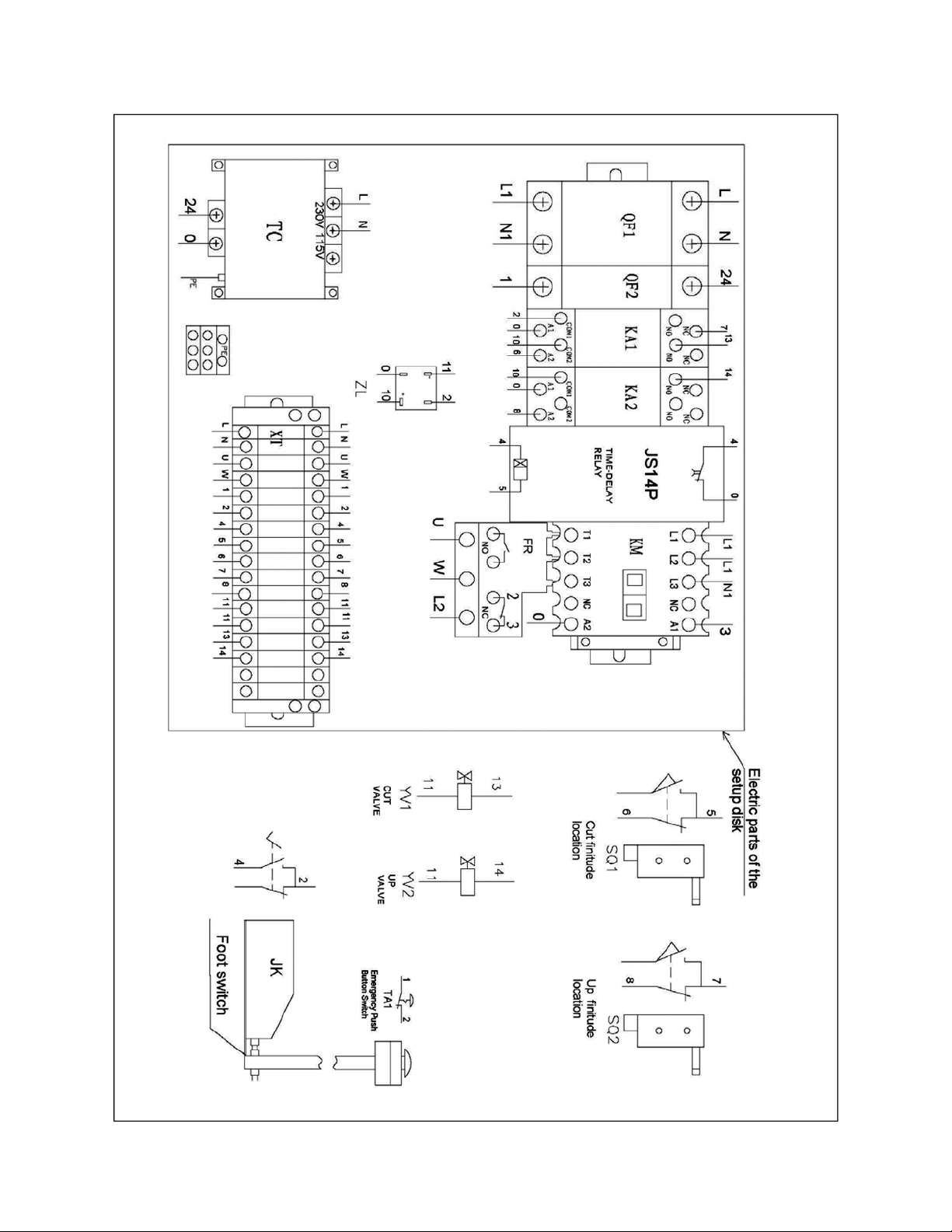
12.1 Electrical Connections – single phase only (HS-1452)
18
Page 19

19
Page 20

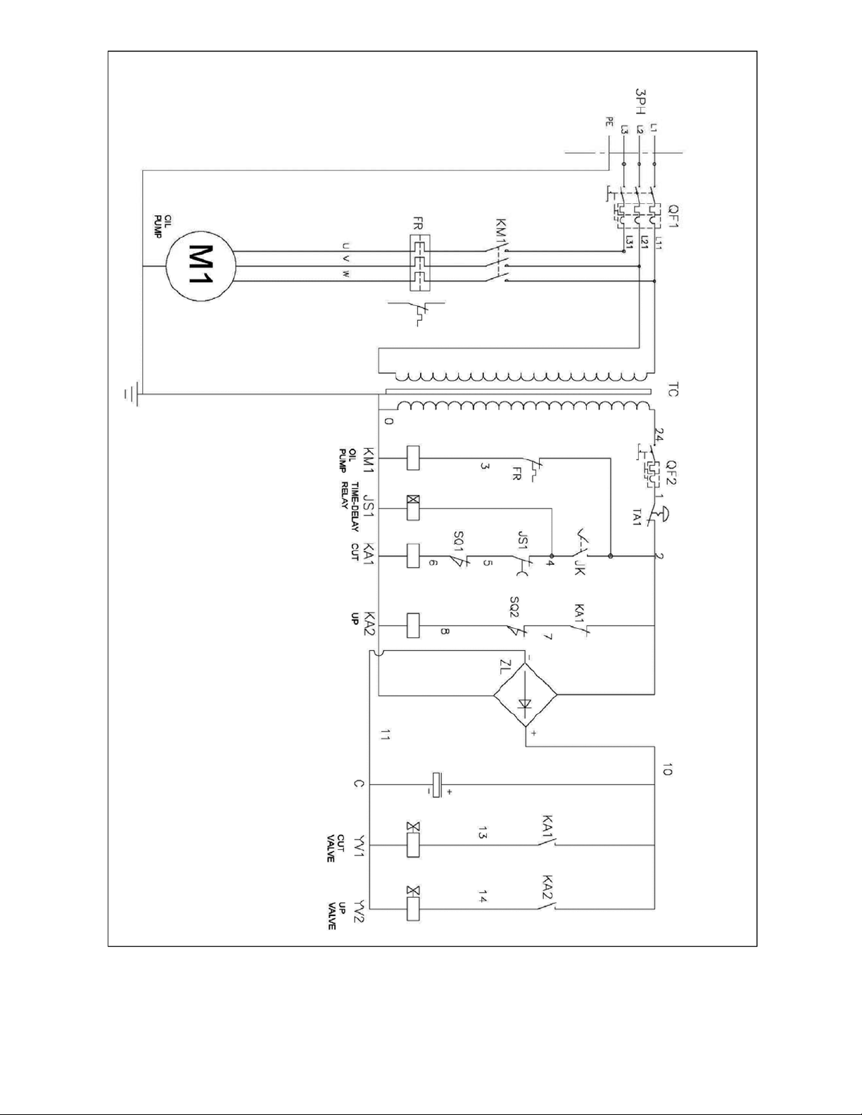
12.2 Electrical Connections – 3 phase only (HS-1452)
20
Page 21
21
Page 22

13.0 Hydraulic diagram (HS-1452)
No. Description Qty
1 Hydraulic tank 1
2 Oil filter 1
3 Air filter 1
4 Oil gauge 1
5 Motor 1
6 Pump 1
7 Pressure regulating valve 1
8 One way valve 1
9 Pressure indicator 1
10 Indictor switch 1
11 Magnetic exchange valve 1
12 Cylinder 2
22
Page 23

This page intentionally left blank
23
Page 24

427 New Sanford Road
LaVergne, Tennessee 37086
Phone: 800-274-6848
www.jettools.com
24
 Loading...