

Page 1
This .pdf document is bookmarked
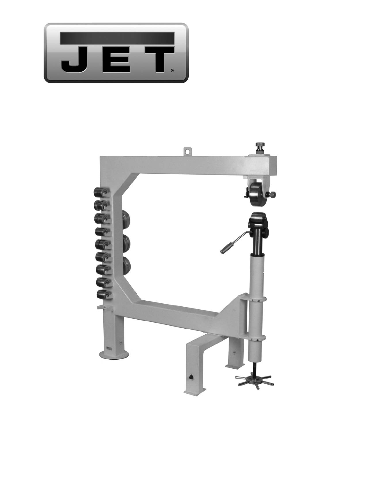
Operating Instructions and Parts Manual
45-inch English Wheel
Model: WH-45T
JET
427 New Sanford Road
LaVergne, Tennessee 30786 Part No. M-756151
Ph.: 800-274-6848 Revision A1 05/2014
www.jettools.com Copyright © 2014 JET
Page 2

Warranty and Service
JET® warrants ev ery prod uct it sell s aga inst m anufact urers’ def ects. I f one of our tools needs service or repa i r, pleas e
contact Technical Service by calling 1-800-274-6846, 8AM to 5PM CST, Monday through Friday.
Warranty Period
The general warranty lasts for the time period specified in the literature included with your product or on the official
JET branded website.
• JET products carry a limited warranty which varies in duration based upon the product. (See chart below)
• Accessories carry a limited warranty of one year from the date of receipt.
• Consumable items are defined as expendable parts or accessories expected to become inoperable within a
reasonable amount of use and are covered by a 90 day limited warranty against manufacturer’s defects.
Who is Covered
This warranty covers only the initial purchaser of the product from the date of delivery.
What is Co vered
This warranty covers any defects in workmanship or materials subject to the limitations stated below. This warranty
does not cover failures due directly or indirectly to misuse, abuse, negligence or accidents, normal wear-and-tear,
improper repair, alterations or lack of maintenance.
Warranty Limitations
Woodworking products with a Five Year Warranty that are used for commercial or industrial purposes default to a
Two Year Warranty. Please contact Technical Service at 1-800-274-6846 for further clarification.
How to Get Technical Support
Please contact Technical Service by calling 1-800-274-6846. Please note that you will be asked to pro vi d e pr o of
of initia l p u rch a s e whe n calling. If a product requires further inspection, the Technical Service representative will
explain and assist with any additional action needed. JET has Authorized Service Centers located throughout the
United States. For the name of an Authorized Service Center in your area call 1-800-274-6846 or use the Service
Center Locator on the JET website.
More Information
JET is constantly adding new products. For complete, up-to-date product information, check with your local distributor
or visit the JET website.
How S tat e Law A pplies
This warranty gives you specific legal rights, subject to applicable state law.
Limitations on This Warranty
JET LIMITS ALL IMPLIED WARRANTIES TO THE PERIOD OF THE LIMITED WARRANTY FOR EACH PRODUCT.
EXCEPT AS STATED HEREIN, ANY IMPLIED WARRANTI ES OF MERCHANTABILITY AND FITNESS FOR A
PARTICULAR PURPOSE ARE EXCLUDED. SOME STATES DO NOT ALLOW LIMITATIONS ON HOW LONG AN
IMPLIED WARRANTY LASTS, SO THE ABOVE LIMITATION MAY NOT APPLY TO YOU.
JET SHALL IN NO EVENT BE LIABLE FOR DEATH, INJURIES TO PERSONS OR PROPERTY, OR FOR
INCIDENTAL, CONTINGENT, SPECIAL, OR CONSEQUENTIAL DAMAGES ARISING FROM THE USE OF OUR
PRODUCTS. SOME STATES DO NOT ALLOW THE EXCLUSION OR LIMITATION OF INCIDENTAL OR
CONSEQUENTIAL DAMAGES, SO THE ABOVE LIMITATION OR EXCLUSION MAY NOT APPLY TO YOU.
JET sells through distributors only. The specifications listed in JET printed materials and on official JET website are
given as general information and are not binding. JET reserves the right to effect at any time, without prior notice,
those alterations to parts, fittings, and accessory equipment which they may deem necessary for any reason
whatsoever. JET
Product Listing with Warranty Period
90 Days – Parts; Consumable items; Light-Duty Air Tools
1 Year – Motors; Machine Accessories; Heavy-Duty Air Tools; Pro-Duty Air Tools
2 Year – Metalworking Machinery; Electric Hoists, Electric Hoist Accessories
5 Year – Woodworking Machinery
Limited Lifetime – JET Parallel clamps; VOLT Series Electric Hoists; Manual Hoists; Manual Hoist
Accessories; Shop Tools; Warehouse & Dock products; Hand Tools
NOTE: JET is a division of JPW Industries, Inc. References in this document to JET also apply to JPW Industries,
Inc., or any of its successors in interest to the JET brand.
®
branded products are not sold in Canada by JPW Industries, Inc.
2
Page 3

Table of Contents
Warranty and Servic e .............................................................................................................................. 2
Table of Contents .................................................................................................................................... 3
Warnings ................................................................................................................................................. 4
Introduction ............................................................................................................................................. 6
Specifica tions ................................................................................................................ .......................... 6
Unpacking and Setup .............................................................................................................................. 7
Cleanup ............................................................................................................................................... 7
Site Considerations .............................................................................................................................. 7
Moving the English Wheel .................................................................................................................... 7
Securing t o Floor .................................................................................................................................. 7
Operation ................................................................................................................................................ 7
Overview.............................................................................................................................................. 7
Basic Operati ons .................................................................................................................................. 8
Adjustments ................................................................................................................... ......................... 8
Replacin g th e Whe el ............................................................................................................................ 8
Rotating Wheels................................................................................................................................... 9
Rolling Tip s ........................................................................................................................................ 10
Adjusting the Quick Release Lever ..................................................................................................... 10
Wheel Alig nment ................................................................................................................................ 10
Lubrication............................................................................................................................................. 11
Troubleshooting the WH-45T English Wheel .......................................................................................... 12
Parts ..................................................................................................................................................... 12
Ordering Replacement Parts .............................................................................................................. 12
Assembly Drawing f or WH-45T English Wheel ................................................................................... 13
Parts Lis t for WH-45T English Wheel.................................................................................................. 14
Wheel Chart ....................................................................................................................................... 16
The specifications in this manual ar e given as general i nformation and are not binding. JET, reserves the
right to eff ect, at any tim e and wit hout pri or notic e, changes or alt erat ions to par ts, fi tti ngs, and accessory
equipment deemed nec essary for any reason whatsoever.
3
Page 4

Warnings
1. Read and understand the ent ire owner’s manual bef or e att em pting assembly or operation.
2. Read and understand the warnings po sted on the m achine and i n thi s manual. Fail ure to comply wit h
all of these warnings m ay cause seriou s i njury.
3. Replace warning l abels if they become obscured or removed.
4. This English wheel i s designed and intended for use by properl y trained and experienced per sonnel
only. If y ou are not familiar with t he proper and safe operat ion of an English wheel , do not use until
proper trai ning and k nowledge have been obtai ned.
5. Do not use this English wheel for other than its intended use. If used for other purposes, JET
disclaim s any real or i mplied warrant y and h olds itsel f harml ess from any injury t hat may r esult f rom
that use.
6. Always wear approved safety glasses/face shields while using this English wheel. Everyday
eyeglasses only have impact resistant lenses; they are not safet y gl asses.
7. Bef or e operati ng this Engli sh wheel, remov e tie, rings, watches and other jewelr y, and r oll sleev es up
past the elbows. Rem ove all loose cl othing and confi ne long hair. Non-sl ip foot wear or anti-ski d floor
strips are recommended.
8. Some dust created by power sanding, sawing, grinding, drilling and other construction activities
contain chemi cals known to cause cancer , bir th defects or other r eproductiv e harm . Some exampl es
of these chemic als are:
• Lead from lead based paint.
• Crystalli ne sil ic a from bricks, cement and other m asonry pr oduc ts.
• Arsenic and chromium from chemically treated lum ber.
Your risk of exposure varies, depending on how often you do this type of work. To reduce your
exposure to these chemicals, work in a well-ventilated area and work with approved safety
equipment, such as face or dust masks that are specifically designed to filter out microscopic
particles.
9. Do not operate this machine while tired or under the influence of drugs, alcohol or any m edic ation.
10. Remove adjusting keys and wrenches. Form a habit of checking to see that keys and adjusting
wrenches are removed from the machine before using.
11. Keep safety guards in place at all times when the machine is in use. If removed for maintenance
purposes, use extreme caution and replac e the guards immediately.
12. If possible, the English Wheel should be secured to the floor before use.
13. Check damaged parts. Before further use of the machine, a guard or other part that is damaged
should be carefully checked to determine that it will operate properly and perform its intended
function. Chec k for alignment of moving par ts, binding of moving parts, breakage of parts, mounting
and any other condi ti ons that m ay affect its operati on. A guard or ot her part that i s damaged should
be properly repaired or replaced.
14. Provide f or adequate space surrounding work area and non- glare, overhead lighting.
15. Keep the floor around the machine clean and free of scrap mater ial, oil and grease.
16. Keep visit or s a safe di stanc e from the work area. Keep children away.
17. Make your workshop chil d pr oof with padlocks, master switc hes or by removing starter k ey s.
18. Giv e your work undivi ded attention. Looki ng around, carryi ng on a conversati on and “horse-play” ar e
careless acts that can r esul t in serious injury.
19. Do not overreach. K eep pr oper footi ng and balance at all times.
4
Page 5

20. Use the right t ool at the cor rect feed rat e. Do not for ce a tool or attachm ent to do a j ob for which i t
was not designed. The right tool will do the job bett er and more safely .
21. Use recommended accessories; improper accessories may be hazardous.
22. M aintain tool s with care. Keep wheels clean f or best perform ance. Follow instructi ons for lubricating
and changing accessories.
23. Use leather glov es when handli ng steel work pieces.
24. Do not stand on the machine. S eri ous i njur y c oul d oc c ur if the mac hine tips over.
25. Remove loose it em s and unnecessary work pieces from the ar ea before using the machine.
Familiariz e you rself with the following safet y no tices used in this manual:
This means that if precautions are not heeded, it may result in minor injury and/or
possible machine damage.
This means that if precauti ons are not heeded, it may result in serious injury or possibly
even death.
5
Page 6

Introduction
This manual is provi ded by JET, covering the safe operation and mai ntenance procedures f or the JET
WH-45T English Wheel. This manual contains instructions on installation, safety precautions, general
operating proc edures, maintenance i nstructions and part s breakdown. This m achine has been designed
and constructed to pr ovi de years of troubl e free operation if used in accor dance wit h instructi ons set fort h
in this m anual. If there are any questi ons or com ments, please contact either y our local supplier or JET.
JET can also be reached at our web site: www.jettool s.com.
Specifications
Model ........................................................................................................................................... WH-45 T
Stock Number................................................................................................................................ 756151
Number of lower wheels provided .......................................................................................................... 10
Number of upper wheels prov ided ........................................................................................................... 4
Construction:
Frame .............................................................................. 4-3/4" square, 7-gauge gusseted steel tubing
Wheels .......................................................................................................................... hardened steel
Number of lower wheel storage holders ............................................................................................ 10
Number of upper wheel storage holders .............................................................................................. 3
Capacities:
Mild Steel ...................................................................................................................16 Gauge (0.06")
Aluminum ....................................................................................................................................... 1/8"
Copper .......................................................................................................................16 Gauge (0.05")
Dimensions:
Throat .............................................................................................................................................. 45"
Adjustment Post Diameter ......................................................................................................... 2-7/16"
Footprint ................................................................................................................................. 59" x 28"
Overall Dimensions, shipped.................................................................................. 67"L x 59" W x 15"H
Overall Dimensions, assembled ............................................................................. 56"L x 28" W x 63"H
Weights:
Shipping ................................................................................................................................... 555 lbs.
Net ........................................................................................................................................... 458 l bs.
The above specifications were current at the time this manual was published, but bec ause of our policy of
continuous impr ovement, JET reserves the r ight to change specifications at any t ime and without prior
notice, without incurring obligations.
Read and understand the entire contents of this manual before attempting
assembly or operat io n. Failure to comply may cause serious injury.
6
Page 7

Unpacking and Setup
Cleanup
Exposed metal surfaces, including upper and
lower wheels, are coated with a protectant to
resist corrosion during shipment. Remove this
coating wit h a soft rag and a solv ent or cl eanerdegreaser. Some parts may need to be removed
for thorough cleaning. Do not use gasoline,
acetone, lacquer thinner or other highly volatile
solvents, as these wil l damage painted surfaces.
Securing to Floor
Mounting the machine to the floor is strongly
recommended (floor mounting hardware is not
included). Lag shield anchors wit h lag bolts and
anchor studs are r ecom m ended for anchori ng t o
a concrete floor. Research mounting methods
and choose one that best fi ts your application.
Secure machine to the floor
to prevent instability and possible tipping
during operation.
Site Considerations
Floor Stability – Refer to the weight and foot print
specific ations f or t he machine. Resident ial fl oors
may require addi tional reinforcement to support
both machine and oper ator.
Operating Clearances – When establishing a
location f or your machine, consider existing and
anticipated needs, size of workpiece to be
processed, space for auxiliary stands, work
tables or other m ac hiner y that m ay be present.
To prevent personal injury,
do not allow unsupervised children or
visitors in your shop at any time!
Moving the English Wheel
The WH-45T is a heavy
machine. Get assistance when unpacking.
Retractable wheels beneath the main column
and support legs allow the machine to be moved
by one person. Rotate the three square head
bolts (Figure 1) with a wrench to lower or rai se
the wheels.
Operation
Overview
As the metal workpiece is rolled between the
upper wheel and lower wheel, it becomes longer
and thinner. At the same time, a trac k is pressed
into the metal, creating a convex curve in the
workpiece.
A variety of contours can be produced by
varying the amount and pattern of the tracks.
The English wheel can produce curves in mild
steel up to 16 gauge (0.06"), copper up to 16
gauge (0.05") and al umi num up to 1/ 8".
NOTE: Always retract the wheels before
operating the machine.
Figure 1
7
Page 8

Basic Operations
1. Cl ean the workpi ece and wheel s thoroughl y,
removing any grit or abrasive particles.
NOTE: Grit or dirt can mar the workpiece
and even damage the wheels.
De-burr sharp met al edges and wear l eather
gloves while handling sheet metal, to
prevent injury to your hands.
(G) rests against the bottom of the lower
wheel bracket (H).
Pinch Hazard! Do not place
fingers in wheel path du ring op erat io n.
Sharp metal edges can cause
lacerations. De-burr sharp edges and wear
leather gloves when handling.
Figure 3
5. Insert the workpiec e between the wheels.
Figure 2
Refer to Figure 2:
2. Turn the upper wheel knob (A) clockwise to
raise the upper wheel bracket (B) against
the frame as shown.
Note: Make sure the upper wheel bracket
(B) and frame block (C) edges are parallel
so that they slide past each other when
raising the upper wheel bracket. Otherwise,
they may bind.
3. Check the distance between bottom of the
upper wheel (D) and top of the lower w heel
(E). They should be about an i nch apart. To
adjust the distance, rotate the adjusting
wheel (shown in Figur e 10) to raise or lower
the lower wheel (E).
Refer to Figure 3:
4. Place the quick release lever (F) in the
engaged position to raise the lower wheel
(E) to the operating position. Engaged
position is where the flat edge on the cam
6. Rotate the adjusting wheel (sho wn in Figure
10) counter-clockwise until there is light
pressure on the workpiece.
7. Roll the workpiece up to an edge, rotate it
slightly then pull it back.
8. Turn the adjusting wheel counterclockwise
to increase pressure on t he workpiece; turn
the adjusting wheel clockwise to decrease
pressure.
Note: To reinsert a workpiece or insert
another workpiece of the same thickness,
use the quick release lever (F, Figure 3).
Adjustments
Replacing the Wheel
The JET Engli sh W heel i s provided wit h 4 upper
wheels and 10 lower wheels. Their profiles are
shown at the back of thi s manual.
Hold upper wheel securely
when inst alling or removi ng. Wear steel- toed
footwear for person al safet y.
To replace an upper wheel:
Refer to Figure 4.
1. Raise the lower wheel (E) until it contacts
the bottom of the upper wheel (D). This
ensures the upper wheel is supported.
8
Page 9

2. Flip up the lat ch (J) and slide out the upper
wheel axle (K) while holding the wheel.
Figure 4
Figure 5
To rotate lower wheel:
Refer to Figure 6.
1. Disengage quick release lever (F).
2. Remove lower wheel if needed for
clearance.
3. Lift the lower wheel assembly until the
knurled screw (L) reaches the top of the
groove in which it is currently positioned
).
(L
1
3. Carefully remove the upper wheel (D) and
set it on a bracket on the upper wheel r ac k .
4. Pl ace a new upper wheel i nt o position. Ali gn
the wheel bearing holes with the bracket
mounting holes, insert the axle (K), and
rotate the latch (J) to secure the wheel.
Note: Adjust the lower wheel height if you
need more clearance replacing the upper
wheel.
To replace a lower wheel :
1. Disengage the quick release lever (F, Figure
4) and lower the lower wheel bracket (H,
Figure 4) until t her e’s sufficient clearance.
2. Remove the lower wheel (E, Figure 4) and
replace it with another one.
3. Engage the quick release lever (F, Fig. 2)
and raise the lower wheel to the operating
position.
Rotating Wheels
The wheels can be positioned perpendicular to
the frame (A, Figure 5) for long workpieces or
parallel to the frame (B, Figure 5) for wide
workpieces.
Figure 6
4. Rotate the l ower wheel assembly, sliding the
knurled screw (L) along the entire distance
of the horizont al gr oov e ( L
).
2
5. Lower the lower w heel as se mbly until it rea ches
the bottom of the op pos ite groo ve (L
).
3
9
Page 10

To rotate upper whee l:
Refer to Figure 7.
6. Remove the lower wheel to provide clearance for the following steps.
7. Turn the upper wheel knob (A) counter-
clockwise to l ower the upper w heel bracket
(B) below the frame block (C).
8. Rotate the upper wheel 90 degrees (D), then
raise the upper wheel bracket (B) until it is
seated against the frame.
9. Reinstall lower wheel, engage the quick
release lever, and raise lower wheel to the
operating position.
Adjusting the Quick Release Lever
Refer to Figure 8:
The quick release lever is adjusted at the
factory. However, it may have become loose
during shipping. The set screws must engage
the lever to prev ent it from sli ppi ng.
To adjust the quic k release lever:
1. Examine the flats on the quick release lever.
Figure 8
Figure 7
Rolling Tips
Observe the following tips for successful
operation of the E nglish Wheel:
• Make sure workpiece and wheels are clean
and free of any debris.
• Start rolling sl owly , then increase speed.
• Try rolling the wheels up t o, but not pa st the
workpiece edge.
• Mark the workpiece with a non-permanent
marker to contour the metal or follow
tracking patterns.
• Use the lightest wheel pressure possible to
shape the workpiece. Too much pressure
will crease or rui n the metal.
• Use light pressure for smoothing, high
pressure for r ough shapi ng.
If a setscrew does not contac t a flat on the lever:
2. Use a hex wrench to l oosen the setscrews.
Turn the quick release lever so that the
setscrew is aligned wit h the f l at on the lever ,
then tighten t he setscrews.
Wheel Alignment
Wheel alignm ent can be a djusted by positi oning
the upper wheel with respect to the lower wheel.
Refer to Figure 9:
1. Loosen four setscrews (A) .
2. Determine the directi on that the upper wheel
should be shifted to align with the lower
wheel.
3. Turn the corresponding adjusting nut (B)
outward (counterclockwise) in small
incremental steps and the other adjusting
nut inward by the sam e amount.
4. Tighten the four setscrews(A).
10
Page 11

Figure 9
Lubrication
Refer to Figure 10:
The following ar eas should be kept lubricat ed:
Apply a coating of lithium grease to the cams (E )
where they contact the bottom of the lower
wheel bracket.
Pivot Points
Apply a small amount of oil, such as SAE 30W,
to the pivot points (F).
Wheels
When upper or lower wheels are not being used,
or are stored away, apply a light coat of oil to
prevent rust. Wipe off the oil before using the
wheels.
Upper wheel bracket (A)
Lower wheel bracket (B)
Jack screw (C)
Upper wheel axle (D)
Cams (E)
Pivot points (F)
Upper and Lower Wheel Brackets
Periodic ally lower the upper wheel bracket , and
apply a light coating of lit hium grease to the po st
(A).
Apply a light coating of oil, such as SAE 30W, to
the lower wheel bracket ( B ).
Jack Screw
Apply lithium grease as needed to the screw
threads (C).
Cams
Figure 10
11
Page 12

Troubleshooting the WH-45T English Wheel
Trouble Probable Cause Remedy
Quick release lever
will not engage, or
engages with
difficulty.
Upper wheel
swivels.
Wheel does not
shape workpiece.
Upper wheel
bracket will not seat
against frame.
Wheels form too
high a crown in
workpiece.
Wheels form too
low a crown
Lower wheel bracket and cams are
binding.
Setscrews on cams loose, not
contacting quick release lever flat s.
Upper wheel not secured t o frame
bracket.
Workpiec e too thi c k.
Crown is too low.
Incorrect pressure.
Upper wheel bracket catches on
frame block; surfaces are not parallel.
Lower wheel flat is too small. Use a lower wheel with a lar ger flat.
Lower wheel flat is too lar ge. Use a lower wheel with a smaller flat.
Lubricate c ontact points between top of
cams and bracket.
Align setscrews with lever flats and
tighten.
Turn upper wheel knob clockwise until
upper wheel bracket is snug against
frame bracket.
Use sheet metal of appropr iate
thick ness.
Use a lower wheel with a higher crown.
Increase pressure on workpi ec e.
Align upper wheel and upper f r am e
block surfaces when raising upper
wheel bra ck e t to fr ame.
Parts
Ordering Replacement Parts
To order parts or reach our service department, call 1-800-274-6848 Monday through Friday (see our
website for business hours, www.jettools.com). Having the Model Number and Serial Number of your
machine available when you call will allow us to serve you quickly and accurately.
12
Page 13

Assembly Drawing for WH-45T English Wheel
13
Page 14

Parts List for WH-45T English Wheel
Index No. Part No. Description Size Qty
1 ............... WH45T-1 .................Frame.................................................................................................... 1
1-1............ WH45 T-1-1 ..............Post Clamp ............................................................................................ 2
1-2............ WH45 T-1-2 ..............Frame Support Stand ............................................................................ 1
2 ............... WH45-2 ...................Collar .................................................................................................... 1
3 ............... WH45-3 ...................Adjustin g Lock Knob .............................................................................. 1
4 ............... WH45-4 ...................Washer............................................................................... ................... 1
5 ............... WH45-5 ...................Upper Wheel Shaft ................................................................................ 1
6 ............... WH45-6 ...................Short Pin ........................................................................... .................... 1
7 ............... WH45-7 ...................Position Block ........................................................................................ 1
8 ............... WH45-8 ...................Upper Wheel Housing............................................................................ 1
9 ............... WH45-9 ...................Inner Tube Adjusting Post ...................................................................... 1
9-2............ WH45- 9-2 ................Collar .................................................................................................... 1
10 ............. WH45-10 .................Outer Post ............................................................................................. 1
11 ............. WH45-11 .................Flange Bushi ng ..................................................................................... 1
12 ............. WH45-12 .................Lead Scr ew ........................................................................................... 1
13 ............. WH45-13 .................Lifting Lever ........................................................................................... 1
13-1 .......... WH45-13-1 ..............Cam ...................................................................................................... 2
13-2 .......... WH45-13-2 ..............Spacer................................................................................................... 2
13-3 .......... WH45-13-3 ..............Lifting Lever Handle ............................................................................... 1
15 ............. WH45-15 .................L o w e r Wheel Shaft .............................................................................. 10
16 ............. WH45-16 .................L o w e r Wheel Storage Bracket ............................................................. 1 0
17 ............. WH45-17 .................Upper Wheel Storage Bracket ............................................................... 3
18A .......... WH45-18 A ...............Lower Wheel 1 Assembly (Index #18, 15, 31) .....1/8” Edge ................... 1
18 ............. WH45-1 8 .................Lo wer Wheel 1 ...................................................................................... 1
19A .......... WH45-19 A ...............Lower Wheel 9 Assembly (Index #19, 15, 31) .....1/2" Ridged................. 1
19 ............. WH45-1 9 .................Lo wer Wheel 9 ...................................................................................... 1
20A .......... WH45-20 A ...............Lower Wheel 7 Assembly (Index #20, 15, 31) .....1/8" Ridged................. 1
20 ............. WH45-2 0 .................Lo wer Wheel 7 ...................................................................................... 1
21A .......... WH45-21 A ...............Lower Wheel 6 Assembly (Index #21, 15, 31) .....1/4" ............................ 1
21 ............. WH45-2 1 .................Lo wer Wheel 6 ...................................................................................... 1
22A .......... WH45-22 A ...............Lower Wheel 8 Assembly (Index #22, 15, 31) .....3/4" ............................ 1
22 ............. WH45-2 2 .................Lo wer Wheel 8 ...................................................................................... 1
23A .......... WH45-23 A ...............Lower Wheel 4 Assembly (Index #23, 15, 31) .....2-1/4” ......................... 1
23 ............. WH45-2 3 .................Lo wer Wheel 4 .......................................................................
24A .......... WH45-24 A ...............Lower Wheel 3 Assembly (Index #24, 15, 31) .....3/4" ............................ 1
24 ............. WH45-2 4 .................Lo wer Wheel 3 ...................................................................................... 1
25A .......... WH45-25 A ...............Lower Wheel 2 Assembly (Index #25, 15, 31) .....1-29/64” ...................... 1
25 ............. WH45-2 5 .................Lo wer Wheel 2 ...................................................................................... 1
26A .......... WH45-26 A ...............Lower Wheel 5 Assembly (Index #26, 15, 31) .....2-5/8" ......................... 1
26 ............. WH45-2 6 .................Lo wer Wheel 5 ...................................................................................... 1
27A .......... WH45-27 A ...............Upper Wheel 10 Assembl y (Index #27, 31) .........3/4" ............................ 1
27 ............. WH45-27 .................Upper Wheel 10 .................................................................................... 1
28A .......... WH45-28 A ...............Upper Wheel 11 Assembl y (Index #28, 31) .........1-29/64” ...................... 1
28 ............. WH45-28 .................Upper Wheel 11 .................................................................................... 1
29A .......... WH45-29 A ...............Upper Wheel 12 Assembl y (Index #29, 31) .........1/8” Edge ................... 1
29 ............. WH45-29 .................Upper Wheel 12 .................................................................................... 1
30 ............. WH45-30 .................Lower Wheel Housing............................................................................ 1
31 ............. BB-6204ZZ ..............Ball Bearing ........................................................6204ZZ..................... 28
32 ............. WH45-3 2 .................Adju stin g Wheel .................................................................................... 1
33 ............. TS-1551041 .............Lock Washer ......................................................M6 ............................ 35
34 ............. TS-1503061 .............Socket Head Cap Screw .....................................M6x25 ...................... 30
35 ............. TS-1503111 .............Socket Head Cap Screw .....................................M6x50 ........................ 4
36 ............. TS-1503091 .............Socket Head Cap Screw .....................................M6x40 ........................ 1
37 ............. TS-1522031 .............Socket Set Screw ...............................................M5x10 ........................ 2
38 ............. TS-1522041 .............Socket Set Screw ...............................................M5x12 ........................ 2
39 ............. TS-152706 ...............Hex Wrench .......................................................5mm ........................... 1
40 ............. WH45-40 .................Wheel Handle ........................................................................................ 6
............... 1
14
Page 15

Parts List for WH-45T English Wheel
Index No. P art No. Description Size Qty
41 ............. WH45-41 .................Snap Ring ..........................................................Ø20 ............................ 1
42 ............. TS-1522031 .............Socket Set Screw ...............................................M5x10 ........................ 1
46 ............. TS-1523021 .............Socket Set Screw ...............................................M6x8 .......................... 1
47 ............. TS-1503071 .............Socket Head Cap Screw .....................................M6x30 ........................ 2
48 ............. WH45-48 .................Spring Pin...........................................................Ø5x30 ........................ 2
49 ............. WH45-49 .................Adjusting Lock Bolt ................................................................................ 1
50 ............. WH45-50 .................Adjusting Nut ......................................................................................... 2
51A .......... WH45-51 A ...............Upper Wheel 13 Assembl y (Index #51, 31) .........1/4" ............................ 1
51 ............. WH45-51 .................Upper Wheel 13 .................................................................................... 1
52A .......... WH45-52 A ...............Lower Wheel 14 Asse mbly (Index #52, 15, 31) ...1/4" ............................ 1
52 ............. WH45-52 .................L o w e r Wheel 14 .................................................................................... 1
53 ............. TS-1523061 .............Socket Set Screw ...............................................M6x20 ........................ 4
56 ............. WH45T-56 ...............Rear Caster Post ................................................................................... 1
57 ............. WH45T-57 ...............Rear Eccentric Wheel ............................................................................ 2
58 ............. WH45T-58 ...............Rear Caster ........................................................Ø70 mm ..................... 1
59 ............. WH45T-59 ...............Rear Eccentric Wheel Shaft ................................................................... 1
60 ............. WH45T-60 ...............Rear Bushing Shaft ............................................................................... 1
61 ............. WH45T-61 ...............Bushing ................................................................................................. 1
62 ............. WH45T-62 ...............Open End Wrench ..............................................18 mm ........................ 1
64 ............. WH45T-64 ...............Front Eccentric Wheel Shaft .................................................................. 2
65 ............. WH45T-65 ...............Front Bushing Shaft ............................................................................... 2
66 ............. WH45T-66 ...............Front Eccentric Wheel ........................................................................... 4
67 ............. WH45T-67 ...............Front Wheel Post ................................................................................... 2
68 ............. WH45T-68 ...............Front Wheel ........................................................Ø70 mm ..................... 2
69 ............. WH45T-69 ...............Shaft Bushing ........................................................................................ 2
70 ............. WH45T-70 ...............Snap Ring ............................................................................................. 3
71 ............. TS-1503041 .............Socket Head Cap Screw .....................................M6x15 ........................ 3
72 ............. TS-1482041 .............Hex Cap Screw ..................................................M6 x20 ........................ 8
73 ............. TS-1550041 .............Flat Washe r ........................................................M6 .............................. 8
74 ............. TS-1504051 .............Socket Head Cap Screw .....................................M8x25 ........................ 4
75 ............. TS-1550041 .............Flat Washe r ........................................................M6 .............................. 4
Note: Upper and Lower Wheel s can only be purchased as an assembly.
Part numbers beginning with TS- are standard fasteners and can usually be found at local
hardware stores.
15
Page 16

Wheel Chart
Index No. Wheel Description Spec
18
19
20
21
22
23
24
Lower wheel 1 1/8" Edge Lower wheel 2 1-29/64"
Lower wheel 9 1/2" Ridged Lower wheel 5 2-5/8"
Lower wheel 7 1/8" Ridged Lower wheel 14 1/4"
Lower wheel 6 1/4" Upper wheel 10 3/4"
Lower wheel 8 3/4" Upper wheel 11 1-29/64"
Lower wheel 4 2-1/4" Upper wheel 13 1/4"
Lower wheel 3 3/4" Upper wheel 12 1/8" Edge
Index No. Wheel Description Spec
25
26
52
27
28
51
29
To purchas e a particul ar wheel, select the Index No. from t he column to the l eft of the wheel and use that
number to determine the Part No. in the P arts List (preceding pages). Note that the wheel is sold as an
assembly only that includes the wheel, ball bearings and shaft (lower wheel only). For example, when ordering
Lower Wheel 1 (Index 18), order Part Number WH45-18A (Index 18A) from the Parts List on page 14.
427 New Sanford Road
LaVergne, Tennessee 37086
Phone: 800-274-6848
www.jettools.com
16
 Loading...