

Page 1
This .pdf document is bookmarked
Operating Instructions and Parts Manual
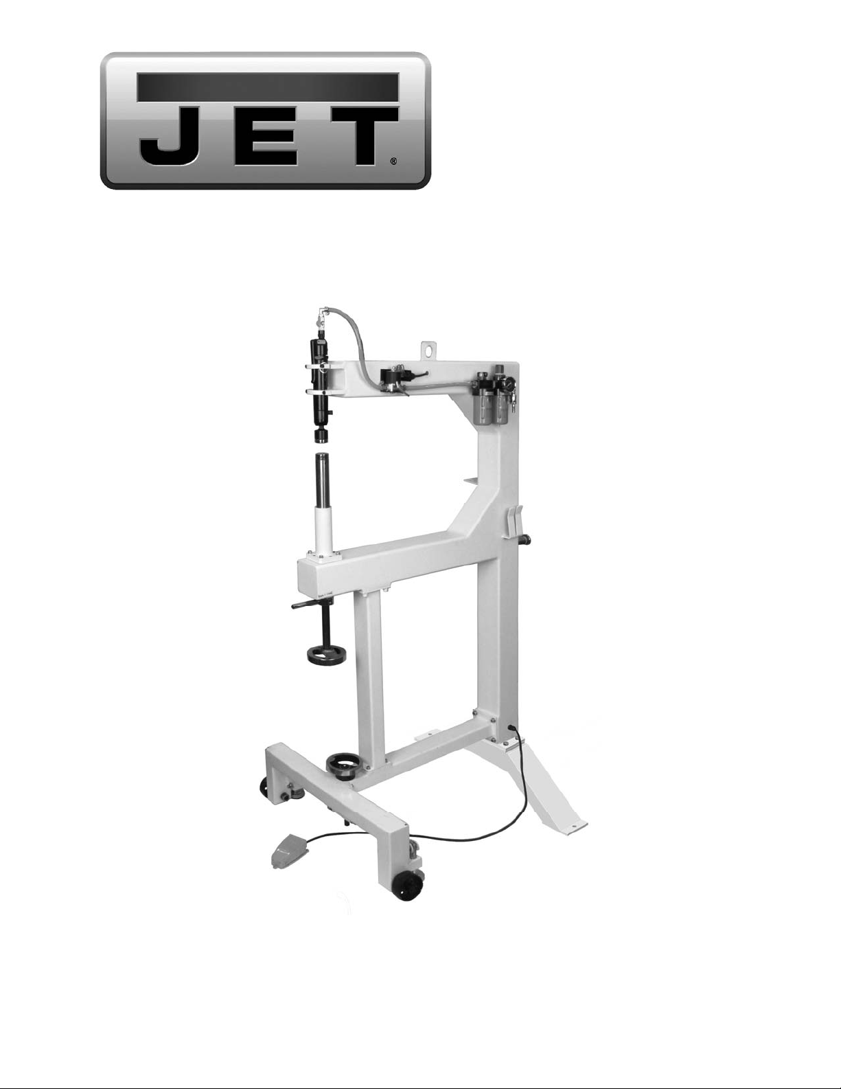
24-inch Pneumatic Planishing Hammer
Model PH-24T
JET
427 New Sanford Road
LaVergne, Tennessee 37086 Part No. M-756121
Ph.: 800-274-6848 Revision A1 05/2014
www.jettools.com Copyright © 2014 JET
Page 2

Warranty and Service
JET® warrant s every pr oduct it sells agai nst ma nufa cturers ’ defects. If on e of our tools needs servic e or repair, pl ease
contact Technical Service by calling 1-800-274-6846, 8AM to 5PM CST, Monday through Friday.
Warranty Period
The general warranty lasts for the time period specified in the literature included with your product or on the official
JET branded website.
• JET products carry a limited warranty which varies in duration based upon the product. (See chart below)
• Accessories carry a limited warranty of one year from the date of receipt.
• Consumable items are defined as expendable parts or accessories expected to become inoperable within a
reasonable amount of use and are covered by a 90 day limited warranty against manufacturer’s defects.
Who is Covered
This warranty covers only the initial purchaser of the product from the date of delivery.
What is Co vered
This warranty covers any defects in workmanship or materials subject to the limitations stated below. This warranty
does not cover failures due directly or indirectly to misuse, abuse, negligence or accidents, normal wear-and-tear,
improper repair, alterations or lack of maintenance.
Warranty Limitations
Woodworking products with a Five Year Warranty that are used for commercial or industrial purposes default to a
Two Year Warranty. Please contact Technical Service at 1-800-274-6846 for further clarification.
How to Get Technical Support
Please contact Technical Service by calling 1-800-274-6846. Please note that you will be asked to provide proof
of initia l p u rch a s e whe n calling. If a product requires further inspection, the Technical Service representative will
explain and assist with any additional action needed. JET has Authorized Service Centers located throughout the
United States. For the name of an Authorized Service Center in your area call 1-800-274-6846 or use the Service
Center Locator on the JET website.
More Information
JET is constantly adding new products. For complete, up-to-date product information, check with your local distributor
or visit the JET website.
How S tate Law A pplies
This warranty gives you specific legal rights, subject to applicable state law.
Limitations on This Warranty
JET LIMITS ALL IMPLIED WARRANTIES TO THE PERIOD OF THE LIMITED WARRANTY FOR EACH PRODUCT.
EXCEPT AS STATED HEREIN, ANY IMPLIED WARRANTIES OF MERCHANTABILITY AND FITNESS FOR A
PARTICULAR PURPOSE ARE EXCLUDED. SOME STATES DO NOT ALLOW LIMITATIONS ON HOW LONG AN
IMPLIED WARRANTY LASTS, SO THE ABOVE LIMITATION MAY NOT APPLY TO YOU.
JET SHALL IN NO EVENT BE LIABLE FOR DEATH, INJURIES TO PERSONS OR PROPERTY, OR FOR
INCIDENTAL, CONTINGENT, SPECIAL, OR CONSEQUENTIAL DAMAGES ARISING FROM THE USE OF OUR
PRODUCTS. SOME STATES DO NOT ALLOW THE EXCLUSION OR LIMITATION OF INCIDENTAL OR
CONSEQUENTIAL DAMAGES, SO THE ABOVE LIMITATION OR EXCLUSION MAY NOT APPLY TO YOU.
JET sells through distributors only. The specifications listed in JET printed materials and on official JET website are
given as general information and are not binding. JET reserves the right to effect at any time, without prior notice,
those alterations to parts, fittings, and accessory equipment which they may deem necessary for any reason
whatsoever. JET
Product Listing with Warranty Period
90 Days – Parts; Consumable items; Light-Duty Air Tools
1 Year – Motors; Machine Accessories; Heavy-Duty Air Tools; Pro-Duty Air Tools
2 Year – Metalworking Machinery; Electric Hoists, Electric Hoist Accessories
5 Year – Woodworking Machinery
Limited Lifetime – JET Parallel clamps; VOLT Series Electric Hoists; Manual Hoists; Manual Hoist
Accessories; Shop Tools; Warehouse & Dock products; Hand Tools
NOTE: JET is a division of JPW Industries, Inc. References in this document to JET also apply to JPW Industries,
Inc., or any of its successors in interest to the JET brand.
®
branded products are not sold in Canada by JPW Industries, Inc.
2
Page 3

Table of Contents
Warranty and Servic e .............................................................................................................................. 2
Table of Contents .................................................................................................................................... 3
Introduction ............................................................................................................................................. 3
Specifications for PH-24T Planishing Hammer ......................................................................................... 6
Features and Terminology ....................................................................................................................... 7
Unpacking, M ounting and Assembly ........................................................................................................ 8
Operation ................................................................................................................................................ 8
Changing Dies ......................................................................................................................................... 9
Maintenance ............................................................................................................................................ 9
Assembly Drawing f or P H-24T Pl anishi ng Hammer ................................................................................ 10
Parts List for PH-24T Planishing Hammer .............................................................................................. 11
Introduction
This manual is provi ded by JET, covering the safe operation and mai ntenance procedures f or the JET
PH-24T Plani shi ng Hammer. This manual cont ains i nstr uc tions on install ation, safety precautions, general
operating proc edures, maintenance i nstructions and part s breakdown. This m achine has been designed
and constructed to pr ovi de years of troubl e free operation if used in accor dance wit h instructi ons set fort h
in this m anual. If there are any questi ons or com ments, please contact either y our local supplier or JET.
JET can also be reached at our web site: www.jettools.com.
3
Page 4

1. Read and understand the ent ire owner’s manual befor e att empting assembly or operati on.
2. Read and understand the warnings po sted on the m achine and i n thi s manual. Fail ure to comply wit h
all of these warnings m ay cause seriou s i njury.
3. Replace the warning labels if they become obscured or remov ed.
4. This planishing hammer is designed and intended for use by properly trained and experienced
personnel only . If you are not familiar with t he proper and safe operati on of a planishing hamm er, do
not use until proper training and knowledge have been obtained.
5. Do not use this planishing hamm er for other than its intended u se. If used f or other purpo ses, JET,
disclaim s any real or i mplied warrant y and h olds itsel f harml ess from any injury t hat may r esult f rom
that use.
6. Always wear approved safety glasses/face shields while using this planishing hammer. Everyday
eyeglasses only have impact resistant lenses; they are not safety glasses.
7. Before operating this planishing hammer, remove tie, rings, watches and other jewelry, and roll
sleeves up past t he elbows. Remove all loose cl othing and confine long hair . Non-slip footwear or
anti-ski d floor strips are recommended.
8. Wear ear protector s (plugs or muffs) during ext ended peri ods of operation.
9. Some dust created by power sanding, sawing, grinding, drilling and other construction activities
contain chemi cals known to cause cancer , bir th defects or other r eproductiv e harm . Some exampl es
of these chemic als are:
• Lead from lead based paint.
• Crystalli ne sil ic a from bricks, cement and other m asonry pr oduc ts.
• Arsenic and chromium from chemically treated lum ber .
Your risk of exposure varies, depending on how often you do this type of work. To reduce your
exposure to these chemicals, work in a well-ventilated area and work with approved safety
equipment, such as face or dust masks that are specifically designed to filter out microscopic
particles.
10. Do not operate this machine while tired or under the influence of dr ugs, alcohol or any medication.
11. M ak e c ertain the machine is properly grounded.
12. M ak e all machine adjustm ents or maintenance with the machine unplugged from the power source.
13. Remove adjusting keys and wrenches. Form a habit of checking to see that keys and adjusting
wrenches are removed from the machine before turning it on. .
14. Check damaged parts. Before further use of the machine, a guard or other part that is damaged
should be carefully checked to determine that it will operate properly and perform its intended
function. Chec k for alignment of moving par ts, binding of moving parts, breakage of parts, mounting
and any other condi ti ons that m ay affect its operati on. A guard or ot her part that i s damaged should
be properly repaired or replaced.
15. P r ov ide for adequate space surrounding work area and non-gl ar e, overhead lighting.
16. K eep the floor around the m achi ne cl ean and free of scrap material, oil and grease.
17. Don' t use in dangerous envi r onm ent. Don't use power tools i n damp or wet l oc ations, or expose them
to rain. Keep work area well lighted.
18. K eep v isitors a safe distanc e from the work area. Keep children away.
19. M ak e y our workshop child proof with padlocks, master switches or by r em ov ing starter keys.
4
Page 5

20. Giv e your work undivi ded attention. Looki ng around, carryi ng on a conversati on and “horse-play” ar e
careless acts that can r esul t in serious injury.
21. Do not overreach. K eep pr oper footi ng and balance at all times.
22. Use the ri ght t ool at the cor rect speed and feed r ate. Do not for ce a tool or attachm ent to do a j ob for
which it was not designed. T he ri ght tool will do the job better and m or e safely.
23. Use recommended accessories; improper accessories may be hazardous.
24. M aintain tools with car e. F ollow instructions for lubr ic ating and changing accessories.
25. Disconnect tools before servicing or changi ng ac c essories.
26. Use l eather gloves when handling sheet metal.
27. K eep hands, fingers and arm s away f r om t he hammer and anvil during operation.
28. Do not exceed the maxim um rated ai r pressure to t he r egulator.
29. Disconnect tool f r om ai r supply when not in use.
30. Turn off the machine before c leaning. Use a brush or compressed air to remove chips or de br is — do
not use your hands.
31. Do not stand on the machine. S eri ous i njur y could occur if the machine tips ov er.
32. Never leave the m ac hine r unning unattended. Turn the power off and do not l eav e the mac hine until it
comes to a complete stop.
33. Remove loose item s and unnecessary work pieces from the area before starting the machine.
Familiariz e you rself with the following safety no ti ces used in this manual:
This means that if precautions are not heeded, it may result in minor injury and/or
possible machine damage.
This means that if precauti ons are not heeded, it may result in serious injury or possibly
even death.
5
Page 6

Specifications for PH-24T Planishing Hammer
Model .......................................................................................................................................................... PH-24T
Stock Number ............................................................................................................................................. 756121
Electrical Power:
Incoming Power ....................................................................................................... 110V, Single-Phase, 60Hz
Controls .................................................................................................................................... foot pedal, 110V
Power Plug included .................................................................................................................................... yes
Power Cable.................................................................................................................................. 16AWG, 9 ft.
Foot Pedal Cable Length ....................................................................................................................... 3-1/2 ft.
General Dimensions:
Throat ........................................................................................................................................................... 24”
Head Opening .......................................................................................................................................... 2-1/2”
Wheels ............................................................................................................................. 3-1/4” Dia. x 1-1/4” W
Hammer Die ........................................................................................................................................... flat Ø2”
Anvil Die ............................................................................................................................................ crown R2”
Anvil shaft insert end diameter ................................................................................................................. 0.079”
Operation:
Workpiece Maximum Gauge (mild sheet steel) ....................................................................................... 16 ga.
Workpiece Maximum Thickness (aluminum, copper) .................................................................................. 1/8”
Air Intake Connector ............................................................................................................................ 1/4” NPT
Air Regulator .......................................................................................................... 3-position (3 speed ranges)
Blows per Minute..................................................................................... 4400-4600 / 3200-3500 / 1800-2000
Maximum Pounds per Hit ............................................................................................................................... 45
Air Pressure Required ....................................................................................... 90-120 PSI (6.33-8.47 kg/cm2)
Air Consumption.................................................................................................................................. 8.8 CFM
Noise Level ............................................................................................................................ 92.26 to 104.3 dB
Lubrication required ........................................................................................ Lubricator cup, ISO32/SAE10W
Construction:
Frame ............................................................................................. welded and gusseted – 0.137” steel tubing
Frame Tube size ...................................................................................................................................... 4” x 4”
Support Tube size .................................................................................................................................... 3” x 2”
Handwheels ........................................................................................................................... polish ed cast iron
Other:
Shipping Weight .....................................................................................................................................250 lbs.
Net Weight ............................................................................................................................................ 220 lbs.
Overall Dimensions, shipping........................................................................ 36-1/4” L x 14-3/5” W x 67-3/4” H
Overall Dimensions, fully assembled ............................................................................... 34” L x 29” W x 66” H
The specifications in this manual are given as general information and are not binding. The above
specifications were current at the time this manual was published, but because of our policy of continuous
improvement, JET reserves the right to effect, at any ti me and without prior notice, changes or alterations to
parts, fittings, and accessory equipment deemed necessary for any reason whatsoever.
Read and understand the entire contents of this manual before attempting
assembly or operat io n! Failure to comply may cause serious inju ry!
6
Page 7

Features and Terminology
Figure 1 - Features
7
Page 8

Unpacking, Mounting and Assembly
Operation
1. With the help of an assistant, carefully
uncrate the planishing hammer. A tab is
welded to the top t ube if you choose to use
a hoist to set up the machine.
2. Determine the most suitable location for
your planishing hammer based on the
planned usage of the machine. Larger
workpieces require a larger space around
the planishing hammer.
3. Mount any loose it ems to the frame, such as
the die tray s, using t he photo on page 7 and
the breakdown on page 10 as guides.
4. Lower the foot pads to contact the flo or , us ing
the handwheel.
5. Secure the planishing hammer to the floor
using fasteners (not included) appropriate for
the floor type. These are inserted through the
holes on the frame’s back leg.
Referring to Fi gur e 2:
6. Attach the pneumatic hammer to the frame
with the upper clamp (has rounded notch)
and lower clamp. Secure the clamps with
four M6x 25 socket head cap s crew s and M6
lock washers.
Keep hands clear of hammer
and anvil area at all ti mes! Failure to comply
may cause serious injury!
Referring to Fi gur e 3:
1. Connect the air compressor to the quick
connector.
2. Set the desired air pressure bet ween 90- 120
PSI using the pressure dial on the
filter/regulator (clockwise to increase). Lock
the setting by pushing down the pressure
dial. Pull up on the di al to readjust a setti ng.
Note: A lower air pressure will provide a
softer hammer blow. Do not exceed 120
psi air pressure.
3. Adj ust the oil fl ow using the di al at the top of
the lubricator. A setti ng of 2 drips per minute
is sufficient for regular operation.
Referring to Fi gur e 3:
7. Check the oi l level in t he lubricator. If the oil
level is low, refill. Refer to Maintenance
section for instructions.
8. Install a male 1/4" quick connector fitting
onto the air inl et of the planishing hammer.
Figure 3
Referring to Fi gur e 4:
4. Adjust the anvil height with the handwheel,
and secure the anv il in posit ion by snugging
the lock collar against the frame.
5. The lock handle can be inserted i nto any of
the threaded holes in the collar, and
tightened usi ng a wrench on t he flats.
Figure 2
8
Page 9

To remove the entire driver from the hammer
barrel, push the t ab on the air hammer housing
and pull down on the driver. To reinstall the
hammer drive, orient the notch toward the
general direction of the tab, and push driver
upward while still pushing back on the tab.
When the driv er is properl y insert ed, the tab will
snap back into pl ac e.
Make sure dri ver and dies are
properly insert e d be for e ope r ating ma c hi ne .
Figure 4
6. Plug the planishing ham mer into the power
supply.
7. With the workpiece between the hammer
and anvil (Figure 5) , press the foot switc h to
begin plani shing.
Note: Planishing blows-per-minute can be adjusted
by turning adjustment knob (see Figure 2).
Figure 6
Maintenance
Figure 5
Changing Dies
Referring to Fi gur e 6:
The PH-24T i s shipped with one cro wned anv il
(or lower) die, and one flat hammer (or upper)
die, which is alr eady installed in the driver.
To remove an anvil die, loosen the set screw
and pull straight up on the anvil die. Install a new
anvil die and tighten set screw. The anvil post
accepts dies with a standard 0. 79” insert end.
To remove a hammer die from the driver, use a
tool to separat e them . When the di e is rem ov ed,
check the condition of the o-ring inside the
driver. To reinstall a hammer die, insert it into
the driver and raise the anvil post up until it
contacts and pushes the di e in.
Check the following before every use:
Oil level in the lubricator; refill as needed
with ISO 32/SAE 10W non-detergent, nonadditive oil. Remove oil plug with a
screwdriver to fill.
All mounting and component hardware and
fasteners; adjust/tighten as necessary.
All air connections; replace leaking or
defective connections.
Worn or shorted wiring; replace as
necessary.
Periodically check the filter/regulator bowl for
fluids or sedi ment accumulati on, and empty it if
needed. To remove a bowl, shut off air supply
and bleed excess air; t hen press the tab, rotate
bowl to the left, and pull down. Reverse
procedure to reinstall bowl. Make sure bowl is
locked in position before applying air to the
system!
9
Page 10

Assembly Drawing for PH-24T Planishing Hammer
10
Page 11

Ordering Replacement Parts
To order parts or reach our service department, call 1-800-274-6848 Monday through Friday (see our
website for business hours, www.jettools.com). Having the Model Number and Serial Number of your
machine available when you call will allow us to serv e you quickl y and ac c ur ately.
Parts List for PH-24T Planishing Hammer
Index No. Part No. Description Size Qty
1 ..................... PH24T-1 .................. Fra me ............................................................................................. 1
1-1.................. PH24T-1-1 ............... Frame Back Leg .............................................................................. 1
2 ..................... PH24T-2 .................. Whee l Leg ....................................................................................... 1
3 ..................... PH24T-3 .................. Cross Leg ....................................................................................... 1
4 ..................... PH24-4 .................... Support Leg .................................................................................... 1
5 ..................... PH24-5 .................... Upper Air Hammer Clamp ............................................................... 1
6 ..................... PH24-6 .................... Lower Air Hammer Clamp ............................................................... 1
9 ..................... PH24-9 .................... Lead Screw Housing ....................................................................... 1
10 ................... PH24-10 .................. Lead Screw ..................................................................................... 1
11 ................... TS-1523021 ............. Socket Set Screw .........................................M6x8 .......................... 1
12 ................... PH24-12 .................. Lock Collar ...................................................................................... 1
12-1 ................ PH24-12-1 ............... Lock Collar Handle .......................................................................... 1
13 ................... PH24-13 .................. Air Hammer ..................................................................................... 1
13-01 ......... PH24-13-01 ............. Back Head ...................................................................................... 1
13-02 ......... PH24-13-02 ............. O-Ring .........................................................3.2x1.9 mm ................ 1
13-03 ......... PH24-13-03 ............. Throttle Valve .................................................................................. 1
13-03- 1 ...... PH24-1 3-03 -1 .......... O-Ring .........................................................3 .5x1.5 mm ................ 1
13-04 ......... PH24-13-04 ............. Spring ............................................................................................. 1
13-05 ......... PH24-13-05 ............. O-Ring .........................................................7.8x2.4 mm ................ 1
13-06 ......... PH24-13-06 ............. Valve Cap ....................................................................................... 1
13-07 ......... PH24-13-07 ............. Lever ............................................................................................... 1
13-08 ......... PH24-13-08 ............. Spring Pin ....................................................Ø5x22.5 mm ............... 1
13-09 ......... PH24-13-09 ............. Hose Adapter .................................................................................. 1
13-10 ......... PH24-13-10 ............. Lock Ring ........................................................................................ 1
13-11 ......... PH24-13-11 ............. Alignment Shim ............................................................................... 2
13-12 ......... PH24-13-12 ............. Rear Valve Block ............................................................................. 1
13-13 ......... PH24-13-13 ............. Pin .................................................................................................. 2
13-14 ......... PH24-13-14 ............. Valve ............................................................................................... 1
13-15 ......... PH24-13-15 ............. Front Valve Block ............................................................................ 1
13-16 ......... PH24-13-16 ............. Piston .............................................................................................. 1
13-17 ......... PH24-13-17 ............. Barrel Sleeve .................................................................................. 1
13-18 ......... PH24-13-18 ............. Nose ............................................................................................... 1
13-19 ......... PH24-13-19 ............. Flat Key........................................................................................... 1
13-20 ......... PH24-13-20 ............. Barrel .............................................................................................. 1
13-21 ......... PH24-13-21 ............. Driver Retainer ................................................................................ 1
13-22 ......... PH24-13-22 ............. Retainer Buffer ................................................................................ 1
13-23 ......... PH24-13-23 ............. Retainer Cap ................................................................................... 1
13-24 ......... PH24-13-24 ............. Hammer Driver ................................................................................ 1
13-25 ......... PH24-13-25 ............. O-Ring .........................................................20x3 mm .................... 1
13-26 ......... PH24T-13-26 ........... Hammer Die .................................................................................... 1
13-27 ......... PH24-13-27 ............. Regulator .....................................................G3/8” .......................... 1
13-28 ......... PH24-13-28 ............. O
14 ................... PH24-14 .................. Solenoid Valve Mount...................................................................... 1
15 ................... PH24-15 .................. Cover Plate ..................................................................................... 1
16 ................... PH24-16 .................. Strain Relief .................................................M16x1.5 ..................... 3
17 ................... PH24-17 .................. Foot Control Switch Cord..............................1.25x3C ...................... 1
18 ................... PH24-18 .................. Solenoid Valve Cord .....................................1.25x3C ...................... 1
19 ................... PH24-19 .................. Power Cord ..................................................................................... 1
20 ................... PH24-20 .................. Pipe Nipple Air Fi tting ...................................1/4" ............................ 1
21 ................... PH24-21 .................. Elbow Air Fitting ...........................................1/4”............................. 1
pen End Wrench ........................................26 mm ........................ 1
11
Page 12

Index No. Part No. Description Size Qty
22 ................... PH24-22 .................. Elbow Air Fitting ...........................................1/4" ............................ 1
23 ................... PH24-23 .................. Air Fitting Connector .....................................1/4" ............................ 5
24 ................... PH24-24 .................. Hose Clamp .................................................Ø10-16 mm ................ 6
25 ................... PH24-25 .................. Air Hose .......................................................PVC Ø12x8 mm ......... 1
26 ................... PH24-26 .................. Foot Control .................................................................................... 1
27 ................... PH24-27 .................. Cable Protector ............................................Ø16 ............................ 1
28 ................... PH24-28 .................. Solenoid Valve ................................................................................ 1
29 ................... PH24-29 .................. Air Filter-Regulator-Lubricator.......................................................... 1
30 ................... PH24-30 .................. Handwheel ...................................................................................... 1
30-1 ................ PH24-30-1 ............... Flat Key........................................................4x16 mm .................... 2
31 ................... TS-1503081 ............. Socket Head Cap Scr ew ..............................M6x35 ...................... 16
32 ................... TS-1503051 ............. Socket Head Cap Scr ew ..............................M6x20 ........................ 6
33 ................... TS-1503071 ............. Socket Head Cap Scr ew ..............................M6x30 ...................... 10
34 ................... TS-1534052 ............. Phillips Pan Head Machine Screw ................M6x15 ........................ 2
35 ................... TS-1540031 ............. Hex Nut ........................................................M5 .............................. 1
36 ................... TS-2361061 ............. Lock Wash e r ................................................Ø6 mm ..................... 32
37 ................... TS-1533052 ............. Phillips Pan Head Machine Screw ................M5x15 ........................ 2
38 ................... 708315-128 .............. External Tooth Lock Washer ........................Ø5 mm ....................... 1
39 ................... TS-1533042 ............. Phillips Pan Head Machine Screw ................M5x12 ........................ 1
40 ................... PH24-40 .................. Die Tray .......................................................................................... 2
41 ................... PH24-41 .................. Wheel Shaft ................................................................. ................... 2
42 ................... PH24-42 .................. Wheel ............................................................................................. 2
43 ................... TS-1503021 ............. Socket Head Cap Scr ew ..............................M6x10 ........................ 2
44 ................... PH24-44 .................. Quick Connect Coupler ................................1/4" ............................ 1
45 ................... PH24T-45 ................ Hex Wrench .................................................6 mm .......................... 1
46 ................... TS-1550030 ............. Fla t Washe r..................................................Ø5 mm ....................... 2
47 ................... TS-155010 ............... Flat Washer..................................................Ø16 mm ..................... 4
48 ................... TS-154010 ............... Hex Nut ........................................................M16 ............................ 4
50 ................... PH24-50 .................. Washer ........................................................................................... 2
51 ................... TS-1550031 ............. Fla t Washe r..................................................Ø5 mm ....................... 2
53 ................... PH24-53 .................. Pressure Gauge ...........................................0-140 psi
.................... 1
54 ................... PH24-54 .................. Lower Anvil ..................................................................................... 1
55 ................... TS-1524041 ............. Socket Set Screw .........................................M8x15 ........................ 4
56 ................... PH24T-56 ................ Hinge Lever..................................................................................... 2
57 ................... PH24T-57 ................ Lead Sc r ew ..................................................................................... 1
58 ................... PH24T-58 ................ Lead Sc r ew Seat ............................................................................. 1
59 ................... PH24T-59 ................ Shaft ............................................................................................... 2
60 ................... PH24T-60 ................ Block ............................................................................................... 2
61 ................... PH24T-61 ................ Pad ................................................................................................. 2
62 ................... PH24T-62 ................ Short Pin ........................................................................................ 2
63 ................... PH24T-63 ................ Long Pin .......................................................................................... 2
64 ................... PH 24T-64 ................ Position ing Collar ............................................................................ 1
65 ................... PH24T-65 ................ Bearing Seat ................................................................................... 1
66 ................... PH 24T-66 ................ Pin .................................................................................................. 2
67 ................... PH 24T-67 ................ Cotter Pin .....................................................Ø2.5 mm .................... 4
68 ................... PH24T-68 ................ Handle ............................................................................................ 1
69 ................... PH 24T-69 ................ O-Ring .........................................................3.1x26 mm ................. 1
70 ................... PH24T-70 ................ Handle Cover .................................................................................. 1
71 ................... PH24T-71 ................ Rolling Handle ................................................................................. 1
72 ................... PH24T-72 ................ Thrust Bearing..............................................Ø15xØ32x12 .............. 1
73 ................... PH24T-73 ................ Cover Pla te for Switch ..................................................................... 1
74 ................... TS-2284082 ............. Phillips Pan Head Machine Screw ................M4x8 .......................... 2
75 ................... TS-1491041 ............. Hex Cap Screw ............................................M10 x30 ...................... 4
76 ................... TS-2361101 ............. Lock Washer ................................................Ø10mm ...................... 4
77 ................... TS-1550071 ............. Flat Washer..................................................Ø10mm ...................... 4
Note: Some parts are shown for illustration purposes only and may not be available individually as replacement parts.
Fasteners with part numbers beginning with TS-, are standard sizes and can usually be found at local hardware
stores.
12
 Loading...