

Page 1
This .pdf document is bookmarked
Operating Instructions and Parts Manual
20-Ga. Pittsburgh Lockformer
Model LF-20
JET
427 New Sanford Road
LaVergne, Tennessee 37086 Part No. M-756090
Ph.: 800-274-6848 Edition 1 09/2016
www.jettools.com Copyright © 2016 JET
Page 2

12. Make certain switch is in OFF position before
connecting the machine to the power supply.
13. Make certain the machine is properly grounded.
1.0 IMPORTANT SAFETY
INSTRUCTIONS
WARNING – To reduce risk of injury:
1. Read and understand the entire owner's
manual before attempting assembly or
operation.
2. Read and understand the warnings posted on
the machine and in this manual. Failure to
comply with all of these warnings may cause
serious injury.
3. Replace warning labels if they become
obscured or removed.
4. This lockformer is designed and intended for
use by properly trained and experienced
perso nnel on ly. If you are no t fam iliar w ith the
proper and safe operation of a lockformer, do
not use until proper training and knowledge
have been obtained.
5. Do not use this machine for other than its
intended use. If used for other purposes, JET
disclaims any real or implied warranty and holds
itself harm less from any inj ury t hat m ay res ult
from that use.
6. Always wear ANSI Z87.1 approved safety
glasses or face sh iel d whil e usin g th is machin e.
(Everyday eyeglasses only have impact
resistant lenses; they are not safety glasses.)
7. Before operating this machine, remove tie,
rings, watches and other jewelry, and roll
sleeves up past the elbows. Do not wear loose
clothing. Confine long hair. Non-slip footwear or
anti-skid floor strips are recom mended. Do not
wear gloves.
8. Wear hearing protection (plugs or muffs) if
noise exceeds safe levels.
9. CALIFORNIA PROPOSITION 65 WARNING:
This product contains chemicals know n to the
State of California to cause cancer, or birth
defects or other reproductive harm.
10. This product, when used for welding, cutting, or
working with metal, produces fumes, gases, or
dusts which contain chemicals known to the
State of California to cause birth defects and, in
some cases, cancer. (California Health and
Safety Code Section 25249.5 et seq.)
11. Do not operate this machine while tired or under
the influence of drugs, alcohol or any
medication.
14. Make all machine adjustments or maintenance
with the machine unplugged from the power
source.
15. Remove adjusting keys and wrenches. Form a
habit of checking to see that keys and adjusting
wrenches are removed from the machine
before turning it on.
16. Keep safety guards in place at all times when
the machine is in use. If removed for
maintenance purposes, use extreme caution
and replace the guards immediately after
completion of maintenance.
17. Check damaged parts. Before further use of the
machine, a guard or other part that is damaged
should be carefully checked to determine that it
will operate properly a nd perform its i ntended
function. Check for alignment of moving parts,
binding of moving parts, breakage of parts,
mounting and any other conditions that may
affect its operation. A guard or other part that is
damaged should be properly repaired or
replaced.
18. Provide for adequate space surrounding work
area and non-glare, overhead lighting.
19. Keep the floor around the machine clean and
free of scrap material, oil and grease.
20. Keep visitors a safe distance from the work
area. Keep children away.
21. Make your workshop child proof w ith padlocks,
master switches or by removing starter keys.
22. Give your work undivided attention. Looking
around, carrying on a conversation and “horseplay” are careless acts that can result in serious
injury.
23. Maintain a balanced stance at all times so that
you do not fall onto moving parts. Do not
overreach or use excessive force to perform
any machine operation.
24. Use the right tool at the correct speed and feed
rate. Do not force a tool or attachment to do a
job for which it was not designed. The right tool
will do the job better and more safely.
25. Use recommended accessories; improper
accessories may be hazardous.
26. Maintain tools with care. Follow instructions for
lubricating and changing accessories.
27. Turn off the machine before cleaning. Use a
brush to remove chips or debris — do not use
bare hands.
2
Page 3

28. Do not stand on the machine. Serious injury
could occur if the machine tips over.
29. Never leave the machine running unattended.
Turn the power off and do not leave the
machine until it comes to a complete stop.
30. Remove loose items and unnecessary work
pieces from the area before starting the
machine.
31. Disconnect machine from power source
(unplug) before changing out roll sets.
32. Top covers must be properly installed before
feeding workpiece.
Familiarize yourself with the following safety notices used in this manual:
This means that if preca utions are not heeded, it m ay result in minor injury a nd/or possible
machine damage.
This means that if precautions are not heeded, it may result in serious, or possibly even fatal,
injury.
33. Don’t use in dangerous environment. Don’t use
power tools in damp or wet location, or expose
them to rain. Keep work area well lighted.
34. Use proper extension cord. Make sure your
extension cord is in good condition. When using
an extension cord, be sure to use one heavy
enough to carry the current your product will
draw. An undersized cord will cause a drop in
line voltage resulting in loss of power and
overheating. Table 1 (sect. 6.2) shows correct
size to use depending on cord length and
nameplate ampere rating. If in doubt, use the
next heavier gage. The smaller the gage
number, the heavier the cord.
2.0 About this manual
This manual is provided by JET, covering the safe operation and maintenance procedures for a JET Model LF20 Lockformer. This manual contains instructions on installation, safety precautions, general operating
procedures, maintenance instructions and parts breakdown. Your machine has been designed and constructed
to provide consistent, long-term operation if used in accordance with the instructions as s et forth in this document.
If there are questions or comments, please contact your local supplier or JET. JET can also be reached at our
web site: www.jettools.com.
Retain this manual for future reference. If the machine transfers ownership, the manual should accompany it.
Read and understand the entire contents of this manual before attempting assembly or
operation! Failure to comply may cause serious injury!
Register your product online -
http://www.jettools.com/us/en /ser vice-and-support/warranty/registration/
3
Page 4

3.0 Table of contents
Section Page
1.0 IMPORTANT SAFETY INSTRUCTI ONS ....................................................................................................... 2
2.0 About this manual .......................................................................................................................................... 3
3.0 Table of contents ............................................................................................................................................ 4
4.0 Specifications ................................................................................................................................................. 5
5.0 Setup and assembly ....................................................................................................................................... 6
5.1 Shipping contents ....................................................................................................................................... 6
6.0 Electrical connections .................................................................................................................................... 6
6.1 GROUNDING INSTRUCTIONS ................................................................................................................. 6
6.2 Extension cords .......................................................................................................................................... 7
7.0 Operation ....................................................................................................................................................... 7
7.1 Pittsburgh Lock Seam procedure ............................................................................................................... 7
7.2 Double Seam procedure ............................................................................................................................ 8
7.3 Drive Cleat procedure ................................................................................................................................ 8
8.0 Adjustments ................................................................................................................................................... 9
8.1 Hold-downs ................................................................................................................................................ 9
9.0 User-maintenance .......................................................................................................................................... 9
9.1 Cleaning and lubrication ............................................................................................................................. 9
9.2 Additional servicing .................................................................................................................................... 9
10.0 Replacement Parts ....................................................................................................................................... 9
10.1.1 LF-20 Lockformer – Exploded View .................................................................................................... 10
10.1.2 LF-20 Lockformer – Parts List ............................................................................................................. 11
10.2.1 LF-20 Upper Bracket – Exploded View ............................................................................................... 12
10.2.2 LF-20 Upper Bracket – Parts List ........................................................................................................ 13
10.3.1 LF-20 Lower Bracket – Exploded View ............................................................................................... 14
10.3.2 LF-20 Lower Bracket – Parts List ........................................................................................................ 15
10.4.1 LF-20 Optional Rollers – Exploded View ............................................................................................. 16
10.4.2 LF-20 Optional Rollers – Parts List ..................................................................................................... 16
11.0 Electrical Connections for LF-20 ................................................................................................................ 17
12.0 Warranty and service ................................................................................................................................. 18
The specifications in this manual were current at time of publication, but because of our policy of continuous
improvement, JET reserves the right to change specifications at any time and without prior notice, without
incurring obligations.
4
Page 5
4.0 Specifications
Model number ............................................................................................................................................... LF-20
Stock number .............................................................................................................................................. 756090
Motor and electricals:
Motor type ............................................................................................................................. TEFC, capacitor start
Horsepower .............................................................................................................................................. 1.5HP
Phase ........................................................................................................................................................ single
Voltage ...................................................................................................................................................... 115 V
Cycle .......................................................................................................................................................... 60Hz
Listed FLA (full load amps) ......................................................................................................................... 14 A
Running amps (no load) ............................................................................................................................. 7.1 A
Starting amps .............................................................................................................................................. 51 A
Start capacitor .......................................................................................................................... 200MF 125VAC
Run capacitor .............................................................................................................................. 40μF 250VAC
Power transfer ........................................................................................................................................... V-belt
On/off switch .................................................................................................... mushroom style with safety key
Power cord ........................................................................................................ SJT 3/14AWG; 6 ft. (1830 mm)
Power plug installed ...................................................................................................................... NEMA 5-15P
Recommended circuit and fuse/breaker size 1 ............................................................................................. 15A
Capacities:
Pittsburgh lock dimensions ........................................ Approx. 25mm (1-in.) of material, 0.5-1.0mm (20-26ga.)
8mm (5/16 in.) width of hammer-over edge, adjustable up to 9.5mm (3/8 in.)
Speed ..................................................................................................................................... 7.62m (25 ft.)/min
Minimum length of workpiece....................................................................................................... 7 in. (178mm)
Main materials:
Cabinet ....................................................................................................................................................... steel
Rolls ................................................................................................................................... hardened alloy steel
Guide fences .............................................................................................................................. hardened steel
Shafts ................................................................................... hardened and ground steel, with needle bearings
Dimensions:
Height table from floor ......................................................................................................... 819 mm (32-1/4 in.)
Overall dimensions (LxWxH) ..................................................... 914 x 419 x 927 mm (36 x 16-1/2 x 36-1/2 in.)
Shipping dimensions (LxWxH) .......................................... 1075 x 510 x 1075 mm (42-5/16 x 20 x 42-5/16 in.)
Weights:
Net.......................................................................................................................................... 266 lb. (120.6 kg)
Shipping ................................................................................................................................. 341 lb. (154.6 kg)
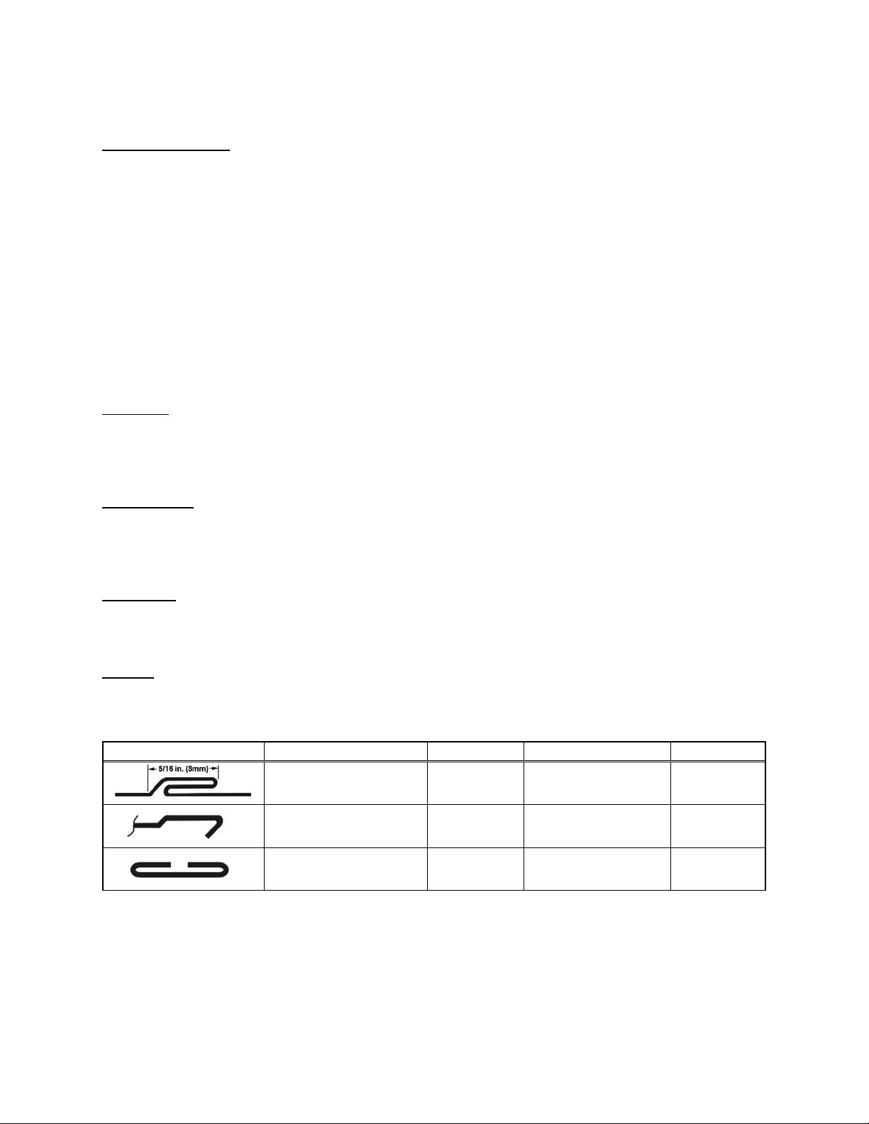
Type Roll set Capacity Approx. mat’l used Size
Pittsburgh lock seam
(standard, pre-mounted)
Double seam (DSS)
OPTIONAL 2
1
Subject to local and national electrical codes.
2
Optional Double Seam and Drive Cleat roll sets are available from JET. See sect. 10.4.1.
Drive cleat (DCS)
OPTIONAL
2
0.5 - 1.0 mm
20 to 26 ga
0.5 - 1.0 mm
20 to 26 ga.
0.5 – 1.0 mm
20 to 26 ga.
25mm (1”)
25.4mm (1”)
54mm (2-1/8”)
8 mm
5/16” width
10 mm
3/8” seam
28.5 mm
1-1/8” width
5
Page 6
Read and understand the entire
contents of this manual before attem pting setup or operation! Failure to comply may cause
serious injury.
installed and grounded in accordance with all local
codes and ordinances.
Do not modify the plug provided - if it will not fit the
outlet, have the proper outlet installed by a qualified
electrician.
5.0 Setup and assembly
Remove all crating and check for shipping damage.
Report any damage immediately to your distributor
and shipping agent. Do not discard any shipping
material until the Lockformer is assembled and
running properly.
Compare contents with the following list to make
sure all parts are intact. Any missing parts should be
reported to your distributor. Read this instruction
manual thoroughly for operation, maintenance and
safety instructions.
Remove fasteners holding machine to pallet, and
use forklift or hoist with straps to move lockformer to
position. Location should be well-lighted, with a
sturdy, level floor. It is recommended that the
machine be secured to the floor with lag screws or
other means for stability.
5.1 Shipping contents
1 Lockformer
2 Wrenches, 23/26 and 12/14mm
2 Hex wrenches, 4mm and 6mm
1 Formed sample plate
10 Double head round keys
6.0 Electrical connections
All electrical connections must
be done by a qualified electrician in compliance
with all local codes and ordinances. Failure to
comply may result in serious injury.
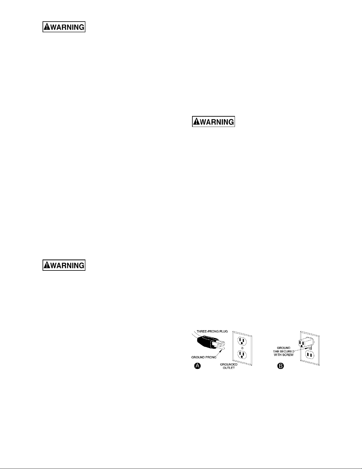
The LF-20 Lockformer is rated at 115-volt power
only, and is supplied with a plug designed for use on
a circuit with a grounded outlet that looks like the
one pictured in Figure 6-1.
Before connecting to power source, be sure switch
is in off position.
Improper connection of the equipment-grounding
conductor can result in a risk of electric shock. The
cond uctor with insulation having an outer surface
that is green with or without yellow stripes is the
equipment-grounding conductor. If repair or
replacement of the electric cord or plug is
necessary, do not connect the equipment-grounding
conductor to a live terminal.
Check with a qualified
electrician or service personnel if the grounding
instructions are not completely understood, or if
in doubt as to whether the tool is properly
grounded. Failure to comply may cause serious
or fatal injury.
Use only 3-wire extension cords that have 3-prong
grounding plugs and 3-pole receptacles that accept
the tool's plug.
Repair or replace damaged or worn cord
immediately.
This machine is for use on a nomi nal 120-V circ uit,
and has a grounded plug that looks like the plug
illustrated in sketch A in Figure 6-1. A temporary
adaptor that looks like the adaptor illustrated in
sketch B may be used to connect this plug to a 2pole receptacle as shown in sketc h B if a properly
grounded outlet is not available. The temporary
adaptor should be used only until a properly
grounded outlet (sketch A) can be installed by a
qualified electrician. The green colored rigid ear,
lug, or the like extending from the adaptor must be
connected to a permanent ground such as a
properly grounded outlet box cover. W henever the
adaptor is used, it must be held in place by a metal
screw.
In Canada, the use of a temporary adapto r is not
permitted by the Canadian Electrical Code, C22.1.
It is recommended that the Lockformer be
connected to a dedicated 15 amp circuit with circuit
breaker or fuse. If connected to a circuit protected
by fuses, use time delay fuse marked “D”. Local
codes take precedence over recommendations.
6.1 GROUNDING INSTRUCTIONS
This machine must be grounded. In the event of a
malfunction or breakdown, grounding provides a
path of least resistance for electric current to reduce
the risk of electric shock. This tool is equipped w it h
an electric cord having an equipment-grounding
conductor and a grounding plug. The plug must be
plugged into a matching outlet that is properly
Figure 6-1
6
Page 7

6.2 Extension cords
The use of extension cords is discouraged; try to
position machines near the power source. If an
extension cord is necessary, make sure it is in good
condition. When using an extension cord, be su re to
use one heavy enough to carry the current your
product will draw. An undersized cord will cause a
drop in line voltage resulting in loss of power and
overheating. Table 1 shows correct size to use
depending on cord length and nameplate ampere
rat ing . If in d o ubt , use t he ne xt hea v ie r g a uge . T he
smaller the gauge number, the heavier the cord.
Extension Cord Recommended Gauges (AWG)
Extension cord length *
25
50
75
100
150
200
Amps
< 5 16 16 16 14 12 12
5 to 8 16 16 14 12 10 NR
8 to 12 14 14 12 10 NR NR
12 to 15 12 12 10 10 NR NR
15 to 20 10 10 10 NR NR NR
21 to 30 10 NR NR NR NR NR
*based on limiting the line voltage drop to 5V at 150% of the rated
amperes. NR = Not Recommen ded.
feet
feet
feet
feet
feet
feet
Table 1
7.0 Operation
The following fig ures show top
cover removed for clarity only. All top covers
must be installed before operating machine.
Failure to comply may cause serious injury.
NOTE: Length of workpiece must be at least 7inches. If a shorter piece is required, process a
longer piece, then cut to length.
1. Make sure workp iece is free of burrs or twist
from snip cuts.
Twists or bent notches in
material can strike and damage the knifeedge roll that holds open the pocket of the
Pittsburgh Lock. Flatte n such edges before
feeding material.
2. Adjust entry fence, using a straight edge. See
Figure 7-2. Entry fence position determines
width of hammer-over edge. Tighten both nuts
on entry fence.
3. Adjust exit fence as follows: Run a test piece
through and stop machine when workpiece h as
reached end of exit table but is still pinched
between the rolls. Move fence into position just
flush or slightly clear of workpiece edge. Exit
fence must not bear pressure against
workpiece under normal circumstances.
Tighten down fence.
4. Hold material against entry fence and slide it
into forming head until machine engages
workpiece and pulls it through. Make sure
workpiece remains against entry fence until its
trailing end is engaged by the rolls.
If a wider or narrower hammer-over edge is desired,
move entry fence to give desired width. Move entry
fence in to produce wider edge, out to produce
narrower edge. Make sure to move both ends of
entry fence the same distance, keeping it parall el to
front edge of machine’s top plate. See Figure 7-2.
7.1 Pittsburgh Lock Seam procedure
This machine comes pre-installed with a Pitt sburgh
lock roll set, and requires only fence adj ustment to
proceed with this operation.
Figure 7-2: Pittsburgh Lock Seam setup
Figure 7-1
7
Page 8

Figure 7-3: Double Seam setup (optional roll set)
Figure 7-4: Drive Cleat setup (optional roll set)
Always disconnect machine
from power before installing roll sets. Failure to
comply may cause serious injury.
7.2 Double Seam procedure
See Figure 7-3.
1. Disconnect machine from power source.
reached end of exit table but is still pinched
between the rolls. Move fence into position just
flush or slightly clear of workpiece edge. Exit
fence must not bear against workpiece. Tighten
down fence.
9. Start machine and feed workpiece.
2. Remove top cover, and rear top plate.
3. Select first pair of rolls marked “T1” and “B1”,
and slide them on the shafts at the left, or entry
side, of machine. Place “T1” on top shaft, B1 on
bottom shaft. Insert key into keyway for each
roll. THE NUMBERED SIDES OF ROLLS
MUST FACE OUTWARD.
4. Repeat procedure with rolls “T2” and “B2”
through “T5” and “B5”, placing them in
sequence from left to right. All rolls marked “T”
should be on top shafts; all rolls marked “B”
should be on bottom shafts.
5. Fasten rolls to shafts with the provided socket
head cap screws and washers.
6. Lay straight edge against outside surface of
rolls, and position entry fence at 1-1/8”
clearance from straight edge, as shown in
Figure 7-3. Tighten dow n both screws on entry
fence.
7. Reinstall rear top plate, and top cover.
8. Adjust exit fence as follows: Run a test piece
through and stop machine when workpiece has
7.3 Drive Cleat procedure
See Figure 7-4.
IMPORTANT: Make sure to cut the material a full 2-
1/8 inch wide to ensure an accurate cleat.
1. Disconnect machine from power source.
2. Follow same procedure as for double seam
rolls, but leave roll “T2” loose. T his roll centers
itself to the bottom roll and should not be fixed
in place with a socket cap screw. However,
double head round keys are used with all the
rolls.
3. Position entry fence so that centerline of
material will ali gn with centerline of rolls. This is
importan t – if i t is not cente red , the cleat will n ot
be accurate. Tighten down fence.
4. Reinstall rear top plate, and top cover.
5. Tighten hold-down stud (see Figure 7-1) so that
“T5” and “B5” rolls do not separate w hen drive
cleat passes through.
8
Page 9

6. Adjust exit fence as follows: Run a test piece
through and stop machine when workpiece has
reached end of exit table but is still pinched
between the rolls. Move fence into position just
flush or slightly clear of workpiece edge. Exit
fence must not bear against workpiece. Tighten
down fence.
7. Start machine and feed workpiece.
8.0 Adjustments
8.1 Hold-downs
material starts working away from entry
fence, tighten hold-down bolt on entry side.
• If material curls up after leaving forming
head, or shows extremely heavy pressure
marks, loosen hold-down bolts (or studs)
slightly.
5. After adjustments, lock setting of the bolts by
tightening side screw (X, Figure 7-1). Lock
setting of studs by tightening top nuts.
9.0 User-maintenance
Refer to Figure 7-1.
Adjustment can be made to accommodate
variations in material thickness and hard ness. T he
hold-down bolts are adjusted for Pittsburgh lock set;
the hold-down studs are adjusted for optional roll
sets. These fasteners set the tension for top and
bottom plates to move, allowing material to slide
between them. Only adjust hold-downs if there is
a problem feeding the material. If material slips,
tends to leave the guide fence, or curls up at exit,
adjust as follows:
1. Disconnect machine from power source.
2. Remove top cover.
3. Tighten ho ld-down bolt s (or st uds) until snug,
then loosen them a quarter turn. This will
usually give proper adjustment for all material
thicknesses.
4. Reinstall top cover and run a test piece through
machine:
• If material slips, tighten both hold-down
bolts (or studs) equally until problem is
resolved. If it slips as it leaves the rolls,
tighten hold-down bolt on exit side. If
Before doing maintenance on
the machine, disconnect it from the electrical
supply by pulling out the plug or switching off
the main switch. Failure to comply may cause
serious injury.
9.1 Cleaning and lubrication
Insert oil every 4 hours of operation into the six oil
fittings at back of machine. These lubricate the main
bearings. Recommended oil is Mobil DTE Oil
LightTM, or equivalent.
Apply a multi-purpose lithium grease to the drive
gears after approximately 40 hours of operation, or
as needed.
Keep forming rolls and table surface clean and free
of deposits.
9.2 Additional servicing
Any additional servicing should be performed by an
authorized service technician.
10.0 Replacement Parts
Replacement parts are listed on the following pages. To order parts or reach our service department, call 1-800274-6848 Monday through Friday, 8:00 a.m. to 5:00 p.m. CST. Havin g the Model Number and Serial Number of
your machine available when you call will allow us to serve y ou quickly and accurately.
Non-proprietary parts, such as fasteners, can be found at local hardware stores, or may be ordered from JET.
Some parts are shown for reference only, and may not be available individually.
9
Page 10

10.1.1 LF-20 Lockformer – Exploded View
10
Page 11

10.1.2 LF-20 Lockformer – Parts List
Index No Part No Description Size Qty
1 ................ TS-0071151 .............. Hex Cap Screw ........................................................ 5/8-11x6 ........................ 2
2 ................ TS-155010 ................ Flat Washer ............................................................. M16 ............................... 2
3 ................ TS-0207021 .............. Socket HD Cap Screw ............................................. 1/4-20x1/2 ................... 10
4 ................ LF20-104 ................... Spacer .................................................................... ...................................... 2
5 ................ LF20-105 ................... Cover ...................................................................... ...................................... 1
6 ................ VB-B52 ...................... V-Belt ....................................................................... B52................................ 1
7 ................ TS-059303 ................ Cap Nut.................................................................... 3/8-16 ............................ 8
8 ................ TS-0561031 .............. Hex Nut .................................................................... Full 3/8-16 ................... 12
9 ................ TS-0680041 .............. Flat Washer ............................................................. 3/8 ............................... 10
10 .............. LF20-110 ................... Full Threaded Stud ................................................. 3/8"-16UNC*128L ......... 2
11 .............. LF20-111 ................... Oil Pipe .................................................................... 6*400 mm...................... 6
12 .............. LF20-112 ................... Motor Pulley ............................................................. ...................................... 1
13 .............. TS-1523041 .............. Socket Set Screw .................................................... M6x12 ........................... 1
14 .............. 5508945 .................... Double Head Round Key ......................................... 5*5*30L mm .................. 1
15 .............. LF20-115 ................... Motor………………………………… ………….1.5HP/115V/60Hz/4P/1Ph ....... 1
.................. LF20-115SC .............. Starting Capacitor (not shown) ................................ 200MF 125VAC ............ 1
.................. LF20-115RC.............. Running Capacitor (not shown) ............................... 40μF 250VAC ............... 1
.................. LF20-115MF.............. Motor Fan (not shown)............................................. ...................................... 1
.................. LF20-115CS .............. Centrifugal Switch (not shown) ................................ ...................................... 1
.................. LF20-115FC .............. Fan Cover (not shown) ............................................ ...................................... 1
16 .............. LF20-116 ................... Motor Plate .............................................................. ...................................... 2
17 .............. TS-0720091 .............. Lock Washer, Medium ............................................. 3/8 ................................. 8
18 .............. TS-0680041 .............. Flat Washer ............................................................. 3/8 ................................. 8
19 .............. TS-0060061 .............. Hex Cap Screw ........................................................ 3/8-16x1-1/4 .................. 4
20 .............. LF20-120 ................... Guide Fence ............................................................ ...................................... 4
21 .............. LF20-121 ................... Carriage Bolt ............................................................ 3/8-16x1 ...................... 12
22 .............. LF20-122 ................... Cabinet Cover ......................................................... ...................................... 2
23 .............. F010967 .................... Socket HD Flat Screw.............................................. 1/4-20x1/2 ..................... 4
24 .............. LF20-124 ................... Top Plate ................................................................. ...................................... 2
25 .............. F010752 .................... Socket HD Flat Screw.............................................. 3/8-16x1 ........................ 4
26 .............. LF20-126 ................... Soft Pad .................................................................. ...................................... 1
27 .............. LF20-127 ................... Female Thread Fitting.............................................. ∅6xPT 1/8" ................... 6
28 .............. LF20-128 ................... Oil Fitting.................................................................. PT 1/8" .......................... 6
29 .............. LF20-129 ................... Cable Gland ............................................................. PG 13.5 ......................... 2
30 .............. LF20-130 ................... Cabinet .................................................................. ...................................... 1
31 .............. LF20-131 ................... Switch Box ............................................................... ...................................... 1
32 .............. LF20-132 ................... Strain Relief ............................................................ SB8R-3 ......................... 2
33 .............. LF20-133 ................... Power Cord……............................................SA 14AWG/3C/285cm/CSA ..... 1
34 .............. LF20-134 ................... Motor Cord……… ……………………………...SJT 14AWG/3C/95cm ............. 1
35 .............. LF20-135 ................... Switch Assembly...................................................... PJ9501-1A .................... 1
36 .............. LF20-136 ................... Self-Drilling Screw .................................................. M3*16L ......................... 4
37 .............. LF20-137 ................... Wire Connector ........................................................ TM-2.............................. 1
38 .............. LF20-138 ................... JET Knob ................................................................ 1/4-20 ............................ 1
.................. JET-138..................... JET Logo (not shown).............................................. 138x57mm .................... 1
.................. LM000228 ................. ID Label, LF-20 (not shown) .................................... ...................................... 1
.................. LM000223 ................. Warning Label (n ot sh own) ...................................... ...................................... 1
.................. LF20-TP .................... Tool Package (includes items below) ...................... ...................................... 1
.................. .................................. Wrench (not shown) ................................................ 12*14 mm...................... 1
.................. .................................. Wrench (not shown) ................................................ 23*26 mm...................... 1
.................. .................................. Hex Wrench (not shown) ......................................... 4mm ............................. 1
.................. .................................. Hex Wrench (not shown) ......................................... 6mm ............................. 1
.................. .................................. Double Head Round Key (not shown) ..................... 5*5*25L mm ................ 10
11
Page 12

10.2.1 LF-20 Upper Bracket – Exploded View
12
Page 13

10.2.2 LF-20 Upper Bracket – Parts List
Index No Part No Description Size Qty
1 ................ TS-0270011 .............. Socket Set Screw .................................................... 5/16-18x1/4 ................... 1
2 ................ LF20-202 ................... Upper Front Die Clamping Plate .............................. ...................................... 1
3 ................ LF20-203 ................... Die T5 ...................................................................... ...................................... 1
4 ................ LF20-204 ................... Needle Bearing ........................................................ BA1012 ......................... 1
5 ................ LF20-205 ................... Shaft ....................................................................... ...................................... 1
6 ................ LF20-206 ................... Die T6 ...................................................................... ...................................... 1
7 ................ 6293358 .................... Double Head Round Key ......................................... 5*5*25L mm .................. 5
8 ................ LF20-208 ................... Die T4 ...................................................................... ...................................... 1
9 ................ LF20-209 ................... Die T3 ...................................................................... ...................................... 1
10 .............. TS-0070041 .............. Hex Cap Screw ........................................................ 1/2-13x1-3/4 .................. 8
11 .............. TS-0720111 .............. Lock Washer, Medium ............................................. 1/2 ................................. 8
12 .............. LF20-212 ................... Needle Bearing ........................................................ BA1412 ....................... 10
13 .............. LF20-213 ................... Die T2 ...................................................................... ...................................... 1
14 .............. LF20-214 ................... Die T1 ...................................................................... ...................................... 1
15 .............. LF20-215 ................... Connecting Rod ....................................................... ...................................... 2
16 .............. LF20-216 ................... Connecting Rod with Hole ....................................... ...................................... 2
17 .............. LF20-217 ................... Upper Rear Die Clamping Plate .............................. ...................................... 1
18 .............. TS-0680031 .............. Flat Washer ............................................................. 5/16 .............................. 5
19 .............. TS-0208071 .............. Socket HD Cap Screw ............................................. 5/16-18x1-1/4 ............... 5
13
Page 14

10.3.1 LF-20 Lower Bracket – Exploded View
14
Page 15

10.3.2 LF-20 Lower Bracket – Parts List
Index No Part No Description Size Qty
1 ................ TS-0070041 .............. Hex Cap Screw ........................................................ 1/2-13x1-3/4 ................ 11
2 ................ TS-0720111 .............. Lock Washer, Medium ............................................. 1/2" ............................. 11
3 ................ TS-1523051 .............. Socket Set Screw .................................................... M6x 16 ........................... 1
4 ................ LF20-304 ................... Double Head Round Key ......................................... 5*5*25L mm .................. 9
5 ................ LF20-305 ................... Gear Pulley .............................................................. ...................................... 1
6 ................ LF20-306 ................... Gear Shaft ............................................................... ...................................... 1
7 ................ TS-0270011 .............. Socket Set Screw .................................................... 5/16-18x1/4 ................... 5
8 ................ LF20-308 ................... Needle Bearing ........................................................ BA1412 ....................... 13
9 ................ LF20-309 ................... Needle Bearing ........................................................ BA1012 ......................... 1
10 .............. LF20-310 ................... Die B5 ...................................................................... ...................................... 1
11 .............. LF20-311 ................... Shaft ....................................................................... ...................................... 1
12 .............. LF20-312 ................... Connecting Rod ....................................................... ...................................... 2
13 .............. LF20-313 ................... Connecting Rod ....................................................... ...................................... 1
14 .............. LF20-314 ................... Connecting Rod ....................................................... ...................................... 2
15 .............. LF20-315 ................... Bracket..................................................................... ...................................... 1
16 .............. LF20-316 ................... Gear ........................................................................ ...................................... 2
17 .............. LF20-317 ................... Needle Bearing ........................................................ BA1212ZOH.................. 6
18 .............. LF20-318 ................... Copper Adapter ....................................................... ∅6*PT 1/8" .................... 6
19 .............. TS-0211051 .............. Socket HD Cap Screw ............................................. 1/2-13x1 ........................ 1
20 .............. LF20-320 ................... Lower Front Die Clamping Plate .............................. ...................................... 1
21 .............. LF20-321 ................... Spring .................................................................... ...................................... 1
22 .............. LF20-322 ................... Disc ......................................................................... ...................................... 1
23 .............. LF20-323 ................... Pin ........................................................................... ...................................... 1
24 .............. TS-0208061 .............. Socket HD Cap Screw ............................................. 5/16-18x1 ...................... 1
25 .............. TS-0561021 .............. Hex Nut .................................................................... Full 5/16-18 ................... 1
26 .............. LF20-326 ................... Spur Gear ................................................................ ...................................... 3
27 .............. LF20-327 ................... Die B 3 ..................................................................... ...................................... 1
28 .............. LF20-328 ................... Spur Gear ................................................................ ...................................... 1
29 .............. LF20-329 ................... Die Shaft B 3............................................................ ...................................... 1
30 .............. LF20-330 ................... Die B2 ...................................................................... ...................................... 1
31 .............. LF20-331 ................... Connecting Rod ....................................................... ...................................... 1
32 .............. ST W22 ...................... C Ring ..................................................................... STW-22 ........................ 2
33 .............. LF20-333 ................... Needle Bearing ........................................................ BA1416 ......................... 1
34 .............. LF20-334 ................... Collar ....................................................................... ...................................... 2
35 .............. LF20-335 ................... Gear Shaft ............................................................... ...................................... 1
36 .............. LF20-336 ................... Gear Shaft ............................................................... ...................................... 1
37 .............. LF20-337 ................... Die B6 ...................................................................... ...................................... 1
38 .............. LF20-338 ................... Die B4 ...................................................................... ...................................... 1
39 .............. LF20-339 ................... Die B1 ...................................................................... ...................................... 1
40 .............. LF20-340 ................... Lower Rear Die Clamping Plate .............................. ...................................... 1
41 .............. TS-1550071 .............. Flat Washer ............................................................. M10 ............................... 2
42 .............. LF20-342 ................... Pin ........................................................................... ...................................... 2
43 .............. TS-0680031 .............. Flat Washer ............................................................. 5/16 ............................... 5
44 .............. TS-0208071 .............. Socket HD Cap Screw ............................................. 5/16-18x1-1/4 ................ 5
15
Page 16

10.4.1 LF-20 Optional Rollers – Exploded View
10.4.2 LF-20 Optional Rollers – Parts List
Index No Part No Description Size Qty
1 ................ 756092 ...................... Drive Cleat Rolls, set of 10 ...................................... ...................................... 1
2 ................ 756091 ...................... Double Seam Rolls, set of 10 .................................. ...................................... 1
16
Page 17

11.0 Electrical Connections for LF-20
17
Page 18

12.0 Warranty and service
JET warrants ev ery product it sells against manufacturers’ defects. If one of our tools needs ser v i ce or repair, please
contact Technical Service by calling 1-800-274-6846, 8AM to 5PM CST, Monday through Friday.
Warranty Period
The general warranty lasts for the t ime period specified in the literature included with your product or on the official
JET branded website.
• JET products carry a limited warranty which varies in duration based upon the product. (See chart below)
• Accessories carry a limited warranty of one year from the date of receipt.
• Consumable items are defined as expendable parts or accessories expected to become inoperable wi t hin a
reasonable amount of use and ar e covered by a 90 day limited warranty against manufacturer’s defects.
Who is Covered
This warranty covers only the initial purchaser of the product from the date of delivery.
What is Co vered
This warranty covers any defects in workmanship or materials subject to the limitations stated below. This warranty
does not cover failures due directly or indirectly to misuse, abuse, negligence or accidents, normal wear-and-tear,
improper repair, alterations or lack of maintenance. JET woodworking machinery is designed to be used with Wood.
Use o f these machin es in t he process i ng of metal, plastics, or oth er m aterials out side recom mended gui deli nes m ay
void the warranty. The exceptions are acrylics and other natural items that are made specifically for wood turning.
Warranty Limitations
Woodworking products with a Five Year Warranty that are used for commercial or industrial purposes default to a
Two Year Warranty. Please contact Technical Service at 1-800-274-6846 for further clarification.
How to Get Technical Support
Please contact Technical Service by calling 1-800-274-6846. Please note that you will be asked to provide proof
of initia l p u rch a s e whe n calling. If a product requires further inspection, the Technical Service representative will
explain and assist with any additional action needed. JET has Authorized Service Centers located throughout the
United States. For the name of an Authorized Service Center in your area call 1-800-274-6846 or use the Service
Center Locator on t he JET website.
More Information
JET is constantly adding new pr oducts. For complete, up-to-date product information, check wi th your local distributor
or visit the JET website.
How State Law Appli es
This warranty gives you specific legal rights, subject to applicable st ate law.
Limitations on This Warranty
JET LIMITS ALL IMPLIED WARRANTIES TO THE PERIOD OF THE LIMITED WARRANTY FOR EACH PRODUCT.
EXCEPT AS STATED HEREIN, ANY IMPLIED WARRANTIES OF MERCHANTABILITY AND FITNESS FOR A
PARTICULAR PURPOSE ARE EXCLUDED. SOME STATES DO NOT ALLOW LIMITATIONS ON HOW LONG AN
IMPLIED WARRANTY LASTS, SO THE ABOVE LIMITATION MAY NOT APPLY TO YOU.
JET SHALL IN NO EVENT BE LIABLE FOR DEATH, INJURIES TO PERSONS OR PROPERTY, OR FOR
INCIDENTAL, CONTINGENT, SPECIAL, OR CONSEQUENTIAL DAMAGES ARISING FROM THE USE OF OUR
PRODUCTS. SOME STATES DO NOT ALLOW THE EXCLUSION OR LIMITATION OF INCIDENTAL OR
CONSEQUENTIAL DAMAGES, SO THE ABOVE LIMITATION OR EXCLUSION MAY NOT APPLY TO YOU.
JET sells through distributors only. The specifications listed in JET printed materials and on of fi cial JET website are
given as gener al information and ar e not binding. JET reserves the right to effect at any time, without prior notice,
those alterations to parts, fittings, and accessory equipment which they may deem necessary for any reason
whatsoever. JET
Product Listing with Warranty Period
90 Days – Parts; Consumable items
1 Year – Motors; Machine Accessories
2 Year – Met al working Machinery; Electric Hoists, Electric Hoist Accessories; Woodworking Machi nery used
for industrial or commercial purposes
5 Year – Woodworking Machinery
Limited Lifetime – JET Parallel clamps; VOLT Series Electric Hoists; Manual Hoists; Manual Hoist
Accessories; Shop Tools; Warehouse & Dock pr oducts; Hand Tools; Air Tools
NOTE: JET is a division of JPW Industries, Inc. References i n t his document to JET also apply to JPW Industries,
Inc., or any of its successors in interest to the JET brand.
®
branded products are not sol d in Canada by JPW Industries, Inc.
18
Page 19

This page intentionally left blank.
19
Page 20

427 New Sanford Road
LaVergne, Tennessee 37086
Phone: 800-274-6848
www.jettools.com
20
 Loading...