

Page 1
This .pdf document is bookmarked
Operating Instructions and Parts Manual
14ga. x 60in. Electric Plate Roller
Model EPR-1460-3
JET
427 New Sanford Road
LaVergne, Tennessee 37086 Part No. M-756030
Ph.: 800-274-6848 Edition 1 08/2016
www.jettools.com Copyright © 2016 JET
Page 2

1.0 IMPORTANT SAFETY
INSTRUCTIONS
damaged should be properly repaired or
replaced.
13. Make all machine adjustments or maintenance
with machine unplugged from power source.
14. Use the right tool. Do not force a tool or
attachment to do a job that it was not designed
to do.
WARNING – To reduce risk of injury:
1. Read and understand the entire owner’s
manual before attempting assembly or
operation.
2. Read and understand the warnings posted on
the machine and in this manual. Failure to
comply with all of these warnings may cause
serious injury.
3. Replace warning labels if they become
obscured or removed.
4. This electric plate roller is designed and
intended for use by properly trained and
experienced personnel only. If you are not
familiar with the proper and safe operation of a
plate roller, do not use it until proper training and
knowledge have been obtained.
5. Do not use this plate roller for other than its
intended use. If used for other purposes, JET
disclaims any real or implied warranty and holds
itself harmless from any injury that may result
from that use.
6. Always wear ANSI Z87.1 approved safety
glasses or face shield while using this machine.
(Everyday eyeglasses only have impact
resistant lenses; they are not safety glasses.)
7. Wear ear protectors (plugs or muffs) if noise
exceeds safe levels.
8. Make certain the machine is properly grounded.
15. Make certain the switch is in the OFF position
before connecting the machine to the power
supply.
16. Remove adjusting keys and wrenches. Form a
habit of checking to see that keys and adjusting
wrenches are removed from the machine
before turning it on.
17. Give your work undivided attention. Looking
around, carrying on a conversation and "horseplay" are careless acts that can result in serious
injury.
18. Keep visitors a safe distance from the work
area. Keep children away.
19. Make your workshop child proof with padlocks,
master switches or by removing starter keys.
20. Do not overreach. Failure to maintain proper
working position can cause you to fall into the
machine or allow clothing to get caught, pulling
you into the machine.
21. Keep the floor around the machine clean and
free of scrap material, oil and grease.
22. Use recommended accessories; improper
accessories may be hazardous.
23. Some dust created by power sanding, sawing,
grinding, drilling and other construction
activities contain chemicals known to cause
cancer, birth defects or other reproductive
harm. Some examples of these chemicals are:
9. Before operating the machine, remove tie,
rings, watches, other jewelry, and roll sleeves
up past the elbows. Remove all loose clothing
and confine long hair.
10. Keep the floor around the machine clean and
free of scrap material, oil and grease.
11. Keep machine guards in place at all times when
the machine is in use. If removed for
maintenance purposes, use extreme caution
and replace the guards immediately upon
completion of maintenance.
12. Check damaged parts. Before further use of the
machine, a guard or other part that is damaged
should be carefully checked to determine that it
will operate properly and perform its intended
function. Check for alignment of moving parts,
binding of moving parts, breakage of parts,
mounting and any other conditions that may
affect its operation. A guard or other part that is
2
• Lead from lead based paint.
• Crystalline silica from bricks, cement and
other masonry products.
• Arsenic and chromium from chemically
treated lumber.
Your risk of exposure varies, depending on how
often you do this type of work. To reduce your
exposure to these chemicals, work in a wellventilated area and work with approved safety
equipment, such as face or dust masks that are
specifically designed to filter out microscopic
particles.
24. Do not operate this machine while under the
influence of drugs, alcohol or any medication.
25. Keep tools sharp and clean for safe and best
performance.
26. Deburr any sharp metal edges of the workpiece
before placing it into the machine.
Page 3

27. Keep hands away from the moving rolls.
33. The plate roller should be anchored to the floor.
28. Provide for adequate space surrounding work
area and non-glare, overhead lighting.
29. Don't use in dangerous environment. Don't use
power tools in damp or wet locations, or expose
them to rain.
30. Do not stand on the machine. Serious injury
could occur if the machine tips over.
31. Never leave the machine running unattended.
Turn the power off and do not leave the
machine until it comes to a complete stop.
32. Use only JET factory authorized replacement
parts and accessories; otherwise, the warranty
and guarantee are null and void.
Familiarize yourself with the following safety notices used in this manual:
This means that if precautions are not heeded, it may result in minor injury and/or possible
machine damage.
This means that if precautions are not heeded, it may result in serious, or possibly even fatal,
injury.
34. Use proper extension cord. Make sure your
extension cord is in good condition. When using
an extension cord, be sure to use one heavy
enough to carry the current your product will
draw. An undersized cord will cause a drop in
line voltage resulting in loss of power and
overheating. Table 1 (sect. 8.3) shows correct
size to use depending on cord length and
nameplate ampere rating. If in doubt, use the
next heavier gage. The smaller the gage
number, the heavier the cord.
SAVE THESE INSTRUCTIONS
2.0 About this manual
This manual is provided by JET, covering the safe operation and maintenance procedures for a JET Model EPR1460 Electric Plate Roller. This manual contains instructions on installation, safety precautions, general operating
procedures, maintenance instructions and parts breakdown. Your machine has been designed and constructed
to provide consistent, long-term operation if used in accordance with the instructions as set forth in this document.
If there are questions or comments, please contact your local supplier or JET. JET can also be reached at our
web site: www.jettools.com.
Retain this manual for future reference. If the machine transfers ownership, the manual should accompany it.
Read and understand the entire contents of this manual before attempting assembly or
operation! Failure to comply may cause serious injury!
Register your product online -
http://www.jettools.com/us/en/service-and-support/warranty/registration/
3
Page 4

3.0 Table of contents
Section Page
1.0 IMPORTANT SAFETY INSTRUCTIONS ....................................................................................................... 2
2.0 About this manual .......................................................................................................................................... 3
3.0 Table of contents ............................................................................................................................................ 4
4.0 Specifications ................................................................................................................................................. 5
5.0 Features and Terminology ............................................................................................................................. 6
6.0 Floor mounting holes ...................................................................................................................................... 6
7.0 Setup and assembly ....................................................................................................................................... 7
7.1 Shipping contents ....................................................................................................................................... 7
7.2 Tools required for assembly ....................................................................................................................... 7
7.3 Positioning and cleanup ............................................................................................................................. 7
8.0 Electrical connections .................................................................................................................................... 7
8.1 Converting to 460V ..................................................................................................................................... 7
8.2 GROUNDING INSTRUCTIONS ................................................................................................................. 8
8.3 Extension cords .......................................................................................................................................... 8
9.0 Operation ....................................................................................................................................................... 8
9.1 Controls ...................................................................................................................................................... 8
9.2 Roll adjustment ........................................................................................................................................... 9
10.0 Forming the workpiece .................................................................................................................................. 9
10.1 Material size considerations ..................................................................................................................... 9
10.2 Flat rolling ................................................................................................................................................. 9
10.3 Forming a radius ...................................................................................................................................... 9
10.4 Forming a tube ....................................................................................................................................... 10
10.5 Bending wire ........................................................................................................................................... 10
10.6 Forming a cone ...................................................................................................................................... 10
11.0 User-maintenance ...................................................................................................................................... 11
11.1 General maintenance ............................................................................................................................. 11
11.2 Lubrication .............................................................................................................................................. 11
11.3 Additional servicing ................................................................................................................................ 11
12.0 Troubleshooting EPR-1460 Plate Roller .................................................................................................... 12
13.0 Replacement Parts ..................................................................................................................................... 12
13.1.1 EPR-1460 Electric Plate Roller – Exploded View ................................................................................ 13
13.1.2 EPR-1460 Electric Plate Roller – Parts List ........................................................................................ 14
14.0 Electrical Connections for EPR-1460 Plate Roller ..................................................................................... 18
15.0 Warranty and Service ................................................................................................................................. 19
4
Page 5

4.0 Specifications
Model number ..................................................................................................................................... EPR-1460-3
Stock number .............................................................................................................................................. 756030
Motor and electricals:
Motor type ................................................................................................. totally enclosed fan cooled, induction
Horsepower .................................................................................................................................... 2HP (1.5kW)
Phase ................................................................................................................................................................. 3
Voltage ...................................................................................................................... 230/460V (prewired 230V)
Cycle ............................................................................................................................................................ 60Hz
Listed FLA (full load amps) ..................................................................................................................... 5.5 / 3 A
Running amps (no load) ...................................................................................................................... 2.7 / 1.8 A
Power transfer ............................................................................................................................... chain/gearing
Controls ........................................................................................................................ 24V, magnetic contactor
Foot switch ........................................................................................................... satellite foot pedal with E-stop
Power cord .............................................................................................................................................. 16AWG
Power cord length (approx..) ............................................................................................................ 7 ft. (2.13m)
Power plug ....................................................................................................................................... not provided
Recommended circuit size
Noise emission without load
Gear reduction ratio .................................................................................................................................... 1:120
Driven roll speed ..................................................................................................................................... 11 RPM
Foot pedal wire tube length (approx..) ............................................................................................ 6-1/2 ft. (2m)
Capacities:
Maximum thickness – mild steel ........................................................................................................... 14 gauge
Maximum forming length ........................................................................................................... 60 in. (1524mm)
Number of rolls .................................................................................................................................................. 3
Diameter of rolls ......................................................................................................................... 3-1/2 in. (89mm)
Minimum forming radius ....................................................................................................... 5-1/4 in. (133.4mm)
Wire grooves ..............................................................................3/8 in. (9.6mm); 1/2 in. (13mm); 5/8 in. (16mm)
Main materials:
Frame .......................................................................................................................................................... steel
Stand ........................................................................................................................................................... steel
Rolls ....................................................................................................... high-carbon steel, ground and polished
Dimensions:
Shipping dimensions (LxWxH) ........................................................ 87.4 x 31.5 x 48 in. (2220 x 800 x 1219mm)
Overall dimensions (LxWxH) .......................................................... 82.3 x 22 x 39.8 in. (2090 x 560 x 1010mm)
Weights:
Net ........................................................................................................................................... 1345 lb. (610 kg)
Shipping .................................................................................................................................... 1543 lb. (700 kg)
1
subject to local/national electrical codes
2
The specified values are emission levels and are not necessarily t o be seen as safe operating levels. As workplace
conditions vary, this information is intended to allow the user t o make a better estimation of the hazards and risks
involved only.
L= length; W=width; H=height
The specifications in this manual were current at time of publication, but because of our policy of continuous
improvement, JET reserves the right to change specif ications at any time and without prior notice, without incurring
obligations.
1
........................................................................................................................... 10A
2
......................................................................... 60 dB at 60 inches from machine
5
Page 6
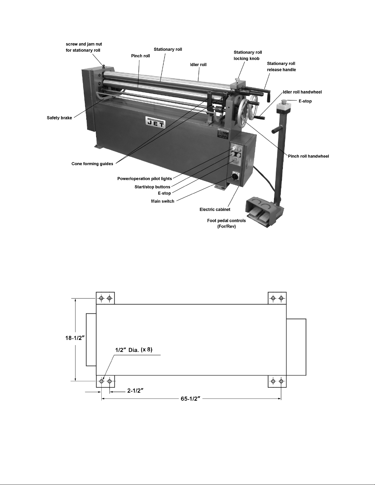
5.0 Features and Terminology
Figure 5-1: Features
6.0 Floor mounting holes
Figure 6-1: Hole centers
6
Page 7

Read and understand the entire
contents of this manual before attem pting setup or operation! Failure to com ply may cause
serious injury.
7.0 Setup and assembly
Open shipping container and check for shipping
damage. Report any damage immediately to your
distributor and shipping agent. Do not discard any
shipping material until the machine is assembled
and running properly.
Compare the contents of your container with the
following parts list to make sure all parts are intact.
Missing parts, if any, should be reported to your
distributor. Read the instruction manual thoroughly
for assembly, maintenance and safety instructions.
7.1 Shipping contents
1 Electric Plate Roller
1 Foot pedal control assembly
1 Operating Instructions and Parts Manual
1 Warranty Card
1 Toolbox (p/n EPR1460-TB), containing:
1 Oil can
1 Adjustable wrench
1 Hex key set
1 Grease gun
8 Hex cap screws
8 Lock washers
8 Flat washers
8 Hex nuts
7.2 Tools required for assembly
Level (not provided)
8.0 Electrical connections
Electrical connections must be
made by a qualified electrician in compliance
with all relevant codes. This machine must be
properly grounded to help prevent electrical
shock and possible fatal injury.
The EPR-1460 Plate Roller is pre-wired for 230-volt,
three-phase operation. It is not provided with a
power plug; you may either attach a proper 230V
UL-listed plug, or “hardwire” the machine directly to
a service panel (make sure a disconnect is available
to the operator).
If used with a plug:
Grounded, cord-connected tools intended for use on
a supply circuit having a nominal rating between
150-250 V inclusive:
This tool is intended for use on a circuit that has an
outlet that looks like the one illustrated in Figure 8-
1. The tool is intended for use with a grounding plug
that looks like the plug illustrated in Figure 8-1. Make
sure the tool is connected to an outlet having the
same configuration as the plug. No adapter is
available or should be used with this tool. If the tool
must be reconnected for use on a different type of
electric circuit, the reconnection should be made by
qualified service personnel; and after reconnection,
the tool should comply with all local codes and
ordinances.
If hardwired:
Permanently connected tools: This tool should be
connected to a grounded metal permanent wiring
system; or to a system having an equipmentgrounding conductor.
7.3 Positioning and cleanup
Remove all crating from around the plate roller, and
use a forklift or hoist with straps to carefully move
the machine off the pallet and into position. Lifting
equipment must be properly rated for weight of
machine.
Position plate roller so there is enough room on all
sides for general maintenance and feeding of
materials. Anchor machine to a stable floor,
preferably concrete, using lag screws or other
appropriate fasteners through the four holes in
base. Level the machine; use shims if needed.
Exposed metal surfaces have been given a
protective coating. Remove this with a soft cloth and
a cleaner-degreaser. Do not use gasoline, paint
thinner or acetone, as these may damage painted
surfaces. Do not use an abrasive pad, as it may
scratch polished surfaces.
7
Figure 8-1: grounding
8.1 Converting to 460V
The plate roller can be converted to 460 volt, as
follows:
1. Before connecting to power source, be sure
switch is in off position. Engage E-stop.
2. Connect the motor leads to the incoming power
source.
3. If using a plug, replace the 230V plug with a
proper 460V, UL-listed plug.
Page 8

It is recommended that the Plate Roller be
connected to a dedicated 10 amp circuit with a
circuit breaker or fuse. If connected to a circuit
protected by fuses, use time delay fuse marked “D”.
NOTE: Local codes take precedence over
recommendations.
8.2 GROUNDING INSTRUCTIONS
This tool must be grounded. In the event of a
malfunction or breakdown, grounding provides a
path of least resistance for electric current to reduce
the risk of electric shock. This tool is equipped with
an electric cord having an equipment-grounding
conductor and a grounding plug. The plug must be
inserted into an appropriate outlet that is properly
installed and grounded in accordance with all local
codes and ordinances.
Improper connection of the
equipment-grounding conductor can result in a
risk of electric shock. Check with a qualified
electrician or service person if you are i n doubt
as to whether t he outlet is pr operly grounded.
Do not modify the plug provided with the tool –
if it will not fit the outlet, have a proper outlet
installed by a qualified electrician.
The conductor wit h insulation having an outer
surface that is green with or without yellow stripes is
the equipment-grounding conductor. If repair or
replacement of the electric cord or plug is
necessary, do not connect the equipment-grounding
conductor to a live terminal.
Use only 3-wire extension cords that have 3-prong
grounding plugs and 3-pole receptacles that accept
the tool's plug.
Repair or replace damaged or worn cord
immediately.
Ampere
Rating
More
Than
00 06 18 16 16 14
06 10 18 16 14 12
10 12 16 16 14 12
12 16 14 12
Not
More
Than
Extension Cord Recommendations
Volts
240 50 100 200 300
AWG
Total length of
cord in feet
Not
Recommended
Table 1
9.0 Operation
9.1 Controls
Power light: Indicates current is flowing to machine.
Operation light: Indicates machine is in motion.
Start/stop button.
Emergency stop: Push E-stop button (one on
control panel, one on foot pedal post) for immediate
shut-down of machine. To re-start machine, rotate
E-stop button clockwise until it disengages. It is
recommended that E-stop buttons be used for
emergency shutdowns; use stop button on electric
box for normal shutdown.
Main switch: When turned on, power light will
illuminate.
Foot pedals: Two pedals for instant forward or
reverse motion.
Safety brake (see Figure 5-1): Machine will shut off
if this is pushed down by operator or contacted by a
workpiece.
8.3 Extension cords
The use of extension cords is discouraged; try to
position equipment within reach of the power
source. If an extension cord becomes necessary, be
sure it is heavy enough to carry the current your
product will draw. An undersized cord will cause a
drop in line voltage resulting in loss of power and
overheating.
Table 1 shows recommended size to use depending
on cord length and nameplate ampere rating. If in
doubt, use the next heavier gauge. The smaller the
gauge number, the heavier the cord.
8
Figure 9-1: control panel
Page 9

9.2 Roll adjustment
π
π
(Figure 5-1 identifies machine elements.)
The front handwheel raises or lowers the pinch roll
(counterclockwise to raise), so that the correct gap
between stationary and pinch rolls may be obtained
to feed the stock into the machine.
The rear handwheel raises or lowers the idler roll
(clockwise to raise) which determines degree of
bend in the stock that is being fed through the
machine. A scale near the rear handwheel will aid
the operator.
To adjust rolls for material thickness:
1. Insert material between the rolls from front of
machine, and raise pinch roll until material fits
tightly.
2. Raise idler roll to desired position for bend.
No exact formula can be followed when making
these roll adjustments because material "spring
back" varies with the kind of material being formed.
Only by test forming several pieces can the correct
adjustments be obtained. Also, keep in mind that it
is much easier to re-pass material to make a smaller
radius than it is to attempt to increase a radius that
was made too small.
Rolls must be adjusted exactly parallel or the
material will spiral during the rolling process. The
gearing and transmission shafts on the EPR-1460
ensure parallel movement as the handwheels are
rotated.
NOTE: Deliberately setting rolls non-parallel is done
to make cone shapes (see sect. 10.6). If rolls have
been adjusted for cone forming, check gap between
rollers with calipers, and reset them to parallel.
The stationary, or top, roll is secured at its left end
with a screw and jam nut (see Figure 1). These have
been positioned by the manufacturer, but can be
adjusted if needed.
10.0 Forming the workpiece
The rolls pr esent a pinch poi nt
and/or crush hazard. Do not place hands in
close proximity to rolls while operating.
For example: To find length of material needed (C)
to form a tube 4" in diameter, multiply 3.1417 by 4".
Result: 12.5667" is the circumference of
approximate length of material needed. Cut several
pieces of material to this length for a forming test
run. Material may have to be lengthened or
shortened depending upon results of the test run.
If workpiece is large, make sure it receives proper
support as it exits machine.
10.2 Flat rolling
Softer metals (copper, aluminum, etc.) can be
processed through the machine to straighten,
flatten, or reduce their thickness. Simply adjust
pinch roll for thickness, lower idler roll to same
height as pinc h roll, and feed workpiece through
(Figure 10-1).
Figure 10-1
10.3 Forming a radius
1. Adjust pinch roll as needed (see sect. 10.6).
2. Turn on machine and insert workpiece from the
front. Make sure stationary roll is rotating
counterclockwise.
3. When material reaches the point where the
radius is to begin (Figure 10-2), stop machine
and raise idler roll to achieve desired bend.
4. Restart rolls and continue until bend is
completed (Figure 10-2). Support workpiece as
it exits machine.
5. If a smaller radius is needed, adjust idler roll
distance and re-feed workpiece.
10.1 Material size considerations
To determine approximate length of material
needed for a desired size tube, use the following
formula:
DC
=
where
and D is the diameter.
C
is the circumference,
equals 3.1417
Figure 10-2
9
Page 10

10.4 Forming a tube
A tube can often be made with a single pass through
the machine, as follows:
1. Adjust pinch roll as needed to accommodate
workpiece thickness.
2. Feed workpiece into machine. As it nears the
end (Figure 10-3a), stop machine and reverse
direction (Figure 10-3b).
Figure 10-3
3. To remove tube from stationary roll:
4. Position cone forming guides out of the way.
5. Loosen knob (A, Figure 10-4), pull handle
upward, then toward front. Pull stationary roll
out of notch.
6. After tube is removed, reposition stationary roll,
making sure handle is rotated back to original
position. Tighten knob (A).
Figure 10-5
10.6 Forming a cone
1. Prepare workpiece to appropriate shape for
desired cone.
2. Adjust idler roll and/or pinch roll to allow more
free space at left end of rolls. This is done by
disengaging clutch coupling, as follows:
Idler roll: Pull pin (C, Figure 10-6) to disengage
from groove. Pull out on handwheel until pin
engages next groove. Rotating handwheel will
now raise or lower right end only of idler roll.
(Reverse procedure to re-engage).
Pinch roll: Loosen set screw in left half of
bushing (D, Figure 10-7), and slide it away. A
flat blade screwdriver may be needed for initial
prying apart. (When re-engaging, use a small
threaded clamp to push halves together, then
tighten set screw.)
3. Slide workpiece against cone forming guide
(Figure 10-8) and tightly clamp workpiece at
right end. Proceed with forming operation.
Figure 10-4
10.5 Bending wire
There are three wire grooves at the end of pinch roll
and idler roll, to accommodate 3/8, 1/2, and 5/8-inch
wire. See Figure 10-5.
Loosen cone forming guide (B, Figure 10-5) and
swing it out of the way or remove it.
Use smallest groove into which wire will comfortably
fit. Bend the wire using same principles as described
for forming a radius. To make a complete loop of
wire, use the instructions for forming a tube.
10
Figure 10-6: Idler roll disengagement
Page 11

Figure 10-7: Pinch roll disengagement
11.0 User-maintenance
11.1 General maintenance
Keep the rolls clean and rust-free, and periodically
apply a light film of oil to their surfaces.
11.2 Lubrication
A general-purpose lithium grease is recommended
for the following:
Keep gears lubricated. (Remove left side cover to
access gears and chain.) Operate machine to
disperse the grease.
Apply grease to right end of stationary roll where it
slides in and out of notch.
Insert grease into each of 5 fittings, shown in Figure
11-1.
11.3 Additional servicing
Any additional servicing should be performed by an
authorized JET service center.
Figure 10-8: cone forming
Figure 11-1: oil fittings
11
Page 12

12.0 Troubleshooting EPR-1460 Plate Roller
Table 2
Symptom Possible Cause Correction *
Machine doesn’t
operate; rolls won’t
move.
Cones are made when
trying to make
cylinders.
Workpiece is not
bending.
No incoming power. Check power source and connections.
Release emergency stop switch by
Emergency stop engaged.
Jam nut is loose. Tighten nut to secure stationary roll.
Gears damaged.
Rolls not parallel.
Machine capacity exceeded.
Idler roll not engaging.
rotating clockwise (check both switch
locations).
Inspect gears; repair/replace as
needed.
Adjust idler (rear) roll as needed until
idler roll is parallel to stationary (top)
roll.
Use materials within machine’s
capacity.
Inspect idler roll; make adjustments as
needed.
* WARNING: Some corrections may require a qualified electrician.
13.0 Replacement Parts
Replacement parts are listed on the following pages. To order parts or reach our service department, call 1-800274-6848 Monday through Friday, 8:00 a.m. to 5:00 p.m. CST. Having the Model Number and Serial Number of
your machine available when you call will allow us to serve you quickly and accurately.
Non-proprietary parts, such as fasteners, can be found at local hardware stores, or may be ordered from JET.
Some parts are shown for reference only, and may not be available individually.
12
Page 13

13.1.1 EPR-1460 Electric Plate Roller – Exploded View
13
Page 14

13.1.2 EPR-1460 Electric Plate Roller – Parts List
Index No. Part No. Description Size Qty
1 ................ EPR1460-1................ Side Cover ............................................................... ...................................... 1
2 ................ TS-2246102 .............. Socket Head Button Screw ...................................... M6x10 ........................... 5
3 ................ TS-1492021 .............. Hex Cap Screw ........................................................ M12x30 ......................... 3
4 ................ EPR1460-4................ Pad .......................................................................... ...................................... 3
5 ................ EPR1460-5................ Big Gear................................................................... 25T ................................ 1
6 ................ EPR1460-6................ Small Gear ............................................................... 20T ................................ 2
7 ................ EPR1460-7................ Bushing .................................................................... ø35xø39x40 mm ........... 1
8 ................ EPR1460-8................ Pad .......................................................................... ...................................... 1
9 ................ EPR1460-9................ Shaft ........................................................................ ...................................... 1
10 .............. EPR1460-10.............. Cover LH.................................................................. ...................................... 1
11 .............. TS-1503041 .............. Socket Head Cap Screw.......................................... M6X16......................... 28
12 .............. EPR1460-12.............. Plate......................................................................... ...................................... 1
13 .............. AP2-16 ...................... Spring pin................................................................. 6x25mm ........................ 2
14 .............. EPR1460-14.............. Bushing .................................................................... ...................................... 8
15 .............. EPR1460-15.............. Supporting Sleeve ................................................... ...................................... 4
16 .............. EPR1460-16.............. Worm Gear .............................................................. ...................................... 4
17 .............. EPR1460-17.............. Spherical Plain Bearing ........................................... GE45DS ........................ 2
18 .............. EPR1460-18.............. Lead Screw .............................................................. ...................................... 2
19 .............. F010433 .................... Socket Set Screw .................................................... M8X40........................... 4
20 .............. EPR1460-20.............. Adjusting Block ........................................................ ...................................... 2
21 .............. EPR1460-21.............. Pad .......................................................................... ...................................... 8
22 .............. EPR1460-22.............. Worm Shaft .............................................................. ...................................... 1
23 .............. EPR1460-23.............. Worm ....................................................................... ...................................... 4
24 .............. EPR1460-24.............. Plate......................................................................... ...................................... 2
25 .............. 130604040 ................ Spring Pin ................................................................ 4X40 mm....................... 4
26 .............. EPR1460-26.............. Transmission Shaft .................................................. ...................................... 2
27 .............. EPR1460-27.............. Rear Roll .................................................................. ...................................... 1
28 .............. EPR1460-28.............. Key........................................................................... 6x25 mm ....................... 4
29 .............. EPR1460-29.............. Trans Shaft Bushing A ............................................. ...................................... 2
30 .............. EPR1460-30.............. Trans Shaft Bushing B ............................................. ...................................... 2
31 .............. TS-155010 ................ Flat Washer ............................................................. 16mm ............................ 4
32 .............. EPR1460-32.............. Pad .......................................................................... ...................................... 1
33 .............. EPR1460-33.............. Joint Bushing ........................................................... ...................................... 4
34 .............. TS-1504041 .............. Socket Head Cap Screw.......................................... M8x20 ........................... 6
35 .............. EPR1460-35.............. Washer .................................................................... ...................................... 2
36 .............. EPR1460-36.............. Handwheel ............................................................... ...................................... 2
37 .............. EPR1460-37.............. Cover RH ................................................................. ...................................... 1
38 .............. 5508737 .................... Double Round Head Key ......................................... 8x8X25 mm ................... 2
39 .............. ESR1650T-41 ........... Double Round Head Key ......................................... 8x8X45 mm ................... 4
40 .............. EPR1460-40.............. Worm Shaft .............................................................. ...................................... 1
41 .............. EPR1460-41.............. Right Support ........................................................... ...................................... 1
42 .............. EPR1460-42.............. Lower Roll ................................................................ ...................................... 1
43 .............. EPR1460-43.............. Bushing .................................................................... ø35xø39x30 mm ........... 4
44 .............. EPR1460-44.............. Adjusting block......................................................... ...................................... 2
45 .............. EPR1460-45.............. Oil fitting ................................................................... Φ8 x1 mm ..................... 1
46 .............. EPR1460-46.............. Bolt........................................................................... ...................................... 1
47 .............. TS-2310201 .............. Hex Nut .................................................................... M20 ............................... 1
48 .............. EPR1460-48.............. Left Support ............................................................. ...................................... 1
49 .............. EPR1460-49.............. Support P late ........................................................... ...................................... 1
50 .............. TS-1504051 .............. Socket Head Cap Screw.......................................... M8X25........................... 4
51 .............. EPR1460-51.............. Shaft ........................................................................ ...................................... 1
52 .............. EPR1460-52.............. Pad .......................................................................... ...................................... 1
53 .............. EPR1460-53.............. Bushing .................................................................... ø40xø44x25 .................. 2
54 .............. EPR1460-54.............. Large Sprocket ........................................................ P=15.875, Z=26 ............ 1
55 .............. EPR1460-55.............. Connecting Rack ..................................................... ...................................... 1
56 .............. TS-2246122 .............. Socket Head Button Screw ...................................... M6X12........................... 4
57 .............. TS-2248162 .............. Socket Head Button Screw ...................................... M8X16........................... 4
58 .............. EPR1460-58.............. Apron ....................................................................... ...................................... 1
59 .............. EPR1460-59.............. Small Lead Screw .................................................... ...................................... 2
60 .............. EPR1460-60.............. Worm Shaft .............................................................. ...................................... 1
14
Page 15

Index No. Part No. Description Size Qty
61 .............. EPR1460-61.............. Plate......................................................................... ...................................... 2
62 .............. EPR1460-62.............. Trans Shaft Bushing ................................................ ...................................... 2
63 .............. EPR1460-63.............. Worm Shaft .............................................................. ...................................... 1
64 .............. TS-2279301 .............. Socket Set Screw .................................................... M10X30......................... 1
65 .............. F005505 .................... Socket Head Cap Screw.......................................... M16x130 ....................... 1
66 .............. EPR1460-66.............. Hand Grip ................................................................ ...................................... 1
67 .............. EPR1460-67.............. Joint Bushing ........................................................... ...................................... 1
68 .............. EPR1460-68.............. Bushing .................................................................... Ø35 xØ39x30 mm .......... 2
69 .............. EPR1460-69.............. Turning Handle ........................................................ ...................................... 1
70 .............. EPR1460-70.............. Pull Rod ................................................................... ...................................... 1
71 .............. TS-1541031 .............. Hex Nut, Ny lon Lock ................................................ M8 ................................. 1
72 .............. TS-1504091 .............. Socket Hd Cap Screw.............................................. M8×45 ........................... 1
73 .............. EPR1460-73.............. Shaft ........................................................................ ...................................... 1
74 .............. EPR1460-74.............. Lock sleeve .............................................................. ...................................... 1
75 .............. TS-1506071 .............. Socket Head Cap Screw.......................................... M12X50......................... 1
76 .............. BB-6001ZZ ................ Bearing .................................................................... 6001-2Z......................... 4
77 .............. TS-1505011 .............. Socket Head Cap Screw.......................................... M10X16......................... 1
78 .............. EPR1460-78.............. Sliding Block ............................................................ ...................................... 1
79 .............. EPR1460-79.............. Guide Roller, Short .................................................. ...................................... 1
80 .............. EPR1460-30.............. Bushing .................................................................... ...................................... 1
81 .............. EPR1460-81.............. Upper Roll ................................................................ ...................................... 1
82 .............. EPR1460-82.............. Adjusting Block ........................................................ ...................................... 1
83 .............. EPR1460-83.............. Bushing .................................................................... ø35xø39x30 mm ........... 2
84 .............. EPR1460-84.............. Pad .......................................................................... ...................................... 1
85 .............. EPR1460-85.............. Stand ....................................................................... ...................................... 1
86 .............. TS-2360121 .............. Flat Washer ............................................................. 12mm ............................ 8
87 .............. TS-1492021 .............. Hex Cap Screw ........................................................ M12x30 ......................... 8
88 .............. TS-2361161 .............. Lock Washer ............................................................ 16mm ............................ 4
89 .............. EPR1460-89.............. Reduction Box & Motor Ass. .................................... ...................................... 1
.................. EPR1460-89-1 .......... Motor, 230/460V-3PH .............................................. 1.5kW, 4P ..................... 1
.................. EPR1460-89-2 .......... Key .......................................................................... 8x30 mm ....................... 1
.................. EPR1460-89-3 .......... Reduction Box ......................................................... ...................................... 1
.................. EPR1460-89-4 .......... Motor Fan Cover (not shown) .................................. ...................................... 1
.................. EPR1460-89-5 .......... Motor Fan (not shown)............................................. ...................................... 1
.................. EPR1460-89-6….. ..... Junction Box (not shown) ........................................ ...................................... 1
.................. EPR1460-89-7 .......... Junction Box Cover (not shown) .............................. ...................................... 1
90 .............. F005491 .................... Socket Head Cap Screw.......................................... M16x35 ......................... 4
91 .............. TS-2361161 .............. Lock Washer ............................................................ 16 mm ........................... 4
92 .............. F009602 .................... Hex Cap Screw ........................................................ M16x40 ......................... 4
93 .............. TS-155010 ................ Flat Washer ............................................................. 16 mm ........................... 8
94 .............. EPR1460-94.............. Support plate ........................................................... ...................................... 1
95 .............. EPR1460-95.............. Small Sprocket......................................................... P=12.875, Z=17 ............ 1
96 .............. EPR1460-96.............. Lock screw ............................................................... M8 x16 ........................... 2
97 .............. EPR1460-97.............. Key........................................................................... 12x45 ............................ 1
98 .............. TS-2311161 .............. Hex Nut .................................................................... M16 ............................... 4
99 .............. TS-1540061 .............. Hex Nut .................................................................... M8 ................................. 2
100 ............ EPR1460-100............ Safety brake............................................................. ...................................... 1
101 ............ EPR1460-101............ Sleeve ...................................................................... ...................................... 2
102 ............ TS-1490071 .............. Hex Cap Screw ........................................................ M8x40 ........................... 2
103 ............ EPR1460-103............ Sleeve ...................................................................... 2520 .............................. 2
104 ............ EPR1460-104............ Adjusting plate ........................................................ ...................................... 1
105 ............ EPR1460-105............ Screw ....................................................................... M12x125 ....................... 1
106 ............ TS-2311101 .............. Hex Nut .................................................................... M10 ............................... 4
107 ............ EPR1460-107............ Guide Roller, Long ................................................... ...................................... 1
108 ............ TS-1503051 .............. Socket Head Cap Screw.......................................... M6x20 ........................... 6
109 ............ EPR1460-109............ Lock Screw .............................................................. ...................................... 1
110 ............ EPR1460-110............ Adjusting Plate ......................................................... ...................................... 1
111 ............ EPR1460-111............ Limit Block ............................................................... ...................................... 1
112 ............ EPR1460-112............ Seat ......................................................................... ...................................... 1
113 ............ EPR1460-113............ Seat ......................................................................... ...................................... 1
114 ............ TS-1503041 .............. Socket Head Cap Screw.......................................... M6X16........................... 2
115 ............ EPR1460-115............ Support Board.......................................................... ...................................... 1
15
Page 16

Index No. Part No. Description Size Qty
116 ............ TS-2311061 .............. Hex Nut .................................................................... M6 ................................. 2
117 ............ EPR1460-117............ Spring ...................................................................... ...................................... 2
118 ............ TS-1550041 .............. Flat Washer ............................................................. 6 mm ............................. 2
119 ............ TS-2236801 .............. Socket Head Cap Screw.......................................... M6x80 ........................... 2
120 ............ EPR1460-120............ Knob S eat ................................................................ ...................................... 1
121 ............ TS-1502041 .............. Socket Head Cap Screw.......................................... M5x16 ........................... 2
122 ............ EPR1460-122............ Spring .................................................................... ...................................... 1
123 ............ EPR1460-123............ Sleeve ...................................................................... ...................................... 1
124 ............ EPR1460-124............ Pin Shaft .................................................................. ...................................... 1
125 ............ 40317-15 ................... Spring Pin ................................................................ 3x14 mm ....................... 1
126 ............ EPR1460-126............ Lock Handle ............................................................. ...................................... 1
127 ............ F005670 .................... Socket Head Cap Screw.......................................... M6x14 ........................... 1
128 ............ TS-1505061 .............. Socket Head Cap Screw.......................................... M10x40 ......................... 4
129 ............ EPR1460-129............ Lock Bolt .................................................................. ...................................... 1
130 ............ F012086 .................... Spring Pin ................................................................ 3x25 mm ....................... 1
131 ............ EPR1460-131............ Star Grip Knob ......................................................... ...................................... 1
132 ............ TS-1524021 .............. Socket Set Screw .................................................... M8X10........................... 4
133 ............ EPR1460-133............ Electric Cabinet........................................................ ...................................... 1
133-1 ......... EPR1460-133-1 ........ Electric Panel ........................................................... ...................................... 1
133-2 ......... EPR1460-133-2 ........ White Indicator ......................................................... K B2-BVB1C 24V ........... 1
133-3 ......... EPR1460-133-3 ........ Green Indicator ........................................................ KB2-BVB3C 24V ........... 1
133-4 ......... EPR1460-133-4 ........ Start Button .............................................................. ZB2-BE101C ................. 1
133-5 ......... EPR1460-133-5 ........ Stop Button .............................................................. ZB2-BE 102C ................. 1
133-6 ......... EPR1460-133-6 ........ Power Switch ........................................................... JFD11-25 ...................... 1
133-7 ......... EPR1460-133-7 ........ Breaker .................................................................... 3P20A ........................... 1
133-8 ......... EPR1460-133-8 ........ Breaker .................................................................... 2P2A ............................. 1
133-9 ......... EPR1460-133-9 ........ Breaker .................................................................... 1P1A ............................. 1
133-10 ....... EPR1460-133-10 ...... Intermediate Relay................................................... JZX-22F/2E AC24V ...... 1
133-11 ....... EPR1460-133-11 ...... Transformer………………………………………..JBR5-60 220V/440/24V ...... 1
133-12 ....... EPR1460-133-12 ...... A.C. Contactor ........................................................ CN63A1a ...................... 2
133-13 ....... EPR1460-133-13 ...... Supplementary Contactor ........................................ CNA-422M .................... 2
133-14 ....... EPR1460-133-14 ...... Thermal Relay ......................................................... RHN-5 3.5-5A ............... 1
133-15 ....... EPR1460-133-15 ...... Junction Terminal .................................................. UK3N20A 16P............... 1
133-16 ....... EPR1460-133-16 ...... Grounding Copper Bar............................................. M4X6............................. 1
133-17 ....... EPR1460-133-17 ...... Strain Relief ............................................................. M18x1.5 ........................ 3
133-18 ....... EPR1460-133-18 ...... Hose Adapter ........................................................... ...................................... 1
133-19 ....... EPR1460-133-19 ...... Flexible Conduit ....................................................... 2m ................................. 1
133-20 ....... EPR1460-133-20 ...... Power Cable ............................................................ 16AWG ................... 2.5m
133-21 ....... EPR1460-133-21 ...... Motor Cable ............................................................. 16AWG ...................... 2m
133-22 ....... EPR1460-133-22 ...... Cable for Microswitch .............................................. 18AWG ................... 1.4m
134 ............ EPR1460-134............ Emergency Switch Assembly .................................. ...................................... 1
135 ............ EPR1460-135............ Pedal Switch Assembly ........................................... ...................................... 2
136 ............ EPR1460-136............ Set Screw ................................................................ M6x65 ........................... 4
137 ............ EPR1460-137............ Switch Box ............................................................... ...................................... 1
138 ............ EPR1460-138............ Post.......................................................................... ...................................... 1
139 ............ EPR1460-139............ Rubber Grip ............................................................. ...................................... 1
140 ............ TS-1502071 .............. Socket Head Cap Screw.......................................... M5x30 ........................... 2
141 ............ F005671 .................... Socket Head Cap Screw.......................................... M5x95 ........................... 2
142 ............ EPR1460-142............ Box Co ver ................................................................ ...................................... 1
143 ............ TS-1534052 .............. Machine Screw, Pan Head. .................................... M6X16........................... 2
144 ............ EPR1460-144............ Microswitch .............................................................. ...................................... 1
145 ............ F001160 .................... Machine Screw, Pan Head ...................................... M3x16 ........................... 4
146 ............ TS-1540011 .............. Hex Nut .................................................................... M3 ................................. 4
147 ............ TS-2361101 .............. Lock Washer ............................................................ 10 mm ........................... 4
148 ............ TS-1550071 .............. Flat Washer ............................................................. 10 mm ........................... 8
149 ............ EPR1460-149............ Chain ....................................................................... 10A-2x84....................... 1
150 ............ EPR1460-150............ Scale (not shown) .................................................... metric/imperial............... 1
.................. JET-203..................... JET Logo (not shown).............................................. 203x84mm .................... 1
.................. LM000220 ................. ID Label, EPR-1460 (not shown) ............................. ...................................... 1
.................. LM000221 ................. Warning Label (not shown) ...................................... ...................................... 1
16
Page 17

.................. EPR1460-TB ............. Tool Box (not shown – includes following items) ..... ...................................... 1
.................. .................................. Oil can...................................................................... ...................................... 1
.................. .................................. Adjustable wrench ................................................... ...................................... 1
.................. .................................. Hex Key Set ............................................................. ...................................... 1
.................. .................................. Grease Gun ............................................................. ...................................... 1
.................. .................................. Hex Cap Screw ........................................................ M12x45 ......................... 8
.................. .................................. Lock Washer ............................................................ M12 ............................... 8
.................. .................................. Flat Washer ............................................................. M12 ............................... 8
.................. .................................. Hex Nut .................................................................... M12 ............................... 8
17
Page 18

14.0 Electrical Connections for EPR-1460 Plate Roller
18
Page 19

15.0 Warranty and Service
JET warrants every product it sells against manufacturers’ defects. If one of our tools needs service or repair, please
contact Technical Service by calling 1-800-274-6846, 8AM to 5PM CST, Monday through Friday.
Warranty Period
The general warranty lasts for the time period specified in the literature included with your product or on the official
JET branded website.
• JET products carry a limited warranty which varies in duration based upon the product. (See chart below)
• Accessories carry a limited warranty of one year from the date of receipt.
• Consumable items are defined as expendable parts or accessories expected to become inoperable within a
reasonable amount of use and are covered by a 90 day limited warranty against manufacturer’s defects.
Who is Covered
This warranty covers only the initial purchaser of the product from the date of delivery.
What is Co vered
This warranty covers any defects in workmanship or materials subject to the limitations stated below. This warranty
does not cover failures due directly or indirectly to misuse, abuse, negligence or accidents, normal wear-and-tear,
improper repair, alterations or lack of maintenance. JET woodworking machinery is designed to be used with Wood.
Use of these machines in the processing of metal, plastics, or other materials may void the warranty. The exceptions
are acrylics and other natural items that are made specifically for wood turning.
Warranty Limitations
Woodworking products with a Five Year Warranty that are used for commercial or industrial purposes default to a
Two Year Warranty. Please contact Technical Service at 1-800-274-6846 for further clarification.
How to Get Technical Support
Please contact Technical Service by calling 1-800-274-6846. Please note t hat you will be asked to pro vi d e pr o of
of initia l p u rch a s e whe n calling. If a product requires further inspection, the Technical Service representative will
explain and assist with any additional action needed. JET has Authorized Service Centers located throughout the
United States. For the name of an Authorized Service Center in your area call 1-800-274-6846 or use the Service
Center Locator on the JET website.
More Information
JET is constantly adding new products. For complete, up-to-date product information, check with your local distributor
or visit the JET website.
How State Law Appli es
This warranty gives you specific legal rights, subject to applicable state law.
Limitations on This Warranty
JET LIMITS ALL IMPLIED WARRANTIES TO THE PERIOD OF THE LIMITED WARRANTY FOR EACH PRODUCT.
EXCEPT AS STATED HEREIN, ANY IMPLIED WARRANTIES OF MERCHANTABILITY AND FITNESS FOR A
PARTICULAR PURPOSE ARE EXCLUDED. SOME STATES DO NOT ALLOW LIMITATIONS ON HOW LONG AN
IMPLIED WARRANTY LASTS, SO THE ABOVE LIMITATION MAY NOT APPLY TO YOU.
JET SHALL IN NO EVENT BE LIABLE FOR DEATH, INJURIES TO PERSONS OR PROPERTY, OR FOR
INCIDENTAL, CONTINGENT, SPECIAL, OR CONSEQUENTIAL DAMAGES ARISING FROM THE USE OF OUR
PRODUCTS. SOME STATES DO NOT ALLOW THE EXCLUSION OR LIMITATION OF INCIDENTAL OR
CONSEQUENTIAL DAMAGES, SO THE ABOVE LIMITATION OR EXCLUSION MAY NOT APPLY TO YOU.
JET sells through distributors only. The specifications listed in JET printed materials and on official JET website are
given as general information and are not binding. JET reserves the right to effect at any time, without prior notice,
those alterations to parts, fittings, and accessory equipment which they may deem necessary for any reason
whatsoever. JET
Product Listing with Warranty Period
90 Days – Parts; Consumable items
1 Year – Motors; Machine Accessories
2 Year – Metalworking Machinery; Electric Hoists, Electric Hoist Accessories; Woodworking Machinery used
for industrial or commercial purposes
5 Year – Woodworking Machinery
Limited Lifetime – JET Parallel clamps; VOLT Series Electric Hoists; Manual Hoists; Manual Hoist
Accessories; Shop Tools; Warehouse & Dock products; Hand Tools; Air Tools
NOTE: JET is a division of JPW Industries, Inc. References in this document to JET also apply to JPW Industries,
Inc., or any of its successors in interest to the JET brand.
®
branded products are not sold in Canada by JPW Industries, Inc.
19
Page 20

427 New Sanford Road
LaVergne, Tennessee 37086
Phone: 800-274-6848
www.jettools.com
20
 Loading...