

Page 1
This .pdf document is bookmarked
Operating Instructions and Parts Manual
50-inch Electrical Slip Roll Machine
Model ESR-1650T-1, ESR-1650T-3
JET
427 New Sanford Road
LaVergne, Tennessee 37086 Part No. M-756027
Ph.: 800-274-6848 Revision C 12/2014
www.jettools.com Copyright © 2014 JET
Page 2

1.0 Warranty and Service
JET warrants every product it sells against manufacturers’ defects. If one of our tools needs service or repair, please
contact Technical Service by calling 1-800-274-6846, 8AM to 5PM CST, Monday through Friday.
Warranty Period
The general warranty lasts for the time period specified in the literature included with your product or on the official
JET branded website.
• JET products carry a limited warranty which varies in duration based upon the product. (See chart below)
• Accessories carry a limited warranty of one year from the date of receipt.
• Consumable items are defined as expendable parts or accessories expected to become inoperable within a
reasonable amount of use and are covered by a 90 day limited warranty against manufacturer’s defects.
Who is Covered
This warranty covers only the initial purchaser of the product from the date of delivery.
What is Co vered
This warranty covers any defects in workmanship or materials subject to the limitations stated below. This warranty
does not cover failures due directly or indirectly to misuse, abuse, negligence or accidents, normal wear-and-tear,
improper repair, alterations or lack of maintenance. JET woodworking machinery is designed to be used with Wood.
Use of these machines in the processing of metal, plastics, or other materials may void the warranty. The exceptions
are acrylics and other natural items that are made specifically for wood turning.
Warranty Limitations
Woodworking products with a Five Year Warranty that are used for commercial or industrial purposes default to a
Two Year Warranty. Please contact Technical Service at 1-800-274-6846 for further clarification.
How to Get Technical Support
Please contact Technical Service by calling 1-800-274-6846. Please note that you will be asked to provide pr o of
of initia l p u rch a s e whe n calling. If a product requires further inspection, the Technical Service representative will
explain and assist with any additional action needed. JET has Authorized Service Centers located throughout the
United States. For the name of an Authorized Service Center in your area call 1-800-274-6846 or use the Service
Center Locator on the JET website.
More Information
JET is constantly adding new products. For complete, up-to-date product information, check with your local distributor
or visit the JET website.
How State Law Appli es
This warranty gives you specific legal rights, subject to applicable state law.
Limitations on This Warranty
JET LIMITS ALL IMPLIED WARRANTIES TO THE PERIOD OF THE LIMITED WARRANTY FOR EACH PRODUCT.
EXCEPT AS STATED HEREIN, ANY IMPLIED WARRANTIES OF MERCHANTABILITY AND FITNESS FOR A
PARTICULAR PURPOSE ARE EXCLUDED. SOME STATES DO NOT ALLOW LIMITATIONS ON HOW LONG AN
IMPLIED WARRANTY LASTS, SO THE ABOVE LIMITATION MAY NOT APPLY TO YOU.
JET SHALL IN NO EVENT BE LIABLE FOR DEATH, INJURIES TO PERSONS OR PROPERTY, OR FOR
INCIDENTAL, CONTINGENT, SPECIAL, OR CONSEQUENTIAL DAMAGES ARISING FROM THE USE OF OUR
PRODUCTS. SOME STATES DO NOT ALLOW THE EXCLUSION OR LIMITATION OF INCIDENTAL OR
CONSEQUENTIAL DAMAGES, SO THE ABOVE LIMITATION OR EXCLUSION MAY NOT APPLY TO YOU.
JET sells through distributors only. The specifications listed in JET printed materials and on official JET website are
given as general information and are not binding. JET reserves the right to effect at any time, without prior notice,
those alterations to parts, fittings, and accessory equipment which they may deem necessary for any reason
whatsoever. JET
Product Listing with Warranty Period
90 Days – Parts; Consumable items; Light-Duty Air Tools
1 Year – Motors; Machine Accessories; Heavy-Duty Air Tools; Pro-Duty Air Tools
2 Year – Metalworking Machinery; Electric Hoists, Electric Hoist Accessories; Woodworking Machinery used
for industrial or commercial purposes
5 Year – Woodworking Machinery
Limited Lifetime – JET Parallel clamps; VOLT Series Electric Hoists; Manual Hoists; Manual Hoist
Accessories; Shop Tools; Warehouse & Dock products; Hand Tools
NOTE: JET is a division of JPW Industries, Inc. References in this document to JET also apply to JPW Industries,
Inc., or any of its successors in interest to the JET brand.
®
branded products are not sold in Canada by JPW Industries, Inc.
2
Page 3

2.0 Table of Contents
1.0 Warranty and Service ....................................................................................................................... 2
2.0 Table of Contents ............................................................................................................................. 3
3.0 Safety warnings ................................................................................................................................ 4
4.0 Introduction ....................................................................................................................................... 5
5.0 Specifications ................................................................................................................................... 6
6.0 Features and Terminology ................................................................................................................ 7
7.0 Floor mounting holes ........................................................................................................................ 7
8.0 Unpacking ........................................................................................................................................ 8
9.0 Electrical Connection ........................................................................................................................ 8
10.0 Operation ........................................................................................................................................ 9
10.1 Roll Adjustment ........................................................................................................................... 9
10.2 Foot Pedal Operation .................................................................................................................. 9
11.0 Forming the Workpiece .................................................................................................................... 9
11.1 Material Size Considerations ....................................................................................................... 9
11.2 Flat Rolling .................................................................................................................................. 9
11.3 Forming a Radius ...................................................................................................................... 10
11.4 Forming a Tube ......................................................................................................................... 10
11.5 Bending Wire............................................................................................................................. 10
12.0 Maintenance ................................................................................................................................. 10
13.0 Troubleshooting the ESR-1650T Slip Roll ..................................................................................... 11
14.0 Replacement Parts ....................................................................................................................... 11
14.1 Assembly Drawing for ESR-1650T ............................................................................................ 12
14.2 Parts List for ESR-1650T ........................................................................................................... 13
15.1 Wiring Diagram for ESR-1650T-1 .................................................................................................. 16
15.2 Wiring Diagram for ESR-1650T-3 .................................................................................................. 17
3
Page 4

3.0 Safety warnings
1. Read and understand the entire owner’s manual before attempting assembly or operation.
2. Read and understand the warnings posted on the machine and in this manual. Failure to comply with
all of these warnings may cause serious injury.
3. Replace the warning labels if they become obscured or removed.
4. This powered slip roll machine is designed and intended for use by properly trained and experienced
personnel only. If you are not familiar with the proper and safe operation of a powered slip roll, do not
use until proper training and knowledge have been obtained.
5. Do not use this powered slip roll for other than its intended use. If used for other purposes, JET
disclaims any real or implied warranty and holds itself harmless from any injury that may result from
that use.
6. Always wear approved safety glasses/face shields while using this powered slip roll machine.
Everyday eyeglasses only have impact resistant lenses; they are not safety glasses.
7. Before operating this powered slip roll machine, remove tie, rings, watches and other jewelry, and roll
sleeves up past the elbows. Remove all loose clothing and confine long hair. Non-slip, steel-toed
footwear, and anti-skid floor strips are recommended.
8. Wear ear protectors (plugs or muffs) during extended periods of operation.
9. Some dust created by power sanding, sawing, grinding, drilling and other construction activities
contain chemicals known to cause cancer, birth defects or other reproductive harm. Some examples
of these chemicals are:
• Lead from lead based paint.
• Crystalline silica from bricks, cement and other masonry products.
• Arsenic and chromium from chemically treated lumber.
Your risk of exposure varies, depending on how often you do this type of work. To reduce your
exposure to these chemicals, work in a well-ventilated area and work with approved safety
equipment, such as face or dust masks that are specifically designed to filter out microscopic
particles.
10. Do not operate this machine while tired or under the influence of drugs, alcohol or any medication.
11. Make certain the switch is in the OFF position before connecting the machine to the power supply.
12. Make certain the machine is properly grounded.
13. The slip roller must be anchored to the floor.
14. Make all machine adjustments or maintenance with the machine unplugged from the power source.
15. Remove adjusting keys and wrenches. Form a habit of checking to see that keys and adjusting
wrenches are removed from the machine before turning it on.
16. Keep safety guards in place at all times when the machine is in use. If removed for maintenance
purposes, use extreme caution and replace the guards immediately.
17. Check damaged parts. Before further use of the machine, a guard or other part that is damaged
should be carefully checked to determine that it will operate properly and perform its intended
function. Check for alignment of moving parts, binding of moving parts, breakage of parts, mounting
and any other conditions that may affect its operation. A guard or other part that is damaged should
be properly repaired or replaced.
18. Provide for adequate space surrounding work area and non-glare, overhead lighting.
19. Keep the floor around the machine clean and free of scrap material, oil and grease.
4
Page 5

20. Don't use in dangerous environment. Don't use power tools in damp or wet locations, or expose them
to rain. Keep work area well lighted.
21. Keep visitors a safe distance from the work area. Keep children away.
22. Make your workshop child proof with padlocks, master switches or by removing starter keys.
23. Give your work undivided attention. Looking around, carrying on a conversation and “horse-play” are
careless acts that can result in serious injury.
24. Do not overreach. Failure to maintain proper working position can cause you to fall into the machine
or allow clothing to get caught, pulling you into the machine.
25. Use the right tool at the correct speed and feed rate. Do not force a tool or attachment to do a job for
which it was not designed. The right tool will do the job better and more safely.
26. Use recommended accessories; improper accessories may be hazardous.
27. Maintain tools with care. Keep the machine clean for the best and safest performance. Follow
instructions for lubricating the slip roller.
28. Deburr any sharp metal edges of the workpiece before placing it into the slip roller. Use leather
gloves when handling workpieces.
29. Keep hands away from the moving rolls.
30. Turn off the machine before cleaning. Use a brush or compressed air to remove chips or debris — do
not use your hands.
31. Do not stand on the machine. Serious injury could occur if the machine tips over.
32. Never leave the machine running unattended. Turn the power off and do not leave the machine until it
comes to a complete stop.
33. Remove loose items and unnecessary work pieces from the area before starting the machine.
Familiariz e you rself with the following safety notices used in this manual:
This means that if precautions are not heeded, it may result in minor injury and/or
possible machine damage.
This means that if precautions are not heeded, it may result in serious injury or possibly
even death.
4.0 Introduction
This manual is provided by JET covering the safe operation and maintenance procedures for the JET
ESR-1650T Powered Slip Roller. This manual contains instructions on installation, safety precautions,
general operating procedures, maintenance instructions and parts breakdown. This machine has been
designed and constructed to provide years of trouble free operation if used in accordance with
instructions set forth in this manual. If there are any questions or comments, please contact either your
local supplier or JET. JET can also be reached at our web site: www.jettools.com.
5
Page 6

5.0 Specifications
Model ................................................................ ESR-1650T-1 ............................................. ESR-1650T-3
Stock Number............................................................. 756027 ...................................................... 756028
Construction:
Frame ................................................................... cast iron ..................................................... cast iron
Rolls ......................................... steel, ground and polished ......................... steel, ground and polished
Capacities:
Maximum Thickness – Mild Steel ...........16 gauge (1.5mm) ...................................... 16 gauge (1.5mm)
Maximum Forming Length............................ 50” (1300mm) ............................................ 50” (1300mm)
Number of rolls ................................................................ 3 ................................................................ 3
Diameter of Rolls ............................................... 3” (75mm) .................................................. 3” (75mm)
Minimum Forming Radius (in.) ...........................2” (51mm) ................................................. 2” (51mm)
Wire Grooves (in.) ........................................ 1/2” (12.8mm) ............................................ 1/2” (12.8mm)
.............................................................. 3/8” (9.6mm) .............................................. 3/8” (9.6mm)
............................................................... 5/16” (8mm) ............................................... 5/16” (8mm)
Motor and Controls:
Motor ........................................................ TEFC, Induction ......................................... TEFC, Induction
Horsepower ............................................... 1.5 HP (1.1kW) ............................................ 1HP (0.75kW)
Phase ........................................................................ 1 PH .......................................................... 3 PH
Cycle ......................................................................... 60Hz .......................................................... 60Hz
Voltage ..................................... 115/230V (prewired 230V) ..........................230/460V (prewired 230V)
Full Load Amps ................................................13.78 / 6.89 .................................................. 3.48 / 1.74
Motor RPM ................................................................ 1680 .......................................................... 1680
Control ............................ Foot Pedal with Emergency Stop ............... Foot Pedal with Emergency Stop
Gear Reducer Ratio .................................................... 1:80 ........................................................... 1:80
Driven Roll Speed (RPM) ............................................... 22 .............................................................. 22
Dimensions:
Shipping ............... 71”Lx24”Wx43”H (1800x600x1100mm) ..... 71”Lx24”Wx43
Assembled .............. 65”Lx20”Wx36”H (1660x500x910mm) ....... 65”Lx20”Wx36”H (1660x500x910mm)
Weights:
Net ......................................................... 750 lbs (340 kgs) ....................................... 750 lbs (340 kgs)
Shipping ................................................. 877 lbs (398 kgs) ....................................... 877 lbs (398 kgs)
The specifications in this manual were current at time of publication, but because of our policy of continuous
improvement, JET reserves the right to effect, at any time and without prior notice, changes or alterations to parts,
fittings, and accessory equipment deemed necessary, without incurring obligations.
”H (1800x600x1100mm)
Read and understand the entire contents of this manual before attempting
assembly or operat io n! Failure to comply may cause serious injury!
6
Page 7

6.0 Features and Terminology
Figure 1 - Features
7.0 Floor mounting holes
Figure 2 – Hole centers
7
Page 8

8.0 Unpacking
Open shipping container and check for shipping
damage. Report any damage immediately to
your distributor and shipping agent. Do not
discard any shipping material until the Slip Roll
is assembled and running properly.
Compare the contents of your container with the
following parts list to make sure all parts are
intact. Missing parts, if any, should be reported
to your distributor. Read the instruction manual
thoroughly for assembly, maintenance and
safety instructions.
Contents of container:
1 Electric Slip Roll
1 Foot pedal control assembly
2 Keys to electrical box
1 Instruction and parts manual
1 Warranty card
Remove all crating from around the slip roller,
and use a forklift or hoist with straps to carefully
move the machine off the pallet and into
position. Lifting equipment should be rated for at
least 900 pounds.
It is recommended that the ESR-1650T-1, when
operated at 115V, be connected to a dedicated
20 amp circuit with a 20 amp circuit breaker or
time delay fuse. When operated at 230V,
connect to a dedicated 15 amp circuit with a 15
amp circuit breaker or time delay fuse. Local
codes take precedence over recommendations.
Figure 3
Position the machine so that there is enough
room on all sides for general maintenance and
feeding of materials. Anchor the slip roller to the
floor using lag screws or other appropriate
fasteners through the four holes in the base.
Exposed metal surfaces have been given a
protective coating. Remove this with a soft cloth
and a cleaner-degreaser. Do not use gasoline,
paint thinner, acetone, etc., as these may
damage painted surfaces. Do not use an
abrasive pad, as it may scratch polished
surfaces.
9.0 Electrical Connection
Electri cal power connections
should be made by a qualified electrician.
Observe national and local electrical codes
when connecting this machine.
Single phase model: The ESR-1650T-1 is pre-
wired for 230 volt. It can be converted to 115
volt, as follows:
1. Disconnect machine from power source.
2. Open the control box, and pull down (shut
off) the 230V breaker switch. Switch on the
115V breaker. See Figure 3.
3. On the front of the machine, turn the rotary
dial to 115V (Figure 4).
4. Make sure a proper UL-listed plug is
installed.
Figure 4
Three ph ase model: The ESR-1650T-3 is pre-
wired for 230 volt. It is not provided with a power
plug; you may either attach a proper 230V ULlisted plug, or “hardwire” the machine directly to
a service panel (make sure a disconnect is
available to the operator).
The three-phase model can be converted to 460
volt, as follows:
1. Connect the motor leads according to the
diagram affixed to the motor.
2. On the transformer, remove the wire
terminal from the 230V contact and connect
to the 460V contact.
3. On the thermal relay, make sure the dial is
set to the proper amperage.
4. If using a plug, install a proper 460V, ULlisted plug.
8
Page 9

It is recommended that the ESR-1650T-3, when
π
=
π
D
operated at either voltage, be connected to a
dedicated 15 amp circuit with a 15 amp circuit
breaker or time delay fuse. Local codes take
precedence o ver recommendations.
Push the emergency stop button for fast shut
down of the slip roller. To re-start the machine,
rotate the emergency stop button clockwise until
it releases.
Refer to the Wiring Diagram at the back of this
manual for more detailed wiring information.
10.0 Operation
10.1 Roll Adjustment
(Figure 1 identif ies m ac hine elem ents.)
Four adjustment screws (two in front and two in
the rear) have been built into the left and right
side frames.
The two front adjusting screws enable the
operator to raise or lower the pinch roll, so that
the correct gap between the stationary and
pinch rolls may be obtained to feed the desired
stock into the machine.
The rear adjusting screws raise or lower the idler
roll which determines the degree of bend in the
stock that is being fed through the machine. The
right and left side frames are each equipped with
a scale to aid the operator in determining.
To adjust the rolls for material thickness:
1. Insert the material between the rolls from the
front of the machine and raise the pinch roll
until the material fits tightly.
2. Raise the idler roll equal amounts at each
end, to desired position for the bend.
No exact formula can be followed when making
these roll adjustments because material "spring
back" varies with the kind of material being
formed. Only by test forming several pieces can
the correct adjustments be obtained. Also, keep
in mind that it is much easier to re-pass material
to make a smaller radius than it is to attempt to
increase a radius that was made too small.
Rolls must be adjusted exactly parallel or the
material will spiral during the rolling process.
Measure each end of the opening with calipers if
greater precision is required.
NOTE: Deliberately setting the rolls non-parallel
can be used to make cone shapes.
11.0 Forming the Workpiece
The rolls present a pinch
point and/or crush hazard. Do not place
hands in close proximity to the rolls while
operating.
11.1 Material Size Considerations
To determine the approximate length of material
needed for a desired size tube, use the following
formula:
where
and
For example: To find the length of material
needed (C) to form a tube 4" in diameter,
multiply 3.1417 by 4". Result: 12.5667" is the
circumference of approximate length of material
needed. Cut several pieces of material to this
length for a forming test run. Material may have
to be lengthened or shortened depending upon
results of the test run.
If the workpiece is large, make sure it receives
proper support as it exits the slip roll machine.
11.2 Flat Rolling
Softer metals (copper, aluminum, etc.) can be
processed through the slip roll machine to
straighten, flatten, or reduce their thickness.
Simply adjust the pinch roll for thickness, lower
the idler roll all the way down, and feed the
workpiece through (Figure 5).
NOTE: The idler roll will not descend completely
out of the path of the workpiece; thus, there may
be a slight bend in the workpiece. By flipping the
workpiece over and re-feeding it, this bend can
be minimized.
DC
is the circumference,
C
equals 3.1417
is the diameter.
The stationary, or top, roll is secured at its left
end to the gear side of the machine with the cap
screw and jam nut (see Figure 1). These can be
adjusted if needed.
10.2 Foot Pedal Operation
The shrouded foot control has pedals for instant
forward or reverse motion.
9
Figure 5
Page 10
11.3 Forming a Radius
1. Adjust the pinch roll as needed.
2. Turn on the slip roller and insert the
workpiece from the front. Make sure the
stationary roll is rotating counter-clockwise.
3. When the material reaches the point where
the radius is to begin (Figure 6a), stop the
machine and raise the idler roll an equal
amount on each end to achieve the desired
bend.
Figure 8
4. Re-start the rolls and continue until the bend
is completed (Figure 6b). Support the
workpiece as it exits the machine.
5. If a smaller radius is needed, adjust the roll
distance and re-feed the workpiece.
Figure 6
11.4 Forming a Tube
A tube can often be made with a single pass
through the machine, as follows:
1. Adjust the pinch roller as needed to
accommodate workpiece thickness.
2. Feed the workpiece into the machine. As it
nears the end (Figure 7a), stop the machine
and reverse direction (Figure 7b).
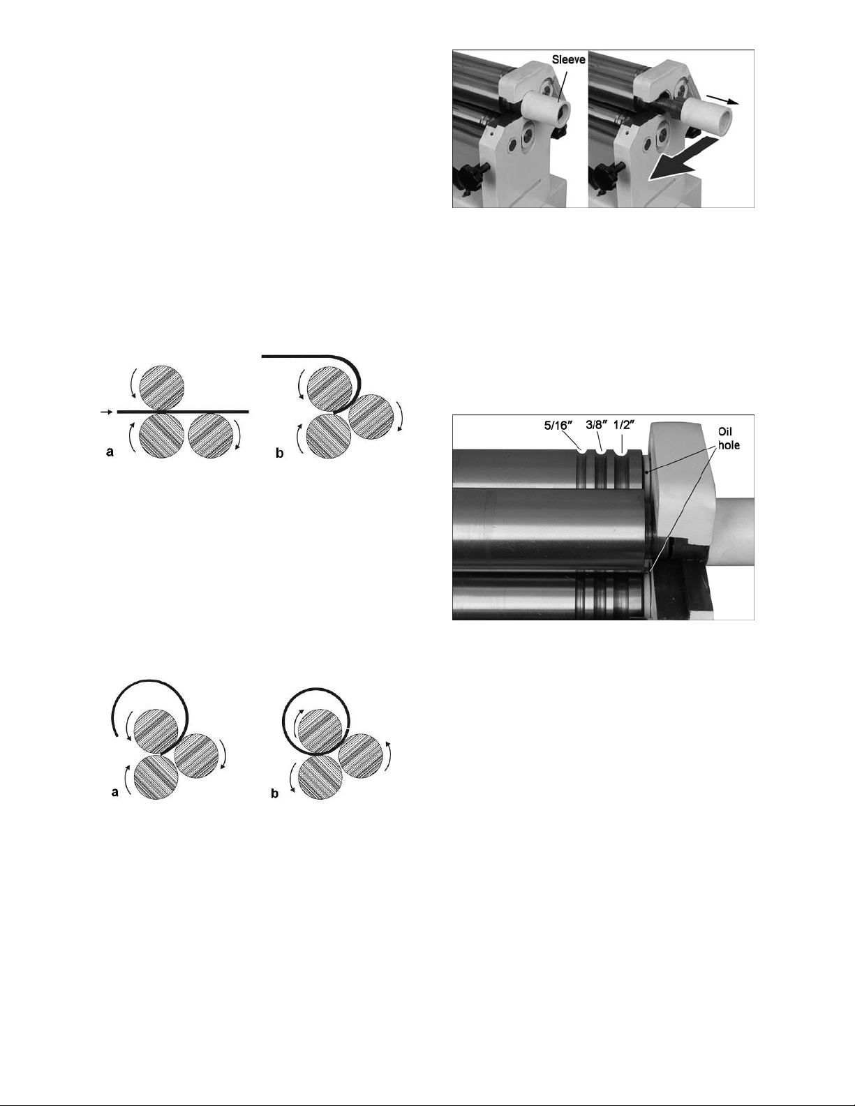
11.5 Bending Wire
There are three wire grooves at the end of the
pinch roll and idler roll, to accommodate a 5/16”,
3/8” and 1/2” wire. See Figure 9.
Use the smallest groove into which the wire will
comfortably fit. Bend the wire using the same
principles as described for forming a radius. To
make a complete loop of wire, use the
instructions for forming a tube.
Figure 9
12.0 Maintenance
Figure 7
3. To remove the tube from the stationary roll,
pull the sleeve outward until it clears the end
bracket; then pivot the roll outward, as
shown in Figure 8.
4. After the tube is removed, reposition the
stationary roll, making sure the sleeve is
pushed back in completely, as shown in
Figure 8.
1. Keep the rolls clean and rust-free, and
periodically apply a light film of oil.
2. Place a few drops of 30W oil into the holes
at each end of the rolls (see Figure 9). Then
operate the machine for a few seconds to
distribute the oil.
3. Apply a light coat of oil to the exposed end
of the stationary roll beneath the sleeve
(shown in Figure 8).
4. Keep the gears lubricated with a good
quality, non-hardening grease. (Remove end
cover to access gears and chain.) Operate
the machine to disperse the grease.
5. Apply a light coat of grease to the pinch roll
and idler roll adjustment screws (see Figure
1).
10
Page 11

13.0 Troubleshooting the ESR-1650T Slip Roll
Trouble Probable Cause Remedy
Slip roll doesn’t
operate; rolls won’t
move.
Cones are made
when trying to make
cylinders.
Workpiece is not
bending.
No incoming power.
Emergency stop engaged.
Jam nut is loose. Tighten nut to secure stationary roll.
Gears damaged.
Rolls not parallel.
Machine capacity exceeded.
Idle Roll not engaging.
Check power source and
connections.
Release emergency stop switch by
rotating clockwise (check both switch
locations).
Inspect gears; repair/replace as
needed.
Adjust idle (rear) roll as needed until
idle roll is parallel to stationary (top)
roll.
Use materials within machine’s
capacity.
Inspect idle roll; make adjustments as
needed.
14.0 Replacement Parts
Replacement parts are listed on the following pages. To order parts or reach our service department, call
1-800-274-6848, Monday through Friday (see our website for business hours, www.jettools.com). Having
the Model Number and Serial Number of your machine available when you call will allow us to serve you
quickly and accurately.
11
Page 12

14.1 Assembly Drawing for ESR-1650T
12
Page 13

14.2 Parts List for ESR-1650T
Index No Part No Description Size Qty
1 ............... ESR1650T-1 ............... Side Cover ......................................................................................... 1
2 ............... ESR1650T-2 ............... Electric Box ........................................................................................ 1
2-1............ ESR1650T-2-1 ............ Short & Overload Protection ............................W1A............................ 1
2-2............ ESR1650T-2-2 ............ Junction Terminal ............................................................................... 1
2-3............ ESR1650T/3-2-3 ......... A.C. Contactor .................................................three phase ................ 3
................. ESR1650T/1-2-3 ......... A.C. Contactor .................................................single phase ............... 4
2-4............ ESR1650T/3-2-4 ......... Thermal Relay .................................................2.4-3.6A (3PH) ........... 1
................. ESR1650T/1-2-4 ......... Thermal Relay .................................................5.5-8.5A (1PH) ........... 1
2-5............ ESR1650T/3-2-5 ......... Transformer ....................................................AC 460 230/24V ......... 1
................. ESR1650T/1-2-5 ......... Transformer ....................................................AC 230 115/24V ......... 1
2-6............ ESR1650T-2-6 ............ Power Indicator ...............................................AC24V........................ 2
2-7............ ESR1650T-2-7 ............ Power On/Off Button .......................................25A ............................ 2
2-8............ ESR1650T-2-8 ............ Strain Relief ....................................................M18 ............................ 3
2-9............ ESR1650T/3-2-9 ......... Strain Relief for 230/460V-3PH .......................M18 ............................ 1
................. ESR1650T/1-2-9 ......... Strain Relief for 115/230V-1PH .......................M20 ............................ 1
2-10 .......... ESR1650T-2-10 .......... Cable for Foot Pedal........................................Ø16 mm ..................... 1
2-11 .......... ESR1650T/3-2-11 ....... Motor Cable..........................................4x1.5mm 230/460V-3PH ......... 1
................. ESR1650T/1-2-11 ....... Motor Cable..........................................7x1.5mm 115/230V-1PH ......... 1
2-12 .......... ESR1650T-2-12 .......... Cable for Microswitch ......................................................................... 1
2-13 .......... ESR1650T/3-2-13 ....... Power Cord for 3 PH..............................4x1.5mm 230/460V-3PH ....... 1
................. ESR1650T/1-2-13 ....... Power Cord for 1 PH..............................3x1.5mm 115/230V-1PH ....... 1
2-14 .......... TS-1532032
3 ............... ESR1650T-3 ............... Stand ................................................................................................. 1
4 ............... ESR1650T-4 ............... Left Support ....................................................................................... 1
5 ............... ESR1650T-5 ............... Right Support ..................................................................................... 1
6 ............... ESR1650T-6 ............... Rear Roll ............................................................................................ 1
7 ............... ESR1650T-7 ............... Upper Roll .......................................................................................... 1
8 ............... ESR1650T-8 ............... Safety Bracket .................................................................................... 1
9 ............... ESR1650T-9 ............... Lower Roll .......................................................................................... 1
10 ............. ESR1650T-10 ............. Square Bushing Upper Roll ................................................................ 1
11 ............. ESR1650T-11 ............. Bushing Rear Roll .............................................................................. 2
12 ............. ESR1650T-12 ............. Bushing Lower Roll ............................................................................ 2
13 ............. ESR1650T-13 ............. Left Bushing Trans Shaft .................................................................... 1
................. ESR1650T-13A ........... Left Bushing Trans Shaft
14 ............. ESR1650T-14 ............. Right Bushing Trans Shaft .................................................................. 1
................. ESR1650T-14A ........... Right Bushing Trans Shaft
15 ............. ESR1650T-15 ............. Sleeve Handle .................................................................................... 1
16 ............. ESR1650T-16 ............. Large Sprocket ................................................P=19.05 Z=25............. 1
17 ............. ESR1650T-17 ............. Small Sprocket ................................................P=19.05 Z=13............. 1
18 ............. ESR1650T/3-18 .......... Motor, 220/440V-3PH ......................................0.75kW, 4P ................. 1
................. ESR1650T/1-18 .......... Motor, 115/230V-1PH ......................................1.1kW, 4P................... 1
18-1 .......... ESR1650T-18-1 .......... Motor Fan Cover ................................................................................ 1
18-2 .......... ESR1650T-18-2 .......... Motor Fan........................................................................................... 1
18-3 .......... ESR1650T-18-3 .......... Housing Cover ................................................................................... 1
18-4 .......... ESR1650T/3-18-4 ....... Stator ..............................................................230/460V-3PH ............ 1
................. ESR1650T/1-18-4 ....... Stator ..............................................................115/230V-1PH ............ 1
18-5 .......... ESR1650T/3-18-5 ....... Rotor ...............................................................230/460V-3PH ............ 1
................. ESR1650T/1-18-5 ....... Rotor ...............................................................115/230V-1PH ............ 1
18-6 .......... ESR1650T-18-6 .......... Flange Plate ....................................................................................... 1
18-7 .......... ESR1650T-18-7 .......... Flange Plate Input Shaft ..................................................................... 1
18-8 .......... BB-6205...................... Ball Bearing .....................................................Φ52XΦ25X15 ............. 1
18-9 .......... ESR1650T-18-9 .......... Reducer Cover ................................................................................... 1
18-10 ........ ESR1650T-18-10 ........ O-ring ..............................................................Φ180XΦ2.6 mm ......... 1
18-11 ........ ESR1650T-18-11 ........ Bushing .............................................................................................. 1
18-12 ........ ESR1650T-18-12 ........ Gear ................................................................................................... 1
18-13 ........ BB-6207...................... Ball Bearing .....................................................Φ72XΦ35X7 mm ........ 1
................ Phillips Pan Head Machine Screw ...................M4x10 ...................... 12
(for serial nos. over 11110037) ........................ 1
(for serial nos. over 11110037) ..................... 1
13
Page 14

Index No Part No Description Size Qty
18-14 ........ ESR1650T-18-14 ........ Housing .............................................................................................. 1
18-15 ........ ESR1650T-18-15 ........ Oil Seal ...........................................................Φ50XΦ35X7 mm ........ 1
18-16 ........ ESR1650T-18-16 ........ Key .................................................................8x25 mm .................... 1
18-17 ........ ESR1650T-18-17 ........ Output Shaft ....................................................................................... 1
18-18 ........ BB-6301...................... Ball Bearing .....................................................Φ37XΦ12X12 ............. 3
18-19 ........ ESR1650T-18-19 ........ Gear Shaft .......................................................................................... 1
18-20 ........ BB-6303...................... Ball Bearing .....................................................Φ52XΦ15X12 ............. 1
18-21 ........ ESR1650T-18-21 ........ Key .................................................................5X12 mm .................... 1
18-22 ........ ESR1650T-18-22 ........ Gear Shaft .......................................................................................... 1
18-23 ........ ESR1650T-18-23 ........ Gear ................................................................................................... 1
18-24 ........ ESR1650T-18-24 ........ Gear ................................................................................................... 1
18-25 ........ TS-1503061 ................ Socket Head Cap Screw..................................M6X25........................ 3
18-26 ........ ESR1650T-18-26 ........ Bolt .................................................................M5X25........................ 3
18-27 ........ ESR1650T-18-27 ........ Oil Seal ...........................................................Φ37XΦ17X7 ............... 1
18-28 ........ BB-6208...................... Ball Bearing .....................................................Φ80XΦ40X18 ............. 1
18-29 ........ BB-6205...................... Ball Bearing .....................................................Φ52XΦ
18-30 ........ ESR1650T-18-30 ........ Screw ..............................................................M4X8 ......................... 3
18-31 ........ ESR1650T-18-31 ........ Connecting Shaft ................................................................................ 1
18-32 ........ ESR1650T/1-18-32 ..... Centrifugal Switch for 1PH only .......................................................... 1
18-33 ........ ESR1650T/1-18-33 ..... Start Capacitor for 1PH only ............................35uf ............................ 1
18-34 ........ ESR1650T/1-18-34 ..... Run Capacitor for 1PH only .............................200uf .......................... 1
19 ............. ESR1650T-19 ............. Motor Mount ....................................................................................... 1
20 ............. ESR1650T-20 ............. Gear ................................................................m=2.5 z=30 ................ 1
21 ............. ESR1650T-21 ............. Drive Gear ......................................................m=2.5 z=30 ................ 1
22 ............. ESR1650T-22 ............. Driven Gear .....................................................m=2.5 z=18 ................ 2
23 ............. ESR1650T-23 ............. Gear Wheel Shaft ............................................................................... 1
24 ............. TS-1550071 ................ Flat W asher .....................................................Φ10 mm ..................... 6
25 ............. ESR1650T-25 ............. Adjusting Washer ............................................Φ35XΦ25.5X5 mm ..... 1
26 ............. ESR1650T-26 ............. Bolt for Adjusting Roller ...................................................................... 2
27 ............. ESR1650T-27 ............. Bolt for Auxiliary Roller ....................................................................... 2
28 ............. ESR1650T-28 ............. Transmission Shaft ............................................................................. 1
29 ............. ESR1650T-29 ............. Washer .............................................................................................. 1
30 ............. ESR1650T-30 ............. Bushing .............................................................................................. 2
31 ............. ESR1650T-31 ............. Handle ............................................................................................... 4
32 ............. ESR1650T-32 ............. Pin ..................................................................................................... 4
33 ............. ESR1650T-33 ............. Bolt .................................................................M12X55 ...................... 1
34 ............. TS-1524051 ................ Set Screw........................................................M8x20 ........................ 2
35 ............. TS-1491021 ................ Hex Cap Screw ...............................................M10x20 ...................... 5
36 ............. ESR1650T-36 ............. Bolt .................................................................M12x25 ...................... 4
37 ............. ESR1650T-37 ............. Bushing .............................................................................................. 1
38 ............. ESR1650T-38 ............. Screw ..............................................................M8X40........................ 2
39 ............. TS-1492031 ................ Hex Cap Screw ...............................................M12X35 ...................... 4
40 ............. TS-2360121 ................ Flat W asher .....................................................Φ12 mm ..................... 8
41 ............. ESR1650T-41 ............. Key .................................................................8X45 mm .................... 1
42 ............. ESR1650T-42 ............. Key .................................................................6X25 mm .................... 3
43 ............. ESR1650T-43 ............. Key .................................................................6X40 mm .................... 1
44 ............. TS-2311081 ................ Nut ..................................................................M8 ............................. 2
45 ............. TS-1550061 ................ Flat W asher .....................................................Φ8 mm ....................... 4
46 ............. ESR1650T-46 ............. Worm Rod .......................................................................................... 2
47 ............. ESR1650T-47 ............. Lock Spring ........................................................................................ 2
48 ............. ESR1650T-48 ............. Flat Washer ........................................................................................ 4
49 ............. ESR1650T-49 ............. Chain ................................................................................................. 1
50 ............. ESR1650T-50 ............. Emergency Switch .............................................................................. 1
51 ............. ESR1650T-51 ............. Pole ................................................................................................... 1
52 ............. ESR1650T-52 ............. Box Cover .......................................................................................... 1
53 ............. ESR1650T-53 ............. Pedal Switch ...................................................................................... 1
54 ............. TS-1540081 ................ Nut ..................................................................M12 ............................ 1
55 ............. ESR1650T-55 ............. Wheel................................................................................................. 2
56 ............. TS-1540041 ................ Flat W asher .....................................................Φ6 mm ....................... 5
25X12 ............. 2
14
Page 15

Index No Part No Description Size Qty
57 ............. TS-2246162 ................ Socket Head Button Screw ..............................M6X16........................ 5
58 ............. TS-1505051 ................ Socket Head Cap Screw..................................M10x35 ...................... 4
59 ............. ESR1650T-59 ............. Connecting Bushing ........................................................................... 2
60 ............. ESR1650T-60 ............. Fixing Screw....................................................M6x8 .......................... 2
61 ............. ESR1650T-61 ............. Cross Head Screw ..........................................M6x65 ........................ 4
62 ............. ESR1650T-62 ............. Handle Sleeve .................................................................................... 1
63 ............. TS-2285302 ................ Phillips Pan Head Machine Screw ...................M5x30 ........................ 2
64 ............. ESR1650T-64 ............. Cross Head Screw ..........................................M5x95 ........................ 2
65 ............. TS-1534052 ................ Phillips Pan Head Machine Screw ...................M6x16 ........................ 4
66 ............. TS-1482041 ................ Hex Cap Screw ...............................................M6x20 ........................ 1
67 ............. TS-1540041 ................ Flat W asher .....................................................Φ6 mm ....................... 1
68 ............. ESR1650T-68 ............. Switch Box ......................................................................................... 1
69 ............. ESR1650T-69 ............. Rivet for Scale .................................................Ф2×6 mm ................... 4
70 ............. ESR1650T-70 ............. Scale .................................................................................................. 2
71 ............. TS-1490031 ................ Hex Cap Screw ...............................................M8×20 ........................ 2
72 ............. TS-1482031 ................ Hex Cap Screw ...............................................M6×16 ........................ 2
73 ............. ESR1650T-73 ............. Microswitch ........................................................................................ 2
74 ............. ESR1650T-74 ............. Microswitch Mount .............................................................................. 1
75 ............. ESR1650T-75 ............. Washer ...........................................................Φ6 mm ....................... 2
76 ............. ESR1650T-76 ............. Screw ..............................................................M4X10........................ 4
77 ............. ESR1650T-GBA.......... Gear Box Assembly (#18-7 thru 18-28, and 18-31) ............................. 1
15
Page 16

15.1 Wiring Diagram for ESR-1650T-1
(Single Phase only)
16
Page 17

15.2 Wiring Diagram for ESR-1650T-3
(Three Phase only)
17
Page 18

This page intentionally left blank.
18
Page 19

This page intentionally left blank.
19
Page 20

427 New Sanford Road
LaVergne, Tennessee 37086
Phone: 800-274-6848
www.jettools.com
20
 Loading...