

Page 1
OWNER'S MANUAL
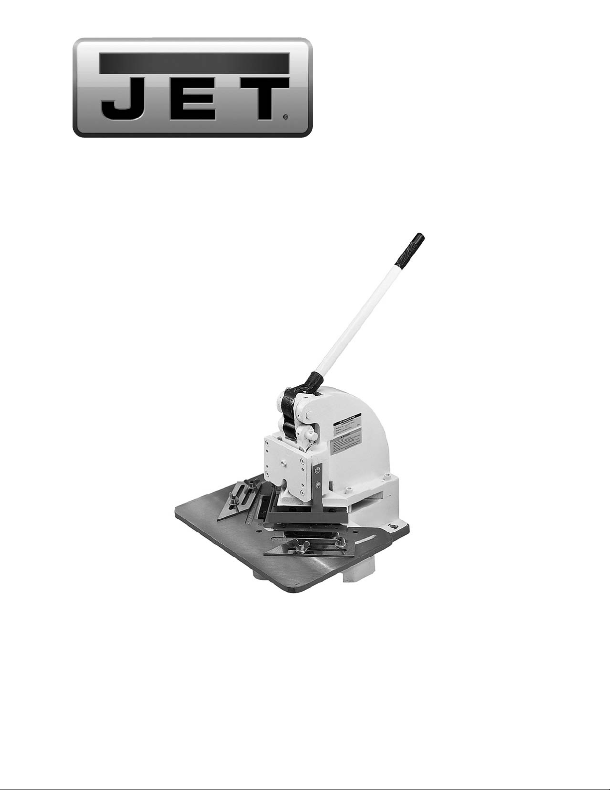
HN-16T Hand Notcher
JET
427 New Sanford Road
LaVergne, Tennessee 37086 Part No. M-756016
Ph.: 800-274-6848 Revision A1 08/2014
www.jettools.com Copyright © 2014 JET
Page 2

Warranty and Service
JET warr ants every prod uct it sells against manu facturers’ d efects. If one of our tools n eeds service or r epair, please
contact Technical Service by calling 1-800-274-6846, 8AM to 5PM CST, Monday through Friday.
Warranty Period
The general warranty lasts for the time period specified in the literature included with your product or on the official
JET branded website.
• JET products carry a limited warranty which varies in duration based upon the product. (See chart below)
• Accessories carry a limited warranty of one year from the date of receipt.
• Consumable items are defined as expendable parts or accessories expected to become inoperable within a
reasonable amount of use and are covered by a 90 day limited warranty against manufacturer’s defects.
Who is Covered
This warranty covers only the initial purchaser of the product from the date of delivery.
What is Co vered
This warranty co vers a ny def ects in wor kman ship o r mat er ials subject to the limitations s tated bel ow. This wa r ranty
does not cover failures due directly or indirectly to misuse, abuse, negligence or accidents, normal wear-and-tear,
improper repair, alterations or lack of maintenance. JET woodworking machinery is designed to be used with Wood.
Use of these machines in the processing of metal, plastics, or other materials may void the warranty. The exceptions
are acrylics and other natural items that are made specifically for wood turning.
Warranty Limitations
Woodworking products with a Five Year Warranty that are used for commercial or industrial purposes default to a
Two Year Warranty. Please contact Technical Service at 1-800-274-6846 for further clarification.
How to Get Technical Support
Please contact Technical Service by calling 1-800-274-6846. Please note that you will be asked to provide pro of
of initial purchase when calling. If a product requires furth er i ns p ection, the Technical Servi c e r epr esent a tive will
explain and assist with any additional action needed. JET has Authorized Service Centers located throughout the
United States. For the name of an Authorized Service Center in your area call 1-800-274-6846 or use the Service
Center Locator on the JET website.
More Informa t ion
JET is constantly adding new products. For complete, up-to-date product information, check with your local distributor
or visit the JET website.
How S tate Law A pplies
This warranty gives you specific legal rights, subject to applicable state law.
Limitations on This Warranty
JET LIMITS ALL IMPLIED WARRANTIES TO THE PERIOD OF THE LIMITED WARRANTY FOR EACH PRODUCT.
EXCEPT AS STATED HEREIN, ANY IMPLIED WARRANTIES OF MERCHANTABILITY AND FITNESS FOR A
PARTICULAR PURPOSE ARE EXCLUDED. SOME STATES DO NOT ALLOW LIMITATIONS ON HOW LONG AN
IMPLIED WARRANTY LASTS, SO THE ABOVE LIMITATION MAY NOT APPLY TO YOU.
JET SHALL IN NO EVENT BE LIABLE FOR DEATH, INJURIES TO PERSONS OR PROPERTY, OR FOR
INCIDENTAL, CONTINGENT, SPECIAL, OR CONSEQUENTIAL DAMAGES ARISING FROM THE USE OF OUR
PRODUCTS. SOME STATES DO NOT ALLOW THE EXCLUSION OR LIMITATION OF INCIDENTAL OR
CONSEQUENTIAL DAMAGES, SO THE ABOVE LIMITATION OR EXCLUSION MAY NOT APPLY TO YOU.
JET sells through distributors only. The specifications listed in JET printed materials and on official JET website are
given as general information and are not binding. JET reserves the right to effect at any time, without prior notice,
those alterations to parts, fittings, and accessory equipment which they may deem necessary for any reason
whatsoever. JET
Product Listing with Warranty Period
90 Days – Parts; Consumable items; Light-Duty Air Tools
1 Year – Motors; Machine Accessories; Heavy-Duty Air Tools; Pro-Duty Air Tools
2 Year – Metalworking Machinery; Electric Hoists, Electric Hoist Accessories; Woodworking Machinery used
for industrial or commercial purposes
5 Year – Woodworking Machinery
Limited Lifetime – JET Parallel clamps; VOLT Series Electric Hoists; Manual Hoists; Manual Hoist
Accessories; Shop Tools; Warehouse & Dock products; Hand Tools
®
branded products are not sold in Canada by JPW Industries, Inc.
NOTE: JET is a division of JPW Industries, Inc. References in this document to JET also apply to JPW Industries,
Inc., or any of its successors in interest to the JET brand.
2
Page 3

For your own safety, read the owner’s manual before operating the hand notcher.
This hand notcher is designed and intended for use by properly train ed and experienced
personnel only. If you are not familiar with the proper and safe operation of a hand notcher, do
not use until proper training and knowledge have been obtained .
1. KEEP GUARDS IN PLACE and in working order.
2. KEEP ALL BODY PARTS AWAY FROM MOVING PARTS. Avoid placing any part of your body
near belts, cutt er s, gear s, etc.
3. DO NOT EXCEED RATED GAUGE CAPACITY on this hand notcher.
4. KEEP THE WORK AREA CLEAN. Cluttered areas and work benches invite accidents.
5. KEEP CHILDREN AWAY. All visitors should be kept a safe distance from the work area.
6. MAKE THE WORKSHOP KID PROOF with padlocks, m aster switc hes, or by removing starter keys.
7. DON’T FORCE THE MACHINE. It will do the job better and more safely at the rate for which it was
designed.
8. USE THE RIGHT MACHINE. Do not force a machine or attachment to do a job for which it was not
designed.
9. WEAR PROPER APPAREL. Do not wear loose clot hing, gloves, neckti es, rings, bracelets, or other
jewelry which may get caught in moving parts. Non-slip footwear is recommended. Wear protective
hair covering to contain long hair.
10. ALWAYS USE SAFETY GLASSES. Also use face or dust masks if the cutting operation is dusty.
Everyday eyeglasses only have impact resistant lenses; they are not safety gl asses.
11. DON’T OVERREACH. Keep proper f ooting and balance at all times.
12. MAINTAIN TOOLS WITH CARE. Keep tools sharp and clean for the best and safest performance.
Follow instructions for lubricati ng and c hanging accessories.
13. NEVER STAND ON A MACHINE. Serious injury could occur if the m ac hine tipped.
14. CHECK DAMAGED PARTS. Before furt her use of the mac hine, a guard or other part that is
damaged should be carefully checked to determine that it will operate properly and perf orm it s
intended function - check for alignment of moving par ts, binding of moving parts, breakage of parts,
mounting, and any ot her c onditions that may affect it s operati on. A guard or other part that is
damaged should be properly repaired or replaced.
15. SHEET METAL STOCK HAS SHARP EDGES. To prevent cuts, use caution when handling.
16. KEEP HANDS AND FINGERS clear of the area in front and rear of the hand notcher.
17. DO NOT USE THE MACHINE for any purpose other t han for whic h it was designed.
18. FAILUR E TO C OM PLY with all of these warnings may cause serious injury.
19. SOME DUST CREATED BY power sanding, sawing, gr inding, drilling and other construction
activities contains chemicals known to cause cancer, bir th defects or other reproduc tive harm. Some
examples of these chemicals are:
• Lead from lead based paint
• crystalline silica from bricks and cement and ot her m asonry pr oduc ts, and
• arsenic and chromium from chemically-tr eated lumber.
YOUR RISK FROM THESE EXPOSURES varies, depending on how often you do this type of work.
To reduce your exposure t o these chemicals: work in a well ventilated area, and work with approved
safety equipment, such as those dust masks that are specifically designed to fil ter out microscopic
particles
20. DO NOT OPERATE TOOL while under the influence of drugs, alcohol or any m edic ation.
3
Page 4

Specifications
Stock Number................................................................................................................................ 756016
Model Number ............................................................................................................................... HN-16T
Cutting Capacity ......................................................................................................................... 16 Gauge
Piercing Capacity........................................................................................................................ 18 Gauge
Maximum Notch .............................................................................................................................. 6 ” x 6”
Stroke.................................................................................................................................................. 3/4"
Overall Dimensions (LxWxH) ............................................................................................... 24” x 21” x 26”
Net Weigh t .................................................................................................................................... 165 lbs.
Uncrating and Clean-Up
1. Remove the HN-16T from the crate.
2. Carefully clean all rust protected surfaces
with a mild solvent or kerosene and a soft
rag. Do not use lacquer thinner, paint
thinner, or gasoline. These will damage
painted surfaces.
3. Lubricate all moving parts of the machine
with light gr ease, or heav y oil.
4. Carefully move the mac hine to a well li ghted
area and attach to a solid, level work bench.
Notcher Setup
Use a machi nist’s lev el and shim s if the not cher
is not level. The notcher has been adjusted at
the factory for proper use of capacity material.
During shipment of this unit the machine may
have come out of alignm ent.
Blade Adjustment
The (#) in the text ref er s to the breakdown.
1. Remove the table (8-01) and position the
ram (3-01) to its lowest position.
2. Slightly loosen socket head cap screws (5-
03).
3. Use the set screw (7-02) to adjust the
positioning block (7-01). The blade gap
should be approximately 0.002”. As a
general rule the blade gap should be
approxim ately 6% of stock thickness.
4. Tighten screws (5-03).
Blades
The upper blades (4-01 & 4- 02) are factory set
for “splay” cutting. This method provides that
the cut begins at the outside of the material.
The capacity at this setting is 16 gauge. The
notcher is also capable of piercing. To
accomplish this, interchange upper blades end
for end so that the cut begins at the apex or
corner of inside out. Align blades at the point
flush and tighten screws. In the piercing
capacity the notcher’s capacity i s reduced to 18
gauge mild steel.
Depth of Cut
Adjust set screw (3-08) to stop the ram at a
desired depth and tighten hex nut (3-07).
Ram Brake
The set screw (3-04) act s as a drag on the ram
so that the blade doe s not free f all. The screw
should be checked and adjusted as need ed.
Opening Throat
The notcher’s throat can be opened by r emoving
hex socket cap screw (1-08). This will allow
squaring, or shearing. Always replace screw
when notching.
Slitting
Remove the upper left blade (4-02) and mount
the right blade in the splay position, and open
the throat. Always replace screw (1-08) when
notching.
Ram Adjustment
Normal wear on the ram (3-01) may require
adjustment. Loosen set screws (3-04) and
evenly ti ghten the hex socket cap screws (3-03)
until the ram is snug. Tighten set screws f rom
side to side until the ram has a proper fit.
Lubricate the ways.
Lubrication
Lubricate the ways weekly, and lightly oil
machined surfaces to prevent rust. Lubricate
daily oil pinholes that are located on the
eccentri c bushing (2-02), and top of the ram (3-
01).
4
Page 5

Breakdown for the HN-16T Hand Notcher
5
Page 6

Parts List for the HN-16T Hand Notcher
Index No Part No. Description Size Quantity
1-01 ........... HN16N-1-01 .............. Body......................................................................... ...................................... 1
1-02 ........... HN16N-1-02 .............. Pin............................................................................ Ø6x55 ........................... 2
1-03 ........... TS-1523061 .............. Set Screw ................................................................ M6x 20 ........................... 1
1-04 ........... HN16N-1-04 .............. Rivet......................................................................... Ø2x4 ........................... 12
1-05 ........... TS-1503031 .............. Socket Head Cap Screw.......................................... M6x12 ........................... 4
1-06 ........... TS-1550041 .............. Washer .................................................................... Ø6 ..... ............................ 4
1-07 ........... HN16N-1-07 .............. Warning Label.......................................................... ...................................... 1
1-08 ........... TS-1492071 .............. Hex Cap Bolt............................................................ M12x65 ......................... 4
1-09 ........... HN16N-1-09 .............. Label (not shown) .................................................... ...................................... 1
2-01 ........... HN16N-2-01 .............. Lever ........................................................................ .... .................................. 1
2-02 ........... HN16N-2-02 .............. Cam ......................................................................... ...................................... 1
2-03 ........... HN16N-2-03 .............. Plate......................................................................... ...................................... 2
2-04 ........... HN16N-2-04 .............. Cap .......................................................................... ...................................... 1
2-05 ........... TS-1524041 .............. Set Screw ................................................................ M8x 16 ........................... 1
2-06 ........... HN16N-2-06 .............. Shaft ........................................................................ ...................................... 1
3-01 ........... HN16N-3-01 .............. Ram ......................................................................... ...................................... 1
3-02 ........... HN16N-3-02 .............. Fixed Plate ............................................................... ...................................... 1
3-03 ........... TS-1504051 .............. Socket Head Cap Screw.......................................... M8x25 ........................... 4
3-04 ........... TS-1524051 .............. Set Screw ................................................................ M8x 20 ........................... 5
3-05 ........... TS-1523051 .............. Set Screw ................................................................ M6x 14 ........................... 1
3-06 ........... HN16N-3-06 .............. Shaft ........................................................................ ...................................... 1
3-07 ........... TS-1540061 .............. Hex Nut .................................................................... M8 ................................. 2
3-08 ........... HN16N-3-08 .............. Set Screw ................................................................ M8x 40 ........................... 1
3-09 ........... HN16N-3-09 .............. Shaft Bushing .......................................................... ...................................... 1
3-10 ........... HN16N-3-10 .............. Guard ....................................................................... ...................................... 1
4-01 ........... HN16N-4-01 .............. Upper Blade (right) .................................................. ...................................... 1
4-02 ........... HN16N-4-02 .............. Upper Blade (left)..................................................... ...................................... 1
4-03 ........... TS-1505031 .............. Socket Head Cap Screw.......................................... M10x25 ......................... 6
5-01 ........... HN16N-5-01 .............. Lower Blade (right) .................................................. ...................................... 1
5-02 ........... HN16N-5-02 .............. Lower Blade (left)..................................................... ...................................... 1
5-03 ........... TS-1504051 .............. Socket Head Cap Screw.......................................... M8x25 ........................... 6
5-04 ........... TS-1550061 .............. Washer .................................................................... Ø8 ..... ............................ 6
6-01 ........... HN16N-6-01 .............. Side Positioning Block ............................................. ...................................... 2
6-02 ........... TS-0590031 .............. Wing Nut .................................................................. M10 ............................... 4
6-03 ........... TS-1550071 .............. Washer .................................................................... Ø10 .... ........................... 4
6-04 ........... HN16N-6-04 .............. Screw ....................................................................... ...................................... 4
7-01 ........... HN16N-7-01 .............. Positioning Block ..................................................... ...................................... 2
7-02 ........... TS-1523061 .............. Set Screw ................................................................ M6x 20 ........................... 4
7-03 ........... TS-1504041 .............. Socket Head Cap Screw.......................................... M8x20 ........................... 7
8-01 ........... HN16N-8-01 .............. Table ........................................................................ ...................................... 1
8-02 ........... HN16N-8-02 .............. Base......................................................................... ...................................... 1
8-03 ........... HN16N-8-03 .............. Scale (left)................................................................ ...................................... 1
8-04 ........... HN16N-8-04 .............. Scale (right) ............................................................. ...................................... 1
An accessory stand (part no. 754017) is available f or the Hand Notcher . See your dealer or call JET to
order.
6
Page 7

7
Page 8

427 New Sanford Road
LaVergne, Tennessee 37086
Phone: 800-274-6848
www.jettools.com
8
 Loading...