

Page 1
Operating Instructions and Parts Manual
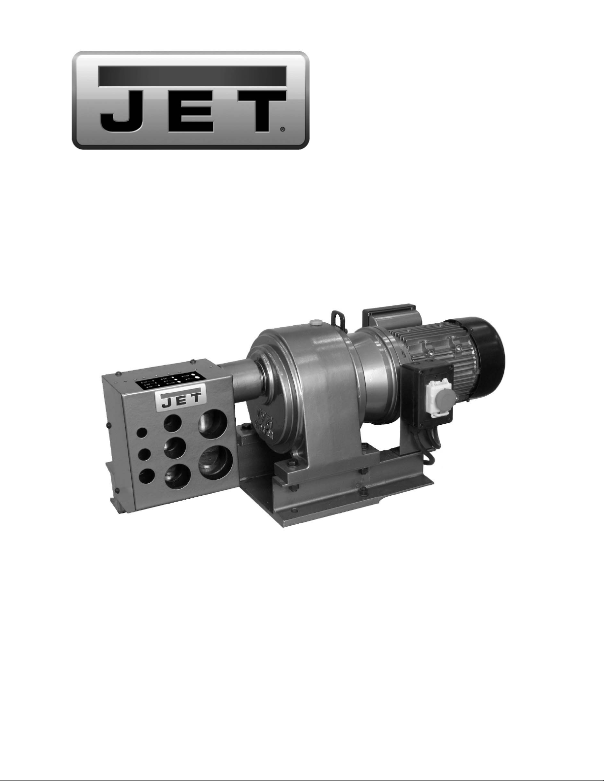
Electric SCH40 Pipe/Tube Notcher
Model ESN-40
JET
427 New Sanford Road
LaVergne, Tennessee 37086 Part No. M-754420
Ph.: 800-274-6848 Edition 1 08/2016
www.jettools.com Copyright © 2016 JET
Page 2

1.0 IMPORTANT SAFETY
INSTRUCTIONS
WARNING – To reduce risk of injury:
1. Read and understand the entire owner’s
manual before attempting assembly or
operation.
2. Read and understand the warnings posted on
the machine and in this manual. Failure to
comply with all of these warnings may cause
serious injury.
3. Replace warning labels if they become
obscured or removed.
4. This pipe notcher is designed and intended for
use by properly trained and experienced
personnel only. If you are not familiar with the
proper and safe operation of a pipe notcher, do
not use it until proper training and knowledge
have been obtained.
5. Do not use this pipe notcher for other than its
intended use. If used for other purposes, JET
disclaims any real or implied warranty and holds
itself harmless from any injury that may result
from that use.
6. Always wear ANSI Z87.1 approved safety
glasses or face shield while using this machine.
(Everyday eyeglasses only have impact
resistant lenses; they are not safety glasses.)
7. Keep hands away from notching holes when
machine is connected to power.
8. Make certain the machine is properly grounded.
9. Before operating the machine, remove tie,
rings, watches, other jewelry, and roll sleeves
up past the elbows. Remove all loose clothing
and confine long hair.
10. Keep the floor around the machine clean and
free of scrap material, oil and grease.
11. Keep machine guards in place at all tim es when
the machine is in use. If removed for
maintenance purposes, use extreme caution
and replace the guards immediately upon
completion of maintenance.
12. Make all machine adjustments or maintenance
with machine unplugged from power source.
13. Use the right tool. Do not force a tool or
attachment to do a job that it was not designed
to do.
14. Make certain the switch is in the OFF position
before connecting the machine to the power
supply.
15. Give your work undivided attention. Looking
around, carrying on a conversation and "horseplay" are careless acts that can result in serious
injury.
16. Keep visitors a safe distance from the work
area. Keep children away.
17. Make your workshop child proof with padlocks,
master switches or by removing starter keys.
18. Maintain a balanced stance at all times so that
you do not fall onto moving parts. Do not
overreach or use excessive force to perform
any machine operation.
19. Use recommended accessories; improper
accessories may be hazardous.
20. Some dust created by power sanding, sawing,
grinding, drilling and other construction
activities contain chemicals known to cause
cancer, birth defects or other reproductive
harm. Some examples of these chemicals are:
• Lead from lead based paint.
• Crystalline silica from bricks, cement and
other masonry products.
• Arsenic and chromium from chemically
treated lumber.
Your risk of exposure varies, depending on how
often you do this type of work. To reduce your
exposure to these chemicals, work in a wellventilated area and work with approved safety
equipment, such as face or dust masks that are
specifically designed to filter out microscopic
particles.
21. Do not operate this machine while under the
influence of drugs, alcohol or any medication.
22. Keep tools sharp and clean for safe and best
performance.
23. Provide for adequate space surrounding work
area and non-glare, overhead lighting.
24. Use only JET factory authorized replacement
parts and accessories; otherwise, the warranty
and guarantee are null and void.
25. Use proper extension cord. Make sure your
extension cord is in good condition. When using
an extension cord, be sure to use one heavy
enough to carry the current your product will
draw. An undersized cord will cause a drop in
line voltage resulting in loss of power and
overheating. Table 1 (sect. 6.2) shows correct
size to use depending on cord length and
nameplate ampere rating. If in doubt, use the
next heavier gage. The smaller the gage
number, the heavier the cord.
2
Page 3

Familiarize yourself with the following safety notices used in this manual:
This means that if precautions are not heeded, it may result in minor injury and/or possible
machine damage.
This means that if precautions are not heeded, it may result in serious, or possibly even fatal,
injury.
SAVE THESE INSTRUCTIONS
2.0 About this manual
This manual is provided by JET, covering the safe operation and maintenance procedures for a JET Model ESN40 Electric Pipe Notcher. This manual contains instructions on installation, safety precautions, general operating
procedures, maintenance instructions and parts breakdown. Your machine has been designed and constructed
to provide consistent, long-term operation if used in accordance with the instructions as set forth in this document.
If there are questions or comments, please contact your local supplier or JET. JET c an also be reached at our
web site: www.jettools.com.
Retain this manual for future reference. If the machine transfers ownership, the manual should accompany it.
Read and understand the entire contents of this manual before attempting assembly or
operation! Failure to comply may cause serious injury!
3.0 Table of contents
Section Page
1.0 IMPORTANT SAFETY INSTRUCTIONS ....................................................................................................... 2
2.0 About this manual .......................................................................................................................................... 3
3.0 Table of contents ............................................................................................................................................ 3
4.0 Specifications ................................................................................................................................................. 4
5.0 Setup .............................................................................................................................................................. 5
6.0 Electrical connections .................................................................................................................................... 5
6.1 GROUNDING INSTRUCTIONS ................................................................................................................. 5
6.2 Extension cords .......................................................................................................................................... 5
7.0 Operation ....................................................................................................................................................... 6
8.0 User-maintenance .......................................................................................................................................... 6
8.1 Additional servicing .................................................................................................................................... 6
9.0 Troubleshooting ESN-40 Pipe Notcher .......................................................................................................... 7
10.0 Replacement Parts ....................................................................................................................................... 7
10.1.1 ESN-40 Pipe Notcher – Exploded View ................................................................................................ 8
10.1.2 ESN-40 Pipe Notcher – Parts List ......................................................................................................... 9
11.0 Electrical Connections for ESN-40 Pipe Notcher ....................................................................................... 10
12.0 Warranty and Service ................................................................................................................................. 11
3
Page 4

4.0 Specifications
Model number ............................................................................................................................................ ESN-40
Stock number .............................................................................................................................................. 754420
Motor and electricals:
Motor type ......................................................................... totally enclosed fan cooled, induction, capacitor start
Horsepower ................................................................................................................................... 2HP (1.5 kW)
Phase .......................................................................................................................................................... single
Voltage ......................................................................................................................................................... 220V
Cycle ............................................................................................................................................................ 60Hz
Listed FLA (full load amps) ........................................................................................................................... 11 A
Running amps (no load) .................................................................................................................................. 5A
Start capacitor ............................................................................................................................. 200μF 250VAC
Run capacitor ................................................................................................................................ 30μF 450VAC
Power transfer ...................................................................................................... direct drive, to eccentric shaft
On/off switch ......................................................................................................................................... magnetic
Power cord .............................................................................................................................................. 14AWG
Power cord length ...................................................................................................................... 7-1/2 ft. (229cm)
Motor cord ............................................................................................................................................... 14AWG
Power plug installed ............................................................................................................................ 15A, 220V
Overload protection .................................................................................... 15A circuit breaker with reset button
Recommended circuit size
Noise emission without load
Capacities:
No. of pipe diameters ......................................................................................................................................... 8
Diameters (SCH 40) ................................................................................. 1/4, 3/8, 1/2, 3/4, 1, 1-1/4, 1-1/2, 2 in.
Maximum wall thickness ........................................................................................................................ 0.133 in.
Notching ................................................................................................................................. 90 deg. fixed angle
Oil capacity .................................................................................................................................................. 2.0 L
Materials:
Main body .............................................................................................................................................. cast iron
Stand ..................................................................................................................................................... cast iron
Notching box ................................................................................................................................................ steel
Dimensions:
Shipping dimensions (LxWxH) .......................................................... 820 x 450 x 480 mm (32-1/4 x 18 x 19 in.)
Overall dimensions (LxWxH) ............................................................ 820 x 380 x 360 mm (32-1/4 x 15 x 14 in.)
Weights:
Net weight (approx..) .................................................................................................................... 98 kg (216 lb.)
Shipping weight (approx..) .......................................................................................................... 112 kg (247 lb.)
1
subject to local/national electrical codes
2
The specified values are emission levels and are not necessarily to be seen as safe operating levels. As workplace
conditions vary, this information is intended to allow the user to make a better estimation of the hazards and risks
involved only.
L= length; W=width; H=height
The specifications in this manual were current at time of publication, but because of our policy of continuous
improvement, JET reserves the right to change specifications at any time and without prior notice, without incurring
obligations.
1
.......................................................................................................................... 15 A
2
.......................................................................................................... below 55 dB
4
Page 5

6.1 GROUNDING INSTRUCTIONS
Read and understand the entire
contents of this manual before attempti ng setup or operation! Failure to comply may cause
serious injury.
5.0 Setup
Remove all crating and check for shipping damage.
Report any damage immediately to your distributor
and shipping agent. Do not discard any shipping
material until Pipe Notcher is set up and operating
properly.
Use hoist, forklift, or similar means to raise Pipe
Notcher using lifting ring on top. Straps and chains
must be properly rated for weight of Notcher.
The Pipe Notcher can be used in horizontal or
vertical position. Mount it to a stable surface with
appropriate fasteners (not provided). Make sure to
leave space around machine for pipe movement
and general maintenance.
Remove any protectant from the machine with a soft
cloth and a cleaner-degreaser or kerosene. Do not
allow solvents to contact painted or plastic areas.
6.0 Electrical connections
Electrical connections must be
made by a qualified electrician in compliance
with all relevant codes. This machine must be
properly grounded to help prevent electrical
shock and possible fatal injury.
This tool must be grounded. In the event of a
malfunction or breakdown, grounding provides a
path of least resistance for electric current to reduce
the risk of electric shock. This tool is equipped with
an electric cord having an equipment-grounding
conductor and a grounding plug. The plug must be
inserted into an appropriate outlet that is properly
installed and grounded in accordance with all local
codes and ordinances.
Improper connection of the
equipment-grounding conductor can r esult in a
risk of electric shock. Check with a qualified
electrician or service person if you are in do ubt
as to whether the outlet is proper ly grounded.
Do not modify the plug pr ovided w ith the tool –
if it will not fit the outlet, have a proper outlet
installed by a qualified electrician.
The conductor with insulation having an outer
surface that is green with or without yellow stripes is
the equipment-grounding conductor. If repair or
replacement of the electric cord or plug is
necessary, do not connect the equipment-grounding
conductor to a live terminal.
Use only 3-wire extension cords that have 3-prong
grounding plugs and 3-pole receptacles that accept
the tool's plug.
Repair or replace damaged or worn cord
immediately.
The ESN-40 Pipe Notcher is ready to run at 230-volt
operation. This tool is intended for use on a circuit
that has an outlet that looks like the one illustrated
in Figure 6-1. The tool is intended for use with a
grounding plug that looks like the plug illustrated in
Figure 6-1. Make sure the tool is connected to an
outlet having the same configuration as the plug. No
adapter is available or should be used with this tool.
If the tool must be reconnected for use on a different
type of electric circuit, the reconnection should be
made by qualified service personnel; and after
reconnection, the tool should comply with all local
codes and ordinances.
Before connecting to power source, be sure switch
is in off position.
It is recommended that the Pipe Notcher be
connected to a dedicated 15 amp circuit with a
circuit breaker or fuse. If connected to a circuit
protected by fuses, use time delay fuse marked “D”.
NOTE: Local codes take precedence over
recommendations.
Figure 6-1: grounding
6.2 Extension cords
The use of extension cords is discouraged; try to
position equipment within reach of the power
source. If an extension cord becomes necessary, be
sure it is heavy enough to carry the current your
product will draw. An undersized cord will cause a
drop in line voltage resulting in loss of power and
overheating.
Table 1 shows recommended size to use depending
on cord length and nameplate ampere rating. If in
doubt, use the next heavier gauge. The smaller the
gauge number, the heavier the cord.
5
Page 6

Ampere
A
Rating
More
Than
00 06 18 16 16 14
06 10 18 16 14 12
10 12 16 16 14 12
12 16 14 12
Not
More
Than
Extension Cord Recommendations
Volts
240 50 100 200 300
AWG
Total length of
cord in feet
Not
Recommended
Table 1
7.0 Operation
Make sure pipe notcher is
properly lubricated before oper ating. Failure to
comply may cause damage to machine.
The Pipe Notcher is shipped with oil in the reduction
box. However, the operator should confirm this
before using the machine! See sect. 8.0.
1. Turn on machine.
2. Clean pipe end of any dirt, chips, burrs, etc.
3. Insert end of pipe into correct hole, determined
by nominal size of schedule 40 pipe (see Figure
7-1). NOTE: Insert only one pipe at a time
into the machine.
4. Continue to lightly press pipe into hole until it
slides farther in and is notched. Pull pipe out.
The scrap will fall to bottom of machine.
5. Remove pipe. It is now read y for saddling and
welding.
8.0 User-maintenance
Disconnect machine from
power supply before performing any
maintenance. Failure to comply may result in
serious injury.
1. It is recommended that the oil be replaced every
2,500 operating hours. Remove set screw to
drain (Figure 8-1).
Capacity - 2.0L. (approximate)
Recommended oil - see Table 2.
2. Remove cover and clean out any lingering chips
or debris around blade area, as needed.
3. Periodically check tightness of all screws.
Figure 8-1: oil drain
mbient
temp.
5℃~20℃
20℃~40℃
40℃~80℃
SHELL
OIL
OMALA 150
OMALA 320
OMALA 460
MOBIL
OIL ISO VG
MOBIL Gear 629 EP 150
MOBIL Gear 632 EP 320
MOBIL Gear 634 EP 460
Figure 7-1:
Sizes represent nominal dimensions
of SCH 40 pipe
Table 2
8.1 Additional servicing
Any additional servicing should be performed by an
authorized JET service center.
6
Page 7

9.0 Troubleshooting ESN-40 Pipe Notcher
Table 3
Symptom Possible Cause Correction *
Motor stalls. Power line overloaded. Correct overload condition.
Insufficient lubrication of blade. Check reservoir; top off as needed.
Oversize material. Make sure material is within thickness
specification of machine.
Blade is jammed. (see following symptom)
Low voltage. Request voltage check from power
company and correct low voltage
condition.
Motor is worn or faulty. Replace motor.
Blade jams, or sticks
during movement.
* WARNING: Some corrections may require a qualified electrician.
Scrap piece stuck in blade area. Remove cover and clean blade area.
Use a soft mallet if needed to dislodge
pieces. Do NOT use a steel-face
hammer
Insufficient lubrication of blade. Check reservoir; top off as needed.
Blade is worn or has burrs. Remove blade and carefully hone, or
replace, if needed.
10.0 Replacement Parts
Replacement parts are listed on the following pages. To order parts or reach our service department, call 1-800274-6848 Monday through Friday, 8:00 a.m. to 5:00 p.m. CST. Having the Model Number and Serial Number of
your machine available when you call will allow us to serve you quickly and accurately.
Non-proprietary parts, such as fasteners, can be found at local hardware stores, or may be ordered from JET.
Some parts are shown for reference only, and may not be available individually.
7
Page 8

10.1.1 ESN-40 Pipe Notcher – Exploded View
8
Page 9

10.1.2 ESN-40 Pipe Notcher – Parts List
Index No. Part No. Description Size Qty
1 ................ ESN40-01 .................. Stand I ..................................................................... ...................................... 1
2 ................ TS-1540081 .............. Hex Nut .................................................................... M12 ............................... 6
3 ................ TS-2360121 .............. Flat
4 ................ ESN40-04 .................. Switch Plate ............................................................. ...................................... 1
5 ................ TS-1505021 .............. Socket Head Cap Screw ......................................... M10x20 ........... .............. 5
6 ................ TS-1505061 .............. Socket Head Cap Screw ......................................... M10x40 ........... .............. 5
7 ................ TS-1505051 .............. Socket Head Cap Screw ......................................... M10x35 ........... .............. 5
8 ................ ESN40-08 .................. Pin............................................................................ ...................................... 2
9 ................ ESN40-09 .................. Pin............................................................................ ...................................... 2
10 .............. ESN40-10 .................. Cover ...................................................................... ...................................... 1
11 .............. ESN40-11 .................. Joint plate I .............................................................. ...................................... 1
12 .............. ESN40-12 .................. Body III..................................................................... ............................. ......... 1
13 .............. ESN40-13 .................. Eccentric shaft ......................................................... ...................................... 1
14 .............. ESN40-14 .................. Body I....................................................................... ............................. ......... 1
15 .............. TS-1492061 .............. Hex Cap Screw ........................................................ M12x60 ..... .................... 2
16 .............. ESN40-16 .................. Blade I...................................................................... ............................. ......... 1
17 .............. ESN40-17 .................. Reduction Box ......................................................... ...................................... 1
18 .............. ESN40-18 .................. Switch ...................................................................... KJD12, 230V ................ 1
19 .............. ESN40-19 .................. Blade III.................................................................... ............................. ......... 1
20 .............. ESN40-20 .................. Body II...................................................................... ............................. ......... 1
21 .............. ESN40-21 .................. Blade II .................................................................... 2x20 mm ....................... 1
22 .............. ESN40-22 .................. Spring ...................................................................... ...................................... 1
23 .............. ESN40-23 .................. Spring ...................................................................... ...................................... 2
24 .............. ESN40-24 .................. Power Cord .............................................................. 14AWG ......................... 1
25 .............. TS-1491081 .............. Hex Cap Screw ........................................................ M10x50 ......................... 4
26 .............. ESN40-26 .................. Key........................................................................... 10x50 mm ..................... 1
27 .............. ESN40-27 .................. Support for Switch ................................................... ...................................... 1
28 .............. TS-1504011 .............. Socket Head Cap Screw ......................................... M8x10 ........................... 2
29 .............. ESN40-29 .................. Box for Magnetic Switch .......................................... ...................................... 1
30 .............. F011287 .................... Phillips Pan Hd Tapping Screw ............................... #8x1/2 (ST4.2x13) ........ 2
31 .............. ESN40-31 .................. Thermal Overload Protector .................................... ...................................... 1
32 .............. ESN40-32 .................. Cord Clamp.............................................................. ...................................... 2
33 .............. ESN40-33 .................. Motor........................................................................ 2HP 230V 1PH ............. 1
33-1 ........... ESN40-33-1 .............. Key (not shown) ...................................................... 8x35 mm ....................... 1
.................. ESN40-33-2 .............. Motor Fan Cover (not shown) .................................. ...................................... 1
.................. ESN40-33-3 .............. Motor Fan (not shown)............................................. ...................................... 1
34 .............. TS-1491031 .............. Hex Cap Screw ........................................................ M10x25 ......................... 4
35 .............. ESN40-35 .................. Junction Box ........................................................... ...................................... 1
36 .............. TS-2284082 .............. Phillips Pan Head Machine Screw ........................... M4x8 ............................. 4
37-1 ........... ESN40-37-1 .............. Starting Capacitor .................................................... 250V 200μf ................... 1
37-2 ........... ESN40-37-2 .............. Running Capacitor ................................................... 450V 30
38 .............. ESN40-38 .................. Junction Box Cover.................................................. ...................................... 1
39 .............. ESN40-39 .................. Self-Tapping Screw ................................................. ST4.2x20 ...................... 4
40 .............. ESN40-40 .................. Oil Fill Plug .............................................................. ...................................... 1
41 .............. ESN40-41 .................. Lifting Ring ............................................................... ...................................... 1
42 .............. TS-1503041 .............. Socket Head Cap Screw ......................................... M6x16 ............. .............. 2
43 .............. TS-2361061 .............. Lock Washer ............................................................ 6 mm ........................... 10
44 .............. TS-2361011 .............. Lock Washer ............................................................ 12 mm ........................... 6
45 .............. TS-2311121 .............. Hex Nut .................................................................... M12 ............................... 1
46 .............. F002101 .................... Lock Washer, Int. Tooth........................................... 12 mm ........................... 1
47 .............. ESN40-47 .................. Drain Plug Screw .................................................... ...................................... 1
48 .............. TS-1534032 .............. Machine Screw, Pan Head, Phillips ......................... M6x10 ........................... 6
49 .............. TS-2361101 .............. Lock Washer ............................................................ 10 mm ........................... 4
50 .............. TS-1534052 .............. Machine Screw, Pan Head, Phillips ......................... M6x16 ........................... 2
51 .............. ESN40-51 .................. Wire ......................................................................... ...................................... 1
52 .............. ESN40-52 ..................
53 .............. ESN40-53 .................. Junction plate .......................................................... ...................................... 1
54 .............. TS-2284082 .............. Machine Screw, Pan Head, Phillips ......................... M4x8 ............................. 4
Washer ............................................................. 12mm .......................... 12
μf ..................... 1
Guard ...................................................................... ...................................... 1
9
Page 10

.................. LM000218 ................. ID Label, ESN-40 (not shown) ................................. ...................................... 1
.................. LM000219 ................. Warning Label (not shown) ...................................... ...................................... 1
.................. LM000230 ................. Label – hole size (not shown) .................................. ...................................... 1
.................. JET-92 ....................... JET Logo (not shown) ............................................. 92x38mm ...................... 1
11.0 Electrical Connections for ESN-40 Pipe Notcher
10
Page 11

12.0 Warranty and Service
JET warrants every product it sells against manufacturers’ defects. If one of our tools needs service or repair, please
contact Technical Service by calling 1-800-274-6846, 8AM to 5PM CST, Monday through Friday.
Warranty Period
The general warranty lasts for the time period specified in the literature included with your product or on the official
JET branded website.
• JET products carry a limited warranty which varies in duration based upon the product. (See chart below)
• Accessories carry a limited warranty of one year from the date of receipt.
• Consumable items are defined as expendable parts or accessories expected to become inoperable within a
reasonable amount of use and are covered by a 90 day limited warranty against manufacturer’s defects.
Who is Covered
This warranty covers only the initial purchaser of the product from the date of delivery.
What is Covered
This warranty covers any defects in workmanship or materials subject to the limitations stated below. This warranty
does not cover failures due directly or indirectly to misuse, abuse, negligence or accidents, normal wear-and-tear,
improper repair, alterations or lack of maintenance. JET woodworking machinery is designed to be used with Wood.
Use of these machines in the processing of metal, plastics, or other materials may void the warranty. The exceptions
are acrylics and other natural items that are made specifically for wood turning.
Warranty Limitations
Woodworking products with a Five Year Warranty that are used for commercial or industrial purposes default to a
Two Year Warranty. Please contact Technical Service at 1-800-274-6846 for further clarification.
How to Get Technical Support
Please contact Technical Service by calling 1-800-274-6846. Please note that you will be asked to provide proof
of initial purchase when calling. If a product requires further inspection, the Technical Service representative will
explain and assist with any additional action needed. JET has Authorized Service Centers located throughout the
United States. For the name of an Authorized Service Center in your area call 1-800-274-6846 or use the Service
Center Locator on the JET website.
More Information
JET is constantly adding new products. For complete, up-to-date product information, check with your local distributor
or visit the JET website.
How State Law Applies
This warranty gives you specific legal rights, subject to applicable state law.
Limitations on This Warranty
JET LIMITS ALL IMPLIED WARRANTIES TO THE PERIOD OF THE LIMITED WARRANTY FOR EACH PRODUCT.
EXCEPT AS STATED HEREIN, ANY IMPLIED WARRANTIES OF MERCHANTABILITY AND FITNESS FOR A
PARTICULAR PURPOSE ARE EXCLUDED. SOME STATES DO NOT ALLOW LIMITATIONS ON HOW LONG AN
IMPLIED WARRANTY LASTS, SO THE ABOVE LIMITATION MAY NOT APPLY TO YOU.
JET SHALL IN NO EVENT BE LIABLE FOR DEATH, INJURIES TO PERSONS OR PROPERTY, OR FOR
INCIDENTAL, CONTINGENT, SPECIAL, OR CONSEQUENTIAL DAMAGES ARISING FROM THE USE OF OUR
PRODUCTS. SOME STATES DO NOT ALLOW THE EXCLUSION OR LIMITATION OF INCIDENTAL OR
CONSEQUENTIAL DAMAGES, SO THE ABOVE LIMITATION OR EXCLUSION MAY NOT APPLY TO YOU.
JET sells through distributors only. The specifications listed in JET printed materials and on official JET website are
given as general information and are not binding. JET reserves the right to effect at any time, without prior notice,
those alterations to parts, fittings, and accessory equipment which they may deem necessary for any reason
whatsoever. JET
Product Listing with Warranty Period
90 Days – Parts; Consumable items
1 Year – Motors; Machine Accessories
2 Year – Metalworking Machinery; Electric Hoists, Electric Hoist Accessories; Woodworking Machinery used
for industrial or commercial purposes
5 Year – Woodworking Machinery
Limited Lifetime – JET Parallel clamps; VOLT Series Electric Hoists; Manual Hoists; Manual Hoist
Accessories; Shop Tools; Warehouse & Dock products; Hand Tools; Air Tools
NOTE: JET is a division of JPW Industries, Inc. References in this document to JET also apply to JPW Industries,
Inc., or any of its successors in interest to the JET brand.
®
branded products are not sold in Canada by JPW Industries, Inc.
11
Page 12

427 New Sanford Road
LaVergne, Tennessee 37086
Phone: 800-274-6848
www.jettools.com
12
 Loading...