

Page 1
Operating Instructions and Parts Manual
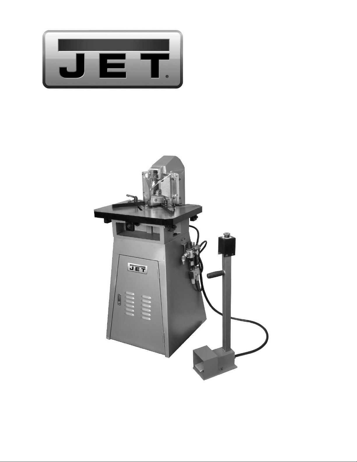
Pneumatic Sheet Metal Notcher
Model PMN-11
JET
427 New Sanford Road
LaVergne, Tennessee 37086 Part No. M-754405
Ph.: 800-274-6848 Edition 2 11/2016
www.jettools.com Copyright © 2016 JET
Page 2

1.0 IMPORTANT SAFETY
INSTRUCTIONS
WARNING – To reduce risk of injury:
1. Read and understand the entire owner’s
manual before attempting assembly or
operation.
2. Read and understand the warnings posted on
the machine and in this manual. Failure to
comply with all of these warnings may cause
serious injury.
3. Replace warning labels if they become
obscured or removed.
4. This pneumatic sheet metal notcher is designed
and intended for use by properly trained and
experienced personnel only. If you are not
familiar with the proper and safe operation of a
sheet metal notcher, do not use it until proper
training and knowledge have been obtained.
5. Do not use this sheet metal notcher for other
than its intended use. If used for other
purposes, JET disclaims any real or implied
warranty and holds itself harmless from any
injury that may result from that use.
6. Always wear ANSI Z87.1 approved safety
glasses or face shield while using this machine.
(Everyday eyeglasses only have impact
resistant lenses; they are not safety glasses.)
7. Wear ear protectors (plugs or muffs) if noise
exceeds safe levels.
8. Before operating the machine, remove tie,
rings, watches, other jewelry, and roll sleeves
up past the elbows. Do not wear loose clothing.
Confine long hair.
9. Keep the f loor around the machine clean and
free of scrap material, oil and grease.
10. Keep machine guards in place at all tim es when
the machine is in use. If removed for
maintenance purposes, use extreme caution
and replace the guards immediately upon
completion of maintenance.
11. Check damaged parts. Before further use of the
machine, a guard or other part that is damaged
should be carefully checked to determine that it
will operate properly and perform its intended
function. Check for alignment of moving parts,
binding of moving parts, breakage of parts,
mounting and any other conditions that may
affect its operation. A guard or other part that is
damaged should be properly repaired or
replaced.
12. Make all machine adjustments or maintenance
with machine unplugged from power source.
13. Use the right tool. Do not force a tool or
attachment to do a job that it was not designed
to do.
14. Make certain the switch is in the OFF position
before connecting the machine to the air or
power supply.
15. Remove adjusting keys and wrenches. Form a
habit of checking to see that keys and adjusting
wrenches are removed from the machine
before turning it on.
16. Give your work undivided attention. Looking
around, carrying on a conversation and "horseplay" are careless acts that can result in serious
injury.
17. Keep visitors a safe distance from the work
area. Keep children away.
18. Make your workshop child proof with padlocks,
master switches or by removing starter keys.
19. Do not overreach. Failure to maintain proper
working position can cause you to fall into the
machine or allow clothing to get caught, pulling
you into the machine.
20. Keep the floor around the machine clean and
free of scrap material, oil and grease.
21. Use recommended accessories; improper
accessories may be hazardous.
22. CALIFORNIA PROPOSITION 65 WARNING:
This product contains chemicals known to the
State of California to cause cancer, or birth
defects or other reproductive harm.
23. This product, when used for welding, cutting, or
working with metal, produces fumes, gases, or
dusts which contain chemicals known to the
State of California to cause birth defects and, in
some cases, cancer. (California Health and
Safety Code Section 25249.5 et seq.)
24. Do not operate this machine while under the
influence of drugs, alcohol or any medication.
25. Keep tools sharp and clean for safe and best
performance.
26. Keep hands away from the blade area during
operation.
27. Provide for adequate space surrounding work
area and non-glare, overhead lighting.
28. Don't use in dangerous environment. Don't use
power tools in damp or wet locations, or expose
them to rain.
29. Do not stand on the machine. Serious injury
could occur if the machine tips over.
2
Page 3

30. Never leave the machine running unattended.
Disconnect machine from air supply before
leaving the area.
31. Do not step on the foot pedal control before or
during connection of air supply.
32. Use only JET factory authorized replacement
parts and accessories; otherwise, the warranty
and guarantee are null and void.
33. Do not attempt to cut material greater than the
listed capacity of the notcher.
34. Do not use combustible gases, carbon diox ide,
oxygen or any bottled gas as an air source for
Familiarize yourself with the following safety notices used in this manual:
This means that if precautions are not heeded, it may result in minor injury and/or possible
machine damage.
This means that if precautions are not heeded, it may result in serious, or possibly even fatal,
injury.
the tool. These can present risk of explosion
and serious injury.
35. Compressed air can be harmful if directed
toward sensitive areas of the body, and may
propel small particles caught in the air stream.
Exercise proper caution.
36. Shut off air supply and discharge any residual
pressure from machine before removing hose,
making adjustments, changing accessories, or
storing.
SAVE THESE INSTRUCTIONS
2.0 About this manual
This manual is provided by JET, covering the safe operation and maintenance procedures for a JET Model PMN11 Pneumatic Sheet Metal Notcher. This manual contains instructions on installation, safety precautions, general
operating procedures, maintenance instructions and parts breakdown. Your machine has been designed and
constructed to provide consistent, long-term operation if used in accordance with the instructions as set forth in
this document.
If there are questions or comments, please contact your local supplier or JET. JET c an also be reached at our
web site: www.jettools.com.
Retain this manual for future reference. If the machine transfers ownership, the manual should accompany it.
Read and understand the entire contents of this manual before attempting assembly or
operation! Failure to comply may cause serious injury!
Register your product online -
http://www.jettools.com/us/en/service-and-support/warranty/registration/
3
Page 4

3.0 Table of contents
Section Page
1.0 IMPORTANT SAFETY INSTRUCTIONS ....................................................................................................... 2
2.0 About this manual .......................................................................................................................................... 3
3.0 Table of contents ............................................................................................................................................ 4
4.0 Specifications ................................................................................................................................................. 5
5.0 Setup and assembly ....................................................................................................................................... 6
5.1 Shipping contents ....................................................................................................................................... 6
5.2 Location and cleanup ................................................................................................................................. 6
5.3 Air settings and lubrication ......................................................................................................................... 6
6.0 Operation ....................................................................................................................................................... 7
6.1 Controls ...................................................................................................................................................... 7
6.2 General operating procedure ..................................................................................................................... 7
7.0 Adjustments ................................................................................................................................................... 7
7.1 Blade gap tolerance ................................................................................................................................... 7
8.0 User-maintenance .......................................................................................................................................... 8
8.1 Additional servicing .................................................................................................................................... 8
9.0 Troubleshooting PMN-11 Pneumatic Notcher ................................................................................................ 9
10.0 Replacement Parts ....................................................................................................................................... 9
10.1.1 PMN-11 Pneumatic Notcher – Exploded View .................................................................................... 10
10.1.2 PMN-11 Pneumatic Notcher – Parts List ............................................................................................. 11
11.0 Pneumatic diagram for PMN-11 Notcher ................................................................................................... 13
12.0 Warranty and Service ................................................................................................................................. 14
4
Page 5

4.0 Specifications
Model number ............................................................................................................................................ PMN-11
Stock number .............................................................................................................................................. 754405
Air supply:
Working pressure ................................................................................................................... 115 PSI (8 kg/cm2)
Average air consumption ................................................................................................................. 154.6 CFM
Air intake connector ........................................................................................................................... 3/8 in. NPT
Air system lubrication required ................................................................. lubricator bowl, ISO VG32 (SAE #10)
Foot switch ........................................................................................................... satellite foot pedal with E-stop
Foot switch cable length (approx..) .......................................................................................... 4-1/2 ft. (137 cm)
Capacities:
Blade length ............................................................................................................ 130 x 130 mm (5.2 x 5.2 in.)
Strokes per minute ........................................................................................................................................... 50
Working force .......................................................................................................................................... 2.2 tons
Maximum cutting thickness (mild steel) ..................... 2mm/14 ga. (R=60 kg/mm
Notching angle ............................................................................................................................ 90-degree fixed
Workpiece positioning ....................................................................................................... up to 45-deg. L and R
Maximum blade travel ................................................................................................................. 25mm (0.98 in.)
Main mate ri a l s :
Cabinet ........................................................................................................................... sheet metal; steel plate
Cutting head ......................................................................................................................................... cast steel
Blades .......................................................................................................................................... hardened steel
Dimensions:
Table size ................................................................................................................. 460 x 600 mm (18 x 24 in.)
Table height from floor .......................................................................................................... 946 mm (37-1/4 in.)
Shipping dimensions (LxWxH) ............................................................ 754 x 706 x 1366 mm (30 x 28 x 53.8 in.)
Overall dimensions (LxWxH) .............................................................. 660 x 600 x 1260 mm (26 x 23.6 x 50 in.)
Weights:
Net ........................................................................................................................................... 160 kg (352.7 lb)
Shipping .................................................................................................................................... 188 kg (414.5 lb)
L= length; W=width; H=height
The specifications in this manual were current at time of publication, but because of our policy of continuous
improvement, JET reserves the right to change specifications at any time and without prior notice, without incurring
obligations.
2
); 3mm/11 ga. (R=42 kg/mm2)
Read and understand the entire contents of this manual before attempting set-up or
operation! Failure to comply may cause serious injury.
5
Page 6

Read and understand the entire
contents of this manual before attempti ng setup or operation! Failure to comply may cause
serious injury.
5.0 Setup and assembly
Open shipping container and check for shipping
damage. Report any damage immediately to your
distributor and shipping agent. Do not discard any
shipping material until machine is assembled and
running properly.
Compare the contents of your container with the
following parts list to make sure all parts are intact.
Missing parts, if any, should be reported to your
distributor. Read the instruction manual thoroughly
for assembly, maintenance and safety instructions.
5.1 Shipping contents
1 Pneumatic Notcher
1 Angle gauge
1 0.3mm feeler gauge
1 14mm combination wrench
1 5mm hex key
1 Operating Instructions and Parts Manual
1 Warranty Card
screws or other appropriate fasteners
through two holes in base (inside cabinet).
4. Exposed metal surfaces have been given a
protective coating. Remove this with a soft cloth
and a cleaner-degreaser. Do not use gasoline,
paint thinner, acetone, etc., as these may
damage painted surfaces. Do not use an
abrasive pad, as it may scratch polished
surfaces.
5.3 Air settings and lubrication
NOTE: Lubricator bowl (H, Figure 5-2) is not
supplied with oil. Fill bowl to indicator line before
operating notcher.
1. Make sure air c ompressor supplies clean, dry
air at correct CFM for the machine. Blow out air
supply line to remove any dirt or moisture, and
connect hose to fitting (A, Figure 5-2) using a
quick-connect coupling. Hose should be just
long enough to serve the working area.
Excessive hose length may cause pressure
drop.
Excess air pressure and/or
unclean air will reduce the machine’s
service life and may create a hazardous
situation.
5.2 Location and cleanup
1. Remove any fasteners holding machine to
pallet.
2. Use forklift or hoist with straps to carefully move
machine off pallet and into position. Lifting
equipment must be properly rated for weight
of machine. Position forks or straps below
table as shown in Figure 5-1.
Figure 5-1: lifting the machine
3. Position notcher so there is enough room on all
sides for general maintenance and feeding of
materials. Level the machine; use shims if
needed.
2. The sliding valve (B) is used to turn air flow on
and off. ON: slide toward regulator, OFF: slide
away from regulator.
3. Air pressure has been pre-set for 115 psi (8
4. Adjust oil flow by turning adjustment knob (E).
2
). If adjustment is needed, turn on air and
kg/cm
pull up on pressure regulator (C) and rotate.
Check pressure gauge (D) to confirm setting,
then push regulator down to lock setting. Do
not exceed 140 psi air pressure.
Clockwise decreases oil flow, counterclockwise
increases. A setting of 1 drop per every 5 cycles
is sufficient for regular operation.
Figure 5-2: air adjustments
If there is any tendency for
machine to move or slide during opera tion,
it must be anchored to floor using lag
6
Page 7

6.0 Operation
6.1 Controls
Press foot pedal to activate machine. Cutting head
will descend and remain in down position until foot
pedal is released.
An Emergency Stop switch (E-stop) is located atop
the foot pedal post; push for immediate shut-down
of machine. To restart, rotate E-stop clockwise until
it disengages.
6.2 General operating procedure
1. Use scales (A, Figure 6-1) to help determine
notching size.
2. Place angle indicator (B) against fence to help
set angle for workpiece.
3. Position fences (C) to secure workpiece in
place, and tighten handles.
4. Press foot pedal to operate. Cut pieces will drop
into tray inside cabinet.
Falling sheet metal piece s
can cause foot injury. Use appropriate
footwear when operating this machine.
2. Turn off air with sliding valve (see B, Figure 5-
2) and bleed residual air from system (see G,
Figure 5-2).
3. Release foot pedal.
4. DISCONNECT air supply from machine.
5. Remove screws (D, Figure 8-1) and head guard
(E).
6. Use feeler gauge to measure gap between
upper and lower blades (Figure 8-2).
7. Make adjustments using hex nuts beneath
table. Turn (F) to raise or lower blade, turn ( G)
to move in and out. Feeler gauge should be
snug but can still be smoothly removed.
8. Make sure blades are flush against each other
at the corners. See Figure 8-3.
9. Reinstall head guard and tighten screws.
Figure 6-1
7.0 Adjustments
Disconnect machine from air
supply before working with or near the blades. If
head guard is removed for adjustments, reinstall
guard before operating machine. Failure to
comply may cause serious injury.
7.1 Blade gap tolerance
The notcher is pre-set for 3mm (12 ga.) workpiece
thickness, with 0.3mm blade gap tolerance. A
0.3mm feeler gauge is provided to assist in checking
this measurement. If notching workpieces 2mm
(14ga.) or thinner, adjust blade gap to 0.1mm, as
follows.
1. Press foot pedal to lower notching head;
continue pressing it.
Figure 8-1
Figure 8-2: gap adjustment
7
Page 8

Figure 8-3
8.0 User-maintenance
Disconnect machine from air
supply before performing any maintenance. If
head guard is removed for servicing, reinstall
guard before operating machine. Failure to
comply may cause serious injury.
1. Periodically insert oil into two fittings (A, Figure
9-1)
2. Periodically apply oil to pivot areas of
connection plate (B).
3. Drain water from air compress or tank daily, as
well as any condensation from air lines. Change
filters on the air system on a regular basis.
4. Periodically check filter/regulator bowl (F,
Figure 5-2) for fluids or sediment accumulation,
and empty if needed. Bowl should be emptied
before fluid reaches maximum drain level as
indicated on bowl. To remove a bowl, shut off
air supply and push pin (G, Figure 5-2) to bleed
excess air. Then press tab, rotate bowl to the
left, and pull bowl down. Reverse procedure to
reinstall bowl. Make sure bowl is locked in
position before applying air to the system!
5. Maintain oil level in lubricator bowl (H, Figure 5-
2); top off as needed with ISO 32 (SAE 10) nondetergent, non-additive oil. Remove screw (J,
Figure 5-2) with screwdriver to fill.
6. Keep table and T-slots clean and free of rust.
Periodically apply a light coat of SAE 30 oil or
equivalent to exposed metal surfaces, such as
table, fences and blades.
7. Check air connections; replace components if
leakage is found.
8. Keep blade area free of deposits or shavings,
which can impede cut quality and hasten blade
wear.
9. Maintain sharp blades. If they become dull,
remove and re-sharpen.
Figure 9-1
8.1 Additional servicing
Any additional servicing should be performed by
authorized service personnel.
8
Page 9

9.0 Troubleshooting PMN-11 Pneumatic Notcher
Table 2
Symptom Possible Cause Correction
Machine will not start.
Loss of power; erratic
action
Machine appears to
labor during cutting.
Edges of cut are rough
or rolled.
Poor cut quality.
Air valve closed or obstructed. Open valve; clear any obstructions.
Foot pedal malfunction. Inspect and replace if needed.
Verify compressor has proper CFM
rating for tool.
Low air pressure.
Moisture or obstruction in air hose. Air supply must be clean and dry. Clean
Machine capacity exceeded. Use materials within rated capacity.
Improper lubrication. Follow lubricating guidelines.
Blade gap incorrect. Adjust blade gap.
Insufficient workpiece material on both
sides of blade.
Machine capacity exceeded. Use materials within rated capacity.
Blades dry; improper lubrication. Follow lubricating guidelines.
Blades dull or damaged. Resharpen or replace blades.
Blades are loose. Check all blades for tightness.
Check regulator setting; set air pressure
to 115 psi.
Check for loose connections.
out air hose and remove any kinks or
bends.
Make sure workpiece length on both
sides of blades is approximately 8 times
workpiece thickness.
10.0 Replacement Parts
Replacement parts are listed on the following pages. To order parts or reach our service department, call 1-800274-6848 Monday through Friday, 8:00 a.m. to 5:00 p.m. CST. Having the Model Number and Serial Number of
your machine available when you call will allow us to serve you quickly and accurately.
Non-proprietary parts, such as fasteners, can be found at local hardware stores, or may be ordered from JET.
Some parts are shown for reference only, and may not be available individually.
9
Page 10

10.1.1 PMN-11 Pneumatic Notcher – Exploded View
10
Page 11

10.1.2 PMN-11 Pneumatic Notcher – Parts List
Index No. Part No. Description Size Qty
1 ................ PMN11-1 ................... Cabinet .................................................................... ...................................... 1
2 ................ PMN11-2 ................... Air Control Unit ........................................................ ...................................... 1
2-1 ............. PMN11-2-1 ................ Pressure Regulator .................................................. ...................................... 1
2-2 ............. PMN11-2-2 ................ Pressure Gauge ...................................................... ...................................... 1
2-3 ............. PMN11-2-3 ................ Adaptor Set .............................................................. ...................................... 1
3 ................ TS-1540041 .............. Hex Nut .................................................................... FULL M6 ....................... 2
4 ................ TS-1534042 .............. Mach Screw, Pan HD, Phillips ................................. M6x12 ........................... 4
5 ................ PMN11-5 ................... Air Control Bracket................................................... ...................................... 1
6 ................ TS-0680061 .............. Flat Washer ............................................................. M 12 ............................... 4
7 ................ TS-1492041 .............. Hex Cap Screw ........................................................ M12x40 ... ..................... 4
8 ................ PMN11-8 ................... Hex Cap Screw ........................................................ M16 ............................... 2
9 ................ TS-2311161 .............. Hex Nut .................................................................... FULL M16 ..................... 2
10 .............. F010413 .................... Socket Set Screw .................................................... M8x30 ........................... 2
11 .............. TS-1540061 .............. Hex Nut .................................................................... FULL M8 ....................... 2
12 .............. PMN11-12 ................. Head Weldment ....................................................... ...................................... 1
13 .............. PMN11-13 ................. Air Cylinder .............................................................. ...................................... 1
14 .............. PMN11-14 ................. Pin (Short)................................................................ ...................................... 1
15 .............. PMN11-15 ................. Connection Plate ..................................................... ...................................... 1
16 .............. PMN11-16 ................. Pin............................................................................ ...................................... 1
17 .............. PMN11-17 ................. C-Ring...................................................................... S-14 .............................. 4
18 .............. PMN11-18 ................. Pin............................................................................ ...................................... 1
19 .............. PMN11-19 ................. Link Bar.................................................................... ...................................... 1
20 .............. PMN11-20 ................. Upper Left Blade ...................................................... ...................................... 1
21 .............. PMN11-21 ................. Thin Socket HD Cap Screw ..................................... M8x20 ........................... 8
22 .............. PMN11-22 ................. Upper Right Blade ................................................... ...................................... 1
23 .............. PMN11-23 ................. Cutting Head Weldment .......................................... ...................................... 1
24 .............. PMN11-24 ................. Block ........................................................................ ...................................... 2
25 .............. TS-1550061 .............. Flat Washer ............................................................. M 8 ............................... 10
26 .............. PMN11-26 ................. Spacer Plate ............................................................ ...................................... 2
27 .............. TS-1540081 .............. Hex Nut .................................................................... FULL M12 ..................... 7
28 .............. TS-1504071 .............. Socket HD Cap Screw ............................................. M8x35 ........... .............. 10
29 .............. PMN11-29 ................. Full Thread Bolt ....................................................... M12x120 ....................... 1
30 .............. TS-2244202 .............. Socket HD Button Screw ......................................... M4X20 .......................... 4
31 .............. TS-2360121 .............. Flat Washer ............................................................. M 12 ............................... 2
32 .............. PMN11-32 ................. Table ........................................................................ ...................................... 1
33 .............. F010434 .................... Socket Set Screw .................................................... M12x60 ......................... 4
34 .............. PMN11-34 ................. T-Type Key .............................................................. ...................................... 2
35 .............. PMN11-35 ................. Connection Pin ........................................................ ...................................... 2
36 .............. PMN11-36 ................. Right Fence ............................................................. ...................................... 1
37 .............. TS-2331101 .............. Cap Nut.................................................................... M10 ... ............................ 2
38 .............. PMN11-38 ................. Fixing Pin ................................................................. ...................................... 2
39 .............. TS-0680041 .............. Flat Washer ............................................................. 3/8 ................................. 4
40 .............. PMN11-40 ................. Left Fence ................................................................ ...................................... 1
41 .............. PMN11-41 ................. Lower Right Blade ................................................... ...................................... 1
42 .............. PMN11-42 ................. Lower Left Blade ...................................................... ...................................... 1
43 .............. PMN11-43 ................. Right Scale .............................................................. ...................................... 1
43-1 ........... PMN11-43-1 .............. Left Scale ................................................................. ...................................... 1
.................. PMN11-AG ................ Angle Guide Assembly (#44-50) .............................. ...................................... 1
44 .............. PMN11-44 ................. Knob ........................................................................ M6x10 ........................... 1
45 .............. TS-0680021 .............. Flat Washer ............................................................. 1/4 ................................. 1
46 .............. PMN11-46 ................. Guide Bar................................................................. ...................................... 1
47 .............. PMN11-47 ................. Angle Indicator ......................................................... ...................................... 1
48 .............. PMN11-48 ................. Knob ........................................................................ ...................................... 1
49 .............. TS-2284082 .............. Mach Screw, Pan HD, Phillips ................................. M4x8 ............................. 1
50 .............. PMN11-50 ................. Flat Washer ............................................................. M4 ................................. 1
51 .............. PMN11-51 ................. Cover Plate .............................................................. ...................................... 1
52 .............. PMN11-52 ................. Air Cylinder Cover.................................................... ...................................... 1
53 .............. PMN11-53 ................. Guard ....................................................................... ...................................... 1
54 .............. TS-2244102 .............. Socket HD Button Screw ......................................... M4X10 .......................... 2
55 .............. PMN11-55 ................. Multipurpose Valve ................................................. ...................................... 1
11
Page 12

Index No. Part No. Description Size Qty
56 .............. TS-1541031 .............. Hex Nut, Nylon Lock ................................................ M8 ................................. 1
57 .............. TS-1523021 .............. Socket Set Screw .................................................... M6x8 ............................. 1
58 .............. PMN11-58 ................. Hex Head Bolt.......................................................... M8 ................................. 1
59 .............. PMN11-59 ................. Hose Connector ....................................................... ...................................... 1
60 .............. PMN11-60 ................. Hose Elbow Connector ............................................ 90 deg. .......................... 1
61 .............. .................................. Hose A (RE: 63-1) ................................................... ø9 x Ø12 x 820 mm ...... 1
62 .............. .................................. Hose B (RE: 63-1) ................................................... ø9 x Ø12 x 620 mm ...... 1
63 .............. .................................. Hose C (RE: 63-1) ................................................... ø9 x Ø12 x 620 mm ...... 1
63-1 ........... PMN11-63-1 .............. Hose * ...................................................................... ø9 x Ø12 ... (cut to length)
65 .............. PMN11-65 ................. Foot Pedal Assembly ............................................... ...................................... 1
66 .............. F001213 .................... Mach Screw, Pan HD, Phillips ................................. M5x40 ........................... 2
67 .............. PMN11-67 ................. Noise Reducer ......................................................... ...................................... 2
68 .............. EMN9-90 ................... Door Latch ............................................................... ...................................... 1
69 .............. TS-2361121 .............. Lock Washer ............................................................ M12 ............................. 10
70 .............. PMN11-70 ................. Hose D ..................................................................... 230MM .......................... 1
71 .............. PMN11-71 ................. Hose ........................................................................ 3/8x1660MM ................. 1
72 .............. PMN11-72 ................. PU Hose A ............................................................... 1985MM ........................ 1
73 .............. PMN11-73 ................. PU Hose B ............................................................... 2485MM ........................ 1
74 .............. TS-1504021 .............. Socket HD Cap Screw ............................................. M8x12 ........... ................ 2
75 .............. PMN11-75 ................. Flat Washer ............................................................. 5/16x23x2 ..................... 4
76 .............. PMN11-76 ................. Mach Screw, Pan HD, Phillips ................................. 5/16x1 ........................... 2
77 .............. PMN11-77 ................. Shipping Bracket ..................................................... ...................................... 2
78 .............. TS-2245102 .............. Socket HD Button Screw ......................................... M5X10 ......................... 2
79 .............. EMN9-17 ................... Handle ..................................................................... M10 ............................... 2
80 .............. PMN11-80 ................. Cabinet Door............................................................ ...................................... 1
81 .............. PMN11-81 ................. Foot Pedal Plate ...................................................... ...................................... 1
82 .............. PMN11-82 ................. Post.......................................................................... ...................................... 1
83 .............. PMN11-83 ................. Plastic Grip .............................................................. ...................................... 1
84 .............. F001214 .................... Mach Screw, Pan HD, Phillips ................................. M6*8 ............................. 2
85 .............. PMN11-85 ................. Emergency Stop Switch Box ................................... ...................................... 1
86 .............. PMN11-86 ................. Emergency Stop Switch........................................... ...................................... 1
87 .............. TS-2246082 .............. Socket HD Button Screw ......................................... M6x8 ............. ................ 4
88 .............. F001208 .................... Mach Screw, Pan HD, Phillips ................................. M5x8 ............................. 2
89 .............. PMN11-89 ................. Hose ........................................................................ 3/8x220MM ................... 1
90 .............. PMN11-90 ................. PU Hose C ............................................................... 940MM .......................... 1
.................. JET-165 ..................... JET Logo (not shown) ............................................. 165x68mm .................... 1
.................. LM000225 ................. ID Label, PMN-11 (not shown) ................................ ...................................... 1
.................. LM000223 ................. Warning Label (not shown) ...................................... ...................................... 1
* specify needed length when ordering
12
Page 13

11.0 Pneumatic diagram for PMN-11 Notcher
Ref. Description
1 Air drain valve switch
2 Condensate drain filter
3 Pressure reducer valve
4 Lubricator
5 Noise reducer
6 Foot control pedal with lock
7 Multipurpose valve
8 Air cylinder
9 Emergency stop
13
Page 14

12.0 Warranty and Service
JET warrants every product it sells against manufacturers’ defects. If one of our tools needs service or repair, please
contact Technical Service by calling 1-800-274-6846, 8AM to 5PM CST, Monday through Friday.
Warranty Period
The general warranty lasts for the time period specified in the literature included with your product or on the official
JET branded website.
• JET products carry a limited warranty which varies in duration based upon the product. (See chart below)
• Accessories carry a limited warranty of one year from the date of receipt.
• Consumable items are defined as expendable parts or accessories expected to become inoperable within a
reasonable amount of use and are covered by a 90 day limited warranty against manufacturer’s defects.
Who is Covered
This warranty covers only the initial purchaser of the product from the date of delivery.
What is Covered
This warranty covers any defects in workmanship or materials subject to the limitations stated below. This warranty
does not cover failures due directly or indirectly to misuse, abuse, negligence or accidents, normal wear-and-tear,
improper repair, alterations or lack of maintenance. JET woodworking machinery is designed to be used with Wood.
Use of these machines in the processing of metal, plastics, or other materials may void the warranty. The exceptions
are acrylics and other natural items that are made specifically for wood turning.
Warranty Limitations
Woodworking products with a Five Year Warranty that are used for commercial or industrial purposes default to a
Two Year Warranty. Please contact Technical Service at 1-800-274-6846 for further clarification.
How to Get Technical Support
Please contact Technical Service by calling 1-800-274-6846. Please note that you will be asked to provide proof
of initial purchase when calling. If a product requires further inspection, the Technical Service representative will
explain and assist with any additional action needed. JET has Authorized Service Centers located throughout the
United States. For the name of an Authorized Service Center in your area call 1-800-274-6846 or use the Service
Center Locator on the JET website.
More Information
JET is constantly adding new products. For complete, up-to-date product information, check with your local distributor
or visit the JET website.
How State Law Applies
This warranty gives you specific legal rights, subject to applicable state law.
Limitations on This Warranty
JET LIMITS ALL IMPLIED WARRANTIES TO THE PERIOD OF THE LIMITED WARRANTY FOR EACH PRODUCT.
EXCEPT AS STATED HEREIN, ANY IMPLIED WARRANTIES OF MERCHANTABILITY AND FITNESS FOR A
PARTICULAR PURPOSE ARE EXCLUDED. SOME STATES DO NOT ALLOW LIMITATIONS ON HOW LONG AN
IMPLIED WARRANTY LASTS, SO THE ABOVE LIMITATION MAY NOT APPLY TO YOU.
JET SHALL IN NO EVENT BE LIABLE FOR DEATH, INJURIES TO PERSONS OR PROPERTY, OR FOR
INCIDENTAL, CONTINGENT, SPECIAL, OR CONSEQUENTIAL DAMAGES ARISING FROM THE USE OF OUR
PRODUCTS. SOME STATES DO NOT ALLOW THE EXCLUSION OR LIMITATION OF INCIDENTAL OR
CONSEQUENTIAL DAMAGES, SO THE ABOVE LIMITATION OR EXCLUSION MAY NOT APPLY TO YOU.
JET sells through distributors only. The specifications listed in JET printed materials and on official JET website are
given as general information and are not binding. JET reserves the right to effect at any time, without prior notice,
those alterations to parts, fittings, and accessory equipment which they may deem necessary for any reason
whatsoever. JET
Product Listing with Warranty Period
90 Days – Parts; Consumable items
1 Year – Motors; Machine Accessories
2 Year – Metalworking Machinery; Electric Hoists, Electric Hoist Accessories; Woodworking Machinery used
for industrial or commercial purposes
5 Year – Woodworking Machinery
Limited Lifetime – JET Parallel clamps; VOLT Series Electric Hoists; Manual Hoists; Manual Hoist
Accessories; Shop Tools; Warehouse & Dock products; Hand Tools; Air Tools
NOTE: JET is a division of JPW Industries, Inc. References in this document to JET also apply to JPW Industries,
Inc., or any of its successors in interest to the JET brand.
®
branded products are not sold in Canada by JPW Industries, Inc.
14
Page 15

This page intentionally left blank.
15
Page 16

427 New Sanford Road
LaVergne, Tennessee 37086
Phone: 800-274-6848
www.jettools.com
16
 Loading...