

Page 1

This .pdf document is bookmarked
Operating Instructions and Parts Manual
Oscillating Spindle Sander
Model JOSS-S
JET
427 New Sanford Road
LaVergne, Tennessee 37086 Part No. M-723950
Ph.: 800-274-6848 Revision A 03/2015
www.jettools.com Copyright © 2015 JET
Page 2

1.0 Warranty and service
JET warrants every product it sells against manufacturers’ defects. If one of our tools needs service or repair, please
contact Technical Service by calling 1-800-274-6846, 8AM to 5PM CST, Monday through Friday.
Warranty Period
The general warranty lasts for the time period specified in the literature included with your product or on the official
JET branded website.
• JET products carry a limited warranty which varies in duration based upon the product. (See chart below)
• Accessories carry a limited warranty of one year from the date of receipt.
• Consumable items are defined as expendable parts or accessories expected to become inoperable within a
reasonable amount of use and are covered by a 90 day limited warranty against manufacturer’s defects.
Who is Covered
This warranty covers only the initial purchaser of the product from the date of delivery.
What is Co vered
This warranty covers any defects in workmanship or materials subject to the limitations stated below. This warranty
does not cover failures due directly or indirectly to misuse, abuse, negligence or accidents, normal wear-and-tear,
improper repair, alterations or lack of maintenance. JET woodworking machinery is designed to be used with Wood.
Use o f these ma chines in the pr oces sing of metal, plast ics, or other m aterial s out side recommen ded guidelines may
void the warranty. The exceptions are acrylics and other natural items that are made specifically for wood turning.
Warranty Limitations
Woodworking products with a Five Year Warranty that are used for commercial or industrial purposes default to a
Two Year Warranty. Please contact Technical Service at 1-800-274-6846 for further clarification.
How to Get Technical Support
Please contact Technical Service by calling 1-800-274-6846. Please note that you will be asked to provide pro of
of initia l p u rch a s e whe n calling. If a product requires further inspection, the Technical Service representative will
explain and assist with any additional action needed. JET has Authorized Service Centers located throughout the
United States. For the name of an Authorized Service Center in your area call 1-800-274-6846 or use the Service
Center Locator on the JET website.
More Informa t io n
JET is constantly adding new products. For complete, up-to-date product information, check with your local distributor
or visit the JET website.
How State Law Appli es
This warranty gives you specific legal rights, subject to applicable state law.
Limitations on This Warranty
JET LIMITS ALL IMPLIED WARRANTIES TO THE PERIOD OF THE LIMITED WARRANTY FOR EACH PRODUCT.
EXCEPT AS STATED HEREIN, ANY IMPLIED WARRANTIES OF MERCHANTABILITY AND FITNESS FOR A
PARTICULAR PURPOSE ARE EXCLUDED. SOME STATES DO NOT ALLOW LIMITATIONS ON HOW LONG AN
IMPLIED WARRANTY LASTS, SO THE ABOVE LIMITATION MAY NOT APPLY TO YOU.
JET SHALL IN NO EVENT BE LIABLE FOR DEATH, INJURIES TO PERSONS OR PROPERTY, OR FOR
INCIDENTAL, CONTINGENT, SPECIAL, OR CONSEQUENTIAL DAMAGES ARISING FROM THE USE OF OUR
PRODUCTS. SOME STATES DO NOT ALLOW THE EXCLUSION OR LIMITATION OF INCIDENTAL OR
CONSEQUENTIAL DAMAGES, SO THE ABOVE LIMITATION OR EXCLUSION MAY NOT APPLY TO YOU.
JET sells through distributors only. The specifications listed in JET printed materials and on official JET website are
given as general information and are not binding. JET reserves the right to effect at any time, without prior notice,
those alterations to parts, fittings, and accessory equipment which they may deem necessary for any reason
whatsoever. JET
Product Listing with Warranty Period
90 Days – Parts; Consumable items; Light-Duty Air Tools
1 Year – Motors; Machine Accessories; Heavy-Duty Air Tools; Pro-Duty Air Tools
2 Year – Metalworking Machinery; Electric Hoists, Electric Hoist Accessories; Woodworking Machinery used
for industrial or commercial purposes
5 Year – Woodworking Machinery
Limited Lifetime – JET Parallel clamps; VOLT Series Electric Hoists; Manual Hoists; Manual Hoist
Accessories; Shop Tools; Warehouse & Dock products; Hand Tools
NOTE: JET is a division of JPW Industries, Inc. References in this document to JET also apply to JPW Industries,
Inc., or any of its successors in interest to the JET brand.
®
branded products are not sold in Canada by JPW Industries, Inc.
2
Page 3

2.0 Table of contents
Section Page
1.0 Warranty and service ..................................................................................................................................... 2
2.0 Table of contents ............................................................................................................................................ 3
3.0 Safety warnings .............................................................................................................................................. 4
4.0 About this manual .......................................................................................................................................... 5
5.0 Specifications ................................................................................................................................................. 6
6.0 Setup and assembly ....................................................................................................................................... 7
6.1 Shipping contents ....................................................................................................................................... 7
6.2 Additional tools required ............................................................................................................................. 7
6.3 Unpacking and cleanup .............................................................................................................................. 7
6.4 Removal from pallet ................................................................................................................................... 8
6.5 Drum and spindle storage .......................................................................................................................... 8
6.6 Installing/removing spindl es ....................................................................................................................... 8
6.7 Installing table insert ................................................................................................................................... 9
6.8 Wrench storage ........................................................................................................................................ 10
6.9 Dust collection .......................................................................................................................................... 10
7.0 Electrical connections .................................................................................................................................. 10
7.1 Grounding instructions ................................................................................................... .......................... 10
7.2 Voltage conversion ................................................................................................................................... 11
7.3 Extension cords ........................................................................................................................................ 11
8.0 Adjustments ................................................................................................................................................. 11
8.1 Rubber shields ........................................................................................................... .............................. 11
8.2 Table tilt for bevel sanding ....................................................................................................................... 12
9.0 Operations .................................................................................................................................................... 12
9.1 Operating guidelines ................................................................................................................................ 12
9.2 Safety switch ............................................................................................................................................ 13
9.3 Safety key ................................................................................................................................................. 13
10.0 Maintenance ............................................................................................................................................... 13
10.1 General maintenance .............................................................................................................................. 13
10.2 Gearbox lubrication ................................................................................................................................ 13
11.0 Troubleshooting JOSS-S Spindle Sander .................................................................................................. 14
12.0 Replacement Parts ..................................................................................................................................... 14
12.1.1 JOSS-S Table Assembly – Exploded View ......................................................................................... 15
12.1.2 JOSS-S Table Assembly – Parts List .................................................................................................. 16
12.2.1 JOSS-S Cabinet Assembly – Exploded View ...................................................................................... 18
12.2.2 JOSS-S Cabinet Assembly – Parts List .............................................................................................. 19
12.3.1 JOSS-S Spindle and Drum Assembly– Exploded View ...................................................................... 20
12.3.2 JOSS-S Spindle and Drum Assembly– Parts List ............................................................................... 21
13.0 Electrical Connections – JOSS-S Spindle San der ..................................................................................... 23
3
Page 4

3.0 Safety warnings
Wear eye protection.
Always keep guards i n place and in proper
operating condition.
This sander is intended to be used with wood and
wood products only. Use of this sander and a
dust collector with metal products is a potential
fire hazard.
Support the workpiece adequately at all times
during operation; maintain control of the work at
all times.
1. Read and understand the entire owner's
manual before attempting assembly or
operation.
2. Read and understand the warnings posted on
the machine and in this manual. Failure to
comply with all of these warning s may cause
serious injury.
3. Replace the warning labels if they become
obscured or removed.
4. This spindle sander is designed and intended
for use by properly trained and experienced
perso nnel on ly. If you are no t fam iliar w ith the
proper and safe operation of a spindle sander,
do not use until proper training and knowledge
have been obtained.
5. Do not use this sander for other than its
intended use. If used for other purposes, JET
disclaims any real or implied warranty and holds
itself harm less from any inj ury t hat m ay res ult
from that use.
6. Always wear approved safety glasses/face
shields while using this spindle sander.
Everyday eyeglasses only have impact
resistant lenses; they a re not safety glasses.
7. Before operating this table saw, remove tie,
rings, watches and other jewelry, and roll
sleeves up past the elbows. Do not wear loose
clothing. Confine long hair. Non-slip footwear or
anti-skid floor strips are recom mended. Do not
wear gloves.
• Crystalline silica from bricks, cement and
other masonry products.
• Arsenic and chromium from chemically
treated lumber.
Your risk of exposure varies, depending on how
often you do this type of w ork. To red uce your
exposure to these chemicals, work in a wellventilated area and work with approved saf ety
equipment, such as face or dust masks that are
specifically designed to filter out microscopic
particles.
10. Do not operate this machine while tired or under
the influence of drugs, alcohol or any
medication.
11. Make certain switch is in OFF position before
connecting machine to power supply.
12. Make certain machine is properly grounded.
13. Make all machine adjustments or maintenance
with machine unplugged from the power
source.
14. Remove adjusting keys and wrenches. Form a
habit of checking to see that keys and adjusting
wrenches are removed from the machine
before turning it on.
15. Keep safety guards in place at all times when
machine is in use. If removed for maintenance
purposes, use extreme caution and replace the
guards immediately after completion of
maintenance.
16. Check damaged parts. Before further use of the
machine, a guard or other part that is damaged
should be carefully checked to determine that it
will operate properly a nd perform its intended
function. Check for alignment of moving parts,
binding of moving parts, breakage of parts,
mounting and any other conditions that may
affect its operation. A guard or other part that is
damaged should be properly repaired or
replaced.
17. Provide for adequate space surrounding work
area and non-glare, overhead lighting.
18. Keep the floor around the machine clean and
free of scrap material, oil and grease.
19. Keep visitors a safe distance from the work
area. Keep children away.
8. Wear ear protectors (plugs or muffs) if noise
exceeds safe levels.
9. Some dust created by power sanding, sawing,
grinding, drilling and other construction
activities contain chemicals known to cause
cancer, birth defects or other reproductive
harm. Some examples of these chemicals are:
• Lead from lead based paint.
4
20. Make your workshop child proof w ith padlocks,
master switches or by removing starter keys.
21. Give your work undivided attention. Looking
around, carrying on a conversation and “horseplay” are careless acts that can result in serious
injury.
Page 5

22. Maintain a balanced stance at all times so that
you do not fall into the blade or other moving
parts. Do not overreach or use excessive force
to perform any machine operation.
23. Use the right tool at the correct speed and feed
rate. Do not force a tool or attachment to do a
job for which it was not designed. The right tool
will do the job better and more safely.
24. Use recommended accessories; improper
accessories may be hazardous.
25. Maintain tools with care. Follow instruct ions for
lubricating and changing accessories.
26. Use proper extension cord. Make sure your
extension cord is in good condition. When using
an extension cord, be sure to use one heavy
enough to carry the current your product will
draw. An undersized cord will cause a drop in
line voltage resulting in loss of power and
overheating. Table 2 (see sect. 7.3) shows
correct size to use depending on cord length
and nameplate ampere rating. If in doubt, use
the next heavier gage. The smaller the gage
number, the heavier the cord.
27. Turn off the machine before cleaning. Use a
brush or compressed air to remove chips or
debris — do not use your hands.
28. Do not stand on the machine. Serious injury
could occur if the machine tips over.
29. Never leave the machine running unattended.
Turn the power off and do not leave the
machine until it comes to a complete stop.
30. Remove loose items and unnecessary work
pieces from the area before starting the
machine.
31. Don’t use in dangerous environment. Don’t use
power tools in damp or wet location, or expose
them to rain. Keep work area well lighted.
32. Hold workpiece down against table firmly at all
times.
33. Do not sand workpieces that are too small to be
safely supported.
34. Always use appropriate table insert for the
selected spindle or drum. Do not san d wi thout a
table insert in place.
35. Allow machine to reach operating speed before
beginning to sand.
36. Do not operate this sander with a damaged
spindle or sanding sleeve.
37. Always feed wo rk against d irectio n of spi ndle
rotation.
Familiarize yourself with the following safety notices used in this manual:
This means that if preca utions are not heeded, it m ay result in minor injury a nd/or possible
machine damage.
This means that if precautions are not heeded, it may result in serious, or possibly even fatal,
injury.
4.0 About this manual
This manual is provided by JET, cover ing the safe operation and mai ntenance procedures for the JET Model
JOSS-S Oscillating Spindle Sander. This manual contains instructions on installation, safety precautions, general
operating procedures, maintenance instructions and parts breakdown. Your machine has been designed and
constructed to provide consistent, long-term operation if used in accordance with the instructions as set forth in
this document.
If there are questions or comments, please contact your local supplier or JET. JET can also be reached at our
web site: www.jettools.com.
Retain this manual for future reference. If the machine transfers ownership, the manual should accompany it.
Read and understand the entire contents of this manual before attempting assembly or
operation! Failure to comply may cause serious injury!
5
Page 6

5.0 Specifications
Model number ............................................................................................................................................ JOSS-S
Stock number .............................................................................................................................................. 723950
Mot or an d electricals:
Motor type ............................................................................ totally enclosed fan cooled, induction, capacitor start
Horsepower ................................................................................................................................... 1 HP (0.75kW)
Phase......................................................................................................................................................... single
Voltage ........................................................................................................................ 115/230V (prewired 115V)
Cycle ........................................................................................................................................................... 6 0Hz
Listed FLA (full load amps) .......................................................................................................................... 11/5.5
Starting amps ................................................................................................................................................ 44A
Running amps (no load) ................................................................................................................................ 6.5A
Start capacitor ......................................................................................................................... 200M FD , 125VAC
Run capacitor ................................................................................................................................. 30μF 250VAC
Power transfer .................................................................................................................................... direct drive
Motor speed ........................................................................................................................................ 1720 RPM
Power cord .................................................................................................................................. 6 ft., 3x16 AWG
Power plug installed ....................................................................................................................................... 1 5A
Control switch ......................................................................................... push-button with paddle stop, saf ety key
Recommended circu it and fuse /breaker size
Sound emission
2
................................................................................................. 80 dB at 100cm; 83 dB at 50cm
Worm gear:
Gear environment ..................................................................................................................................... oil bath
Oil reservoir capacity ....................................................................................................................................1.6 L
Recommended oil type ................................................................................................................ SAE 90 gear oil
Spindle:
Oscillations per minute ..................................................................................................................................... 75
Oscillation length ........................................................................................................................................ 1-1/2”
Spindle speed (RPM) ....................................................................................................................................1720
Spindle lock .................................................................................................................................................... yes
Materials:
Main table ................................................................................................................................... ground cast iron
Trunnion ....................................................................................................................................................... stee l
Cabinet ........................................................................................................................................................ steel
Base ...................................................................................................................................................... cast iron
Sanding drums .......................................................................................................................................... rubber
Paint finish................................................................................................................. enamel and powder coating
Table:
Table dimensions .................................................................................................................. 24-1/2”W x 24-1/2”L
Table height from floor .............................................................................................................. 39-3/16” (995mm)
Table tilt .................................................................................................................................. 45° front, 15° back
Dimensions:
Cabinet footprint ............................................................................................................ 15” x 15” (381 x 381 mm)
Overall dimensions w/4”sanding drum ................................................................. 24-1/2”W x 24-1/2”L x 44-3/16”H
Overall dimensions, shipping ........................................................................... 29-15/16”W x 27-9/16”L x 44-1/2”H
Dust collection:
Dust p o rt outside diameter ................................................................................................................. 4” (10 0mm)
Minimum extraction volume required ...................................................................................... 300 CFM (27 CMM)
Weights
Net weight ...................................................................................................................................... 216 lb (98 kg)
Shipping weight ............................................................................................................................ 256 lb (116 kg)
1
subject to local/national elect r ical codes.
2
the specified values are emission levels and are not necessarily to be seen as safe operating levels. As workplace
conditions vary, this information is only intended to allow the user to make a better estimation of the hazards and
risks involved.
The specifications in this manual were current at time of publication, but because of our policy of continuous
improvement, JET reserves the right to change specifications at any t ime and without prior notice, without incurring
obligations.
1
................................................................................................ 15A
6
Page 7
6.0 Setup and assembly
The sander main unit re quires no assembly. Set-up
involves only removing sander from pallet, and
installing desired table insert and spindle/sleeve
combination.
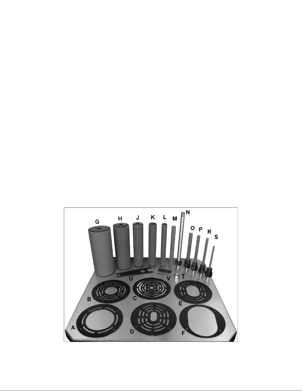
1 1/4” Spindle with sleeve – S
1 S pindle hex nut – T
1 Combination wrench (with magnet strip) – U
1 Hex wrench 3mm, and magnet strip – V
Note: All provided sanding sleeves are 100 grit.
Additional grits are available – see parts breakdown.
6.1 Shipping contents
Most of the below items can be found on or inside
sander cabinet. Some items are shipped in the small
box which accompanies the machine. One table
insert comes installed on the table.
Refer to Figure 1.
1 Spindle sander (not shown)
6 Table inserts:
for 4” rubber drum (at 90°) – A
for 2” rubber drum (at 90°) – B
for 3/8” spindle (at 90°) – C
for 1/4”-to-3/4” spindle (at tilt) – D
for 1”,1-1/2”,2” rubber drum (at tilt) – E
for 3” and 4” rubber drum (at tilt) – F
1 Rubber drum with sleeve 4” – G
1 Rubber drum with sleeve 3” – H
1 Rubber drum with sleeve 2” – J
1 Rubber drum with sleeve 1-1/2” – K
1 Rubber drum with sleeve 1” – L
1 3/4" sleeve – M
1 3/4" Spindle – N
1 5/8" Spindle with sleeve – O
1 1/2 ” Spindle with sleeve – P
1 3/8" Spindle with sleeve – R
6.2 Additional tools required
Ratchet wrench with socket set (or adjustable
wrench)
Cross-point (Phillips) screwdriver
Machinist square
Straight edge
6.3 Unpacking and cleanup
Inspect all contents from shipping carton, including
parts inside cabinet (accessed through the side
door). Report any damage or part shortages to your
distributor.
Exposed metal surfaces, such as table surface,
have been given a protective coating at the factory.
This coating should be removed with a soft cloth
moist e ned w it h sol ve nt, s uc h as m iner a l sp ir its. Do
not use solvents with low flash points, or allow
solvents near plastic or rubber parts. Do not use an
abrasive pad as it may scratch exposed surfaces.
Periodically apply a light coat of paste wax or other
protectant to the table top to prevent rusting.
Figure 1
7
Page 8
6.4 Removal from pallet
To remove sander from pallet:
1. Open cabinet door and remove accessories.
2. Use ratchet wrench with extended socket to
unscrew two bolts securing machine to pallet
(Figure 2).
3. Move sander off pallet, with help from an
assistant.
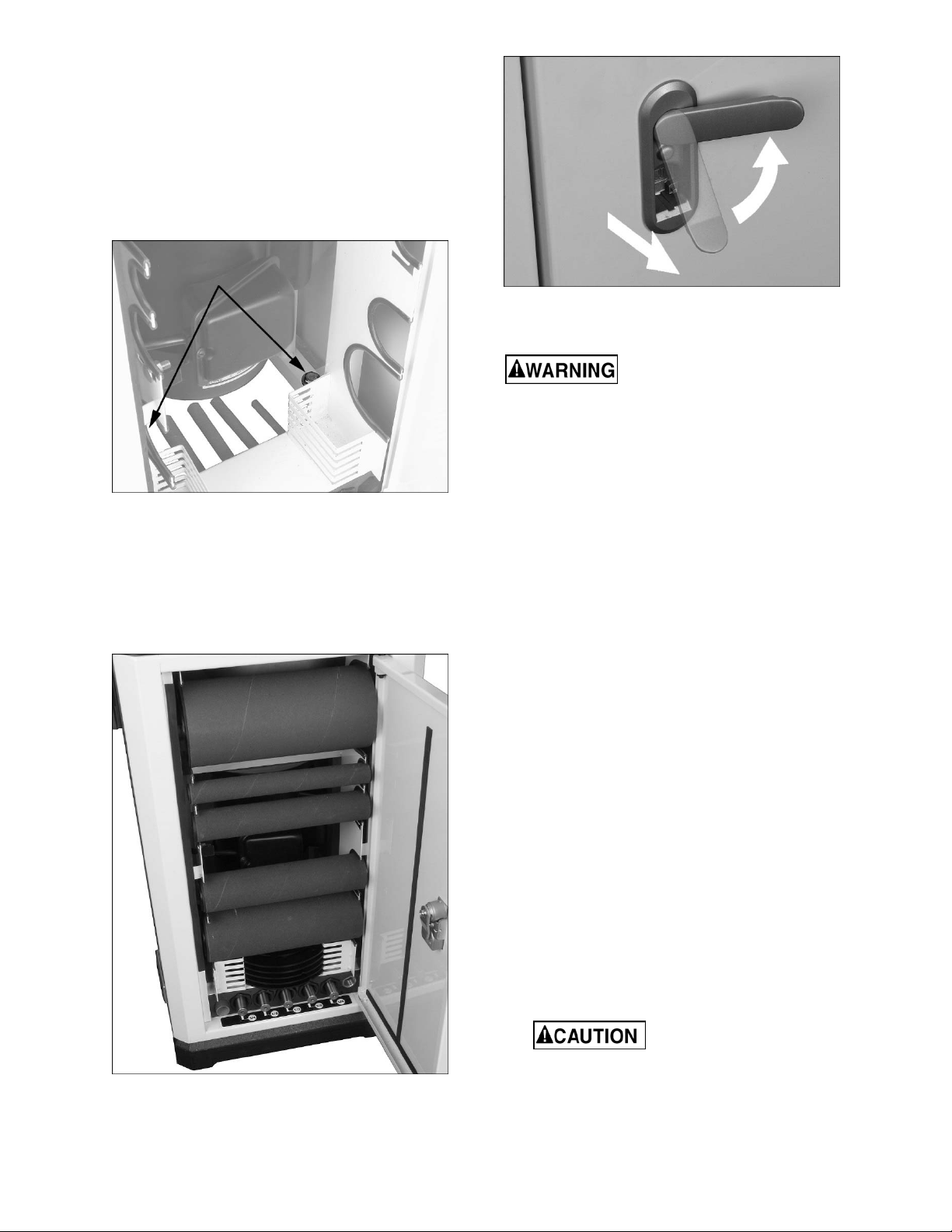
Figure 4: door latch
6.6 Installing/removing spindles
Disconnect sander from power
source when installing or removing sanding
assemblies. Failure to comply may cause
serious injury.
Open front shield (see sect. 8.1 Rubber Shields).
Figure 2: removal from pallet
6.5 Drum and spindle storage
Keep drums, spindles and table inserts protected by
storing them in cabinet (Figure 3). To open door, lift
bottom of latch and rotate counterclockwise 90
degrees (Figure 4). Reverse procedure to close
cabinet door.
Thoroughly clean tapered area (A, Figure 5) on all
spindle assemblies before installing. Also clean
mating shaft on sander.
Remove table insert if installe d.
Table may be tilted 15° backward to improve access
(see sect. 8.2.)
6.6.1 Small sleeve spindles
Refer to Figure 5.
1. Slide sanding sleeve (B) completely onto
spindle, ensuring that it slides into collar (C).
2. Tighten set screw on collar (C) w ith provided
3mm hex wrench. Do not overtight en.
3. P ull on sleeve to ensure it is secure.
4. Position spindle taper (A) into main shaft and
hold.
5. Rotate nut (D) clockwise by hand, as viewed
from above. Continue rotating nut until spindle
seats (stops turning with nut), then continue
rot a t ing n ut u nti l it is ha nd - tight.
6. Push in and hold spindle lock (E). Note: Rotate
spindle to ensure proper engagement.
7. Use provided combination wrench to tighten nut
further. Do not overtighten.
8. Release spindle lock. Make sure it retracts by
rotating spindle slightly.
Figure 3: cabinet storage
Make sure spindle lock has
fully disengaged before t urning on sander,
or damage to motor may result.
8
Page 9

Make sure spindle lock has
fully disengaged from spindle before
turning on sander, or damage to motor may
result.
To remove a spindle, reverse the above
procedure(s).
6.7 Installing table insert
Tools required:
cross-point screwdriver
straight edge
Failure to use proper table
insert with corresponding spindle/drum may
result in personal injury and/or damage to
workpiece.
Table inserts are round or oblong. Table 1 identifies
purpose of each.
Used with spindle
Insert
(diameter) Table angle
3” and 4”
drum
0 deg.
Figure 5: Spindle and drum mounting
6.6.2 Rubber drums
Refer to Figure 5.
1. Position spindle taper (A) into main shaft and
hold.
2. Rotate nut (D) clockwise by hand, as viewed
from above. Rotate nut until spindle seats
(stops turning with nut), then cont inue rotating
nut until it tightens.
3. Push and hold spindle lock (E). Note: Rotate
spindle to ensure proper engagement.
4. Use provided combination wrench to tighten nut
further. Do not overtighten.
5. Slide sanding sleeve completely onto drum until
its bottom edge is even with drum.
6. Slide drum/sleeve assembly down fully onto
spindle.
7. Push and hold spindle lock (E).
8. Install hex nut (F) onto spindle threads and
tighten clockwise (as viewed from above) with
provided combination wrench.
9. Pull on sleeve to ensure it is secure. If it slides,
tighten nut (F) a bit further. Do not overtighten.
10. Release spindle lock (E). Make sure it retracts
by rotating spindle slightly.
1/2, 5/8, 3/4,
1, 1-1/2, 2” drum
0 deg.
1/4” TO 3/8”
0 deg.
1/4, 3/8,1/2,5/8
and 3/4"
Up to
45 deg.
1, 1-1/2, 2”
drum
Up to
45 deg.
3” and 4”
drum
Up to
45 deg.
Table 1: Table insert identification
1. Position insert into table, so that notch is
captured by the pin (A , Figure 6).
2. Place straight edge over insert and table. If
gaps appear between straight edge a nd i nsert,
turn scr ew(s) to raise or lo wer inser t. Reposi tion
straight edge at right angle to check level in both
directions.
9
Page 10

Note: Leveling one insert is sufficient as all
inserts are same thickness.
Figure 6: mounting table insert
7.0 Electrical connections
The JOSS-S sander is rated at 115/230V power,
and is pre-wired for 115 volt. The sander comes with
a plug designed for use on a circuit with a grounded
outlet that looks like the one pictured in A, Figur e 8.
Before connect ing to power source, be sure switch
is in off position.
It is recommended that the JOSS-S sander be
connected to a dedicated 15 amp circuit with a 15
amp circuit breaker or time-delay fuse marked “D”.
Local codes take precede nce over r ecomm endations.
7.1 Grounding instructions
6.8 Wrench storage
The provided combination wrench has a magnetic
strip, and can be placed against any metal surface.
Expose the adhesive on the additional magnetic
strip and apply anywhere on the cabinet surface.
The hex key can be stored against it.
6.9 Dust collection
A sander produces a significant volume of wood
dust; the use of a dust collection system is strongly
recommended. It will help keep the shop clean, as
well as reduce potential healt h hazards caused by
inhalation of wood dust. The collector should h ave a
capacity sufficient for this size machine; minimum
300 CFM is recommended.
JET has a line of dust collection systems available;
see your dealer or visit our website listed on the
cover.
Connect the hose of your dust collection system to
the 4-inch dust port (Figure 7) at rear of sander.
Secure tightly with a hose clamp.
1. All Grounded, Cord-connected Tools:
In the event of a malfunction or breakdown,
grounding provides a path of least resistance for
electric current to reduce the risk of electric shock.
This tool is equipped with an electric cord having an
equipment-grounding conductor and a grounding
plug. The plug must be plugged into a matching
outlet that is properly installed and grounded in
accordance with all local codes and ordinances.
Do not modify the plug provided - if it will not fit the
outlet, have the proper outlet installed by a qualified
electrician.
Improper connection of the equipment-grounding
conductor can result in a risk of electric shock. The
cond uctor with insulation having an outer surf ace
that is green with or without yellow stripes is the
equipment-grounding conductor. If repair or
replacement of the electric cord or plug is
necessary, do not connect the equipment-grounding
conductor to a live terminal.
Check with a qualified
electrician or service personnel if the grounding
instructions are not completely understood, or if
in doubt as to whether the tool is properly
grounded. Failure to comply may cause serious
or fatal injury.
Use only 3-wire extension cords that have 3-prong
grounding plugs and 3-pole receptacles that accept
the tool's plug.
Figure 7
Repair or replace damaged or worn cord
immediately.
2. Grounded, cord-connected tools intended for use
on a supply circuit having a nominal rating less than
150 volts:
This tool is intended for use on a circuit that ha s a n
outlet that looks like the one illustrated in A, Figure
8. An adapter, shown in B and C, may be used to
connect this plug to a 2-pole receptacle as shown in
B if a properly grounded outlet is not available.
10
Page 11

The temporary adapter should be used only unt il a
properly grounded outlet can be installed by a
qualified electrician. This adapter is not permitted in
Canada. The green-colored rigid ear, lug, and the
like, extending from the adapter must be connected
to a permanent ground such as a properly grounded
outlet box.
Ampere
Rating
More
Than
Not
More
Than
00 06
06
10 12 16 16 14 12
12 16 14 12
10 18 16 14 12
Volts
120
240
AWG
18 16 16 14
Total length of
cord in f eet
25
50
100
50
100
200
Not
Recommended
150
300
Extension Cord Recommendations
Table 2
8.0 Adjustments
Figure 8
3. Grounded, cord-connected tools intended for use
on a supply circuit having a nominal rating between
150 - 250 volts, inclusive:
This tool is intended for use on a circuit that ha s a n
outlet that looks like the one illustrated in D, Figure
8. The tool has a grounding plug that looks like the
plug illustrated in D. Make sur e the tool is conn ected
to a n outlet having the sam e conf iguration a s the
plug. No adapter is available or should be used with
this tool. If the tool must be reconnected for use on
a different type of electric circuit, the reconnect ion
should be made by qualified service personnel; and
after reconnection, the tool should comply with all
local codes and ordinances.
7.2 Voltage conversion
To switch incoming power leads for 230 volt
operation, follow wiring diagram on ins ide cover of
motor junction box. A simi lar diagram is printed in
sect. 13. (In case of discrepancy, diagram on
machine takes precedence.)
The power cord plug must be replaced with a
UL/CSA listed plug rated for 230V.
Disconnect sander from power
source before making adjustments.
8.1 Rubber shields
Refer to Figures 9 and 10.
Front and rear rubber shields are co nnected at top
by hook-and-loop fasteners. Peel off top of shield to
access spindle area (Figure 9).
Figure 9: front shield
IMPORTANT: Before tilting table to maximum
degree forward, move top of shield from upper
position (A) to lower position (B).
7.3 Extension cords
The use of extension cords is discouraged; try to
position machines within reach of the receptacle. If
an extension cord is necessary, be sure to use one
heavy enough to carry the current your product will
draw. An undersized cord will ca use a drop in li ne
voltage resulting in loss of power and overheating.
Table 2 shows correct size to use depending on
cord length and nameplate ampere rating. If in
doubt, use the next heavier gauge. The smaller the
gauge number, the heavier the cord.
Figure 10: rear shield
11
Page 12

8.2 Table tilt for bevel sanding
Refer to Figures 11 and 12.
1. Loosen both knobs (A, Figure 11)
counterclockwise.
To tilt forward (45-degree maximum):
2. Move table by hand to desired angle shown on
scale (B). Scale is marked in 5-degree
increments.
3. Retighten knobs (A).
To tilt backward (15-degree maximum):
4. Pull out pin (C) and rotate it 90-degrees to keep
it disengaged.
5. Tilt table to desired position, and tighten knobs
(A).
5. If needed, loosen pointer (E) and align it wit h
zero degree mark.
6. Tilt tab le to 45-degrees and c heck accuracy of
45-degree stop screw (F). Adjust as needed.
Note: The above procedure is sufficient for most
wood sanding operations. If greater angle precision
is needed, remove insert and use a larger square
flush against a bare spindle and table surface to set
90-degree stop.
Figure 11: table tilt
Figure 12: table tilt
8.2.1 Setting 90- and 45-degree stops
Tools required:
machinist square
13mm wrench
Refer to Figures 11 through 13.
1. Make sure table insert has been leveled with
table (sect. 6.7).
2. Make sure pin (C) is re-engaged to contact stop
screw. Position table at zero (90-degrees)
against stop screw (D).
3. Place square on table and against front of drum
or spindle (Figure 13).
4. Rotate screw (D) until square sits flush against
table and spindle/drum.
Figure 13: setting tilt stop
9.0 Operations
9.1 Operating guidelines
1. Select spindle that is slightly smaller than curve
to be sanded.
2. Make sure spindle is properly secured on main
shaft.
3. Use table insert that has smallest opening
possible without contacting sanding sleeve.
4. Loosen both table handles and position table at
desired angle. Tighten both table handles
before operating.
5. Turn on sander and allow it to reach full speed
before starting work.
6. Hold workpiece firmly and against table at all
times.
7. For best results, keep workpiece moving
against spindle.
8. When table is at zero (90-degrees), workpiece
may approach sanding sleeve from any part of
table. When table is tilted, use tabl e area in front
of spindle.
12
Page 13

9. Sanding sleeve life may be prolonged by
reversing it on the spindle to make use of
opposite end.
Keep fingers clear of sanding
sleeve and table insert hole during operation.
9.2 Safety switch
Refer to Figure 14.
To start sander, push green button (A).
To stop sander, push red button (B).
Figure 14
10.2 Gearbox lubrication
Periodically check oil level at the sight glass (D,
Figure 15) – oil should be mid-level in the glass.
Use good quality SAE 90 gear oil.
Completely drain and refill after every 800 hours of
use. Oil capacity is 1.6 liters.
To drain and refill gearbox:
1. Remove accessories from inside cabinet to
access drain plug.
2. Remove drain plug (E, Figure 15) w ith 14mm
wrench. Dispose of used oil properly. Reinstall
drain plug.
3. Open rear shield, and clean area around oil
cap. Unscrew oil cap (F, Figure 16) by hand,
and remove spring.
4. Fi ll rese rvoir unti l oil level is at c enter of s ight
glass.
5. Reinstall spring and oil cap.
If power to the sander is
interrupted, the machine will restart immediately
once power is restored, unless the red stop
button has been pushed.
9.3 Safety key
The switch has a safety feature that prevents
unauthorized or accidental starting of the sander.
With sander turned off, slide safety key (C, Figure
14) upward and remove it f rom switch. Store in a
safe place. This piece must be re-inserted before
sander can operate.
10.0 Maintenance
Always disconnect power to
the machine before performing maintenance.
Failure to do this may result in serious personal
injury.
10.1 General maintenance
Clean the sander after each use. Vacuum any
residual dust inside the cabinet and around spindle
area.
Figure 15
Figure 16
Periodically apply a light coat of paste wax or other
protectant to the table surface to prevent rust.
All bearings are permanently lubricated and sealed;
no further lubrication required.
13
Page 14

11.0 Troubleshooting JOSS-S Spindle Sander
Symptom Possible Cause Correction
Sander will not start. Sander unplugged from wall or motor. Check all plug connections.
Fuse blown, or circuit breaker tripped
in service panel.
Cord damaged. Replace cord.
Starting capacitor bad. Replace starting capacitor.
Sanding drum does not
come up to speed.
Machine vibrates
excessively.
Sanded edge not
square.
Sanding mar ks on
wood.
Extension cord too light or too long. Replace with adequate size and length
Low current. Contact a qualified electrician.
Stand or base on uneven surface. Adjust stand or base so that it rests evenly
Bearings worn. Replace bearings.
Table not square to sanding drum. Use a square to adjust table to sanding
Wrong grit sanding sleeve. Use coarser grit for stock removal and fine
Feed pressure too great. Do not force workpiece against spindle or
12.0 Replacement Parts
Replace fuse, or reset circuit breaker.
cord.
on the floor.
drum.
grit for finish sanding.
drum.
Table 3
Replacement parts are listed on the following pages. To order parts or reach our service department, call 1-800274-6848 Monday through Friday, 8:00 a.m. to 5:00 p.m. CST. Having the Model Number and Serial Number of
your machine available when you call will allow us to serve you quickly and a ccurately.
14
Page 15

12.1.1 JOSS-S Table Assembly – Exploded View
15
Page 16

12.1.2 JOSS-S Table Assembly – Parts List
Index No P art No Description Size Qty
1 ................ SBR30M-62............... Spring Pin ................................................................ 5*20L............................. 1
2 ................ JOSS-S-102 .............. Table ........................................................................ ...................................... 1
3 ................ JOSS-S-103 .............. Phillips Flat Head Screw .......................................... M6*1.0P*15L ................. 4
4 ................ JOSS-S-104 .............. Hook-and-Loop Fastener (Male).............................. ...................................... 4
5 ................ JOSS-S-105 .............. Rubber Shield Holder .............................................. ...................................... 1
6 ................ TS-1550031 .............. Flat Washer ............................................................. 5.5*8*1T ...................... . 1
7 ................ JOSS-S-107 .............. Philli ps Round Head Screw ..................................... M 6 *1.0P*10L ................. 5
8 ................ JOSS-S-108 .............. Knob ........................................................................ ...................................... 1
9 ................ JOSS-S-109 .............. Stop Pin ................................................................... ...................................... 1
10 .............. JOSS-S-110 .............. Compression Spring ................................................ ...................................... 1
11 .............. JOSS-S-111 .............. Stop Pin Housing ..................................................... ...................................... 1
12 .............. 40345 ........................ Spring Pin ................................................................ 3*16L............................. 1
13 .............. JOSS-S-113 .............. Left Table Trunnion.................................................. ...................................... 1
14 .............. TS-2361101 .............. Lock Washer ............................................................ M10 ............................... 9
15 .............. TS-1491021 .............. Hex Cap Screw ........................................................ M10*1.5P*20L ............... 4
16 .............. TS-1512011 .............. Socket Head Flat Screw .......................................... M4*0.7P*10L ................. 2
17 .............. JOSS-S-117 .............. Guide Block ............................................................. ...................................... 2
18 .............. TS-1540061 .............. Hex Nut .................................................................... M8*1.25P ...................... 2
19 .............. TS-1490051 .............. Hex Cap Screw ........................................................ M8*1.25P*30L ............... 3
20 .............. JOSS-S-120 .............. Compression Spring ................................................ ...................................... 1
21 .............. OVS10-050 ............... Spring Pin ................................................................ 6*30L............................. 1
22 .............. JOSS-S-122 .............. Phillips Flat Head Screw .......................................... M5*0.8P*15L ................. 3
23 .............. JOSS-S-123 .............. Spindle Lock Seat .................................................... ...................................... 1
24 .............. JOSS-S-124 .............. Spindle Lock ........................................................... ...................................... 1
25 .............. JOSS-S-125 .............. Cap .......................................................................... ...................................... 1
26 .............. JOSS-S-126 .............. Hook-and-Loop Fastener (Female) ......................... ...................................... 2
27 .............. JOSS-S-127 .............. Phillips Round Head Screw ..................................... M6*1.0P*20L ................. 5
28 .............. JOSS-S-128 .............. Flat Washer ............................................................. 6.4*16*1.6T .................. 5
29 .............. TS-1540021 .............. Hex Nut .................................................................... M4*0.7P ........................ 3
30 .............. JOSS-S-130 .............. Rubber Shield Holder .............................................. ...................................... 1
31 .............. JOSS-S-131 .............. Phillips Round Head Screw ..................................... M5*0.8P*20L ................. 1
32 .............. JOSS-S-132 .............. Rubber Shield .......................................................... ...................................... 2
33 .............. JOSS-S-133 .............. Dust Chute Cover .................................................... ...................................... 1
34 .............. JOSS-S-134 .............. Phillips Round Head Screw ..................................... M4*0.7P*8L ................... 3
35 .............. JOSS-S-135 .............. Knob ........................................................................ ...................................... 2
36 .............. TS-1505061 .............. Socket Head Cap Screw.......................................... M10*1.5P*40L ............... 4
37 .............. TS-1540061 .............. Hex Nut .................................................................... M8*1.25P ...................... 6
38 .............. TS-1505021 .............. Socket Head Cap Screw.......................................... M10*1.5P*20L ............... 1
39 .............. JOSS-S-139 .............. Oil Filler Plug ........................................................... ...................................... 1
40 .............. TS-1490041 .............. Hex Cap Screw ........................................................ M8*1.25P*25L ............... 1
41 .............. JOSS-S-141 .............. Right Table Trunnion ............................................... ...................................... 1
42 .............. JOSS-S-142 .............. Pointer ..................................................................... ...................................... 1
43 .............. JOSS-S-131 .............. Phillips Round Head Screw ..................................... M5*0.8P*20L ................. 1
44 .............. JOSS-S-144 .............. Quill Housing ........................................................... ...................................... 1
45 .............. JOSS-S-145 .............. Knob Seat ................................................................ ...................................... 2
46 .............. JOSS-S-146 .............. Self Tapping Screw.................................................. 1/4"*1/2"L ...................... 4
47 .............. JOSS-S-147 .............. Collar ....................................................................... ...................................... 2
48 .............. TS-2361041 .............. Lock Washer ............................................................ M4 ................................. 2
49 .............. JOSS-S-149 .............. Phillips Round Head Screw ..................................... M4*0.7P*10L ................. 2
50 .............. JOSS-S-150 .............. Rubber Pad.............................................................. ...................................... 2
51 .............. TS-2311061 .............. Hex Nut .................................................................... M6*1.0P ........................ 5
52 .............. TS-2361081 .............. Lock Washer ............................................................ M8 ............................... 10
53 .............. TS-1504031 .............. Socket Head Cap Screw.......................................... M8*1.25P*16L ............... 6
54 .............. JOSS-S-154 .............. Retaining Ring ......................................................... ETW-5 ........................... 2
55 .............. JOSS-S-155 .............. Square Nut............................................................... M5*0.8P . ....................... 1
56 .............. TS-1541041 .............. Nylon Lock Hex Nut ................................................. M10*1.5P ...................... 3
57 .............. TS-1550071 .............. Flat Washer ............................................................. 10*20*2T ....................... 4
58 .............. JOSS-S-158 .............. Link .......................................................................... ...................................... 2
59 .............. JOSS-S-159 .............. Oilite Shaft Bushing ................................................ ...................................... 4
60 .............. JOSS-S-160 .............. Link Shaft ................................................................. ...................................... 1
16
Page 17

Index No P art No Description Size Qty
61 .............. JOSS-S-161 .............. Worm Gear Shaft ..................................................... ...................................... 1
62 .............. JOSS-S-162 .............. Guide Bar................................................................. ...................................... 1
63 .............. JOSS-S-163 .............. Retaining Ring ......................................................... STW-25 ......................... 1
64 .............. BB-6205VV ............... Ball Bearing ............................................................. 6205VV ......................... 2
65 .............. JOSS-S-165 .............. Quill.......................................................................... ...................................... 1
66 .............. JOSS-S-166 .............. Worm Gear .............................................................. ......... ............................. 1
67 .............. JOSS-S-167 .............. Worm Gear Fitting Bracket ...................................... ...................................... 1
68 .............. PM2800-039.............. Spring Pin ................................................................ 6*25L............................. 2
69 .............. JOSS-S-169 .............. Main Shaft................................................................ ...................................... 1
70 .............. JOSS-S-170 .............. Socket Head Cap Screw.......................................... M3*0.5P*14L ................. 2
71 .............. JOSS-S-171 .............. Key........................................................................... ...................................... 1
72 .............. JOSS-S-172 .............. Phillips Flat Head Screw .......................................... M5*0.8P*10L ................. 3
73 .............. JOSS-S-173 .............. Special Nut .............................................................. ...................................... 1
74 .............. JOSS-S-174 .............. Worm Shaft .............................................................. ...................................... 1
75 .............. OVS10-050 ............... Spring Pin ................................................................ 6*30L............................. 1
76 .............. JOSS-S-176 .............. Oil Seal .................................................................... 30*62*8T ....................... 1
77 .............. JOSS-S-177 .............. Retaining Ring ......................................................... RTW-62......................... 1
78 .............. JOSS-S-178 .............. Retaining Ring ......................................................... STW-30 ......................... 1
79 .............. BB-6206VV ............... Ball Bearing ............................................................ 6206VV ......................... 1
80 .............. JOSS-S-180 .............. Oil Tank ................................................................... ...................................... 1
81 .............. JOSS-S-181 .............. Oil Sight Glass ......................................................... ...................................... 1
82 .............. JOSS-S-182 .............. Oil Drain Plu g........................................................... PT-19, 1/4” .................... 1
83 .............. TS-1490031 .............. Hex Cap Screw ........................................................ M8*1.25P*20L ............... 4
84 .............. JOSS-S-184 .............. Shaft Coupling ......................................................... ...................................... 1
85 .............. JOSS-S-185 .............. Stop Bracket ............................................................ ...................................... 1
86 .............. JOSS-S-186 .............. Warning Label.......................................................... ...................................... 1
17
Page 18

12.2.1 JOSS-S Cabinet Assembly – Exploded View
2
4
1
4
4
3
4
4
5
4
7
4
7
0
6
0
5
0
0102030
7
2
33343536373
1
1
0
1
8
9
0
0
6
2
4
9
7
282
2
30313
1920212
2
2
3
0
4
8
242
9
9
8
3
3
4
0
5
9
4
6
4
5
2
8
161
1
7
1
020
5
1
4
1
3
1
2
1
18
Page 19

12.2.2 JOSS-S Cabinet Assembly – Parts List
Index No. Part No . Description Size Qty
1 ................ TS-2210451 .............. Hex Cap Screw ........................................................ M10*1.5P*45L ............... 8
2 ................ TS-2361101 .............. Lock Washer ............................................................ M10 ............................... 8
3 ................ 5051911 .................... Flat Washer ............................................................. 10*28*3T ....................... 4
4 ................ JOSS-S-204 .............. Cabinet .................................................................... ...................................... 1
5 ................ TS-1550021 .............. Flat Washer ............................................................. 4.3x10x1T ..................... 3
6 ................ JOSS-S-206 .............. Self Tapping Screw.................................................. M4*12L.......................... 3
7 ................ JOSS-S-207 .............. Philli ps Round Head Screw ..................................... M 5 *0.8P*12L ................. 2
8 ................ JOSS-S-208 .............. Star Washer ............................................................. M5 ................................. 4
9 ................ JOSS-S-209 .............. Door Catch............................................................... ...................................... 1
10 .............. TS-1550041 ............. Flat Washer ............................................................. 6.5*13*1T ...................... 1
11 .............. TS-2311061 .............. Hex Nut .................................................................... M6*1.0P ........................ 1
12 .............. JOSS-S-149 .............. Phillips Round Head Screw ..................................... M4*0.7P*10L ................. 1
13 .............. JOSS-S-213 .............. Switch ...................................................................... ...................................... 1
14 .............. JOSS-S-214 .............. Switch Box ............................................................... ...................................... 1
15 .............. TS-1540021 .............. Hex Nut .................................................................... M4*0.7P ........................ 1
16 .............. JOSS-S-216 .............. Strain Relief ............................................................. SB7R-3 ......................... 2
17 .............. JOSS-S-217 .............. Power Cord .............................................................. 3x16 AWG..................... 1
18 .............. JOSS-S-218 .............. Carriage Bolt ............................................................ M6*1.0P*12L ................. 1
19 .............. JOSS-S-219 .............. Coupling Cushion .................................................... ...................................... 1
20 .............. JOSS-S-220 .............. Key........................................................................... 5*5*25L ......................... 1
21 .............. TS-0270031 .............. Socket Set Screw .................................................... 5/16"-18UNC*3/8"L ....... 2
22 .............. JOSS-S-222 .............. Motor Coupling ........................................................ ...................................... 1
23 .............. JOSS-S-223 .............. Motor........................................................................ 1HP, 115/230V, 1Ph ..... 1
24 .............. JOSS-S-224 .............. Motor Cord ............................................................... ...................................... 1
25 .............. JOSS-S-225 .............. Base......................................................................... ...................................... 1
26 .............. JOSS-S-226 .............. Strain Relief ............................................................. PG 9 .............................. 1
27 .............. JOSS-S-227 .............. Sponge Strip ............................................................ 10*2*470mm ................. 2
28 .............. JOSS-S-228 .............. Edging Strip (for 4” Rubber Drum) ........................... ...................................... 2
29 .............. JOSS-S-229 .............. Edging Strip (for 1” Rubber Drum) ........................... ...................................... 2
30 .............. JOSS-S-230 .............. Edging Strip (for 1-1/2” Rubber Drum)..................... ...................................... 2
31 .............. JOSS-S-231 .............. Edging Strip (for 2” Rubber Drum) ........................... ...................................... 2
32 .............. JOSS-S-232 .............. Edging Strip (for 3” Rubber Drum) ........................... ...................................... 2
33 .............. JOSS-S-233 .............. Table Insert (for 1/4”~3/4” Spindle) .......................... ...................................... 1
34 .............. JOSS-S-234 .............. Table Insert (for 1”, 1-1/2”, 2” Rubber Drum) ........... ...................................... 1
35 .............. JOSS-S-235 .............. Table Insert (only for 3/8” spindle at 90 deg.) ......... ...................................... 1
36 .............. JOSS-S-236 .............. Table Insert (only for 2” Rubber Drum at 90 deg.) ... ...................................... 1
37 .............. JOSS-S-237 .............. Table Insert (only for 4” Rubber Drum at 90 deg.) ... ...................................... 1
38 .............. JOSS-S-238 .............. Table Insert for 3”, 4” Rubber Drum......................... ...................................... 1
39 .............. JOSS-S-239 .............. Spindle Seat ........................................................... ...................................... 1
40 .............. JOSS-S-240 .............. Sponge Strip ............................................................ 10*2*235mm ................. 1
41 .............. JOSS-S-241 .............. Cabinet Door............................................................ ...................................... 1
42 .............. JOSS-S-242 .............. Door Pivot ................................................................ ...................................... 1
43 .............. JOSS-S-243 .............. Compression Spring ................................................ ...................................... 1
44 .............. JOSS-S-244 .............. Retainer Ring ........................................................... ETW-5 ........................... 1
45 .............. JOSS-S-245 .............. Door Latch ............................................................... ...................................... 1
46 .............. JOSS-S-246 .............. Motor Label .............................................................. ...................................... 1
47 .............. JOSS-S-247 .............. ID Label ................................................................... ...................................... 1
48 .............. JOSS-S-248 .............. Shaft Size Indication Label ..................................... ...................................... 1
49 .............. JOSS-S-249 .............. Edging Strip (for 5/8”, 3/4” Shaft) ............................. ...................................... 1
50 .............. JOSS-S-250 .............. Edging Strip (for 1/4”, 3/8”, 1/2” Shaft)..................... ...................................... 1
.................. JET-92....................... JET Logo (not shown).............................................. 92x38mm ...................... 1
19
Page 20

12.3.1 JOSS-S Spindle and Drum Assembly– Exploded View
20
Page 21

12.3.2 JOSS-S Spindle and Drum Assembly– Parts List
Index No. Part No . Description Size Qty
1 ................ JOSS-S-301 ......... Combin ation Wrench .................................................... ...................................... 1
2 ................ JOSS-S-302 ......... Magnet (Large) ............................................................. ...................................... 1
3 ................ TS-152704 ........... Hex Wrench .................................................................. 3mm .............................. 1
4 ................ JOSS-S-304 ......... Magn et (Small) ............................................................. ...................................... 1
5 ................ TS-0571082 ......... Hex Nut ......................................................................... 3/4”-16UNF ................... 1
6 ................ JOSS-S-306 ......... Special Nut ................................................................... ...................................... 5
7 ................ JOSS-S-307 ......... Pin ................................................................................. 5*25............................... 5
8 ................ TS-2276081 ......... Socket Set Screw ......................................................... M6*1.0P*8L ................... 4
9 ................ JOSS-S-309 ......... Retainin g Ring .............................................................. STW-17 ......................... 4
10 .............. JOSS-S-310 ......... Spindle Assembly (incl. #6, 7, 8, 9, 11, 13 & 100G sleeve)….1/4” ...................... 1
11 .............. JOSS-S-311 ......... Spin dle .......................................................................... 1/4” ................................ 1
12 * ............ 575891 ................. Sanding Sleeve (60 Grit) – 4 pack ................................ 1/4” x 6” ...........................
.................. 575893 ................. Sanding Sleeve (100 Grit) – 4 pack .............................. 1/4” x 6” ...........................
.................. 575894 ................. Sanding Sleeve (150 Grit) – 4 pack .............................. 1/4” x 6” ...........................
13 .............. JOSS-S-313 ......... Collar (for 1/4” Spindle Assembly) ................................ ...................................... 1
14 .............. JOSS-S-314 ......... Spindle Assembly (incl. #6, 7, 8, 9, 15, 17 & 100G sleeve)….3/8” ...................... 1
15 .............. JOSS-S-315 ......... Spin dle .......................................................................... 3/8” ................................ 1
16 .............. 575896 ................. Sandin g Sleeve (60 Grit) – 4 pack ................................ 3/8” x 6” ...........................
.................. 575898 ................. Sanding Sleeve (100 Grit) – 4 pack .............................. 3/8” x 6” ...........................
.................. 575899 ................. Sanding Sleeve (150 Grit) – 4 pack .............................. 3/8” x 6” ...........................
17 .............. JOSS-S-317 ......... Collar (for 3/8” Spindle Assembly) ................................ ...................................... 1
18 .............. JOSS-S-318 ......... Spindle Assembly (incl. #6, 7, 8, 9, 19, 21 & 100G sleeve)…1/2” ....................... 1
19 .............. JOSS-S-319 ......... Spin dle .......................................................................... 1/2” ................................ 1
20 .............. 575901 ................. Sandin g Sleeve (60 Grit) – 4 pack ................................ 1/2” x 6” ...........................
.................. 575903 ................. Sanding Sleeve (100 Grit) – 4 pack .............................. 1/2” x 6” ...........................
21 .............. JOSS-S-321 ......... Collar (for 1/2” Spindle Assembly) ................................ ...................................... 1
22 .............. JOSS-S-322 ......... Spindle Assembly (incl. #6, 7, 8, 9, 23, 25 & 100G sleeve)….5/8” ...................... 1
23 .............. JOSS-S-323 ......... Spin dle .......................................................................... 5/8” ................................ 1
24 .............. 575906 ................. Sandin g Sleeve (60 Grit) – 4 pack ................................ 5/8” x 6” ...........................
.................. 575908 ................. Sanding Sleeve (100 Grit) – 4 pack .............................. 5/8” x 6” ...........................
.................. 575909 ................. Sanding Sleeve (150 Grit) – 4 pack .............................. 5/8” x 6” ...........................
25 .............. JOSS-S-325 ......... Collar (for 5/8” Spindle Assembly) ................................ ...................................... 1
26 .............. JOSS-S-326 ......... Spindle Assembly (incl. #6, 7, 27 & 100G sleeve) ........ 3/4” ................................ 1
27 .............. JOSS-S-327 ......... Spin dle .......................................................................... 3/4” ................................ 1
28 .............. 575911 ................. Sandin g Sleeve (60 Grit) – 4 pack ................................ 3/4” x 9” ...........................
.................. 575913 ................. Sanding Sleeve (100 Grit) – 4 pack .............................. 3/4” x 9” ...........................
.................. 575914 ................. Sanding Sleeve (150 Grit) – 4 pack .............................. 3/4” x 9” ...........................
29 .............. JOSS-S-329 ......... Self Tapping Screw ....................................................... M 3*12L........................ 12
30 .............. JOSS-S-330 ......... Drum Ass e mbl y (incl. #31 & 100G sleeve) ................... 1” ................................... 1
31 .............. JOSS-S-331 ......... Rubber Drum ................................................................ 1” ................................... 1
32 .............. 575916 ................. Sandin g Sleeve (60 Grit) – 4 pack ................................ 1” x 9” ..............................
.................. 575918 ................. Sandin g Sleeve (100 Grit) – 4 pack .............................. 1” x 9” ..............................
.................. 575919 ................. Sandin g Sleeve (150 Grit) – 4 pack .............................. 1” x 9” ..............................
33 .............. JOSS-S-333 ......... Drum Ass e mbly (incl. #34 & 100G sleeve) ................... 1-1/2”............................. 1
34 .............. JOSS-S-334 ......... Rubber Drum ................................................................ 1-1/2”............................. 1
35 .............. 575926 ................. Sandin g Sleeve (60 Grit) – 4 pack ................................ 1-1/2” x 9”........................
.................. 575928 ................. Sanding Sleeve (100 Grit) – 4 pack .............................. 1-1/2” x 9”........................
.................. 575929 ................. Sanding Sleeve (150 Grit) – 4 pack .............................. 1-1/2” x 9”........................
36 .............. JOSS-S-336 ......... Drum Assembly (incl.#29, 37, 39, & 100G sleeve) ....... 2” ................................... 1
37 .............. JOSS-S-337 ......... Rubber Drum ................................................................ 2” ................................... 1
38 .............. 575936 ................. Sandin g Sleeve (60 Grit) – 4 pack ................................ 2” x 9” ..............................
.................. 575938 ................. Sandin g Sleeve (100 Grit) – 4 pack .............................. 2” x 9’ ..............................
.................. 575939 ................. Sandin g Sleeve (150 Grit) – 4 pack .............................. 2” x 9” ..............................
39 .............. JOSS-S-339 ......... Washer ......................................................................... 2” ................................... 2
40 .............. JOSS-S-340 ......... Drum Assembly (incl.#29, 41, 43 & 100G sleeve) ........ 3” ................................... 1
41 .............. JOSS-S-341 ......... Rubber Drum ................................................................ 3” ................................... 1
* NOTE: 1/4 x 6-inch sleeves must be cut by customer to 5” length to fit spindle on JOSS-S.
21
Page 22

Index No. Part No . Description Size Qty
42 .............. 575946 ................. Sandin g Sleeve (60 Grit) – 4 pack ................................ 3” x 9” ..............................
.................. 575948 ................. Sandin g Sleeve (100 Grit) – 4 pack .............................. 3” x 9” ..............................
.................. 575949 ................. Sandin g Sleeve (150 Grit) – 4 pack .............................. 3” x 9” ..............................
43 .............. JOSS-S-343 ......... Washer ......................................................................... 3” ................................... 2
44 .............. JOSS-S-344 ......... Drum Assembly (incl.#29, 45, 47 & 100G sleeve) ........ 4” ................................... 1
45 .............. JOSS-S-345 ......... Rubber Drum ................................................................ 4” ................................... 1
46 .............. 575951 ................. Sandin g Sleeve (60 Grit) – 4 pack ................................ 4” x 9” ..............................
.................. 575953 ................. Sandin g Sleeve (100 Grit) – 4 pack .............................. 4” x 9” ..............................
.................. 575954 ................. Sandin g Sleeve (150 Grit) – 4 pack .............................. 4” x 9” ..............................
47 .............. JOSS-S-347 ......... Washer ......................................................................... 4” ................................... 2
22
Page 23

13.0 Electrical Connections – JOSS-S Spindle Sander
23
Page 24

427 New Sanford Road
LaVergne, Tennessee 37086
Phone: 800-274-6848
www.jettools.com
24
 Loading...