

Page 1

Assembly and Parts List
Folding Infeed/Outfeed Tables
for JWDS-2244, JWDS-2244OSC, and JWDS-2550 Drum Sanders
IMPORTANT SAFETY INSTRUCTIONS
• Read and understand entire owner's manual for your Drum Sander before attempting assembly or operation.
• Read and understand the warnings posted on the machi ne and in the manual. Failure to comply with all of
these warnings may cause serious injury.
• Replace warning labels if they become obscured or removed.
• WARNING: This product can expose you to chemicals including lead which is known to the State of
California to cause cancer and birth defects or other reproductive harm. For more information go to
http://www.p65warnings.ca.gov.
Open shipping carton and compare contents with
the following parts list to make sure all parts are
intact. Report any missing parts to your distributor.
Contents:
2 Infeed/Outfeed Tables – D
1 Rear (short) Fixed Bracket – E
1 Front (long) Fixed Bracket – F
2 Left Folding Table Brackets – G
2 Right Folding Table Brackets – H
1 Assembly and Parts List
1 Hardware Package, includes:
4 Locking handles – HP1
4 Disc washers – HP2
4 Oilite washers – HP3
16 Socket hd cap screws M8x16 – HP4
16 Flat washers M8 – HP5
4 Socket hd cap screws M6x20 – HP6
4 Flat washers M6 – HP7
4 Eccentric cams – HP8
Tools required for assembly
5mm, 6mm hex (Allen) wrenches
Straight edge (such as straight steel bar or carefully
jointed board)
JET
427 New Sanford Road
LaVergne, Tennessee 37086 Part No. M-723541
Ph.: 800-274-6848 Edition 2 10/2018
www.jettools.com Copyright © 2018 JET, a division of JPW Industries, Inc
Figure 1: Contents
Page 2

Figure 2: Assembly of Infeed/Outfeed Tables to Drum Sander
Assembly
The sander must be bolted to the stand or a work
table when using these table extensions. Maximum
working load of each table is 35 pounds. Fasteners
are provided with the extension tables.
NOTE: If using the folding feature of the
infeed/outfeed tables, make sure your table or
bench allows for such vertical drop at front and back.
To install infeed table:
1. Install front (F) fixed bracket to threaded holes
in sander base with screws and washers
(HP4/5). Make sure bracket is oriented as
shown. Bracket must be flush against base.
NOTE: Long bracket mounts to front
(infeed); short bracket to rear (outfeed).
2. Tighten screws (HP4).
3. Install eccentric cam (HP8) with screw and
washer (HP6/7). Finger tighten only at this time.
4. Install left (G) and right (H) table brackets, using
handles and washers (HP1/2/3).
Note: Handle (HP1) is adjustable – pull up and
rotate on pin to more convenient position, then
release allowing it to settle back onto pin.
5. Place infeed table (D) onto table brackets and
secure with screws and washers (HP4/5).
Finger tighten only.
Align infeed table with sander’s conveyor table as
follows. See Figures 3 and 4.
6. Place a straight-edge at one side of conveyor
table under drum and extending out over infeed
table. See Figure 3. You may wish to lower
drum until it contacts the straight edge to hold it
in place.
7. Raise infeed table until it evenly contacts
straight edge. If needed, loosen four screws
(HP4) beneath table and adjust table to level.
Tighten screws.
8. Loosen screw (HP6) and rotate eccentric cam
(HP8) until it contacts lip of table bracket. Do
this on both sides of infeed table. This ensures
infeed table will remain level with conveyor
table each time it is returned to operating
position. Tighten screws (HP6).
9. Install outfeed table using identical procedure
as above.
Figure 3: infeed table alignment
2
Page 3

TIP: It is often preferable to position infeed/ outfeed
tables slightly below conveyor table surface,
particularly if stock being sanded is bowed, warped
or otherwise inconsistent. Also, if stock slips on
conveyor, the tables may be positioned too high.
Adjustment
The tables can be swung down to allow easier
access for abrasive wrapping or other adjustments.
Loosen handles on each side, slide table away from
machine and then down. See Figure 4.
Specifications
Figure 4
Stock no.
Fits model JWDS-2244 JWDS-2550 / JWDS-2244OSC
Table size 22 x 10-1/4 in. (559 x 260mm) 26 x 10-1/4 in. (660 x 260mm)
Net weight (approx.) 23 lbs. (11 kg) 26 lbs. (12 kg)
Shipping weight (approx.) 28 lbs. (13 kg) 31 lbs. (14 kg)
723541 723551
Replacement Parts
Replacement parts are listed on the following page. To order parts or reach our s ervice depart ment, call 1-800274-6848 Monday through Friday, 8:00 a.m. to 5:00 p.m. CST. Having the Model Number and Serial Number of
your machine available when you call will allow us to serve you quickly and accurately.
Non-proprietary parts, such as fasteners, can be found at local hardware stores, or may be ordered from JET.
Some parts are shown for reference only, and may not be available individually.
3
Page 4
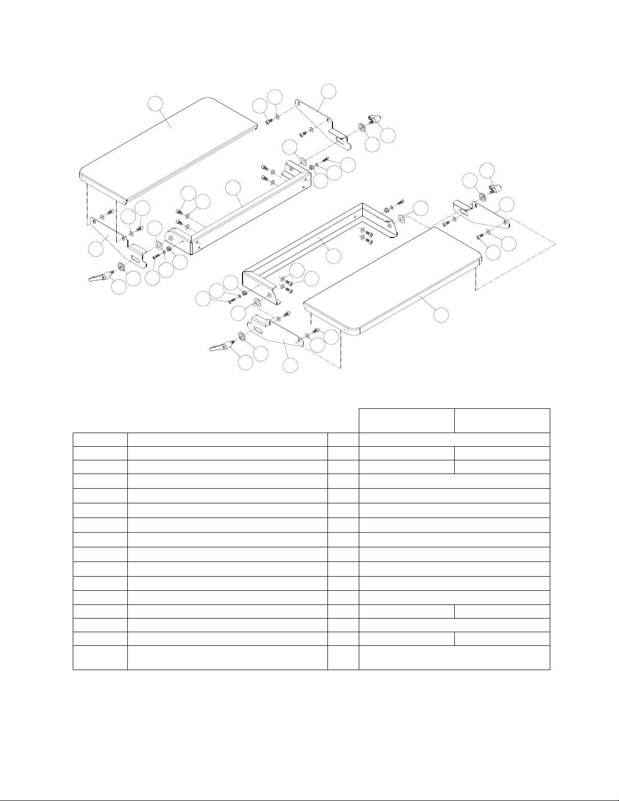
Folding Infeed/Outfeed Tables for JWDS-2244/-2244OSC/-2550
1
3
2
4
5
7
9
2
2
11
3
10
6
8
5
6
7
12
3
7
12
10
6
5
10
9
8
9
8
3
7
13
2
1
2
3
3
2
6
5
4
JWDS-2244 JWDS-2550
JWDS-2244OSC
Index No. Description Qty. Part No.
Folding Infeed/Outfeed Tables (#1-13) 723541 723551
1 Extension Table 2 JWDS2244-401 JWDS2550-401
2 Socket Head Cap Screw M8-1.25P x 16L 16 TS-1504031
3 Flat Washer 8.3 x 20 x 1.5T mm 16 TS-1550061
4 Left Folding Table Bracket 2 JWDS2244-404
5 Handle 4 JWDS2244-405
6 Disc Washer 4 JWDS2244-406
7 Oilite Washer 4 JWDS2244-407
8 Socket Head Cap Screw M6-1.0P x 20L 4 TS-1503051
9 Flat Washer 6.3 x 13 x 2T mm 4 TS-1550041
10 Eccentric Cam 4 JWDS2244-410
11 Rear Fixed Bracket 1 JWDS2244-411 JWDS2550-411
12 Right Folding Table Bracket 2 JWDS2244-412
13 Front Fixed Bracket 1 JWDS2244-413 JWDS2550-413
Hardware Package, Infeed-Outfeed Tables
(includes #2,3,5,6,7-10)
JWDS2244-420
4
 Loading...