

Page 1
This .pdf document is bookmarked
Operating Instructions and Parts Manual
8-inch Woodworking Jointer
Models JJ- 8C S an d JJ- 8 HH
Model JJ-8CS Model JJ-8HH
JET
427 New Sanford Road
LaVergne, Tennessee 37086 Part No. M-708458
Ph.: 800-274-6848 Revision H2 02/2014
www.jettools.com Copyright © 2014 JET
Page 2

Warranty and Service
JET warrants every product it sells against manufacturers’ defects. If one of our tools needs service or repair, please
contact Technical Service by calling 1-800-274-6846, 8AM to 5PM CST, Monday through Friday.
Warranty Period
The general warranty lasts for the time period specified in the literature included with your product or on the official
JET branded website.
• JET products carry a limited warranty which varies in duration based upon the product. (See chart below)
• Accessories carry a limited warranty of one year from the date of receipt.
• Consumable items are defined as expendable parts or accessories expected to become inoperable within a
reasonable amount of use and are covered by a 90 day limited warranty against manufacturer’s defects.
Who is Covered
This warranty covers only the initial purchaser of the product from the date of delivery.
What is Co vered
This warranty covers any defects in workmanship or materials subject to the limitations stated below. This warranty
does not cover failures due directly or indirectly to misuse, abuse, negligence or accidents, normal wear-and-tear,
improper repair, alterations or lack of maintenance.
Warranty Limitations
Woodworking products with a Five Year Warranty that are used for commercial or industrial purposes default to a
Two Year Warranty. Please contact Technical Service at 1-800-274-6846 for further clarification.
How to Get Technical Support
Please contact Technical Service by calling 1-800-274-6846. Please note that you will be asked to provide proof
of initia l p u rch a s e whe n calling. If a product requires further inspection, the Technical Service representative will
explain and assist with any additional action needed. JET has Authorized Service Centers located throughout the
United States. For the name of an Authorized Service Center in your area call 1-800-274-6846 or use the Service
Center Locator on the JET website.
More Informa tion
JET is constantly adding new products. For complete, up-to-date product information, check with your local distributor
or visit the JET website.
How S tate Law Applies
This warranty gives you specific legal rights, subject to applicable state law.
Limitations on This Warranty
JET LIMITS ALL IMPLIED WARRANTIES TO THE PERIOD OF THE LIMITED WARRANTY FOR EACH PRODUCT.
EXCEPT AS STATED HEREIN, ANY IMPLIED WARRANTIES OF MERCHANTABILITY AND FITNESS FOR A
PARTICULAR PURPOSE ARE EXCLUDED. SOME STATES DO NOT ALLOW LIMITATIONS ON HOW LONG AN
IMPLIED WARRANTY LASTS, SO THE ABOVE LIMITATION MAY NOT APPLY TO YOU.
JET SHALL IN NO EVENT BE LIABLE FOR DEATH, INJURIES TO PERSONS OR PROPERTY, OR FOR
INCIDENTAL, CONTINGENT, SPECIAL, OR CONSEQUENTIAL DAMAGES ARISING FROM THE USE OF OUR
PRODUCTS. SOME STATES DO NOT ALLOW THE EXCLUSION OR LIMITATION OF INCIDENTAL OR
CONSEQUENTIAL DAMAGES, SO THE ABOVE LIMITATION OR EXCLUSION MAY NOT APPLY TO YOU.
JET sells through distributors only. The specifications listed in JET printed materials and on official JET website are
given as general information and are not binding. JET reserves the right to effect at any time, without prior notice,
those alterations to parts, fittings, and accessory equipment which they may deem necessary for any reason
whatsoever. JET
Product Listing with Warranty Period
90 Days – Parts; Consumable items; Light-Duty Air Tools
1 Year – Motors; Machine Accessories; Heavy-Duty Air Tools; Pro-Duty Air Tools
2 Year – Metalworking Machinery; Electric Hoists, Electric Hoist Accessories; Woodworking Machinery used
for industrial or commercial purposes
5 Year – Woodworking Machinery
Limited Lifetime – JET Parallel clamps; VOLT Series Electric Hoists; Manual Hoists; Manual Hoist
Accessories; Shop Tools; Warehouse & Dock products; Hand Tools
NOTE: JET is a division of JPW Industries, Inc. References in this document to JET also apply to JPW Industries,
Inc., or any of its successors in interest to the JET brand.
®
branded products are not sold in Canada by JPW Industries, Inc.
2
Page 3

Table of Contents
Warranty and Servic e .............................................................................................................................. 2
Table of Contents .................................................................................................................................... 3
Warning ................................................................................................................................................... 4
Introduction ............................................................................................................................................. 5
Levers and Controls ................................................................................................................................ 6
Specifica tions ................................................................................................................ .......................... 6
Unpacking and Cleanup .......................................................................................................................... 7
Unpacking and Cleanup ....................................................................................................................... 7
Installing B ed to Stand ......................................................................................................................... 8
Installing P edest al Switch (JJ-8HH only) .............................................................................................. 8
Installing Handwheel s .......................................................................................................................... 9
Assembling Knife-Setting Gauge (JJ-8CS only) .................................................................................... 9
Installing V-Belts .................................................................................................................................. 9
Installing Cutterhead Guard ................................................................................................................ 10
Installing Access Door ........................................................................................................................ 10
Installing Dust Chute .......................................................................................................................... 10
Electri c al Connec tions ........................................................................................................................ 10
Extension Cords................................................................................................................................. 11
Adjustments .......................................................................................................................................... 11
90° Fence Adjustment ........................................................................................................................ 11
45° Fence Adjustment ........................................................................................................................ 12
Leveling Outfeed Table to Cutterhead Knives .................................................................................... 12
Removing and Replacing Knives (JJ-8CS only) .................................................................................. 14
Replacing or Rotating Knife Inserts (JJ-8HH only) .............................................................................. 14
Gib Adjustment .................................................................................................................................. 15
Operation .............................................................................................................................................. 1 5
Jointing Warped Material .................................................................................................................... 16
Direction of Grai n ............................................................................................................................... 16
Bevel Cut ........................................................................................................................................... 16
Taper Cut ........................................................................................................................................... 17
Rabbet Cut ........................................................................................................................................ 17
Maintenance .......................................................................................................................................... 18
Lubrication ......................................................................................................................................... 18
Blade Care ......................................................................................................................................... 18
Sharpening the Kniv es (J J - 8CS only ) ................................................................................................. 18
Cutterhead Rem ov al .......................................................................................................................... 1 8
Replacement Parts ................................................................................................................................ 20
Fence As sembly (al l mod els) ................................................................................................... .......... 21
Parts List – Fence Assembly (all models) ........................................................................................... 21
Bed Assembly (all models) ................................................................................................................. 22
Parts List – Bed Assembly ( all m odels) ............................................................................................... 23
Stand and Motor Assembl y (JJ- 8CS only) .......................................................................................... 24
Parts List – Stand and Mot or Assembl y (JJ - 8CS only ) ........................................................................ 25
Stand and Motor Assembl y (JJ- 8HH only ) .......................................................................................... 26
Parts List – Stand and Mot or Assembl y (JJ-8HH only) ........................................................................ 27
Parts List – Cutterhead A ssembly (JJ-8CS only)................................................................................. 28
Parts List – Cutterhead A ssembly (JJ-8HH only) ................................................................................ 29
Electri c al Connec tions (JJ-8CS only) .................................................................................................. 30
Electric al Connec tions (JJ-8HH only).................................................................................................. 31
3
Page 4

Warning
1. Read and understand t he entire owners manual bef or e attempti ng assem bly or operation.
2. Read and understand the warning s posted on t he m achine and i n this manual. Failure t o comply wit h
all of these warnings m ay cause seriou s i njury.
3. Replace t he warning labels if they become obscured or removed.
4. This jointer is designed and i ntended for use by prope rly trai ned and experienced personnel only. If
you are not familiar with the proper and safe operation of a jointer, do not use until proper training and
knowledge have been obtained.
5. Do not use this j ointer for ot her than i ts intended u se. If used for ot her purpos es, JET di sclaim s any
real or implied warranty and holds itself harmless from any injury that m ay result from that use.
6. Always wear approved safet y glasses/face shi elds while using thi s jointer. Ev eryday eyeglasses only
have impact resistant lenses; they are not safety glasses.
7. Before operati ng this jointer, remove tie, rings, watches an d other jewelry, and roll sleeves up past
the elbows. Remove all loose clothing and confine long hair. Non- sl ip footwear or anti-skid floor st r ips
are recommended. Do not wear gloves.
8. Wear ear protectors (plugs or muffs) during ex tended periods of operation.
9. Some dust created by power sanding, sawing, grinding, drilling and other construction activities
contains chemicals known to cause c anc er , birth defects or other reproductive harm. Some examples
of these chemic als are:
• Lead from lead based paint.
• Crystalli ne sil ic a from bricks, cement and other masonry produc ts.
• Arsenic and chromium from chemically treated lumber.
Your risk of exposure varies, depending on how often you do this type of work. To reduce your
exposure to these chemicals, work in a well-ventilated area and work with approved safety
equipment, such as face or dust masks that are specifically designed to filter out microscopic
particles.
10. Do not oper ate this machine while tired or under t he influence of drugs, alcohol or any medic ation.
11. Make c er tain the switch is in the OFF position before connecting the machine to the power supply.
12. Make c er tain the machine is properly grounded.
13. Make all machine adjustments or mai ntenance with the machine unplugged from the power source.
14. Remove adjusting keys and wrenches. Form a habit of checking to see that keys and adjusting
wrenches are removed from the machine before turning i t on.
15. Keep safety guards in place at all times when the machine is in use. If removed for maintenance
purposes, use extreme caution and replace the guards immediately.
16. Make sure t he jointer is firmly secured to the stand or a bench before use.
17. Check damaged parts. Before further use of the machine, a guard or other part that is damaged
should be carefully checked to determine that it will operate properly and perform its intended
function. Chec k for alignment of moving par ts, binding of moving parts, breakage of parts, mounting
and any other condi ti ons that m ay affect its operati on. A guard or ot her part that i s damaged should
be properly repaired or replaced.
18. Prov ide for adequate space surrounding work area and non-glare, over head lighting.
19. Keep t he floor around the machine clean and free of scrap mater ial, oil and grease.
20. Keep visitors a safe distance from the work area. Keep children away.
4
Page 5

21. Make y our workshop child proof with padlock s, m aster switches or by removing starter k ey s.
22. Giv e your work undivi ded attention. Looki ng around, carryi ng on a conversati on and “horse-play” ar e
careless acts that can r esul t in serious injury.
23. Maintai n a balanced stance at all times so that you do not fall or lean against t he knives or other
moving part s. Do not over r eac h or use excessive force to perform any machine oper ation.
24. Use the right tool at the correc t speed and f eed rat e. Do not force a t ool or attac hment to do a j ob for
which it was not designed. T he ri ght tool will do the job better and saf er.
25. Use recommended accessories; improper accessories may be hazardous.
26. Mai ntain tools with care. K eep knives sharp and clea n for the best and saf est performance. Foll ow
instructions for lubricating and changi ng ac c essori es.
27. Turn of f the m achine and discon nect f rom power bef ore cleani ng. Use a bru sh or com pressed air to
remove chips or debris — do not use your hands.
28. Do not stand on the machine. Serious injury c ould oc c ur if the mac hi ne tips over.
29. Never leave the machine runni ng unattended. Turn the power off and do not leave the machine until it
comes to a complete stop.
30. Remove loose items and unnecessary work pieces from the area before starti ng the mac hine.
Familiariz e you rself with the following safety notices u sed in this manual:
This means that if precautions are not heeded, it may result in mi nor i njur y and/or
possible machine damage.
This means that if precautions are not heeded, it may result in serious injury or possibly
even death.
Introduction
This manual is provi ded by JET covering the saf e operation and mai ntenance procedures for the JET
Model JJ-8CS and JJ-8HH Woodworking Jointers. This manual contains instructions on installation,
safety prec autions, general operating pr ocedures, maintenance i nstructi ons and parts breakdo wn. This
machine has been designed and constructed to provide years of trouble free operation if used in
accordance with instructions set forth in this manual. If there are any questions or comments, please
contact eit her y our l oc al suppli er or JET. JET can also be reached at our web site: www.jettools.c om .
5
Page 6
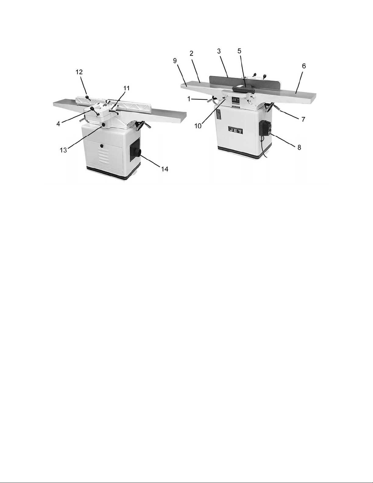
Levers and Controls
1. Handwheel for Outf eed Table 8. On/Off Switch (Pedestal style on JJ-8HH)
2. Outfeed Table 9. Rabbeting Ledge
3. Fence 10. Table Lock Knob
4. Fence Adjustment Handle 11. Fence Tilt Lock Handle
5. Cutter Guard 12. Fence Contr ol Handle
6. Infeed Table 13. Belt Guard
7. Handwheel for Infeed Table 14. Dust Chute
Specifications
Model JJ-8CS JJ-8HH
Stock Number – Bed and Stand Kit ................................ 708458K................................................ 708468K
Stock Number – Bed Assembly ..................................... 708458J................................................. 708468J
Stock Number Stand...................................................... 708458S................................................ 708460S
Cutting Capacity ....................................................... 8"W x 1/2"D ........................................... 8"W x 1/2"D
Cutterhead Speed ...................................................... 5500 RPM.............................................. 5500 RPM
Number of Knives ...................................................................... 3....................................... 36 knife inserts
Rabbeting Capaci ty .............................................................. 1/2"......................................... not applicable
Rabbet Ledge ........................................................ 3-1/8" x 8-3/4 "........................................ 3-1/8" x 8-3/4"
Table Surface .......................................................9”W x 66-1/2”L....................................... 9”W x 66-1/2”L
Fence ...................................................................4”W x 38-1/2”L....................................... 4”W x 38-1/2”L
Knife Size .................................................. 8”L x 11/16”W x 1/8”T......................... 0.59”L x 0.59”W x 0.10T
Fence Tilt ................................................................... 45ºL, 45ºR ............................................ 45ºL , 45ºR
Positive Stops...................................................... 45ºL, 90º, 45ºR...................................... 45ºL, 90º, 45ºR
Motor ................................................ 2HP, 1Ph, 60Hz, 230V only.................... 2HP, 1Ph, 60Hz, 230V only
Net Weight, Joint er and Stand ( appr ox .) ......................... 400 lbs.................................................... 411 lbs
Shipping Weight , Jointer and Stand ................................ 495 lbs.................................................... 505 lbs
The above specifications were current at the time this manual was published, but because of our policy of
continuous impr ovement, JET reserves the ri ght to change specific ations at any time and without prior
notice, without incurring obligations.
6
Page 7

Unpacking and Cleanup
Cont en ts of Shipping Carton s
Note: Unit shipped in two cartons.
Stand Carton
1 Stand with Mot or
1 Stand Door
1 Dust Chute with Mounting Hardware
1 Pedestal Switc h with Mounting Hardware
(JJ-8HH only)
Main Unit Carton
1 Bed Assembly
1 Fence Assembly
1 Cutterhead Guard
1 Belt Guard
2 V-Belts
2 Handwheels with handle
1 Fence Handle
3 Mounting Bolts
3 3/8" Lock Washers
1 Operating Instr uc tions and Parts Manual
1 Warranty Card
Tools Included with JJ-8CS
1 12/14mm Open End Wr enc h
1 8/10mm Open End Wrench
3 Hex Wrenches (3, 4 and 5 mm)
1 Knife Gauge Assembly
Tools included with JJ-8HH:
1 12/14mm Open End Wr enc h
1 8/10mm Open End Wrench
4 Hex Wrenches (3, 4, 5, 6 mm)
2 Star Point Screwdrivers
5 Knife Inserts
10 Knife Insert Screws
Tools Required for Assembl y:
#1 Cross Point Screwdriver
6-8” Adjustable Wrench or 17 & 19mm Wrench
Unpacking and Cleanup
1. Carefully finish removing all contents from
both shipping car tons. Compare cont ents of
the shipping car tons with the l ist of content s
above. Place part s on a prot ec ted surface.
2. Set packing material and shippi ng c ar tons to
the side. Do not discard until machine has
been set up and is running properly.
3. Clean all rust protected surfaces (bed,
fence, etc.) with kerosene or diesel oil. Do
not use gasoline, paint thinner, mineral
spirits, etc. These may damage painted
surfaces.
7
Page 8
Cutterhead knives are
dangerously sharp! Use
extreme cautio n when cl eani ng.
4. Appl y a thi n layer of paste wax t o the bright
surfaces of the fence and t ables to prevent
rust.
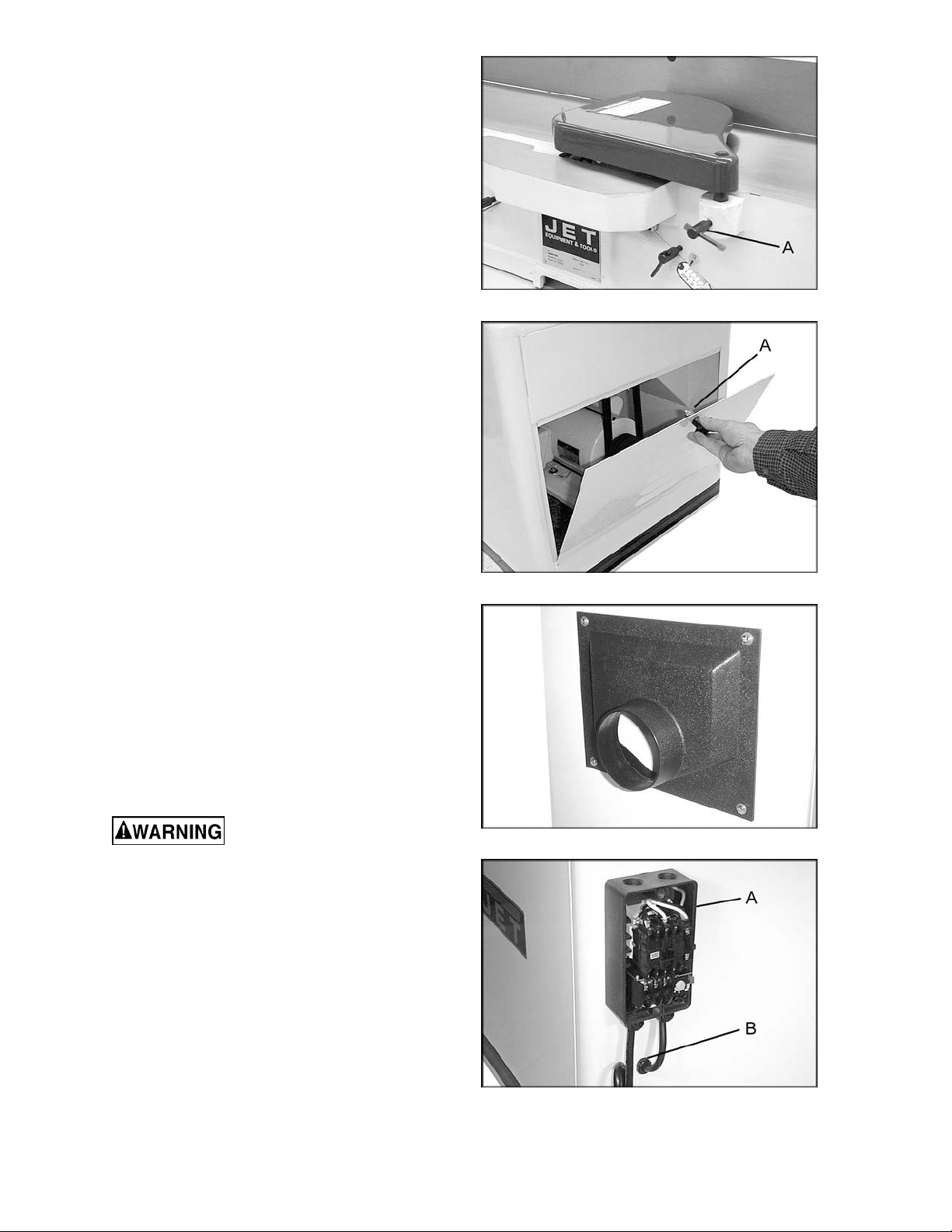
Installing Bed to Stand
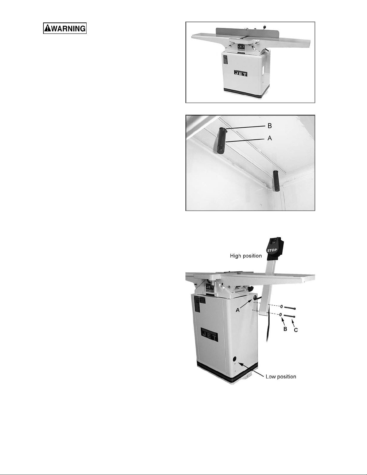
1. Use an assistant or hoist mechanism to
place bed assembly on top of stand. Be
sure identifi cati on label on t he bed fac es the
same direction as the label on the stand
(Fig. 1).
2. Line up two holes i n top of stand with holes
in bed assembl y by viewing through acces s
door in stand.
3. Attach bed assembl y to stand with two 3/8"
lock bolts and l ock washers (Fig. 2). Hand
tighten only at t his tim e.
4. Line up thir d hole in stand with hole in bed
assembly by viewing t hr ough dust c hute.
Figure 1
5. Install third 3/8" lock bolt and lock washer
through dust chute t o secure bed to stand.
6. Tighten all three mounting bolt s with 14mm
wrench.
Installing Pedestal Switch (JJ-8HH only)
Referring to Fi gur e 3:
1. The switch may be installed in either high
position or l ow position to suit the operat or.
Slide the connection plug through the
opening (A) and secure the pede stal switch
using two 5/16”x3” screws (C) and 5/16” flat
washers (B).
2. Connect the plug from the pedestal switch
to the motor plug inside t he c abinet.
Figure 2
Figure 3
8
Page 9
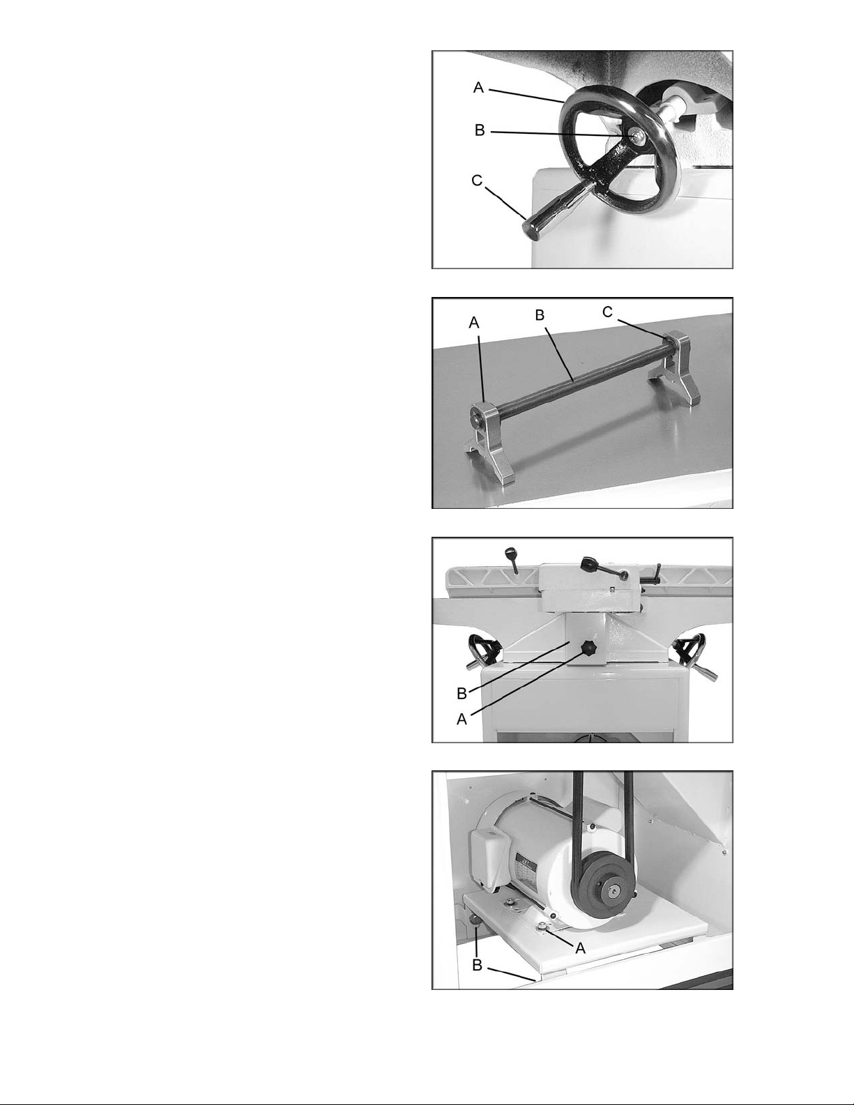
Installing Handwheels
1. Remove protective tape from shaft, and
remove screw and washer.
2. Press handwheel (A, Fig. 4) onto shaft,
aligning the keyway with the key. If
necessary, use a hammer with a block of
wood to tap the hand wheel complet ely onto
the shaft.
3. Re-install screw and washer (B, Fig. 4).
4. Mount handl e ( C, Fig. 4) onto handwheel.
Assembling Knife-Setting Gauge (JJ8CS only)
Place the t wo ba se s (A, Fig. 5) ont o eac h end of
the bar (B, Fig. 5). Snap the four E-rings (C,
Fig. 4) into the grooves on the bar as shown,
one E-ring on each si de of a base.
Installing V-Belts
Figure 4
1. Disconnect the machine from the power
source, unplug.
2. Remove the lock knob (A, Fig. 6) and belt
guard (B, Fig. 6).
3. Place v - belts onto cutterhead pul ley grooves
and through opening i n st and.
4. Pull v-belts down and place onto motor
pulley (Fig. 7). If necessary, loosen the
mounting screws (A, Fig. 7) and slightly lift
motor. Re-tighten the screws when belt is
placed.
5. Check to make sure that motor pulley and
cutterhead pulley are vertically aligned and
the v-belt does not contact the sides of the
opening in the base. If the pulleys are not
aligned, loosen t he screws (A, F ig. 7) on the
motor base and sli de the m otor unt il the belt
is aligned. Re-tighten screws.
6. The v -belt i s properly tensioned when f inger
pressure on the belt half way between the
two pulleys cau se s 1/2" deflection. If the belt
is too loose, loosen the lower screws (B,
Fig. 7) on the mounting plate and push
down on the plate. When belt tension is
correct, re-tighten screws.
Figure 5
Figure 6
7. After two hours of operation, check belt
tension again. Re-t ensi on if necessary.
8. Re-install belt guard and lock knob.
Figure 7
9
Page 10
Installing Cutterhead Guard
Orient guard (Fig. 8) in proper position and
insert post int o hole i n table. Tighten l ock screw
(A, Fig. 8) .
Installing Access Door
Install access door by placing bottom of panel
into access in stand and fastening by turning
latch ( Fig. 9) .
If the access door latch need s adju st ment:
1. Remove the acc ess door from the stand.
2. Loosen t he hex lock nut (A, Fig. 9). Rotate
the latch a quar ter turn clockwise to ti ghten
and countercl oc k wise to loosen.
3. Tighten the lock nut (A, Fig. 9).
4. Re-install the access door.
Installing Dust Chute
Attach the dust chute (Fi g. 10) t o the stand wit h
four screws and four flat washers, through the
pre-tapped holes i n the stand.
Figure 8
Figure 9
Electrical Connections
Electrical connections must
be made by a qualified electrician in
compliance with all relevant codes. This
machine must be properly grounded to help
prevent electrical shock and possible fatal
injury.
Model JJ-8CS: Rem ove the cover of the switch
box (A, Fi g. 11) and mount the box to the right
side of the stand using t he two scre ws prov i ded.
Insert the motor leads through the hole in the
stand as shown, and i nsert a grommet (B, Fig.
11).
Consult the wiri ng diagram insi de the switc h box
cover. The diagram is also on page 30 of this
manual.
Figure 10
Figure 11
10
Page 11

The JJ-8CS and JJ-8HH jointers are rated at
230V, single phase only. Confirm that the
power at the source is compatible with the
jointer bef ore inserting plug into the outl et. The
jointer is designed to be used with a plug and
outlet similar to that shown in Fig. 12.
Important: Make certain the receptacle in
question is properly grounded. If you are
not sure, have a regi stered electrician check
the receptacl e.
Extens ion Cords
Make sure the rating of the extension cord is
suitable for the amperage listed on the
machine’s motor plate. An undersize cord will
cause a drop in line volt age resulting in loss of
power and overheat ing.
Figure 12
Recommended Extension Cord Gauges (AWG)
Extension Cord Length in Feet *
Amps
25 50 75 100 150 200
< 5 16 16 16 14 12 12
Use the chart i n F igur e 13 as a gener al gui de i n
choosing the c orrect size cord. If in doubt, use
the next heavi er gauge. The smaller the gauge
number, the heavier the cord.
Adjustments
90° Fence Adjustment
Note: whenever making an adjustment to the
fence, lift the fence up slightly after rel easi ng the
lock handle to av oid scratching the table.
1. Set infeed table to the same height as the
outfeed tabl e.
2. Mov e the fence by releasing l ock handle (A,
Fig. 14) and pushing the fence assembly
until it overlaps the tables.
3. Adjust the f ence t o a 90
lock handle (B, Fig. 14), pulling up on
handle (C, Fig. 14), and re-tightening lock
handle (B, Fig. 14).
° angle by releasi ng
5 to 8 16 16 14 12 10 NR
8 to 12 14 14 12 10 NR NR
12 to 15 12 12 10 10 NR NR
15 to 20 10 10 10 NR NR NR
21 to 30 10 NR NR NR NR NR
*based on li miting the lin e vol tage drop to 5V at 15 0% of th e
rated amp eres.
NR: Not Recommended.
Figure 13
Figure 14
4. Place a combination square on the infeed
table. (Fig. 15)
5. If fence is not square to t able, release lock
handle (B, Fig. 14), loosen nut (D, Fig. 14),
and turn bolt (E, Fig. 14) until fence is
square to table.
6. Ti ghten nut (D, Fig. 14) t o retain the setting.
Tighten loc k handl e ( B, Fig. 14).
Figure 15
11
Page 12

45° Fence Adjustment
Note: Whenever making an adjustment to the
fence, lift the fence up slightly after rel easi ng the
lock handle to av oid scratching the table.
1. Loosen lock handl e (A, Fig. 16) . Move the
stop plate (B, Fig. 16) out of the way and
position the fence at the 45
sure the fence sits agai nst the stop bolt (C,
Fig. 16).
2. Place a combinati on square (D, Fig. 16) on
the fence and table to confirm a 45
3. To adjust, l oosen lock nut (E, Fi g. 16), turn
bolt (C, Fig. 16) until a 45
obtained, and tighten lock nut (E, Fig. 16).
Tighten loc k handl e ( A, Fig. 16).
° angle. Make
° setting.
° angle is
Leveling Outfeed Table to Cutterhead Knives
Figure 16
Machine should be
disconnected from power source at this
time! Cutt erhead blades are extremely sh arp!
Use caution when hands are near the
cutterhead!
For most jointi ng operations, the surface of the
outfeed tabl e must be level wit h the knife ti ps of
the cutterhead at their highest point of
revolution. The knife tips must project equally
from the cutterhead.
The outfeed table and cutterhead are adjusted
at the factory and should not r equire adjustment.
1. On the JJ-8CS Jointer, carefully number
each blade with a magic marker to make
them easier to differentiate.
2. Rotate the cutterhead by turning the
cutterhead pulley and determine the 12
o’clock position of knife number one (or a
knife insert on the JJ-8HH model). The 12
o’clock posit ion is the highest poi nt a blade
will reach in the c utti ng ar c.
3. Loosen table lock screw (A, Fig. 17) and
raise the outf eed table t o the height of blade
number one by turning handwheel (B, Fig.
17). Counter-clockwise will cause the
outfeed tabl e to raise. Clockwise will cause
the outfeed table to lower.Set a straight
edge (C, Fig. 17) on the outf eed table and
across the cutt er head.
4. Position of the table and straight edge
should look like Figure 18. Use care when
handling the straight edge near the blades
so as not to damage them.
Figure 17
Figure 18
12
Page 13

5. When the outfeed table and blade number
one (or knife insert) are the same height,
tighten table lock screw.
After t he outf eed tabl e has been set, t he JJ-
8HH will need no further adj ustments to the
cutterhead – ski p steps 6 thr ough 9 below.
The JJ-8CS must have its knives parallel
with the outf eed table. Proceed as follows:
6. Bring the straight edge forward to the front
of the outf eed table and confi rm that blade
number one is at the same height at the
front of t he table as it is at the back of t he
table.
7. If blade is higher or lower at one point,
slightly loosen five screws (A, Fig. 19) by
turning clockwise as v iewed f rom the inf eed
table.
8. Place the knif e sett ing gauge ( B, Fi g. 19) on
the cutterhead over the blade. Continue
loosening the five screws until the springs
push the knife up into contact with the
gauge. Alter nately tighten the five screws to
hold each blade in plac e.
Figure 19
9. Repeat this process with blades two and
three. The outfeed table and cutterhead
knives are correc tly adjusted when all t hree
blades are paral lel to the outfeed t able and
all three bl ades are set at the same height in
the cutter head.
After the outfeed table has been set at the
correct height, do not change it except for
special operat ions or after replacing the knives.
If the outfeed table is set too high, a curved
finished surfac e r esul ts. (Fig. 20)
If the outfeed table is set too low, gouging
results at the end of the c ut. (Fig. 21)
Figure 20
Figure 21
Figure 22 illustrates the outfeed table at the
correct height .
Figure 22
13
Page 14

Removing and Replacing Knives (JJ8CS only)
Disconnect t he machine from
the power source before making any
adjustment or repair. All knife lock bolts
must be firmly tightened or risk ejection of
the knife(s) and lo ck bar fr om the cutterhead!
Failure to compl y may cause seri ou s injury!
1. Disconnect machine from power source.
2. Remove blade guard by loosening lock
screw (A, Fig. 23) and lifting up on blade
guard. Caution: blades are sharp! Use
great care when hands are around blade
area!
3. Loosen the fiv e lock screws (Fi g. 24). Note:
Loosen screws by turning in a clockwise
direction as viewed from the infeed table.
Carefully r emove the knife (A, Fig. 25), and
the lock bar with screws (B, Fig. 25).
Repeat for the other two blades.
4. Bef ore assembly, clean all parts thor oughly
and clear cut terhead knife slots of any dust
or debris.
5. Insert knife into the cutterhead channel
making sure it f aces the proper direction.
Figure 23
Figure 24
6. Insert lock bar and screws and tighten to
hold in place. Blades are set at the proper
height when the top of the blade is 1/16"
above the cutterhead.
7. Repeat for other two blades.
8. To set the kniv es to the outf eed tabl e and to
the same height in the cutterhead, see
section titled “Leveling Outfeed Table to
Cutterhead Kniv es” found on page 12 of t his
manual.
Replacing or Rotating Knife Inserts (JJ-8HH only)
The knife inserts on the model JJ-8HH Jointer
are four-sided. When dull, simply remove each
insert, rotate it 90° for a fresh edge, and reinst a ll it.
Use the two provi ded star point screwdriv ers to
remove the knife insert screw. See Figure 26.
Use one of the screwdrivers to help hold the
cutterhead i n position, and the ot her to remove
the screw. It is advisabl e to rotate all inserts at
the same time to maintain consistent cutting.
However, if one or more knife insert s develops a
nick, rotate only those inserts that are affect ed.
Figure 25
Figure 26
14
Page 15

Each knife insert has an etched referenc e mark
so that you can keep track of t he r otati ons.
IMPORTANT: When removing or rotating
inserts, clean saw dust from the screw, the
insert, and the cutterhead platform. Dust
accumulation between these elements can
prevent the insert from seating properly, and
may affect the quali ty of the cut.
Before installing each screw, lightly coat the
screw threads wit h m achine oi l and wi pe off any
excess.
Securely tighten each screw which holds the
knife inserts before operating the planer!
Make sure all knife insert
screws are tigh ten ed secu rely. Loo se inserts
can be propelled at high speed from a
rotating cutterhead, causing injury.
Gib Adjustment
After a period of use, the gibs may become
loose and need adjusting:
1. Loosen three loc k nuts (A, Fig. 27) and gib
lock screw (B, Fig. 27)
2. Tighten each set screw 1/4 turn starting at
the bottom and working up. If a 1/4 turn
does not remove all play, take another 1/4
turn. Repeat a 1/4 turn at a time for all three
set screws until play is removed.
Figure 27
3. Tighten lock screw (B, Fig. 27) and lock nuts
(A, Fig. 27).
Operation
Keep all gu ards in place an d
in adjust ment at all times durin g the cutting
procedure! Keep hands away from the
cutterhead ! Do not pass hand s di rectl y over
the cutterhead! The use of push sticks
and/or handle pads are highly recommended
when using the jointer! Failure to comply
may cause serious injury!
Jointing cuts or edge jointing are made to
square an edge of a workpi ece. The work piece
is positi oned on t he joi nt er with t he narr ow edge
of the workpiece on the infeed table and the
major flat surface of the workpiece against the
fence (Fig. 28).
Planing cuts are similar. The major surface of
the workpiece is placed on the table with the
narrow edge of the workpi ece against the fence
(Fig. 29).
Figure 28
Figure 29
15
Page 16

For jointi ng and planing cuts pressure is directed
three ways; into the fence to ensure a square
cut, forward to advance the stock, and
downward to avoid c hatt er and v ibr ation.
For jointi ng when the materi al is higher t han the
fence, the left hand applies pressure into the
fence and down toward t he table while t he right
hand pushes forward f rom behind. Be sure to
keep the right hand high up on the material.
(Fig. 28)
For jointi ng materi al that i s lower than t he fence,
use push sticks to protect the hands. For
planing, use handle pads. (Fig. 29) Never
place the right hand on the trailing edge of
the material . Hand p lacement on the trailin g
edge of the mat erial may cause the hand to
come into contact with th e bl ade.
Feed work from right to left at a steady,
moderate speed. If you feed the material too
slowly, the wood wil l burn in places. If you feed
the material too quic kly, ridges will appear i n t he
finished surfac e.
Jointing Warped Material
If the work to be jointed is cupped or warped,
take light, repeti tive cuts until the surface is fl at.
Forcing the material flat against t he table will still
leave a warped pi ece after the cuts hav e been
made.
Never joint any material
shorter th an eight inches! The material may
tip into the jointer’s throat and be kicked
back! Avoid jointing thin material which
could become jammed under the fence or
blade guard! Failure to comply may cause
serious injury!
Direction of Grain
Feed the material with of the grain to avoid
tearout (Fig. 30). If the direction of the grain
changes somewhere in the board, try reducing
depth of cut and slow the feed speed down to
avoid tearout. If results still aren’t satisfactory,
turn the materi al around and try feedi ng through
the other way.
Bevel Cut
To cut a bevel, lock the fence at the desired
angle and run the m at erial through, pressing t he
work firmly against the fence and tables (Fig.
31). Sever al passes may be necessary f or the
desired result.
Figure 30
Figure 31
16
Page 17

Taper Cut
Taper cuts require the
removal of the cutterhead guard. Use
extreme caution wh en making taper cuts and
replace the guard immediately
completion! Failure to comply may cause
serious injury!
One of the most useful jointer operations is
cutting an edge to a t aper. Thi s method can be
used on a wide vari ety of work; tapered legs of
furniture is a common example.
Instead of laying the piece down on the infeed
table, lower the forward end of the work onto the
outfeed table. Use caution, however, as the
piece will span the knives, and they will take a
“bite” from the work with a t endenc y to kick bac k
unless the piece is held firmly. Push the work
forward as in ordinary jointing. The eff ect is to
plane off all the st ock i n fr ont of the kniv es to an
increasing dept h, leaving a tapered surface.
The ridge left by the knives when starting the
taper may be r emoved by taki ng a very light cut
in the regul ar joi nting procedure, with the i nfeed
table raised to it s normal posi tion.
Practice i s requir ed in t hi s operati on. B eginner s
are advised to make trial cuts with scrap
material.
after
Rabbet Cut
Rabbeting requires the
removal of the cutterhead guard. Use
extreme cautio n when making rabb eting cuts
and replace the guard immediately after
completion!
serious injury!
Note: Rabbet cuts are not applicable with the
Model JJ-8HH Jointer with helical head.
1. Adjust the fence so that the distance
between the end of t he knives and fence is
equal to the width of the r abbet (Fig. 32).
2. Lower the infeed table an amount equal to
the depth of the rabbet. If the rabbet is quit e
deep, it m ay be necessary to cut i n two or
more passes.
3. In that ev ent, the table is lowered an amount
equal to about half the depth of the rabbet
for the first pass, then lowered again to
proper depth to com plete the cut.
Failure to comply may cause
Figure 32
17
Page 18
Maintenance
7. Take the same amount of passes for all
three blades.
Lubrication
1. Use a good grade of light grease on the
steel adjusti ng screws located in the raising
and lowering mechanisms of the work
tables.
2. Occasionally, apply a few drops of light
machine oil to the gibs. This permits the
tables to slide f r eely .
3. The cutterhead ball bearings are lifetime
lubricated and need no further care.
Blade Care
Blades are extremely sharp!
Use caution when cleaning or changing.
Failure to compl y may cause seri ou s injury!
When gum and pitch collect on the blades,
carefully r emove with a strong solv ent. Failure
to remove gum and pit ch build-up may result in
excessiv e fric tion and overheating.
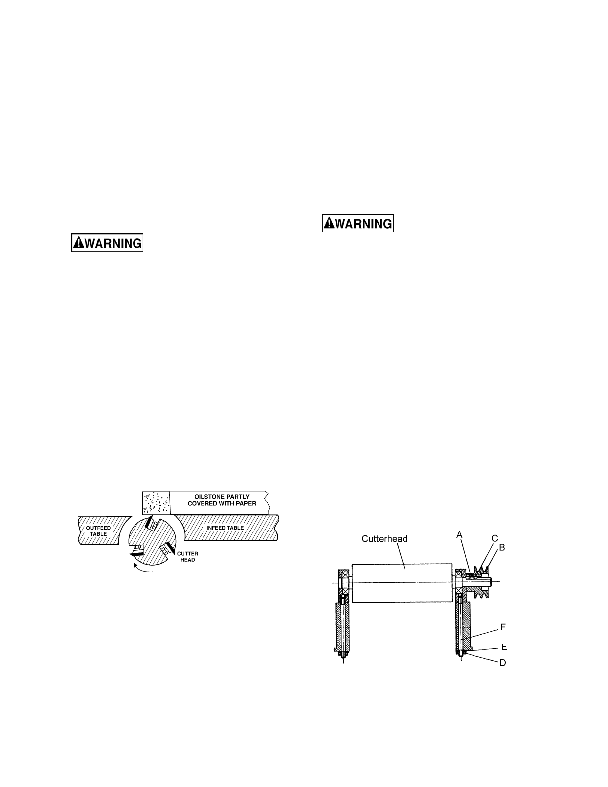
Sharpening the Knives (JJ-8CS only)
When blades becom e dull, touch up blades.
1. Disconnect the machine from the power
source.
2. Remove the fence, blade guard and belt
cover.
3. To protect the infeed table from scratches,
partially cover the sharpening stone with
paper. (Fig. 33)
When the blades hav e been sharpened, if they
still are not cutting efficientl y, trying to touch up
the blades fur ther will only cause the formation
of a second bev eled edge. When this starts to
happen, it is tim e to replace bl ades with another
set.
It is recommended to keep a second set of
blades on hand so that they may be installed
while the first set is being professionally
sharpened.
Cutterhead Removal
Bl ades in the cutterh ead are
sharp! Use extreme caution when handling
the removal of the cutterhead. Failure to
comply may cause seriou s injury!
The entire cutterhead assembly may be
removed for cleaning or for bearing and blade
replacement . Some woodworkers keep a spare
cutterhead with replacement blades should the
original c utt er head have to be repaired.
To remove the cutterhead (including bearings,
studs, and housing) from the base casting:
1. Disconnect the machine from the power
source.
2. Remove the fence assembly, cutterhead
guard, and belt guard.
3. Remove the v-belt from the cutterhead
pulley.
4. Loosen set screw (A, Fig. 34) using a hex
wrench and remove the cutterhead pulley
(B, Fig. 34) and key (C, Fig. 34).
Figure 33
4. Lay the stone on the infeed table.
5. Lower the infeed table and turn the
cutterhead by t urning the cutter head pulley.
The infeed t able hei ght is set properl y when
the stone’s surface is flush with the knife
bevel.
6. Keep the cutterhead from rotating by
grasping the cutterhead pulley while slidi ng
the stone back and forth across the table.
5. Remove nut s (D, Fig. 34) and lock washers
(E, Fig. 34).
Figure 34
18
Page 19

6. Lif t assembly str aight up. Studs (F, Fig. 34)
will still be attac hed to the bearing housings.
and the bearing housings of saw dust and
grease so that they seat pr oper ly.
7. Before replacing the cutterhead back into
the casting, thoroughly clean the “saddle”
8. To re-install the cutterhead, reverse the
above steps.
Troubleshooting
Trouble Probable Cause Remedy
Finished stock i s
concave on the end.
Back side of fi nished
stock is thicker than
the front side.
Stock is concave in
the middle.
Both ends of fi nished
stock are cut deeper
than the middl e.
Infeed or outfeed
tables are loose.
Knife tip is higher than outfeed table.
Outfeed table is higher than knife tip.
Table flatness should be chec k ed with
a machinist’s square.
Ends of tables are hi gher than middle.
Loose gib. Tighten gibs.
One blade set higher t han the others. Readjust blades
Raise outfeed table so it is level with
knife tip.
Adjust outfeed table so it is level with
knife tip.
Adjust the screws below the t able to
raise the table ends.
Raise table ends with adjustment
screws below tables.
Ripples on planed
surface.
Kickbacks
Excessive motor
noise.
Motor fails to develop
full power or stalls.
Motor starts slowly or
fails to come to full
speed.
Feeding wood too fast. Feed wood more slowly.
Cutting blades are set t oo high above
outfeed tabl e, or they m ay not be
level with outfeed table. (JJ-8CS)
Motor
Pulley set screw is loose. Tighten set screw.
Circuit ov erl oaded with lights, tools,
etc.
Undersize wires or cir c uit too long.
Voltage too low.
Fuses or circuit br eak er s do not hav e
sufficient c apaci ty.
Motor
Belt tension t oo tight. Adjust belt t ensi on.
Bad start capacit or . Replace start c apaci tor.
Readjust blades (JJ- 8CS ) .
Have motor check ed by a qualified
repair station.
Do not share the circuit .
Increase wire sizes, or reduc e length
of wiring.
Request voltage check from the
power company.
Have a qualifi ed elect ri c ian install
proper size fuses or cir c uit breakers.
Have motor check ed by a qualified
repair station.
19
Page 20

Replacement Parts
Replacement par ts are li sted on the f ollowing page s. To order parts or reac h our servi ce depar tm ent, call
1-800-274-6848, Mon day t hrough Fr iday (see our web sit e f or busi ness hours, www.j ett ool s.com). Havi ng
the Model Num ber and S eri al Num ber of y our machi ne avail abl e when you cal l will allow us to serve you
quickly and acc ur ately.
20
Page 21

Fence Assembly (all models)
Parts List – Fence Assembly (all models)
Index No. Part No. Description Size Qty
1 ............... JC-F01 .....................Fence Body ........................................................................................... 1
2 ............... JC-F02 .....................Fence Link............................................................................................. 1
3 ............... TS-0051061 .............Hex Head Screw ................................................5/16”-18 x 1-1/4” ......... 1
4 ............... TS-0561021 .............Nut .....................................................................5/16 ”-18 ...................... 1
5 ............... JC-F03 .....................Fen ce Bracket ....................................................................................... 1
6 ............... JC-F04 .....................Bolt........................................................................................................ 2
7 ............... JC-F05 .....................Bo lt.....................................................................3/8”-16........................ 4
8 ............... TS-0561031 .............Nut .....................................................................3/8” ............................. 4
9 ............... JC-F06 .....................Locking Link .......................................................................................... 1
10 ............. JC-F07 .....................Joint P late ............................................................................................. 1
11 ............. 5C-E051 ..................Flat Head Bolt.....................................................5/16”-18 x 1-1/2” ......... 1
12 ............. JC-F08 .....................Screw .................................................................................................... 1
13 ............. TS-0207081 .............Socket Head Cap Screw .....................................1/4”-20 x 1-1/2 ” ........... 2
14 ............. TS-0207021 .............Socket Head Cap Screw .....................................1/4”-20 x 1/2” .............. 1
15 ............. TS-0050061 .............Nut .....................................................................1/4”-20........................ 2
16 ............. JC-F09 .....................Pin......................................................................5x50 ........................... 1
17 ............. JC-F10 .....................Stop Block ............................................................................................. 1
18 ............. TS-0561052 .............Nut .....................................................................1/2”-20........................ 2
19 ............. JC-F11 .....................Locking Bolt w/Handle ........................................................................... 1
20 ............. TS-0680061 .............Flat Wash er ........................................................1/2”............................. 2
21 ............. 6296081...................Nut ........................................................................................................ 1
22 ............. JC-F14 .....................Eccentric Shaft ...................................................................................... 1
23 ............. JC-F15 .....................Handle................................................................................................... 2
24 ............. LA-H34 ....................Knob ..................................................................................................... 2
25 ............. 6296083...................Hex Nut ..............................................................1/2”-12........................ 2
26 ............. JC-F16 .....................Eye Bolt ................................................................................................. 1
21
Page 22
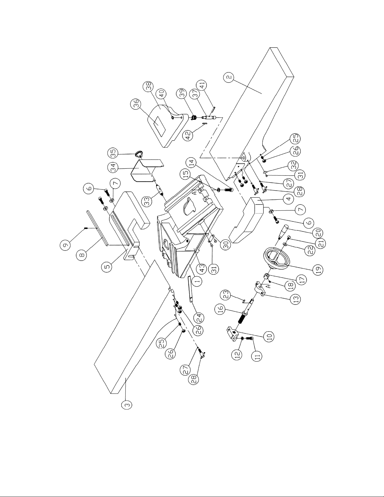
Bed Assembly (all models)
22
Page 23

Parts List – Bed Assembly (all models)
Index No. Part No. Description Size Qty
1 ............... JC-T01 .....................Base ...................................................................................................... 1
2 ............... JC-T02 .....................Fro n t Ta b le ............................................................................................ 1
3 ............... JC-T03 .....................Rear Table ............................................................................................ 1
4 ............... JC-T04 .....................Rabbeting Arm ...................................................................................... 1
5 ............... JC-T05 .....................Tab le Bracket ........................................................................................ 1
6 ............... TS-0060071 .............Cap Screw..........................................................3/8”-16 x 1-1/2” ........... 4
7 ............... TS-0720091 .............Lock Was h e r ......................................................3/8”............................. 4
8 ............... JC-T07 .....................Ke y.....................................................................9 .5 x 9.5 x 273 ............ 1
9 ............... 5F-E153 ...................Spring Pin...........................................................4 x 16 ......................... 1
10 ............. JC-T08 .....................Feed Screw Bracket .............................................................................. 2
11 ............. TS-0060061 .............Socket Head Cap Screw .....................................3/8”-16 x 1-1/4 ” ........... 4
12 ............. TS-0720091 .............Lock Washer ......................................................3/8”............................. 4
13 ............. JC-T09 .....................Bracket .................................................................................................. 2
14 ............. JJ8HH-214 ...............Cap Screw..........................................................1/2”-12 x 1-1/2” ........... 4
15 ............. TS-0720111 .............Lock Washer ......................................................1/2”............................. 4
16 ............. JC-T10 .....................Feed Screw ........................................................................................... 2
17 ............. JC-T11 .....................Ring ...................................................................................................... 2
18 ............. TS-0267041 .............Set Screw ...........................................................1/4”-20 x 3/8” .............. 4
19 ............. PA-C42 ....................Handwheel ............................................................................................ 2
20 ............. JC-T12 .....................Handle................................................................................................... 2
21 ............. 5C-D003 ..................Pan Head Machi ne S crew ..................................5/16”-18 x 1/2” ............ 2
22 ............. TS-0680031 .............Flat Wash er ........................................................5/16” ........................... 2
23 ............. F5-G107 ..................Key.....................................................................5 x 5 x 22 ................... 2
24 ............. JC-T13 .....................Gib ...................................................................................................... .. 2
25 ............. TS-0270091 .............Set Screw ...........................................................5/16”-18 x 1” ............... 6
26 ............. TS-0561021 .............Hex Nut ..............................................................5/16”-18 ...................... 6
27 ............. 5I-D003 ....................Ball ........................................................................................................ 2
28 ............. JC-T15 .....................Stop Handle .......................................................................................... 3
30 ............. JC-T16 .....................Scale ....................................................................................................
31 ............. 5F-H051...................Rivet ...................................................................................................... 7
32 ............. JC-T17 .....................Depth Pointer ........................................................................................ 1
33 ............. PA-C49 ....................Guard Bolt ............................................................................................. 1
34 ............. JC-T18 .....................Pulley Cover .......................................................................................... 1
35 ............. PA-C53 ....................Nut ........................................................................................................ 1
36 ............. JC-T19 .....................Warning Label ....................................................................................... 1
37 ............. JC-T20 .....................Guard Shaft ........................................................................................... 1
38 ............. JC-T21 .....................Cutterhead Guard .................................................................................. 1
39 ............. JC-T22 .....................Spring.................................................................................................... 1
40 ............. 5F-A002 ...................Retaining Ring ....................................................STW-11 ...................... 1
41 ............. 5F-E208 ...................Spring Pin...........................................................5 x 28 ......................... 1
42 ............. 5F-E258 ...................Spring Pin...........................................................6 x 36 ......................... 1
43 ............. JJ8CS-ID .................I.D. Label ............................................................................................... 1
................. JJ8HH- ID .................I.D. Label ............................................................................................... 1
. 1
23
Page 24
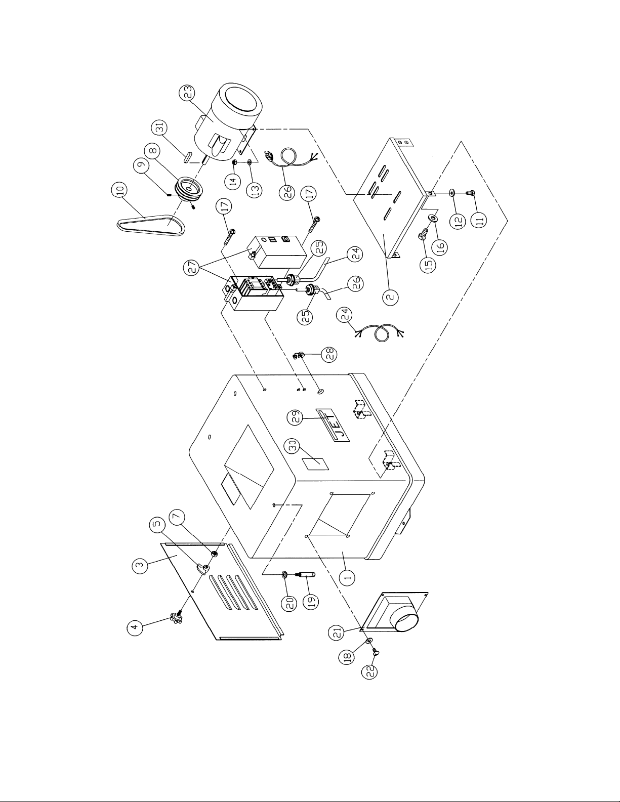
Stand and Motor Assembly (JJ-8CS only)
24
Page 25

Parts List – Stand and Motor Assembly (JJ-8CS only)
Index No. Part No. Description Size Qty
1 ............... JC-M01 W .................Stand .................................................................................................... 1
2 ............... JC-M02 W .................Motor Mount .......................................................................................... 1
3 ............... JC-M03 W .................Cover .................................................................................................... 1
4 ............... JC-M04 ....................Screw .................................................................................................... 1
5 ............... JC-M05 ....................Key........................................................................................................ 1
7 ............... TS-0561031 .............Hex Nut ..............................................................3/8”-16........................ 1
8 ............... JC-M06 ....................Motor Pulley .......................................................................................... 1
9 ............... TS-0271071 .............Set Screw ...........................................................3/8”-16 x 3/4” .............. 2
10 ............. VB-M52....................V-Belt .................................................................................................... 2
11 ............. TS-0081031 .............Hex Head Screw ................................................5/16”-18 x 3/4” ............ 4
12 ............. TS-0680031 .............Flat Wash er ........................................................5/16” ........................... 4
13 ............. TS-0680031 .............Flat Wash er ........................................................5/16” ........................... 4
14 ............. TS-0561021 .............Hex Nut ..............................................................5/16”-18 ...................... 4
15 ............. JJ8HH-315 ...............Hex Head Screw ................................................1/2 ”- 1 2 x 1” ................. 4
16 ............. TS-0680061 .............Flat Wash er ........................................................1/2”............................. 4
17 ............. JCS10-079C ............Screw .................................................................3/16”-UNC x 3/4” ........ 2
18 ............. TS-0680021 .............Flat Wash er ........................................................1/4”............................. 4
19 ............. JC-M07 ....................Lock Bolt ............................................................3/8”-16........................ 3
20 ............. TS-0720091 .............Lock Washer ......................................................3/8”............................. 3
21 ............. JC-M03 ....................Dust Chute ............................................................................................ 1
22 ............. TS-0813032 .............Pan Head Screw ................................................1/4”-20 x 1/2” .............. 4
23 ............. JJ8-917W ................Motor ..................................................................2HP, 1Ph .................... 1
24 ............. JJ8-918 ....................Motor Cord ............................................................................................ 1
25 ............. JJ8-919 ....................Strain Relief ........................................................................................... 2
26 ............. JJ8-920 ....................Power Cord ........................................................................................... 1
27 ............. JJ8CS-327 ...............Switch ................................................................................................... 1
28 ............. JJ8-923 ....................Strain Relief ........................................................................................... 1
29 ............. PG-M02 ...................JET Label .............................................................................................. 1
30 ............. JC-T23 .....................Warning
31 ............. 5FK-C13 ..................Key.....................................................................5x5x35 ....................... 1
................. JJ8CS-HK ................Hardware Kit (not shown) ........................................................................
Label ....................................................................................... 1
25
Page 26

Stand and Motor Assembly (JJ-8HH only)
26
Page 27

Parts List – Stand and Motor Assembly (JJ-8HH only)
Index No. Part No. Description Size Qty
1 ............... JJ8HH- 301 ...............Stand .................................................................................................... 1
2 ............... JC-M02 W .................Motor Mount .......................................................................................... 1
3 ............... JC-M03 W .................Cover .................................................................................................... 1
4 ............... JC-M04 ....................Knob Screw ........................................................................................... 1
5 ............... JC-M05 ....................Door Latch............................................................................................. 1
7 ............... TS-0561031 .............Hex Nut ..............................................................3/8”-16........................ 1
8 ............... JC-M06 ....................Motor Pulley .......................................................................................... 1
9 ............... TS-0271031 .............Set Screw ...........................................................3/8”-16x3/8” ................ 2
10 ............. VB-M52....................V- Belt ...............................................................M-52 ........................... 2
11 ............. TS-0081031 .............Hex Cap S cr e w ..................................................5/16 ” -1 8 x3/4 ” .............. 4
12 ............. TS-0680031 .............Flat Wash er ........................................................5/16” ......................... 12
14 ............. TS-0561021 .............Hex Nut ..............................................................5/16”-18 ...................... 4
15 ............. JJ8HH-315 ...............Hex Bolt .............................................................1 /2 ” -1 2 x1 ” ................... 4
16 ............. TS-0680061 .............Flat Wash er ........................................................1/2”............................. 4
18 ............. TS-0680021 .............Flat Wash er ........................................................1/4”............................. 4
19 ............. JC-M07 ....................Lock Bolt ............................................................................................... 3
20 ............. TS-0720091 .............Lock Washer ......................................................3/8”............................. 3
21 ............. JC-M03 ....................Dust Chute ............................................................................................ 1
22 ............. TS-081F032 .............Screw .................................................................1/4”-20x1/2” ................ 4
23 ............. JJ8-917W ................Motor ..................................................................2HP, 1Ph .................... 1
29 ............. PG-M02 ...................JET Label .............................................................................................. 1
30 ............. JC-T23 .....................Warning Label ....................................................................................... 1
31 ............. 5FK-C13 ..................Key.....................................................................5x5x35 ....................... 1
32 ............. JJ6HH-316 ...............Cord Protector ....................................................................................... 2
33 ............. JJ6HH-315 ...............Switch Arm ............................................................................................ 1
34 ............. JPS10TS-343 ..........Main Switch ........................................................................................... 1
35 ............. TS-0208141 .............Socket Head Cap Screw .....................................5/16”-18x3” ................. 2
37 ............. JJ6HH-348 ...............Screw .................................................................M4x25 ........................ 2
38 ............. JPS10TS-342 ..........Stop Switch Face Pla te .......................................................................... 1
39 ............. TS-2171012 .............Screw .................................................................M4x6 .......................... 2
40 ............. JJ6HH-351 ...............Star Washe r .......................................................M 4 .............................. 2
41 ............. JJ6HH-352
42 ............. JPS10TS-347 ..........Switch Box ............................................................................................ 1
44 ............. JJ8HH-344 ...............Motor Cord ............................................................................................ 1
45 ............. JJ8HH-345 ...............Strain Relief ........................................................................................... 2
46 ............. JJ8HH-346 ...............Power Cord ........................................................................................... 1
47 ............. TS-0208021 .............Socket Head Cap Screw .....................................5/16”-18x1/2” .............. 2
................. JJ8HH- HK ................Hardware Kit (not shown) ...................................................................... 1
...............Switch P late ......................................................................................... 1
27
Page 28

Parts List – Cutterhead Assembly (JJ-8CS only)
Index No. Part No. Description Size Qty
1 ............... JC-C01 ....................Cutterhead ............................................................................................ 1
2 ............... JC-C02 ....................Bearing Housin g .................................................................................... 2
3 ............... 5H-A104 ..................Bearing .................................................................................................. 2
4 ............... JC-C03 ....................Cutterhead Set Bolt ............................................................................... 2
5 ............... TS-0680041 .............Flat Washer ........................................................3/8”............................. 2
6 ............... TS-0561031 .............Nut .....................................................................3/8” -16........................ 2
7 ............... PA-C05 ....................Spring.............................................................................. ...................... 6
8 ............... 708802 ....................Knife ...................................................................................................... 3
9 ............... JC-C05 ....................Knife Lock Bar ....................................................................................... 3
10 ............. JC-C06 ....................Screw .................................................................................................. 15
11 ............. JC-C07 ....................Knife Gauge Rod ................................................................................... 1
12 ............. JC-C08 ....................Knife Gauge .......................................................................................... 2
13 ............. JJ8-0013 ..................Retaining Ring ....................................................STW-9” ....................... 4
15 ............. JC-C09 ....................Machine Pulley ...................................................................................... 1
16 ............. 5F-G107 ..................Key.....................................................................5 x 5 x 22 ................... 1
17 ............. TS-0270031 .............Set Screw ...........................................................5/16”-18NC x 3/8” ....... 2
28
Page 29

Parts List – Cutterhead Assembly (JJ-8HH only)
Index No. Part No. Description Size Qty
................. JJ8HH- CA ................Cutterhead Assembly (Index # 1 thru 11) ............................................... 1
................. 1791222-4 ...............Helical Cutterhead Unit (Index # 1, 7, 8)................................................. 1
1 ............... JJ8HH- 101 ...............Helical Cutterhead ................................................................................. 1
2 ............... JC-C02 ....................Bearing Housin g .................................................................................... 2
3 ............... BB-6204VV ..............Ball Bearing ........................................................6204VV ...................... 2
4 ............... JC-C03 ....................Bolt........................................................................................................ 2
5 ............... TS-0680041 .............Flat Washer ........................................................3/8”............................. 2
6 ............... TS-0561031 .............Hex Nut ..............................................................3/8”-16........................ 2
7 ............... 1791212...................Knife Insert (set of 10) .................................................................. total 36
8 ............... JWP208HH-111 .......Knife Ins e rt Scre w ..............................................#10-32x1/2 .............. 36
9 ............... 5 F-G10 7 ..................Key.....................................................................5 x5x22 ...... ................. 1
10 ............. TS-0270031 .............Socket Set Screw ...............................................5/16”-18x3/8” .............. 2
11 ............. JC-C09 ....................Cutterhead Pulley .................................................................................. 1
12 ............. JJ6HH-113 ...............Star Point Screwdriver (not shown) ........................................................ 2
29
Page 30

Electrical Connections (JJ-8C S on ly )
Motor
BLACK
WHITE
1L2
3L2A15L3
GREEN
WHITE
BLACK
4T2
2T1
4T2
2T1
6T3
6T3
13NO
17
18
14NO
A2
9798
96 95
GREEN
GROUND
GREEN
GREEN
WHITE
BLACK
BLACK
WHITE
30
Page 31

Electrical Connections (JJ-8H H on ly )
31
Page 32

427 New Sanford Road
LaVergne, Tennessee 37086
Phone: 800-274-6848
www.jettools.com
32
 Loading...