

Page 1

Assembly and Parts Manual
JRF-14RN Deluxe Rip Fence w/Resaw
(#714101, fits 15” x 15” table)
JET
427 New Sanford Road
LaVergne, Tennessee 37086 Part No. M-714101
Ph.: 800-274-6848 Edition 2 09/2018
www.jettools.com Copyright © 2016 JET
Page 2
WARNING: This product can expose you to
chemicals including lead which is known to the State
of California to cause cancer and birth defects or
other reproductive harm. For more information go to
http://www.p65warnings.ca. gov.
WARNING: Drilling, sawing, sanding or machining
wood products generates wood dust and other
substances known to the State of California to cause
cancer. Avoid inhaling dust generated from wood
products or use a dust mask or other safeguards for
personal protection.
Wood products emit chemicals known to the State of
California to cause birth defects or other reproductive
harm. For more information go to http://www.
p65warnings. ca.gov/ wood.
Assembly
1. Disconnect the machine from the power source,
unplug.
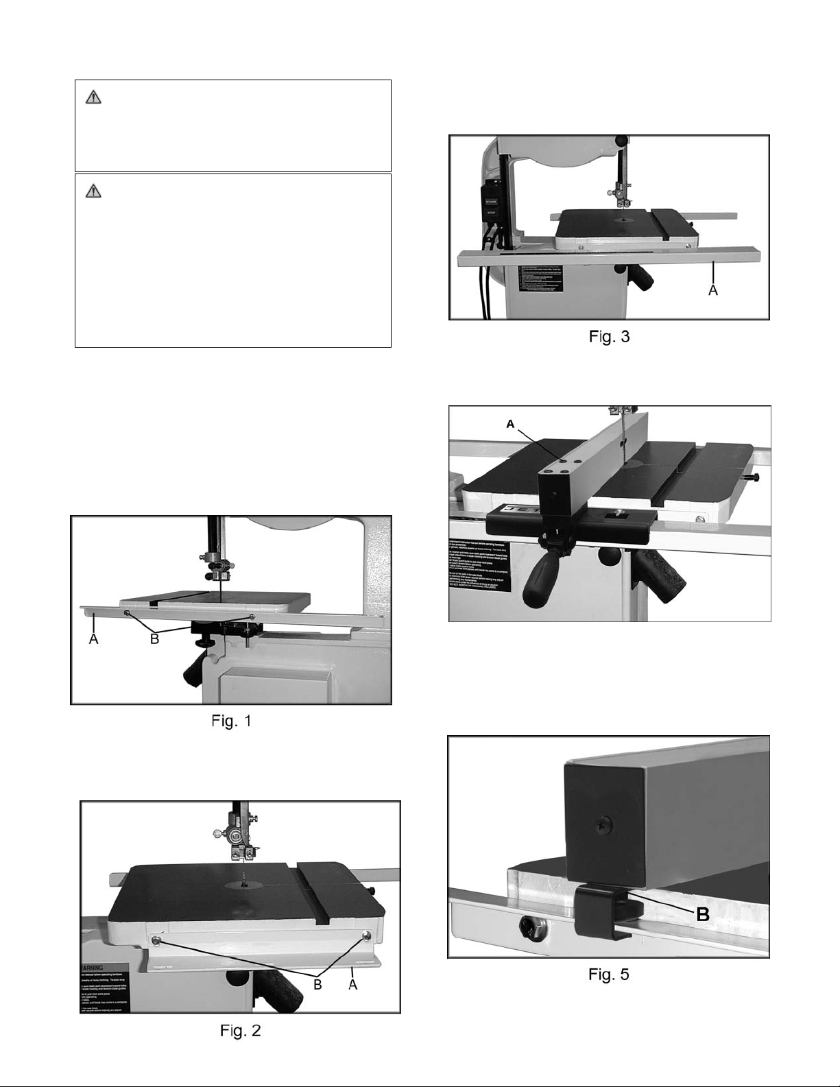
2. Mount the rear rail (A, Fig. 1) to the bandsaw table
using two M6x20 hex cap screws, two lock
washers and two flat washers (B, Fig. 1). Do not
tighten.
4. Mount the guide rail (A, Fig. 3) to the front rail
using three M6x20 hex cap screws, three lock
washers and three 1/4" flat washers.
5. Attach the fence to the fence body using four M6
socket head cap screws and four lock washers (A,
Fig. 4).
Fig 4
6. Place fence assembly onto the guide rail. The rear
hook should engage the rear rail and the pad will
slide along the rear rail, Figure 5. Use nut (B, Fig.
5) to adjust height of pad.
3. Mount the front rail (A, Fig. 2) to the bandsaw table
using two M6x20 hex cap screws, two lock
washers and two flat washers (B, Fig. 2). Do not
tighten.
2
Page 3

7. The gap between the bottom of the fence and the
table top should be the same across the entire
table.
8. The front rail, rear rail and sliding pad can be
raised or lowered to allow for an equal gap. At the
same time make sure the fence is perpindicular to
the table top (A, Fig. 6).
Fig. 6
9. Tighten front and rear rails.
10. Position the fence along the blade and tighten the
handle. To make an adjustment loosen four hex
cap bolts (A, Fig. 7) and align the fence with the
blade. Tighten bolts.
12. For resawing operations attach the post (A, Fig. 8)
to fence with the hand knob. There is a slotted hole
in the fence that will accommodate the resaw kit.
Position the post so that it is centered with the front
edge of the blade.
Fig. 8
Fig. 7
11. Check to see that the pointer (B, Fig. 7) is aligned
with the zero marking on the guide rail. If
adjustment is necessary loosen the screw that
holds the pointer in place. Adjust as necessary.
3
Page 4

JRF-14R Parts List
Index No. Part No. Description Size Qty
1 ................ 198013 .......................Lock Handle* ........................................................... ...................................... 1
2 ................ TS-1540061 ...............Hex Nut* .................................................................. M8 ................................. 1
3 ................ SG049100 ..................Flanged Hex Cap Screw.......................................... M4*6*0.8 ....................... 1
4 ................ 198006 .......................Leaf Spring .............................................................. ...................................... 1
5 ................ TS-2249402 ...............Socket Head Button Screw ..................................... M10-1.5x40 ................... 1
6 ................ 136470-1 ....................Wear Pad ................................................................ 10x28x1 mm ................. 6
7 ................ SS100250 ..................Nylon Set Screw ...................................................... M10-1.5x10 ................... 2
8 ................ 198059 .......................Pointer ..................................................................... ...................................... 1
9 ................ TS-2285502 ...............Pan Head Phillips Screw ......................................... M5x5 ............................. 1
10 .............. 198004 .......................Fixed Block .............................................................. ... ................................... 1
11 .............. F001755 .....................Lock Nut (Black) ...................................................... M10 ............................... 1
12 .............. 198140 .......................Fence Body ............................................................. ...................................... 1
13 .............. JWBS14-F01 .............JET Plaque .............................................................. 1-3/16 x 2-1/4” .............. 1
14 .............. F011270 .....................Pan Hd Phillips Tap Screw (Black) .......................... #6-20x1/2”..................... 2
15 .............. 198015 .......................Fence Cover ............................................................ ...................................... 2
16 .............. 198010 .......................Spacer Bushing ....................................................... Ø6.5x42.5 mm .............. 4
17 .............. TS-2361061 ...............Spring Washer......................................................... M6 ................................. 4
18 .............. TS-1503121 ...............Socket Head Cap Screw ......................................... M6x55L ......................... 4
19 .............. 100152 .......................Screw Knob ............................................................. ...................................... 1
20 .............. 198145 .......................Aluminum Extrusion Fence...................................... 515L x 50H mm ............ 1
21 .............. 198142 .......................Rear Hook ............................................................... ...................................... 1
22 .............. TS-2311061 ...............Hex Nut.................................................................... M6 ................................. 1
23 .............. 198012 .......................Adjust Screw............................................................ M6x20 ........................... 1
24 .............. 198092 .......................Resaw Post* ............................................................ ...................................... 1
25 .............. JWBS14-F27 .............Rear Rail.................................................................. ........ .............................. 1
26 .............. JWBS14-F24 .............Guide Rail ................................................................ ...................................... 1
27 .............. JWBS14-F23 .............Scale Label .............................................................. (inches) ......................... 1
28 .............. JWBS14-F25 .............Front Rail ................................................................. ...................................... 1
29 .............. TS-1550041 ...............Flat Washer*............................................................ M6xØ13 ........................ 7
30 .............. TS-1482041 ...............Hex Cap Screw* ...................................................... M6x20 ....... .................... 7
31 .............. TS-0720071 ...............Lock Washer* .......................................................... 1/4“................................ 5
32 .............. 2013-285 ....................End Cap................................................................... 25x50 mm ..................... 2
..................
JWBS14-HKN ...........Hardware Package (includes items marked with *) . ...................................... 1
4
 Loading...