

Page 1
This .pdf document is bookmarked
Operating Instructions and Parts Manual
DC-1200VX Series Dust Collectors
Now with
DC-1200VX with Bag Filter Kit DC-1200VX with Canister Kit
JET
427 New Sanford Road
LaVergne, Tennessee 37086 Part No. M-710701
Ph.: 800-274-6848 Revision B 07/ 2014
www.jettools.com Copyright © 2014 JET
Page 2

Warranty and Service
JET® warrant s ever y pro duct i t sell s against m anuf actu rers’ defec ts. If one of ou r tools needs ser vice or rep air, please
contact Technical Service by calling 1-800-274-6846, 8AM to 5PM CST, Monday through Friday.
Warranty Period
The general warranty lasts for the time period specified in the literature included with your product or on the official JET
branded website.
• JET products carry a limited warranty which varies in duration based upon the product. (See chart below)
• Accessories carry a limited warranty of one year from the date of receipt.
• Consumable items are defined as expendable parts or accessories expected to become inoperable within a
reasonable amount of use and are covered by a 90 day limited warranty against manufacturer’s defects.
Who is Covered
This warranty covers only the initial purchaser of the product from the date of delivery.
What is Co vered
This warranty covers any defects in workmanship or materials subject to the limitations stated below. This warranty does
not cover failures due directly or indirectly to misuse, abuse, negligence or accidents, normal wear-and-tear, improper
repair, alterations or lack of maintenance. JET woodworking machinery is designed to be used with Wood. Use of these
machines in the processing of metal, plastics, or other materials may void the warranty. The exceptions are acrylics and
other n atura l items that are made specificall y for w ood turnin g.
Warranty Limitations
Woodworking products with a Five Year Warranty that are used for commercial or industrial purposes default to a Two
Year Warranty. Please contact Technical Service at 1-800-274-6846 for further clarification.
How to Get Technical Support
Please contact Technical Service by calling 1-800-274-6846. Please note that you will be asked to provi d e pr o of of
initial p u rchase when calli ng. If a product requires furt h er inspection, the Technical Service represent a tive will explai n
and assist with any additional action needed. JET has Authorized Service Centers located throughout the United States.
For the name of an Authorized Service Center in your area call 1-800-274-6846 or use the Service Center Locator on the
JET website.
More Information
JET is constantly adding new products. For complete, up-to-date product information, check with your local distributor or
visit the JET website.
How S tate Law A pplies
This warranty gives you specific legal rights, subject to applicable state law.
Limitations on This Warranty
JET LIMITS ALL IMPLIED WARRANTIES TO THE PERIOD OF THE LIMITED WARRANTY FOR EACH PRODUCT.
EXCEPT AS STATED HEREIN, ANY IMPLIED WARRANTI ES OF MERCHANTABILITY AND FITNESS FOR A
PARTICULAR PURPOSE ARE EXCLUDED. SOME STATES DO NOT ALLOW LIMITATIONS ON HOW LONG AN
IMPLIED WARRANTY LASTS, SO THE ABOVE LIMITATION MAY NOT APPLY TO YOU.
JET SHALL IN NO EVENT BE LIABLE FOR DEATH, INJURIES TO PERSONS OR PROPERTY, OR FOR INCIDENTAL,
CONTINGENT, SPECIAL, OR CONSEQUENTIAL DAMAGES ARISING FROM THE USE OF OUR PRODUCTS. SOME
STATES DO NOT ALLOW THE EXCLUSION OR LIMITATION OF INCIDENTAL OR CONSEQUENTIAL DAMAGES, SO
THE ABOVE LIMITATION OR EXCLUSION MAY NOT APPLY TO YOU.
JET sells through distributors only. The specifications listed in JET printed materials and on official JET website are given
as general information and are not binding. JET reserves the right to effect at any time, without prior notice, those
alterations to parts, fittings, and accessory equipment which they may deem necessary for any reason whatsoever. JET
branded products are not sold in Canada by JPW Industries, Inc.
Product Listing with Warranty Period
90 Days – Parts; Consumable items; Light-Duty Air Tools
1 Year – Motors; Machine Accessories; Heavy-Duty Air Tools; Pro-Duty Air Tools
2 Year – Metalworking Machinery; Electric Hoists, Electric Hoist Accessories; Woodworking Machinery used
for industrial or commercial purposes
5 Year – Woodworking Machinery
Limited Lifetime – JET Parallel clamps; VOLT Series Electric Hoists; Manual Hoists; Manual Hoist
Accessories; Shop Tools; Warehouse & Dock products; Hand Tools
NOTE: JET is a division of JPW Industries, Inc. References in this document to JET also apply to JPW Industries, Inc., or
any of its successors in interest to the JET brand.
®
2
Page 3

Table of Contents
Warranty and Service ............................................................................................................................................ 2
Table of Contents .................................................................................................................................................. 3
Warnings ............................................................................................................................................................... 4
Introduction ............................................................................................................................................................ 5
Specifications ........................................................................................................................................................ 6
Unpacking ............................................................................................................................................................. 7
Shipping Content ................................................................................................................................................... 7
Base Units ......................................................................................................................................................... 7
Canister Filter Kit ............................................................................................................................................... 8
30 Micron Bag Filter Kit ..................................................................................................................................... 8
5 Micron Bag Filter Kit (Optional) ...................................................................................................................... 8
Base Unit Assembly .............................................................................................................................................. 9
Base .................................................................................................................................................................. 9
Motor and Fan Assembly ................................................................................................................................... 9
Connector Housing ............................................................................................................................................ 9
Cone Assembly ............................................................................................................................................... 10
Hose ................................................................................................................................................................ 10
Filter Bag Kit Assembly ....................................................................................................................................... 11
Filter Bag Installation ....................................................................................................................................... 11
Collector Bag Installation ................................................................................................................................. 11
Canister Kit Assembly ......................................................................................................................................... 12
Canister Filter .................................................................................................................................................. 12
Collector Bag ................................................................................................................................................... 12
Electrical Connections ......................................................................................................................................... 13
Turning the Machine On & Off ............................................................................................................................. 13
All Models ........................................................................................................................................................ 13
Remote Contr ol (Optional Accessory) ............................................................................................................. 13
Turning the DC-RC230 On & Off ..................................................................................................................... 13
Changing Operating Frequency ...................................................................................................................... 14
Installing the DC-RC Remote Power Con trol .................................................................................................. 14
Maintenance ........................................................................................................................................................ 15
Cleaning the Filter Bag - DC-1200VX-BK1 and DC-1200VX-BK3 .................................................................. 15
Removing the Collector Bag – DC-1200VX-BK1 and DC-1200VX-BK3 ......................................................... 15
Cleaning the Canister Filter – DC-1200VX-CK1 and DC-1200VX-CK3 .......................................................... 15
Removing the Collector Bag – DC-1200VX-CK1 and DC-1200VX-CK3 ......................................................... 15
Motor ............................................................................................................................................................... 15
Connecting the Dust Collector to a Machine ................................................................................................... 15
Grounding the Dust Collection System ............................................................................................................ 15
Parts Breakdown for the DC-1200VX Dust Collector ...................................................................................... 16
Ordering Replacement Parts ............................................................................................................................... 17
Parts List for the DC-1200VX Dust Collector ................................................................................................... 17
Canister Filter Kit (708639B) ........................................................................................................................... 19
30 Micron Filter Bag Kit (708636F) .................................................................................................................. 20
5-Micron Filter Bag Kit (708636MF) Optional Accessory ............................................................................... 21
Electrical Connections ......................................................................................................................................... 22
Wiring Diagram For 3 Phase 230/460V Dust Collector (DC-1200VX) ............................................................. 22
Wiring Diagram For Single Phase 230V Only Dust Collector (DC-1200VX) ................................................... 22
3
Page 4

Warnings
1. Read and understand the entire owner's manual before attempting assembly or operation.
2. Read and understand the warnings posted on the machine and in this manual. Failure to comply with all of
these warnings may cause serious injury.
3. Replace the warning labels if they become obscured or removed.
4. This dust collector is designed and intended for use by properly trained and experienced personnel only. If you
are not familiar with the proper and safe operation of a dust collector, do not use until proper training and
knowledge have been obtained.
5. Do not use this dust collector for other than its intended use. If used for other purposes, JET disclaims any real
or implied warranty and holds itself harmless from any injury that may result from that use.
6. Always wear approved safety glasses/face shields while using this dust collector. Everyday eyeglasses only
have impac t resista nt lenses; t he y ar e no t sa fety g lasses.
7. Before operating this dust collector, rem ove tie, rings, watches and other j ewelry, and roll sleeves up past the
elbows. Remove all loose clothing and confine long hair. Non-slip footwear or anti-skid floor strips are
recommended. Do not wear gloves.
8. Wear ear protectors (plugs or muffs) during extended periods of operation.
9. Some dust created by power sanding, sawing, grinding, drilling and other construction activities contain
chemicals known to cause cancer, birth defects or other reproductive harm. Some examples of these chemicals
are:
• Lead from lead based paint.
• Crystalline silica from bricks, cement and other masonry products.
• Arsenic and chromium from chemically treated lumber.
Your risk of exposure varies, depending on how often you do thi s type of work. To reduce your exposure to
these chemicals, work in a well-ventilated area and work with approved safety equipment, such as face or dust
masks that are specifically designed to filter out microscopic particles.
10. Do not operate this machine while tired or under the influence of drugs, alcohol or any medication.
11. Make certain the switch is in the OFF position before connecting the machine to the power supply.
12. Make certain the machine is properly grounded.
13. Make all machine adjustments or maintenance with the machine unplugged from the power source.
14. Remove adjusting keys and wrenches. Form a habit of checking to see that keys and adjusting wrenches are
removed from the machine before turning it on.
15. Keep safety guards in place at all times when the mac hine is in use. If rem oved f or m aintenance purposes, use
extreme caution and replace the guards immediately.
16. Check damaged parts. Before further use of the machine, a guard or other part that is damaged should be
carefully checked to determine that it will operate properly and perform its intended function. Check for
alignment of moving parts, binding of moving parts, breakage of parts, mounting and any other conditions that
may affect its operation. A guard or other part that is damaged should be properly repaired or replaced.
17. Provide for adequate space surrounding work area and non-glare, overhead lighting.
18. Keep the floor around the machine clean and free of scrap material, oil and grease.
19. Keep visitors a safe distance from the work area. Keep children away.
20. Make your workshop child proof with padlocks, master switches or by removing starter keys.
21. Give your work undivided attention. Looking around, carrying on a conversation and “horse-play” are careless
acts that can result in serious injury.
4
Page 5

22. Do not use the dust collector for anything except wood dust. Materials such as liquids, metal shavings, metal
dust, screws, glass, plastic or rock can cause sparks and/or damage when coming into contact with any part of
the dust collector.
23. Use recommended accessories; improper accessories may be hazardous.
24. Maintain tools with care. Follow instructions for lubricating and changing accessories.
25. Turn off the machine before cleaning. Use a brush or compressed air to remove chips or debris — do not use
your hand s.
26. Do not stand on the machine. Serious injury could occur if the machine tips over.
27. Never leave the machine running unattended. Turn the power off and do not leave the machine until it comes to
a complete stop.
28. Remove loose items and unnecessary work pieces from the area before starting the machine.
29. Never place hands near the inlet of the machine.
30. Always make certain machine is off and unplugged when making any connections to the inlet.
Familiarize yourself with the following safety notices used in this manual:
This means that if precautions are not heeded, it may result in minor injury and/or possible
machine damage.
This means that if precautions are not heeded, it may result i n serious injury or possibly even
death.
- - SAVE THESE INSTRUCTIONS - -
Introduction
This manual is provided by JET covering the safe operation and maintenance procedures for model
DC-1200VX Series Dust Collectors. This manual contains instructions on installation, safety precautions, general
operating procedures, maintenance instructions and parts breakdown. This machine has been designed and
constructed to provide years of trouble free operation if used in accordance to instructions set forth in this manual. If
there are any questions or comments, please contact either your local supplier or JET.
5
Page 6

Specifications
Main Dust Collection Kits
Model Numbers Stock Numbers
DC-1200VX-BK1 (Single Phase, with 30 Micron Bag Filter Kit) ...................... .......................................... 710701K
DC-1200VX-BK3 (Three Phase, with 30 Micron Bag Filter Kit)....................... .......................................... 710703K
DC-1200VX-CK1 (Single Phase, with Canister Filter Kit) ............................... .......................................... 710702K
DC-1200VX-CK3 (Three Phase, with Canister Filter Kit) ................................ .......................................... 710704K
Base Machine
Stock Number ........................................................................................... 710701 ........................................ 710703
Impeller Diameter ............................................................................................. 12 ................................................ 12
Sound Rating at 3 foot distan ce ............................................................. 70-80 db ..................................... 70-80 db
1-Hose Connection Diameter (in.) ...................................................................... 6 .................................................. 6
2-Hose Connection Diameter (in.) ...................................................................... 4 .................................................. 4
Air Flow (CFM) ............................................................................................ 1,200 ........................................... 1,200
Velocity at 4” (FPM) ................................................................................... 13,745 ......................................... 13,745
Static Pressure (inch of water) ...................................................................... 11.5 ............................................. 11.5
Overall Dimensions with Bag Filter installed-approx.(in.) ......... 37L x 28W x 79H ........................ 37L x 28W x 79H
Motor, TEFC ....................................................................... 2HP, 1PH, 230V only .................. 2HP, 3PH, 230/460V
.............................................................................................................. 8A, 60Hz ...... .. Prewired 230V, 6/3A, 60Hz
Net Weight, approximate (lbs) ........................................................................ 127 .............................................. 127
30 Micron Filter Bag Kit
Stock Number ............................................................................................................................................ 708636F
Filter Bag Efficiency .......................................................................................................96% of 30 micron particles
Filter Bag Length, installed (in.) ........................................................................................................................... 32
Filter and Collector Bag Diameter (in.) ................................................................................................................ 20
Collector Bag Capacity (cu. ft.) ........................................................................................................................... 5.3
Collector Bag Length, installed (in.) .................................................................................................................... 29
Canister Filter Kit
Stock Number ............................................................................................................................................708639B
Canister Length (in.) ............................................................................................................................................ 25
Canister Efficiency ................................................................ 86% of 1 micron particles; 98% of 2 micron particles
Collector Bag Diameter (in.) ................................................................................................................................ 20
Collector Bag Capacity (cu. ft.) ........................................................................................................................... 5.3
Collector Bag Length, installed (in.) .................................................................................................................... 29
5 Micron Filter Bag Kit (Optional Accessory)
Stock Number ......................................................................................................................................... 708636MF
Filter Bag Efficiency .................................................74% of 1 micron particles; 92% of 3 micron; 98% of 5 micron
Filter Bag Length, installed (in.) ........................................................................................................................... 32
Filter and Collector Bag Diameter (in.) ................................................................................................................ 20
Collector Bag Capacity (cu. ft.) ........................................................................................................................... 5.3
Collector Bag Length, installed (in.) .................................................................................................................... 29
IR Remote Control Unit (Optional Accessory)
Stock Number (main unit and remote control switch) (230V only) ........................................................... 708636D
Stock Number (Remote Control Switch only) ............................................................................................ 708636T
The above specifications were current at the time this manual was published, but because of our policy of
continuous improvement, JET reserves the right to change specifications at any time and without prior notice,
without incurring obligations.
Read and understand the entire contents of this manual before attempting set-up or
operation! Failure to comply may cause serious injury.
6
Page 7
Unpacking
Shipping Content
The table below lists the shipping cartons that are
included with the various models of the DC-1200 Dust
Collec t o r.
1. Locate your particular model and verify that you
have received the all the correct cartons.
2. Check contents of each carton against the ship-ping
content listings on this and the following page.
3. Report any damage to your distributor.
4. Do not discard a ny shipping material until after t he
dust collector has been assembled and is running
properly.
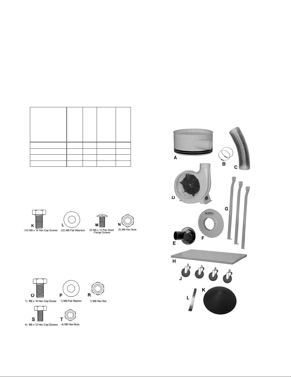
Base Unit
(SN 710701)
Base Unit
(SN 710703)
30M Filter Bag
Kit (SN
708636F)
Canister Filter
Kit (708639B)
DC-1200VX-BK1 x x
DC-1200VX-CK1 x x
DC-1200VX-BK3 x x
DC-1200VX-CK3 x x
Table – DC-1200VX Dust Collector cartons
Hardware Bag for Base Unit (SN DC1100-HP)
16 – M8 x 16 Hex Cap Screws (K)
22 – M8 Flat Washers (L)
08 – M6 x 12 Pan Head Flange Screws (M)
06 – M8 Hex Nuts (N)
Base Units
(SN 71070 1 an d 71 0703)
1 – Housing (A)
2 – Hose Clamps (B)
1 – Hose (C)
1 – Impeller (Motor/Fan Assembly) (D)
1 – Inlet Port (E)
1 – Impeller Cover (F)
3 – Support Legs (G)
1 – Base (H)
4 – Casters (J)
1 – Owner's Manual (not shown)
1 – Warranty Card (not shown)
1 – Hardware Bag Base Assly. (SN DC1100 -HP)
1 – Hardware Bag, Cone Assly. (SN DC1 100-HP2)
Base Assembly Hardware
Hardware Bag for Cone Assembly
1 – M8 x 16 Hex Cap Screw (O)
1 – M8 Flat Washer (P)
1 – M8 Hex Nut (R)
4 – M6 x 12 Hex Cap Screws (S)
4 – M6 Hex Nuts (T)
Cone Assembly Hardware
(SN DC1100-HP2)
Base Machine Shipping Contents
7
Page 8
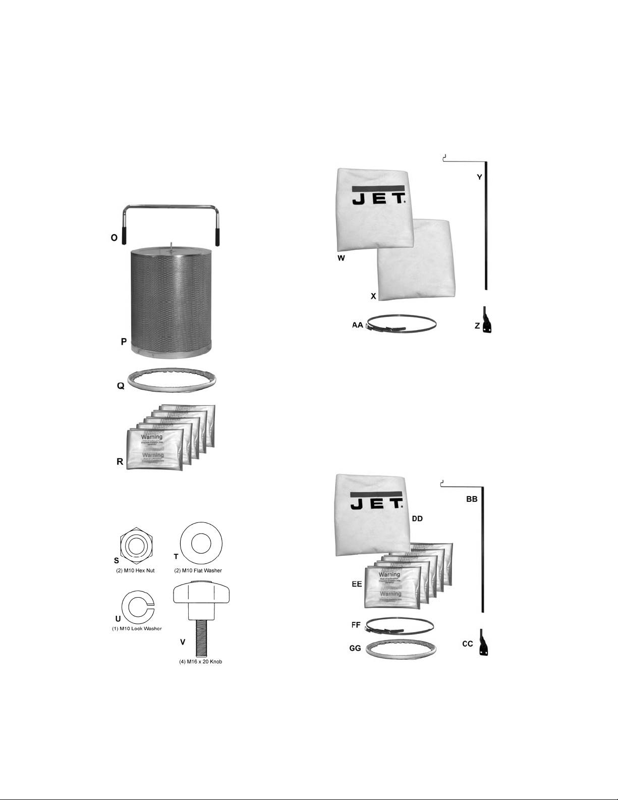
Canister Filter Kit
(SN 708639B)
1 – Handle (O)
1 – Canister Filter (P)
1 – Snap Ring (Q)
5 – Collector Bags (R)
1 – Canister Filter Hardware Bag (SN DC1100-CHP)
Contains:
(2) M10 Hex Nuts (S)
(2) M10 Flat Washers (T)
(1) M10 Lock Washer (U)
(4) Knobs (V)
30 Micron Bag Filter Kit
(SN 708636F)
1 – Upper Bag Hanger (Y)
1 – Hanger Bracket (Z)
1 – Collector Bag (X)
1 – Filter Bag (W)
1 – Retainer St rap (AA)
Canister Filter Kit Contents
Canister Filter Hardware
(SN DC1100-CHP)
30 Micron Bag Filter Kit Contents
5 Micron Bag Filter Kit (Optional)
(SN 708636MF)
1 – Upper Bag Hanger (BB)
1 – Hanger Bracket (CC)
1 – Filter Bag (DD)
5 – Collector Bags (EE)
1 – Retainer Strap (FF)
1 – Snap Ring (GG)
Canister Filter Hardware
5 Micron Bag Filter Kit Contents
8
Page 9

Base Unit Assembly
Base
1. Install four casters to the under side of the base as
pictured in Fig. 2.
Referring to Figure 1:
2. Thread the hex nut (B) onto the caster shaft. T he n
slide the lock washer (A) over the caster shaft.
Thread the caster shaft into the threaded hole on the
underside of the base, turn until snug. Tighten the
nut (B) against the base with a 14mm wrench. This
will give the caster proper clearance.
Motor and Fan Assembly
Referring to Figure 2:
3. Place the base (C) with casters on the ground.
Attach the motor and fan assembly (A) to the base
using four each M8 x 16 hex cap screws, and M8 flat
washers (B). Tighten with a 13mm wrench.
The dust collector must not be
connected to the power source during assembly.
Failure to comply may result in serious injury!
Figure 1
Figure 2
Referring to Figure 3:
4. Attach impeller cover (A) to fan housing (D) using
eight M6 x 12 pan head screws (B). Press the inlet
ports (C) onto the inlet guard until it snaps into place.
To reduce the risk of injury from
moving parts, always keep inlet port covered with the
caps provided, if they are not co nnected to a hose.
Failure to comply may result in serious injury!
Connector Housing
5. Attach three support legs (A, Fig. 4) to the base
using six M8 x 16 hex cap bolts and six M8 flat
washers (B, Fig. 4). Hand-tighten only at this time.
Figure 3
Figure 4
9
Page 10

6. Install the housing (A, F ig. 5) to two support legs (B,
Fig. 5) using four M8 x 16 hex cap bolts, eight M8 flat
washers, and four M8 hex nuts (C, Fig. 5). Be sure
hose opening faces fan housing.
Note: For models DC-1200VX-BK1 or DC1200VX-BK3 only – Bef ore attac hing third support
bracket, place the hanger bracket (D, Fig.5)
between the support brack et and the housing.
7. Tighten all nuts and bolts at this time with a 13mm
wrench.
Cone Assembly
Referring to Figure 6:
8. Mount the cone support bracket (E) to the housing
with four M6x12 hex cap screws (F), and tighten from
beneath with four M6 hex nuts (G).
9. Install the cone (H) from beneath using the M8x16
hex cap screw (J), M8 f lat washer (K), and M8 hex
nut (L), and tighten.
Figure 5
Hose
Referring to Figure 7:
10. Attach the hose (B) between the fan housing (A) and
the impeller housing (D) with two clamps (C).
Tighten the clamps to secure the hose.
This completes the Base Unit assembly. If you purchased
the DC-1200V X-BK1 or DC-1200VX-BK3 Dust Collector
(filter bag version), continue on the followi ng page. If you
purchased the DC-1200VX-CK1 or DC-1200VX-CK3
Dust Collector (canister filter version), proceed to
Canister Kit Assemb ly section on page 12.
Figure 6
Figure 7
10
Page 11

Filter Bag Kit Assembly
If you purchased Model DC-1200VX-B K1 or DC-1200VXBK3 Dust Collector, this section describes the assembly
and installation of the contents of the 30 Micron Filter Bag
Kit (SN 708636F). These instructions also apply to the
optional 5 Micron Filter Bag Kit (SN 708636MF).
Filter Bag Installation
Referring to Figure 8:
1. Place the hanger (A) on the hanger bracket (B).
2. Slide the filter bag loop (C) over the hanger hook.
3. Feed the retai ner strap (D ) through the loop s on the
filter bag (E) and fasten to the collector housing (F).
Figure 8
Collector Bag Installation
Referring to Figure 9:
4. Insert the ring of the collector bag (A ) at an angle into
the housing (B) through the opening at the bottom.
Pull down on the bag to make sure it “seats” in the
housing.
5. Position the plastic window in front so that you can
easily see when the collector bag is full.
After completing the filter bag and collector bag
installation, proceed to Electrical Connections.
Figure 9
11
Page 12

Canister Kit Assembly
If you purchased Model DC-1200VX-CK1 or DC-1200VXCK3 Dust Collector, this section describes the assembly
and installation of the contents of the Canister Kit
(SN 708636F).
Canister Filter
1. Mount the handle onto the canister filter with two
M10 hex nuts, two M10 flat was hers, and a M10 lock
washer (Figure 10).
2. Mount the canister filter on top of the collector
housing (A, Fig. 5) and tighten the knobs on the
canister filter (Figure 10).
Collector Bag
3. Place the ring over the top of the pla stic bag a nd fold
over the bag approximately three inches, Figure 11.
4. Insert the snap ring (A, Fig. 12) of the collector bag
into the bottom of the housing at an angle.
5. Pull down on the ring to make sure it “seat s” in the
housing.
Figure 10
Figure 11
Note: make sure the snap ring “snap s” into pl ace
in the housing, and also that the pl astic bag hangs
down approximately 3” so that there are no air
leaks.
Figure 12
12
Page 13

Electrical Connections
Dust Collector RF Remote
All electrical connections must
be done by a qualified electrician.
All adjustments or repairs must be done with the
dust collector disconnected from the power source,
unplugged. Failure to comply may result in ser ious
injury!
The DC-1200VX single phase dust collectors are rated
for 230V Only. The dust collector is not supplied with a
plug. Use a plug and outlet rated at least 20 amps. The
circuit for the machine should also be protected by at
least a 20 amp circuit breaker or fuse.
The DC-1200VX three phase dust collectors are rated
for 230V/460V, Prewired 230V. If you wish to run these
on 460 volt, refer to the wiring diagram found on the
inside of the switch box cover.
Keep in mind that a circuit being used by other
machines, tools, lights, heaters, etc. at the same time
will add to the electrical load. A dedicated circuit to the
dust collector will give you the best results since dust
collectors are generally used at the same time other
tools are running.
Turning th e Machine On & Off
This machine is intend ed for
indoor use only.
All Models
Before hooking up to the power source, make sure that
the switch is in the off position.
Power Control (optional)
The DC-RC230 Remote Power Control (Figure 14)
should be used for activating Dust Collection units
powered by 230V only up to 3HP, 1 Phase. The DCRC230 Remote Power Control unit is rated at 230V,
Single Phase only. Use an outlet rated at least 20amps.
The circuit for the device being controlled by the DCRC230 should also be protected by at least a 20 amp
circuit breaker or fuse.
Before hooking up to the power source, make sure that
the switch is initially in the off position on both the dust
collector and remote control unit (Figure 13).
Turning the DC-RC230 On & Off
This machine is intend ed for
indoor use only.
1. Plug the dust collector into the main unit
(Figure 14) and plug the main unit into the power
outlet.
To start a machine or device:
1. Turn the machine itself on.
2. On the main unit place the switch to the ON position
(Figure 13A). The red LED on the main unit should
light up.
3. Press the button on the remote control transmitter
(Figure 14) to turn the machine on.
4. To stop the machine, press the button on the
remote control transmitter again.
Turn the dust collector o n by pressing the Start button
mounted next to the motor. Press the Stop button to turn
off the dust collector.
Remote Control (Optional Accessory)
The DC-RC230 RF Remote Power Control unit is
available as an optional accessory (contact Customer
Service by calling the number on the cover).
Important: The DC-RC230 Remote Power Control can
be used for activating Dust Collect ion units powered by
230V only up to 3HP, single phase only.
Figure 13A Figure 13B
Figure 14
When the machine is running, it can be stopped by
placing the switch on the main unit in the off position
(Figure 14). To restart, repeat steps 3 and 4.
13
Page 14

Changing Operating Frequency
If several devices are controlled by the same type
remote control unit, each remote co ntrol unit can be set
to operate at its' own unique operating frequency as
follows:
Referring to Figure 15:
1. Unplug the DC-RC230 Remote Power Control
unit.
5. Remove the back covers of the main unit (A) a nd
remote control switch (B).
6. Locate the DIP switch (C) in each unit.
7. Change the position of the DIP switches in the main
unit (A) to any combination desired as long as they
are not the same as other units that may be present
and located within the radio frequency range.
8. Set the DIP switches (C) in the remote control
switch (B) to match the switch settings in the main
unit (A).
9. Replace the back covers to the main unit and
remote control switch.
10. Operate a device as described in Turning the DC-
RC230 On & Off and verify that other devices using
the same type remote control do not turn on.
Note: Mount ing hard ware i s not inc luded and must be
supplied by the machine’s owner or user.
1. Place RC Power Control Unit (A) on the open
clearing of the base (B) of the dust collector near
the motor (C).
2. Using a marker, mark the base through the
mounting holes of the power control units mounting
tabs.
3. Drill two holes (D) through the base where
marked.
4. Insert screws through the tabs and base. Place
washers and hex nuts on the threaded ends of the
screw underneath the base and tighten.
Figure 15
Installing the DC-RC Remote Power
Control
The DC-RC230 Remote Power Control unit can be
placed anywhere for convenience and portabilit y if used
to control other machines or it can be mounted as a
permanent part of a machine, such as the DC-1200VX
Dust Collector.
To m ount t he DC-RC230 Remote Power Control (refer
to Figure 16):
Figure 16
14
Page 15

Maintenance
Cleaning the Canister Filter – DC-1200VXCK1 and DC-1200VX-CK3
Never perform maintenance on this
machine before turning switch off and removing
plug from power source. Failure to comply may
cause serious injury!
Cleaning the Filter Bag - DC-1200VX-BK1
and DC-1200VX-BK3
Wearing a particle mask or
respirator for protection against fine dust particles
during cleaning is highly recommended.
During first use and after cleaning, the filter bag may
allow some dust to escape. This is normal and will stop
after a short period of time.
Clean both the filter and collector bags frequently to
keep the collector's performance at its optimum. To
clean:
1. Disconnect the m ac hine from the power source.
2. Unhook the filter bag from the hanger and shake
the bag so that the majori ty of the dust falls into
the collect or bag.
3. Loosen the retaining strap, and remove the filter
bag from the housing.
4. Turn the bag inside out and cl ean.
5. Turn the bag outsi de in and r e- att ac h to t he
housing using the r etainer strap to secure.
Removing the Collector Bag –
DC-1200VX-BK1 and DC-1200VX-BK3
1. Disconnect the m ac hine from the power source.
2. Remove the coll ector bag by pushi ng the ring of
the collect or bag upwards and pulling the bag
out at an angle.
3. Empty the contents into an appropriate
container.
4. Turn the bag inside out and cl ean.
5. Turn the bag outsi de in and insert into the
housing.
To replace the collector bag, refer to Collector Bag
Installation on page 11.
Use the proper type hose to connect the dust collector
to the machine being operated. Dryer vent hose is not
acceptable for this purpose. Contact your nearest JET
distributor for the full line of JET Dust Collector Hoses
and Accessories. Customize your installation and
obtain maximum performance with JET's dust hoods,
hoses, clamps, fittings, and blast gates.
Never perform maintenance on this
machine before turning switch off and removing
plug from power source. Failure to comply may
cause serious injury!
Clean both the filter and collector bags frequently to
keep the collector's performance at its optimum.
To clean the filter, turn the handle a couple of rotations
so the dust falls into the collector bag.
Removing the Collector Bag –
DC-1200VX-CK1 and DC-1200VX-CK3
Wearing a particle mask or
respirator for protection against fine dust particles
during cleaning is highly recommended.
1. Disconnect the m ac hine from the power source
outlet.
2. Remove the coll ector bag by pushi ng the ring of
the collector bag upwards at an angle and
pulling the bag and snap ring out.
3. Empty the contents into an appropriate
container.
To replace the collector bag, refer to the Collector Bag
section on page 12.
Motor
Make frequent inspections of the motor fan and blow out
(with low pressure air hose) or vacuum any
accumulation of foreign material in order to maintain
normal motor ventilation.
Connecting the Dust Collector to a
Machine
Use the proper type hose to connect the dust collector
to the machine being operated. Dryer vent hose is not
acceptable for this purpose. Contact your nearest JET
distributor for the full line of JET Dust Collector Hoses
and Accessories. Customize your installation and
obtain maximum performance with JET's dust hoods,
hoses, clamps, fittings, and blast gates.
Grounding the Dust Collection System
The dust collection system includes the dust collector
and the hose, or ductwork you use to connect the tools.
The dust collector is grounded through the ground wire
in the cord. The hose or ductwork you use to connect
the tool to the dust collector must also be grounded.
15
Page 16

Parts Breakdown for the DC-1200VX Dust Collector
16
Page 17

Ordering Replacement Parts
To order parts or reach our service department, call 800-274-6848, Monday through Friday (see our website f or busi ness
hours, www.jettools.com). Having the Model Number and Serial Number of your machine available when you call will
allow us to serve you quickly and accurately.
Parts List for the DC-1200VX Dust Collector
Index No. Part No. Description Size Qty
1 ................ 411035W ................... Impeller Housing ...................................................... ...................................... 1
2 ................ 411026W ................... Motor Bracket........................................................... ...................................... 1
3 ................ 998621 ...................... Strain Relief ............................................................. ...................................... 1
.................. 709421 ...................... Strain Relief ............................................................. M20 (for 3PH type) ........ 1
4 ................ MA411003 ................. Motor ........................................................................ 2 HP, 1PH ..................... 1
.................. MA411003-3 .............. Motor ........................................................................ 2 HP, 3 PH .................... 1
.................. DC1100-50W............. Motor Fan Cover (not shown) .................................. ...................................... 1
.................. MF411012 ................. Motor Fan (not shown) ............................................. ...................................... 1
.................. CA003030 ................. Runn ing Capacitor (not shown) ............................... 30MFD, 300V ................ 1
.................. CA020010 ................. Startin g Capacitor (not shown) ................................ 200MFD, 125V .............. 1
5 ................ 411051 ...................... Switch Box ............................................................... ...................................... 1
6 ................ 411053 ...................... Switch Plate ............................................................. ...................................... 1
.................. 411057 ...................... Switch Plate ............................................................. for 3PH Switch .............. 1
7 ................ 994542 ...................... Switch ...................................................................... 1 PH 230 V ..................... 1
.................. 994507 ...................... Switch ...................................................................... 3 PH, 230/460V ............. 1
8 ................ IC420002 ................... Power Cord………………………………..14A WG x 3C 300V (for 1PH) .......... 1
.................. IC411008 ................... Power Cord………………………………..14AWG x 4C 600V (for 3PH) .......... 1
9 ................ 420051 ...................... Motor Packing .......................................................... ...................................... 1
10 .............. AB411059.................. I mpeller .................................................................... 12” ................................. 1
11 .............. 411036W ................... Inlet Guard ............................................................... ...................................... 1
12 .............. PM1300-112 .............. Inlet Port................................................................... 2 @ 4” ........................... 1
13 .............. 420203 ...................... Inlet Cap................................................................... ...................................... 2
14 .............. 430034 ...................... Inlet Flange Packing ................................................ ...................................... 1
15 .............. 411041W ................... Base ......................................................................... ...................................... 1
16 .............. 402036 ...................... Piv oting Caster......................................................... ...................................... 4
17 .............. 420012W ................... Housing .................................................................... ...................................... 1
18 .............. 402004W ................... Support .................................................................... ...................................... 3
20 .............. 411009 ...................... Hose......................................................................... 5”x65(CM) ..................... 1
21 .............. 420010 ...................... Rin g Clamp .............................................................. 5” ................................... 2
31 .............. ST039304 .................. Tapping Screw ......................................................... M3.5x12(AB) ................. 6
32 .............. KS050525.................. Key ........................................................................... 5x5x25 .......................... 1
34 .............. TS-1540061............... Nu t ........................................................................... M8 ............................... 10
35 .............. TS-0561031............... Nu t ........................................................................... 3/8
36 .............. SH080402 ................. Hex Head Bolt .......................................................... M8x20 L.H ..................... 1
37 .............. TS-1490011............... Hex Head Bolt .......................................................... M8x12 ........................... 4
38 .............. TS-1490021............... Hex Head Bolt .......................................................... M8x16 ......................... 16
39 .............. TS-1490041............... Hex Head Bolt .......................................................... M8x25 ........................... 4
40 .............. TS-1554041............... Pan Head Bolt W/Flange ......................................... M6x 12 ........................... 2
41 .............. TS-0680031............... Flat Washer.............................................................. M8 ................................. 1
42 .............. TS-1554041............... Pan Head Bolt W/Flange ......................................... M6x 12 ........................... 8
43 .............. TS-0680031............... Flat Washer.............................................................. M8 ............................... 34
44 .............. TS-0720081............... Sprin g Washer ......................................................... M8 ................................. 8
45 .............. TS-1551071............... Sprin g Washer ......................................................... M10 ............................... 4
46 .............. ST059304 .................. Tapping Screw ......................................................... M5x12 ........................... 2
.................. SP040500.................. Pan Head Screw ...................................................... M4x25 (for 3PH type) .... 2
47 .............. DC1100-47 ................ Cone ........................................................................ ...................................... 1
48 .............. DC1100-47-1 ............. Support Bracket ....................................................... ...................................... 1
49 .............. TS-1490021............... Hex Cap Screw ....................................................... M8x16 ........................... 1
50 .............. TS-1550061............... Flat Washer.............................................................. M8 ................................. 1
51 .............. TS-1540061............... Hex Nut .................................................................... M8 ................................. 1
52 .............. TS-1482021............... Hex Head Bolt ......................................................... M6x12 ........................... 4
53 .............. TS-2311061............... Hex Nut .................................................................... M6 ................................. 4
”-16UNC ................... 4
17
Page 18

Index No. Part No. Description Size Qty
54 .............. PM1300-151 .............. Inlet Guard ............................................................... ...................................... 2
55 .............. DCRC-111 ................. Tapping Screw ......................................................... M3.5x10(AB) ................. 4
.................. DC1200A-NP............. Name Plate (not shown) .......................................... ................ ...................... 1
.................. DC1100-HP ............... Hardware Package (not shown)............................... ...................................... 1
.................. DC1100-HP2 ............. Hardware Package for Cone Assembly (index # 49 thru 53) .......................... 1
.................. DC1200A-CS............. Centrifugal Switch (not shown) ................................ ...................................... 1
.................. DC1900-53 ................ Warning Label (not shown) ...................................... ...................................... 1
.................. DC1200-53 ................ Grounding Label (not shown)................................... ...................................... 1
.................. DC1200-54 ................ Di rection Label (not shown) ..................................... ...................................... 1
.................. STRIPE-1-3/4 ............ JET Stripe (not shown) ............................................ 1-3/4” ....................... per ft
.................. DC1100VX-56 ........... Vortex Cone Decal (not shown)………….88.9x28.58mm (3-1/2”x1-1/8”) ....... 1
.................. DC1100VX-57 ........... Vortex Cone Decal (not shown)………….228.6 x 73mm (9”x2-7/8”) .............. 1
18
Page 19

Canister Filter Kit (708639B)
Index No. Part No. Description Size Qty
.................. 708639B .................... Canister Filter Kit (index #1-24) ............................... ........................................
1 ................ 331050 ...................... Handle...................................................................... ...................................... 1
2 ................ TS-1540071............... Hex Nut .................................................................... M10 ............................... 2
3 ................ TS-1550071............... Flat Washer.............................................................. M10 ............................... 2
4 ................ TS-2361101............... Lock Washer ............................................................ M10 ............................... 1
5 ................ BR000052 ................. Rivet ......................................................................... 5-2 ................................. 3
6 ................ 331014 ...................... Bracket ..................................................................... ...................................... 1
7 ................ 150623 ...................... Pad........................................................................... ...................................... 1
8 ................ 331051 ...................... Soft Grip Handle ...................................................... ...................................... 2
9 ................ TS-1540041............... Hex Nut .................................................................... M6 ................................. 8
10 .............. 708739 ...................... Filter ......................................................................... ...................................... 1
11 .............. 331052 ...................... Shaft......................................................................... ...................................... 1
12 .............. TS-1482041............... Hex Cap Screw ........................................................ M6X20 ........................... 4
13 .............. TS-2361061............... Lock Washer ............................................................ M6 ................................. 4
14 .............. TS-1550041............... Flat Washer.............................................................. M6 ................................. 4
15 .............. 331012 ...................... Scraper .................................................................... ...................................... 2
16 .............. 331017 ...................... Strip.......................................................................... ...................................... 2
17 .............. 331015 ...................... Press Plate............................................................... ...................................... 2
18 .............. TS-1482021............... Hex Cap Screw ........................................................ M6x12 ........................... 4
19 .............. 331037 ...................... Knob......................................................................... ...................................... 4
20 .............. 331031 ...................... Pad........................................................................... ...................................... 1
21 .............. 331009 ...................... Support .................................................................... ...................................... 1
22 .............. ST049200 .................. Tapping Screw ......................................................... M4X8 ............................. 4
23 .............. 331038 ...................... Snap Ring ................................................................ ...................................... 1
24 .............. 709563 ...................... Plas tic Bag ............................................................... ...................................... 5
..................DC1100-CHP...........Canister Hardware Package....................................................................................
19
Page 20

30 Micron Filter Bag Kit (708636F)
Index No. Part No. Description Size Qty
.................. 708636F .................... 30 Micron Filter Bag Kit (index #1-5) ....................... ........................................
1 ................ 708698 ...................... Filter Bag.................................................................. 30 Micron Bag ............... 1
2 ................ AB410012.................. Retain er Strap .......................................................... ...................................... 1
3 ................ 708699A .................... Collection Bag ......................................................... ...................................... 1
4 ................ 430038 ...................... Han ger ..................................................................... 30 Micron Bag Hanger .. 1
5 ................ 523011W ................... Hanger Bracket ........................................................ ...................................... 1
20
Page 21

5-Micron Filter Bag Kit (708636MF) Optional Accessory
Index No. Part No. Description Size Qty
.................. 708636MF ................. 5-Micron Filter and Collection Bag Kit (index # 1-6)
1 ................ 708706 ...................... Filter Bag ................................................................. 5 Micron ........................ 1
2 ................ AB410012.................. Retain er Strap .......................................................... ...................................... 1
3 ................ 331038 ...................... Snap Ring ................................................................ ...................................... 1
4 ................ 709563 ...................... Plas tic Bag (Package of 5)....................................... ...................................... 1
5 ................ 430038 ...................... Han ger .................................................................... ...................................... 1
6 ................ 523011W ................... Hanger Bracket ........................................................ ...................................... 1
21
Page 22

Electrical Connections
Wiring Diagram For 3 Phase 230/460V Dust Collector (DC-1200VX)
Wiring Diagram For Single Phase 230V Only Dust Collector (DC-1200VX)
22
Page 23

23
Page 24

427 New Sanford Road
LaVergne, Tennessee 37086
Phone: 800-274-6848
www.jettools.com
24
 Loading...