

Page 1
This .pdf document is bookmarked
Operating Instructions and Parts Manual
14-inch Deluxe Pro Band Saw
Models: JWBS-14DXPRO
(Shown with optional Rip Fence)
JET
427 New Sanford Road
LaVergne, Tennessee 37086 Part No. M-710116
Ph.: 800-274-6848 Revision C1 10/2014
www.jettools.com Copyright © 2014 JET
Page 2

Warranty and Service
JET warrants every product it sells against manufacturers’ defects. If one of our tools needs service or repair, please contact
Technical Service by calling 1-800-274-6846, 8AM to 5PM CST, Monday through Friday.
Warranty Period
The general warranty lasts for the time period specified in the literature included with your product or on the official JET
branded website.
• JET products carry a limited warranty which varies in duration based upon the product. (See chart below)
• Accessories carry a limited warranty of one year from the date of receipt.
• Consumable items are defined as expendable parts or accessories expected to become inoperable within a
reasonable amount of use and are covered by a 90 day limited warranty against manufacturer’s defects.
Who is Covered
This warranty covers only the initial purchaser of the product from the date of delivery.
What is Co vered
This warranty covers any defects in workmanship or materials subject to the limitations stated below. This warranty does not
cover failures due directly or indirectly to misuse, abuse, negligence or accidents, normal wear-and-tear, improper repair,
alterations or lack of maintenance. JET woodworking machinery is designed to be used with Wood. Use of these machines in
the processing of metal, plastics, or other materials may void the warranty. The exceptions are acrylics and other natural items
that are made specifically for wood turning.
Warranty Limitations
Woodworking products with a Five Year Warranty that are used for commercial or industrial purposes default to a Two Year
Warranty. Please contact Technical Service at 1-800-274-6846 for further clarification.
How to Get Technical Support
Please contact Technical Service by calling 1-800-274-6846. Please note that you will be asked to provide pr o of of ini tial
purchase when calling. If a product requir es further inspection, the Technical Service repr esent a tive will explain and assis t
with any additional action needed. JET has Authorized Service Centers located throughout the United States. For the name of
an Authorized Service Center in your area call 1-800-274-6846 or use the Service Center Locator on the JET website.
More Information
JET is constantly adding new products. For complete, up-to-date product information, check with your local distributor or visit
the JET w ebsite.
How S tate Law Applies
This warranty gives you specific legal rights, subject to applicable state law.
Limitations on This Warranty
JET LIMITS ALL IMPLIED WARRANTIES TO THE PERIOD OF THE LIMITED WARRANTY FOR EACH PRODUCT.
EXCEPT AS STATED HEREIN, ANY IMPLIED WARRANTIES OF MERCHANTABILITY AND FITNESS FOR A PARTICULAR
PURPOSE ARE EXCLUDED. SOME STATES DO NOT ALLOW LIMITATIONS ON HOW LONG AN IMPLIED WARRANTY
LASTS, SO THE ABOVE LIMITATION MAY NOT APPLY TO YOU.
JET SHALL IN NO EVENT BE LIABLE FOR DEATH, INJURIES TO PERSONS OR PROPERTY, OR FOR INCIDENTAL,
CONTINGENT, SPECIAL, OR CONSEQUENTIAL DAMAGES ARISING FROM THE USE OF OUR PRODUCTS. SOME
STATES DO NOT ALLOW THE EXCLUSION OR LIMITATION OF INCIDENTAL OR CONSEQUENTIAL DAMAGES, SO THE
ABOVE LIMITATION OR EXCLUSION MAY NOT APPLY TO YOU.
JET sells through distributors only. The specifications listed in JET printed materials and on official JET website are given as
general information and are not binding. JET reserves the right to effect at any time, without prior notice, those alterations to
parts, fittings, and accessory equipment which they may deem necessary for any reason whatsoever. JET
are not sold in Canada by JPW Industries, Inc.
Product Listing with Warranty Period
90 Days – Parts; Consumable items; Light-Duty Air Tools
1 Year – Motors; Machine Accessories; Heavy-Duty Air Tools; Pro-Duty Air Tools
2 Year – Metalworking Machinery; Electric Hoists, Electric Hoist Accessories; Woodworking Machinery used
for industrial or commercial purposes
5 Year – Woodworking Machinery
Limited Lifetime – JET Parallel clamps; VOLT Series Electric Hoists; Manual Hoists; Manual Hoist
Accessories; Shop Tools; Warehouse & Dock products; Hand Tools
NOTE: JET is a division of JPW Industries, Inc. References in this document to JET also apply to JPW Industries, Inc., or any
of its successors in interest to the JET brand .
®
branded products
2
Page 3

Table of Contents
Warranty and Servic e .......................................................................................................................................... 2
Table of Contents ................................................................................................................................................ 3
Shipping Contents ............................................................................................................................................... 7
Contents of Shipping Containers ...................................................................................................................... 7
Container Two .................................................................................................................................................. 7
Tools Required for Assembly ............................................................................................................................ 7
Fasteners for JWB S - 14DXPRO ........................................................................................................................ 7
Assembly ............................................................................................................................................................. 8
Unpacking and Cleanup ................................................................................................................................... 8
Stand ............................................................................................................................................................... 8
Mounting the Tr unnion Bracket to the Band Saw .............................................................................................. 8
Mounting the Table to the Bandsaw .................................................................................................................. 9
Grounding Inst r uc tions ....................................................................................................................................... 10
115 Volt Operati on ......................................................................................................................................... 10
230 Volt Conversion ....................................................................................................................................... 10
Extensi on Cords ............................................................................................................................................. 11
Adjustments ....................................................................................................................................................... 12
Tilting the Table .............................................................................................................................................. 12
Adjusting 90° Table Stop ................................................................................................................................ 12
Changing Blades ............................................................................................................................................ 13
Adjusting Bl ade Tension ................................................................................................................................. 14
Adjusting Bl ade Trac ki ng ................................................................................................................................ 15
Adjusting Upper Blade Guide Assembly.......................................................................................................... 15
Adjusting Upper Bl ade Guides and Thrust Bearings........................................................................................ 16
Adjusting Lower Blade Guides and Thrust Beari ngs........................................................................................ 16
Adjusting Guide Post Parallel To Blade .......................................................................................................... 17
Changing Blade Speeds ................................................................................................................................. 17
Optional Accessories ......................................................................................................................................... 1 8
Troubleshooting ................................................................................................................................................. 18
Parts .................................................................................................................................................................. 18
Body Assembly (JWBS-14DXPRO) ................................................................................................................ 19
Body Assembly (JWBS-14DXPRO) ................................................................................................................ 20
Closed Stand Assembly (JWBS-14DXPRO) ................................................................................................... 24
Closed Stand Assembl y ( JWBS14-DXPRO ) ................................................................................................... 2 5
Electri c al Schematic – 115V ........................................................................................................................... 26
Electri c al Schematic – 230V ........................................................................................................................... 27
3
Page 4

0. Read and understand the ent ire owner’s manual befor e att em pting assembly or operation.
1. Read and understand the warning s posted on the m achine and in t his manual. Failure to com ply with all of
these warnings may c ause serious i njury.
2. Replace the warning labels if they become obscured or removed.
3. This band saw is de signed and intended f or use by properl y trained and experi enced personnel only . If you
are not familiar with the proper and safe operation of a band saw, do not use until proper training and
knowledge have been obtained.
4. Do not use this band saw for other t han i ts intended use. If used for other purposes, JET disclaims any real or
implied warrant y and holds itself harmless from any injury t hat m ay result from that use.
5. Always wear approved safety glasses/face shields while using this ban d saw. Every day ey eglasses only have
impact resistant lenses; they are not safety gl asses.
6. Before operating this band saw, remove ti e, rings, watches and other j ewelry, and roll sleev es up past the
elbows. Remove all loose clothing and confine long hair. Non-slip footwear or anti-skid floor strips are
recommended. Do not wear gloves.
7. Always use the blade guard on al l ''thr ough-sawing'' operat ions. A through-sa wing operation i s one in which
the blade cuts com pletely through the workpiece.
8. Some dust created by power sanding, sawing, grinding, drilling and other construction activities contain
chemicals known to cause cancer, birth defects or other reproductive harm. Some examples of these
chemicals are:
• Lead from lead based paint.
• Crystalli ne sil ic a from bricks, cement and other m asonry pr oduc ts.
• Arsenic and chromium from chemically treated lumber .
Your risk of ex posure varies, depending on how of ten you do this type of work. To reduce your exposure to
these chemical s, work in a well-ventil ated area and work with approved safety equipment, such as face or
dust masks that are specifically designed to fil ter out microscopic partic les.
9. Do not operate this machine while tired or under the influence of dr ugs, alcohol or any medicati on.
10. M ak e c er tain the switch is in the OFF position before connecti ng the machine to the power supply.
11. M ak e c er tain the machine is properly grounded.
12. M ak e all machine adjustments or maintenance with the machine unplugged f rom the power source.
13. Rem ove adjusti ng keys and wrenches. F orm a habi t of checki ng to see that keys and adjusti ng wrenche s are
removed from the machine before turning it on.
14. K eep safety guards in pl ace at all tim es when the machine i s in use. If removed f or maintenance purposes,
use extreme caution and replace the guards immedi ately.
15. M ak e sure t he band sa w is firmly secured to the fl oor or bench before use.
16. Check dam aged parts. Before further use of t he machine, a guard or other part that is damaged should be
carefully checked to determine that it will operate properly and perform its intended function. Check for
alignment of m ov ing par ts, binding of moving parts, breakage of par ts, mounting and any other c onditions that
may affect it s operati on. A guard or other part that is damaged shoul d be pr oper ly repaired or replaced.
17. P r ov ide for adequate space surroundi ng work area and non-glare, ov er head lighting.
18. K eep the floor around the machi ne cl ean and free of scrap material, oil and grease.
4
Page 5

19. K eep v isitors a safe distance from the work area. Keep children away.
20. M ak e y our workshop chi ld proof with padlocks, master switches or by removing starter keys.
21. Give your work undivided attent ion. Looking around, c arrying on a c onversation and “horse-play” are c ar eless
acts that can resul t in seri ous i njury.
22. Mai ntain a balanced stance at all tim es so that you do not fall into the blade or other m oving parts. Do not
overreach or use exc essive force to perform any machine operation.
23. Use the ri ght t ool at the corr ect speed and f eed rate. Do not for ce a tool or attac hment to do a job f or which it
was not designed. The right tool will do the job better and safer.
24. Use recom mended accessories; improper accessories may be hazardous.
25. Maintain tools with care. Keep saw blades sharp and clean for the best and safest performance. Follow
instructions for lubricating and changing accessories.
26. M ak e sure t he work piece is held firmly agai nst the rip fence or miter gauge as it is fed through the blade.
27. Turn off the machine befor e cl eaning. Use a brush or compressed air to rem ov e c hips or debris — do not use
your hands.
28. Do not stand on the machine. Seri ous i njur y c ould oc cur if the machine tips over.
29. Nev er leave t he machine running unat t ended. Turn t he power off and do not l eave the machine unti l it c omes
to a complete stop.
30. Remove loose items and unnecessary work pieces from the area bef ore starting the machine.
Familiariz e y our self with the following safety notices used in this manual:
This means that if precautions are not heeded, it may result in minor injury and/or possible
machine damage.
This means that if precautions are not heeded, it m ay result in serious injur y or possibly even
death.
5
Page 6

Specifications
Stock Number .......................................................................................................................................... 710116K
Model Number .............................................................................................................................. JWBS-14DXPro
Cutting Capacity (height) ................................................................................................................................... 12 ”
Cutting Capacity (width) .............................................................................................................................. 13-1/2”
Minimum Blade Width ...................................................................................................................................... 1/8”
Maximum Blade Width ..................................................................................................................................... 3/4 ”
Blade Length .................................................................................................................................................. 105”
Blade Speed ............................................................................................................................. 1500 / 3000 SFPM
Table Size ................................................................................................................................................ 15” x 15”
Table Slot Size ................................................................................................................................. 3/8”D x 3/4”W
Table He ight from Floor ....................................................................................................... ....................... 4 3-1/2 ”
Table Tilt (L-R) ....................................................................................................................................... 45°R / 10°
Dust Chute Diameter .................................................................................................................................. 4” O.D.
Overall Dim ensi ons (wit hout fence) .......................................................................................... 77”H x 28”W x 29”D
Footprint Dimensions .......................................................................................................................... 17”W x 24”D
Motor ...................................................................................................... 1.25 HP, 1Ph, 115/230V (prewi r ed 115V )
Net Weight (approx.) .................................................................................................................................... 247 lb.
Shipping Weight (approx.) ............................................................................................................................ 258 lb.
The specifications in this m anual are given as general information and are not bi nding. JET reserves the right t o
effect, at any time and without prior notice, alterations to parts, fittings, and accessory equipment deemed
necessary for any reason whatsoever.
6
Page 7
Shipping Contents
Open both shippi ng containers and chec k for shipping
damage. Report any damage immediately to your
distributor and shipping agent. Read the instruction
manual thoroughly for assembly, maintenance and
safety instructions.
Contents of Shipping Containers
Container One
1 Stand
1 Door
2 Stand Supports
1 Accessory Package
Containe r Two
1 Saw body w/ motor
1 Poly-V Belt
1 Trunnion support br ac k et
1 Table
2 Table lock knobs
1 Table pin
1 Table insert
1 Fastener package (see fastener page)
1 Instruction manual
1 Warranty card
Tools Required for Assembly
(2) 10mm and (2)13mm open end wrenches or
adjustable wrenche s
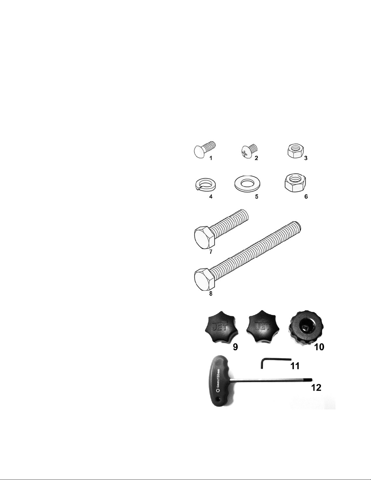
Fasteners for JWBS-14DXPRO
1 – M6x16 carriage bolt (4)
2 – M6x8 pan head screw (1)
3 – M6 hex nut (4)
4 – M8 lock washer (6)
5 – M8 flat washer (8)
6 – M8 hex nut(5)
7 – M8x40 hex cap screw (6)
8 – M8x80 hex cap screw (1)
9 – Lock Knob (2)
10 – Knob (1)
11 – 4mm hex wrench(1)
12 – 6mm T-handle hex wrench ( 1)
7
Page 8
Assembly
Read and understand all
assembly instr uctions before attempting assembly!
Failure to comply m ay cause serious injury!
Unpacking and Clea n up
1. Finish rem oving all cont ents from the shippi ng
carton. Do not discard the carton or packing
material unti l the band saw is assembled and
is running sati sfac torily.
2. Inspect the contents for shipping damage.
Report damage, if any, to your distributor.
3. Compare the contents of the shipping carton
with the contents list in this manual. Report
shortages, if any, to your distributor.
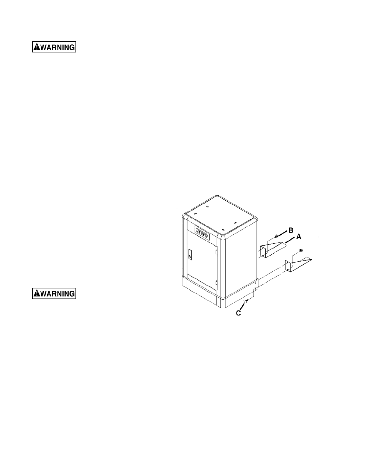
Stand
Attach stand supports to bac k of cabinet BEFORE
placing saw body on top of c abinet.
1. Using four M 6x 16 c ar r iage bolts (C, Fig. 1) and
four M6 nuts (B, Fig. 1) attach the stand
supports (A, Fig. 1) through the saw cabinet.
The bolt must be attached from the inside
bottom of t he saw cabinet (fi g 1). To do t his it
is easiest if you tilt the saw cabinet on it s front
and then install the hardware.
2. Place cabi net stand upright on a level surface.
If the surf ace is uneven then you should l evel
the stand supports by l oosening the nut (B, Fi g
1) and moving the support up or down to
prevent the stand from rocking, then tighten
the nuts.
Saw body is heav y! Use caution
when lifting and stabilize until fi rmly attached t o the
stand! Failur e to com ply may c ause serious i njury!
3. With the aid of a second person, lift the saw
body out of the shipping container and place
onto stand top. Be sure f ront of sa w (wit h JET
logo) faces stand front (Door Side).
4. Li ne up holes i n saw body with holes in t he top
of the stand. Fasten saw body to the stand
with four M8 x 40 hex cap screws, eight M8
washers, four M8 lock washers, and four M8
hex nuts.
Figure 1
Mounting the Trunnion Bracket to
8
Page 9
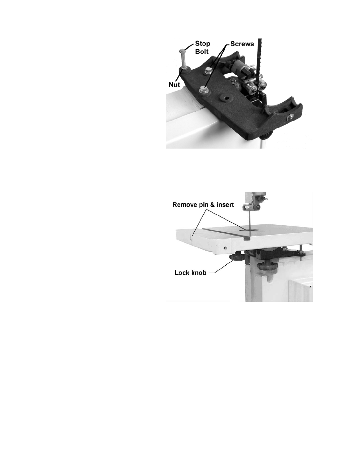
the Band Saw
1. Attach trunnion support to saw body with two
M8 x 40 hex cap screws and two M8 lock
washers. See Figure 2.
2. Thread nut on to table stop bolt (Fig. 2) and
attach to trunnion support bracket as shown.
Once table i s mounted to the t runnion brack et ( see
section below) and the blade is mounted in the
saw (see section “Changing Blades”) you may
choose to f ine tune the blade paral lel to the m iter
slot. Using a square positioned i n the miter slot,
loosen screws shown in F igure 2 and lightly tap the
table into posi tion so the blade is paral lel with the
miter slot. Then gently tighten down the screws.
This adjustment will ensure square cuts when
using a miter gauge. This adjustment will NOT
correct drift of a blade when ripping with a rip
fence.
Figure 2
Mounting the Table to the Bandsaw
1. To mount the table, remove pin and insert from
the table (Fig. 3).
2. Rotate the table so that the saw blade will slide
through the slot in the table. Then orient the
table so the screws will slide into the holes on
the trunnion support bracket. Attach lock knobs
to these screws (Fig. 3)
3. Replace pin and insert .
Figure 3
9
Page 10

Grounding Instructions
This Band Saw must be grounded
while in use to protect the operator from electric
shock.
In the event of a malfunction or breakdown,
grounding provides a path of least resistance for
electric current to reduce the risk of electric shock.
This tool is equipped with an elec tric cor d having an
equipment-grounding conductor and a grounding
plug that look s simil ar to the plug in Figure 20. The
plug must be insert ed into a matching outlet that is
properly i nstalled and groun ded in accordance wit h
all local codes and ordinanc es.
21, if a properly grounded outlet is not available. The
temporary adapter should only be used until a
properly grounded outlet can be installed by a
qualified el ectr ici an. Thi s adapter i s not appli c able i n
Canada. The green colored rigid ear, lug, or tab,
extending fr om the adapter , must be connect ed to a
permanent ground such as a properly grounded
outlet box, as shown in Fi gur e 21.
Do not modify the plug provi ded. If it will not fit t he
outlet, hav e the proper out let i nstall ed by a qualif i ed
electrician.
Improper connection of the equipment-grounding
conductor can re sult i n a risk of elec tric shock. T he
conductor, with insulation having an outer surface
that is green with or without yellow stripes, is the
equipment-grounding conductor. If repair or
replacement of t he elec tric cord or plug is necessary,
do not connect the equipment-grounding conductor
to a live terminal.
Figure 20
Check with a qualified electrician or service
personnel if the grounding instructions are not
completely understood, or if i n doubt as to whether
the tool is properly gr ounded.
Figure 21
230 Volt Conversion
If 230V, single-phase operation is desired, the
following inst r uc tions must be followed:
Disconnect machine from power source.
This band saw is supplied wit h four motor leads that
are connected for 115V operation, as shown in
Figure 22. Reconnect these four motor leads for
230V operation, as shown in Figure 22.
Repair or replace a damaged or worn cord
immediately.
115 V olt Operation
As received fr om the factory, your bandsaw is ready
to run at 115-volt operation. This bandsaw, when
wired for 115 volts, i s intended for use on a circuit
that has an outlet and a plug that looks like the one
illustrated in Figure 20. A temporary adapt er, like the
adapter in Figure 21, may be used to connect this
plug to a two-pole receptacle, as shown in Figure
10
Figure 22
Page 11

The 115V attachment plug supplied with the band
e
saw must be replaced with a UL/CSA listed plug
suitable f or 230V operation, as shown in Fi gure 23.
Contact your l ocal authorized JET servic e center or
qualified electrician for proper procedures to install
the plug. The band saw must comply with all local
and national codes after the 230-volt plug is
installed.
The band saw with a 230-volt plug should only be
connected to an outlet having the same
configurati on (Figure 23). No adapt er is av ailable or
should be used with the 230-volt plug.
Figure 23
Important: In all cases (115 or 230 volts), make
certain the receptacle in question is properly
grounded. If you are not sure, have a registered
electrici an c hec k the rec eptacle.
Extens ion Cords
Use only three wire ext ension cords that have threeprong grounding plugs and three-pole receptacles
that accept the tool’s plug.
Make sure the cor d is in goo d condition, and heavy
enough to carry t he current your band saw will draw.
An undersized c ord will cause a drop in line voltage,
resulting i n loss of power and ov erheating. Table 1
shows the correct size to use depending on cord
length and the ampere rating on your machine’s
nameplate. If in doubt, use the next heavier gauge.
The smaller the gauge num ber , the heavier the cord.
Repair or replace a damaged or worn cord
immediately.
Power Extension Cord
Currant
(Amps)
0-6 120
6-10 120
10-12 120
12-16 120
Line
voltage
Cord length in
feet
0 to 25 18
25 to 50 16
50 to 100 16
over 100 14
0 to 25 18
25 to 50 16
50 to 100 14
over 100 12
0 to 25 16
25 to 50 16
50 to 100 14
over 100 12
0 to 25 14
25 to 50 12
over 50
Cord gaug
not recommended
(AWG)
Table 1
11
Page 12

Adjustments
Tilting the Table
Unplug the machine from the power
source before maki ng any r epair or adjustment!
Failure to comply m ay cause serious injury!
1. Loosen two lock knobs (Fig. 4).
2. Til t table up to 45 degrees to the right or down 10
degrees to the l eft, using the scale mounted t o the
trunnion.
3. Tighten two lock knobs (Fig.4).
Note: Tabl e stop can be rem ov ed or f urther adj usted t o
tilt table to the left.
Adjusting 90° Table Stop
Disconnect machine from the power
source.
Figure 4
1. Loosen l ock knobs (Fig. 4) and tilt table l eft until it
rests against table stop.
2. Tighten Lock knobs
3. Use a square placed on t he table and against the
blade (Fig. 5) t o see if the t able is 90 degrees to the
blade.
4. If an adjustm ent is necessary, loosen lock knob s,
tilt table t o the right, and lock in place.
5. Loosen jam nut and turn table stop (Fig. 4) left or
right to rai se or lower the stop. Tight en jam nut to
hold table stop i n plac e.
6. Unlock table, tilt back onto table rest and confirm
table is 90 degrees with the blade.
7. If necessary, adj ust scale pointer to zero.
Figure 5
Page 13

Changing Blades
Blade teeth are sharp! Use care
when handling the saw blade.
Failure to comply m ay cause serious injury!
1. Disconnect machine from power source.
2. Loosen bl ade tensi on by pushing up on t he rel ease
lever (Fig. 6).
3. Remove the table insert and the table pin.
4. Open both wheel covers.
5. Back off the Thrust Bearing and both the upper and
lower guide beari ngs fr om the blade.
6. Remove t he blade from between upper and l ower
blade guides. Remov e blade from upper and lower
wheels. Turn blade t o dir ect through sl ot in table.
7. Before mounting blade mak e sure the orientation of
the blade is so the teeth are pointing down. If
holding blade in fr ont of you, as if mounted i n the
saw, the teeth should point down on right side of
the loop. If not the blade i s inside out. Twist the
blade right side in to correct this, wear heavy
gloves when doing so.
8. Gui de new blade t hrough t able sl ot. Place bl ade in
upper and lower blade gui des.
9. Place blade i n the middle of the upper and lower
wheel.
10. Replace table insert and table pin.
Tension and track blade bef ore operat i ng saw. Revi ew
instructi ons for tensioning and t racking t he blade under
"Adjusting Blade Tension" and "Adjusting Blade
Tracking".
Set thrust bearing and both upper and lower guide
bearings. Rev iew instr uctions f or setting t he upper and
lower guider bearings under “Adjusting Upper Blade
Guide and Blade Thrust Bearings” ” and “Adjusting
Lower Blade Guide and Bl ade Thrust Bearings”
Figure 6
13
Page 14

Adjusting Blade Tension
1. Disconnect machine from power source.
2. Make sure t he blade is ten sioned with the rel ease
lever in the down position as seen in Fig. 7.
3. Turn blade tension knob (Fig. 6) clockwise to
tension blade. The blade width gauge (D, Fig. 8)
indicates the approx imate tension according to the
width of the blade. Initiall y, set the blade tension t o
correspond to blade widt h*.
4. As you become f amiliar with the saw, you m ay find
it necessary to change t he blade tension from the
initial sett i ng. Changes i n blade widt h and the t ype
of material being cut will have an effect on blade
tension.
5. Keep in mind that too little or too much blade
tension can cause blade break age.
6. If the bl ade will not tension correctly once the blade
tensioner and tension knob are properly set then
you may need to adjust the blade tensioning
device.
7. Using a 2.5mm hex wrench loosen the set screw
(B, Fig. 8) in the lower bushing (C, Fig. 8).
Figure 7
8. Using a pair of plier s rotate the bushing (C, Fig. 8)
down only about 1 to 2 turns.
9. Replace the set screw (B, Fig 8) and check for
proper tension. Repeat the process if necessary.
*Note: W hen changing bl ades f rom a wider bl ade to a
narrower blade t hat you should adjust the blade tension
down to the appropriate width of the new blade. (use
blade width gauge) BE FORE disengaging ( up position)
the blade rel ease lever. Now you may proceed with the
standard method of blade changing (See “Changing
Blades” pg 14).
Failure to do so will result in over-tensioning the blade
and possible bl ade br eak age or ev en per sonal injury.
Figure 8
14
Page 15

Adjusting Blade Tracking
Disconnect machine from the power
source! Never adjust blade tracking with the machine
running!
Failure to comply m ay cause serious injury!
“Tracking” r efers to how the blade i s situated upon th e
wheels while i n motion. The blade shoul d track in the
center of bot h wheels.
1. The blade must be properly tensioned before
adjusting bl ade tracking. The rel ease lever should
be in the down (tensioned) position. Make sure
blade guides and blade bearings do not interfere
with the blade.
2. Open top blade cover. Rotate the wheel forward
and observe the posi tion of the blade on the wheel
- it should be in the center of t he wheel. See Fig. 9.
3. If adjustm ent is necessary, loosen wing nut ( Fig. 7),
and tighten tracking knob slightly to move blade
toward rear of machine. Slightly loosening the
tracki ng knob will cause the bl ade to track toward
the front of the machine.
4. Tighten wing nut after blade is tracking in the
center of the wheel.
Figure 9
Adjusting Upper Blade Guide Assembly
Blade guard has been removed for
picture cl arity. Never operat e the bandsaw without al l
guards in place and in worki ng or der!
Failure to comply m ay cause serious injury!
1. Disconnect machine from the power source.
2. Loosen lock knob (C, Fig. 10) and raise or lower
upper blade guide assem bly ( B, Fig. 10) by t urning
knob (A, Fig. 10) to just abov e the material being
cut.
3. Tighten lock knob. Make sure blade guide
bearings (D, Fig. 10) are still aligned next to the
blade. If adjustment is necessary, review
“Adjusting Upper Blade Guides and Thrust
Bearings” secti on of manual.
Figure 10
15
Page 16

Adjusting Upper Blade Guides and Thrust Bearings
Blade guard has been removed for
picture cl arity. Never operat e the bandsaw without al l
guards in place and in worki ng or der!
Failure to comply m ay cause serious injury!
1. Disconnect machine from the power source.
2. Blade must already be tensioned and tracking
properly.
3. Loosen thum b screw (F, Fig. 11) and tur n knurled
knob (E, Fig. 11) to move the thrust bearing (G,
Fig. 10) i n or out until the bearing is 1/64" behind
blade.
4. Tighten thumb screw (F, Fig. 11).
5. Loosen t humb screw (C, Fig. 11) and turn knurled
knob (D, Fi g. 11) to move the gui de block bracket
in or out until the front edge of the gui de bearings
are just behind the "gullets" of the saw teeth.
Figure 11
6. Tighten thumb screw (C, Fig. 11).
7. Loosen locking bolt (B, Fig. 11) and rotate guide
bearings (A Fig 11) using cam (H, Fig. 11) with
provided 4mm hex wrench a s close to t he bl ade a s
possible without pinching it.
8. Tighten loc ki ng bolt (B, Fig. 11).
Adjusting Lower Blade Guides and Thrust Bearings
Table Removed For Clarity. Never
operate the bandsaw wit hout a table secured in place.
1. Disconnect machine from the power source.
2. Blade must be tensioned and tr ac k ing properly.
3. Loosen t humb screw (G, Fig. 12) and tur n knurled
knob (F, Fi g. 12) to move the thrust beari ng ( H, Fig.
12) in or out until the bearing is 1/64" behind blade.
4. Tighten thumb screw (G, Fig. 12).
5. Loosen t humb screw (D, Fig. 12) and turn knurled
knob (E, Fig. 12) to mov e the guide block bracket in
or out until t he fr ont edge of the gui de beari ngs are
just behind t he "gull ets" of the saw teeth.
6. Tighten thumb screw (D, Fig. 12).
7. Loosen lock bolt (C, Fig. 12) and rotate guide
bearings (B, Fig. 12) using cam (A, Fig 12) with
provided 4mm hex wrench as close to blade as
possible without pinching it.
8. Tighten loc k bolt ( C, Fi g. 12).
16
Figure 12
Page 17

Adjusting Guide Post Parallel To Blade
1. Verify guide post is parallel to blade by checking
position of bearings with respect to bl ade when the
guide post is r aised all t he way up and again i n t he
lowest position.
2. If the bear i ngs have shif ted t hroughout the t ravel of
the guide post then it needs to be adjusted.
3. If adjustment needs to be made left and right,
slightly l oosen the f our bolt s (A, Fi g 12a) and m ak e
slight guide post adj ustment s as needed. Tighten
bolts when compl eted.
4. If adjustment needs to be made forward and aft,
adjustment is made by tightening and loosening the
set screws (B, C, Fi g 12a). The top set screws (B,
Fig 12a) adjust t he guide post bac k (when standi ng
in front of saw), while the bottom set screws (C, Fig
12a) will adjust the guide post forward.
Changing Blade Speeds
Lower door remov ed for clarity. Never
operate bandsaw without door installed and closed.
1. Disconnect machine from the power source.
2. Open the lower door and l ocate the locking bolt (A
Fig. 13). Loosen bolt using the provided 6mm Thandle hex wrench.
3. Rotate motor so the bel t slac k ens.
4. Tighten locking bolt (A, Fig. 13) to keep motor fixed
and prevent from pinc hing fingers.
5. Move belt from one pulley to the next. The belt
needs to be moved on BOTH idler pulley (C Fig.
13) and motor pulley (B Fig. 13). The belt should
NOT be twisted across the pulleys.*
6. Repeat steps 1-4 in reverse to tension belt.**
*: When the belt is set closer to the back of the saw
body it is set for 3000 SFPM speed, further away is
1500 SFPM speed.
**: Tensioning the belt can be acquired by pulling the
motor back with one hand and tightening the locking
bolt with the T-handle hex wrench with the other.
Excessive force is NOT needed to properly tension
belt.
Figure 12a
Figure 13
17
Page 18

Optiona l Acce ssories for JWBS-14DXPRO Band Saw
708718R JRF-14 Rip Fence Assembl y
Includes guide bar s, r ip fence assembly, fasteners, and mounting instructions with parts list.
708716 JMG-14 Miter Gauge Assembly
For straight and angle cutting. Includes guide bar, piv oting support body, and adjustable st ops.
Troubleshooting
PROBLEM POSSIBLE CAUSE SOLUTION
Saw stops or will not sta rt 1. Saw unplugged 1. Check plug connections
2. Fuse blown or circuit breaker tripped 2. Replace fuse or reset
circuit breaker
3. Cord damaged 3. Replace cord
Does not make accurate 1. Stop not adjusted correctly 1. Check blade with
45 deg. or 90 deg. cuts square and adjust stop
2. Angle pointer not set accurately 2. Check blade with square
and adjust pointer
3. Miter gauge out of adjustment 3. Adjust miter gauge
Blade wanders during cut 1. Fence not aligned with blade 1. Check and adjust fence
2. Warped wood 2. Select another piece of
wood
3. Excessive feed rate 3. Reduce feed rate
4. Incorrect blade for cut 4. Change blade to correct
type
5. Blade tension not set properly 5. Set blade tension
according to blade size
6. Guides not set properly 6. Adjust guides
Saw makes unsatisfactory 1. Dull blade 1. Replace blade
cuts 2. Blade mounted wrong 2. Teeth should point down
3. Gum or pitch on blade 3. Remove blade an d clean
4. Incorrect blade for cut 4. Change blade to correct
type
5. Gum or pitch on table 5. Clean table
Blade does not come up 1. Extension cord too light or too long 1. Replace with adequate size and to
speed length cord
2. Low shop voltage 2. Contact your local electric
company
Saw vibrates excessively 1. Base on uneven floor 1. Reposition on flat, level
surface
2. Bad Poly-V belt 2. Replace Poly-V belt
3. Motor mount is loose 3. Tighten motor mount
hardware
4. Loose hardware 4. Tighten hardware
(JWBS-14DXPRO Band Saw)
Parts
Ordering Repl acement Parts
To order parts or reac h our serv i ce depar tment, call 1-800-274-6848 M onday t hrough Fr iday (see our websi te f or
business hours, www.jettools.com). Having the Model Number and Serial Number of your machine available
when you call will allow us to serve you quickly and accurately .
18
Page 19

Body Assembly (JWBS-14DXPRO)
19
Page 20

Body Assembly (JWBS-14DXPRO)
Index No Part No Description Size Qty
1 ................ JWBS14DP-1 .............Upper Arm Frame .................................................... ...................................... 1
2 ................ 150037W ....................Table........................................................................ ...................................... 1
3 ................ 100038 .......................Table Pin ................................................................. ...................................... 1
4 ................ JWBS14DP-4 .............Upper Support & Blade Guide Assembly ................ ...................................... 1
4-1 ............. PWBS14-226 .............Upper Support Bracket ............................................ ...................................... 1
4-2 ............. 150010A .....................Adjusting Nut ........................................................... ...................................... 2
4-3 ............. JWBS14DP-4-3 ..........Socket Set Screw .................................................... M8x35 ........................... 2
4-4 ............. TS-1482041 ...............Hex Cap Screw........................................................ M6x20 ........................... 2
4-5 ............. 150013A .....................Thumb Screw .......................................................... M6x16 ........................... 2
4-6 ............. TS-2361051 ...............Lock Washer............................................................ M5 ................................. 1
4-7 ............. TS-1502091 ...............Socket Head Cap Screw ......................................... M5x40 ........................... 1
4-8 ............. PWBS14-240 .............Eccen tric Shaft ........................................................ ...................................... 2
4-9 ............. BB-608ZZ ...................Ball Bearing ............................................................. 608ZZ ........................... 5
4-10 ........... TS-1550031 ...............Flat Washer ............................................................. M5 ....... .......................... 2
4-11 ........... TS-1502031 ...............Socket Head Cap Screw ......................................... M5x12 ........................... 2
4-12 ........... PWBS14-231 .............Bearing Sheath ........................................................ ...................................... 1
4-13 ........... PWBS14-230 .............Spacing Sleeve........................................................ ...................................... 1
4-14 ........... PWBS14-239 .............Support Bracket ....................................................... ...................................... 1
5 ................ JWBS14DP-5 .............Lower Support & Blade Guide Assembly ................ ...................................... 1
5-1 ............. PWBS14-241 .............Lower Support Bracket ............................................ ...................................... 1
5-2 ............. 150010A .....................Adjusting Nut ........................................................... ...................................... 2
5-3 ............. JWBS14DP-4-3 ..........Socket Set Screw .................................................... M8x35 ........................... 2
5-4 ............. TS-1482041 ...............Hex Cap Screw........................................................ M6x20 ........................... 1
5-5 ............. 150013A .....................Thumb Screw .......................................................... M6x16 ........................... 1
5-6 ............. TS-2361051 ...............Lock Washer............................................................ M5 ................................. 1
5-7 ............. TS-1502091 ...............Socket Head Cap Screw ......................................... M5x40 ........................... 1
5-8 ............. PWBS14-240 .............Eccen tric Shaft ........................................................ ...................................... 2
5-9 ............. BB-608ZZ ...................Ball Bearing ............................................................. 608ZZ ........................... 5
5-10 ........... TS-1550031 ...............Flat Washer ............................................................. M5 ....... .......................... 2
5-11 ........... TS-1502031 ...............Socket Head Cap Screw ......................................... M5x12 ........................... 2
5-12 ........... PWBS14-231 .............Bearing Sheath ........................................................ ...................................... 1
5-13 ........... PWBS14-230 .............Spacing Sleeve........................................................ ...................................... 1
5-14 ........... PWBS14-239 .............Support Bracket ....................................................... ...................................... 1
5-15 ........... 150014A .....................Thumb Screw .......................................................... M6x12 ........................... 1
6 ................ JWBS14DP-6 .............Guide Post & Bracket Ass e mbl y.............................. ...................................... 1
6-2 ............. TS-1540021 ...............Hex Nut.................................................................... M4 ................................. 1
6-3 ............. 150144 .......................Guide Post ............................................................... ...................................... 1
6-4 ............. JWBS14DP-6-4 ..........Rack ........................................................................ ...................................... 1
6-5 ............. JWBS14DP-6-5 ..........Flat Head Machine Screw ....................................... M4x5 ........................... 10
6-6 ............. JWBS14DP-6-6 ..........Scale........................................................................ ...................................... 1
6-7 ............. TS-1532032 ...............Pan Head Screw...................................................... M4x10 ........................... 1
6-8 ............. JWBS14DP-6-8 ..........Carriage Bolt............................................................ M8x16 ........................... 1
6-9 ............. TS-1541031 ...............Nylon Insert Lock Nut .............................................. M8 ................................. 1
6-10 ........... JWBS14DP-6-10 ........Upper Wheel Blade Guard Extension...................... ...................................... 1
6-11 ........... JWBS14DP-6-11 ........Upper Wheel Blade Guard ...................................... ...................................... 1
6-12 ........... JWBS14DP-6-12 ........Upper Support Bracket ............................................ ...................................... 1
6-13 ........... TS-1523011 ...............Set Screw ................................................................ M6x6 ............................. 2
6-14 ........... TS-2361061 ...............Lock Washer............................................................ M6 ................................. 2
6-15 ........... TS-1503021 ...............Socket Head Cap Screw ......................................... M6x10 ........................... 2
6-16 ........... JWBS14DP-6-16 ........Cover ....................................................................... ...................................... 1
6-17 ........... JWBS14DP-6-17 ........Bushing.................................................................... ...................................... 1
6-18 ........... JWBS14DP-6-18 ........Pinion Gear.............................................................. ...................................... 1
6-19 ........... JWBS14DP-6-19 ........Spacer ..................................................................... ...................................... 1
6-20 ........... JWBS14DP-6-20 ........Spring Piece ............................................................ ...................................... 1
6-21 ........... JWBS14DP-6-21 ........Pad .......................................................................... ...................................... 2
9 ................ TS-1550061 ...............Flat Washer ............................................................. M8 ................................. 1
13 .............. TS-1523021 ...............Socket Head Set Screw........................................... M6x8 ............................. 4
19 .............. TS-1482011 ...............Hex Cap Screw........................................................ M6x8 ............................. 2
20 .............. TS-1550041 ...............Flat Washer ............................................................. M6 ................................. 4
20
Page 21

Index No Part No Description Size Qty
21 .............. JWBS14DP-21 ...........Locking Knob ........................................................... M8x25 ........................... 1
22 .............. 199037 .......................Table Insert.............................................................. ...................................... 1
23 .............. 992311 .......................Spring Pin ................................................................ Ø3x8 ............................. 1
24 .............. TS-2248252 ...............Button Head Socket Screw...................................... M8x25 ........................... 4
25 .............. TS-1482041 ...............Hex Cap Screw........................................................ M6x20 ........................... 2
26 .............. 150024 .......................Knob ........................................................................ ...................................... 2
27 .............. TS-2361081 ...............Lock Washer* .......................................................... M8 ................................. 2
28 .............. JWBS14DP-28 ...........Inner Wheel Cover................................................... ...................................... 1
29 .............. JWBS14DP-29 ...........Outer Wheel Cover .................................................. ...................................... 1
.................. JWBS14DP-29A ........Outer Wheel Cover Assembly (In d ex #29, #47, #48) ..................................... 1
30 .............. 150031 .......................Pin ........................................................................... Ø6.35x 16 ...................... 2
31 .............. TS-2361081 ...............Lock Washer............................................................ M8 ................................. 4
32 .............. 998623 .......................Strain Relief ............................................................. ...................................... 1
34 .............. JWBS14DP-34 ...........Base ........................................................................ ...................................... 1
35 .............. PWBS14-150 .............Trunnion Support Bracket........................................ ...................................... 1
36 .............. 100042 .......................Trunnion .................................................................. ...................................... 2
37 .............. 100051 .......................Scale........................................................................ ...................................... 1
38 .............. 100041 .......................Trunnion Clamp Shoe.............................................. ...................................... 2
39 .............. TS-1491081 ...............Hex Cap Screw........................................................ M10x50 ......................... 2
40 .............. TS-1482021 ...............Hex Cap Screw........................................................ M6x12 ........................... 6
41 .............. 110049 .......................Pointer ..................................................................... ...................................... 1
42 .............. 990821 .......................Pan Head Screw...................................................... M5x6 ............................. 5
43 .............. TS-1490151 ...............Hex Cap Screw* ...................................................... M8x80 ........................... 1
44 .............. TS-1540061 ...............Nut*.......................................................................... M8 ................................. 1
45 .............. TS-1490071 ...............Hex Cap Screw* ...................................................... M8x40 ........................... 2
46 .............. 990554 .......................Lock Knob................................................................ ..................................... 2
47 .............. JWBS14DP-47 ...........Blade Tracking Window ........................................... ...................................... 1
48 .............. JWBS14DP-48 ...........Rivet ........................................................................ Ø3.2x10 ........................ 4
49 .............. JWBS14DP-49 ...........Sliding Bracket Assembly ........................................ ...................................... 1
49-1 ........... JWBS14DP-49-1 ........Scale........................................................................ ...................................... 1
49-2 ........... JWBS14DP-49-2 ........Bolt Ring .................................................................. ...................................... 1
49-3 ........... JWBS14DP-49-3 ........Sliding Bracket......................................................... ...................................... 1
49-4 ........... JWBS14DP-49-4 ........Shaft Hinge .............................................................. ...................................... 1
49-5 ........... JWBS14DP-49-5 ........Upper Wheel Shaft .................................................. ...................................... 1
49-6 ........... 100021 .......................Steel Pin .................................................................. ...................................... 2
49-7 ........... 992314 .......................Spring Pin ................................................................ ...................................... 1
49-8 ........... JWBS14DP-49-8 ........Coil Spring ............................................................... ...................................... 1
49-9 ........... 150090 .......................Square Nut .............................................................. ...................................... 1
49-10 ......... 990652 .......................Lock Knob................................................................ ...................................... 1
49-11 ......... NW080000 .................Wing Nut .................................................................. M8 ................................. 1
49-12 ......... JWBS14DX-193 .........Blade Adjusting Screw............................................. ...................................... 1
49-13 ......... 150260 .......................Indicator ................................................................... ...................................... 1
49-14 ......... 100174 .......................Fixed Collar ............................................................. ...................................... 1
49-15 ......... TS-1522031 ...............Socket Set Screw .................................................... M5x10 ........................... 1
49-16 ......... 130044 .......................Fixed Collar ............................................................. ...................................... 1
49-17 ......... SS050100 ..................Socket Set Screw .................................................... M5x5 ............................. 1
49-18 ......... TS-1550071 ...............Flat Washer ............................................................. M10 ............................... 1
49-19 ......... 100177 .......................Spacer ..................................................................... ...................................... 1
49-20 ......... TS-1490071 ...............Hex Cap Screw........................................................ M8x40 ........................... 2
49-21 ......... TS-1541031 ...............Nylon Insert Lock Nut .............................................. M8 ................................. 2
49-22 ......... TS-1550061 ...............Flat Washer ............................................................. M8 ................................. 4
49-23 ......... 100178 .......................Support Plate ........................................................... ...................................... 4
49-24 ......... 100179 .......................Fixed Base............................................................... ...................................... 1
50 .............. JWBS14DP-50 ...........Lower Wheel Shaft .................................................. ...................................... 1
51 .............. 6291489 .....................Key .......................................................................... 5x5x20 .......................... 2
52 .............. BB-6204VV ................Ball Bearing ............................................................. 6204LLU ....................... 2
53 .............. 990293 .......................Hex Head Bolt (Left Thread).................................... M8x25 ........................... 1
54 .............. 150054 .......................Hex Head Bolt ......................................................... ...................................... 2
55 .............. JWBS14DP-55 ...........Poly V-Belt ............................................................... 200J5 ............................ 1
56 .............. JWBS14DP-56 ...........Switch Backing Plate ............................................... ...................................... 1
57 .............. 523028 .......................Switch Box ............................................................... ...................................... 1
21
Page 22

Index No Part No Description Size Qty
58 .............. 994542 .......................Switch ...................................................................... ...................................... 1
59 .............. JWBS14DP-59 ...........Motor Cord............................................................... ...................................... 1
60 .............. JWBS14DP-60 ...........Power Cord.............................................................. ...................................... 1
61 .............. 990814 .......................Self Tapping Screw ................................................. M3.5x19 ........................ 2
62 .............. TS-1550021 ...............Flat Washer ............................................................ M4 ................................. 2
63 .............. TS-1533042 ...............Phillips Pan Head Machin e Screw........................... M5x12 ........................... 7
64 .............. 523024 .......................Wire Clip .................................................................. ...................................... 1
65 .............. TS-1533032 ...............Phillips Pan Head Machin e Screw........................... M5x10 ........................... 4
66 .............. 150066 .......................Stud ......................................................................... ...................................... 2
67 .............. 150902 .......................Lower Hinge ............................................................ ...................................... 1
68 .............. TS-1550031 ...............Flat Washer ............................................................. M5 ................................. 2
69 .............. JWBS14OS-148 .........Lower Wheel Guard................................................. ...................................... 1
70 .............. JWBS14DP-70 ...........Lower Wheel Assembly ........................................... ...................................... 1
71 .............. 100025A .....................Tire .......................................................................... ...................................... 2
72 .............. 100186 .......................Upper Wheel............................................................ ...................................... 1
73 .............. 992522 .......................Retaining Ring ......................................................... R35 ............................... 2
74 .............. BB-6202VV ................Ball Bearing ............................................................. 6202LLB ....................... 2
75 .............. TS-1540083 ...............Hex Nut.................................................................... M12x1.25 ...................... 1
76 .............. JWBS14DP-76 ...........Saw Blade ............................................................... 105”Lx3/8”Wx6TPI ........ 1
77 .............. 990804 .......................Self Tapping Screw ................................................. M4x8 ........................... 12
78 .............. 150901 .......................Upper Hinge ............................................................ ...................................... 1
79 .............. 150079 .......................Catch ....................................................................... ...................................... 2
80 .............. 170080 .......................Latch Stud ............................................................... ...................................... 2
81 .............. 998626 .......................Cord Clamp ............................................................. ...................................... 1
82 .............. 110070 .......................Blade Guard ............................................................ ...................................... 1
83 .............. 990811 .......................Self Tapping Screw ................................................. M3.5x12 ........................ 2
94 .............. JWBS14DP-94 ...........Motor ....................................................................... 1-1/4HP, 1Ph, 115/230V1
.................. JWBS14DP-94-MF ....Motor Fan (not shown) ............................................ .................... .................. 1
.................. JWBS14DP-94-MFC ..Motor Fan Cover (not shown) .................................. ...................................... 1
.................. JWBS14DP-94-SC .....Start Capacitor (not shown) ..................................... 200MFD, 125VAC......... 1
.................. JWBS14DP-94-RC ....Run Capacitor (not shown) ...................................... 30µF, 250 VAC ............. 1
95 .............. TS-1490071 ...............Hex Cap Screw* ...................................................... M8x40 ........................... 4
96 .............. TS-1550061 ...............Flat Washer* ............................................................ M8 ................................. 4
97 .............. 150097 .......................Oblong Washer........................................................ ...................................... 2
98 .............. TS-1523051 ...............Socket Set Screw .................................................... M6x1 6 ........................... 2
99 .............. TS-1490021 ...............Hex Cap Screw........................................................ M8x16 ........................... 1
100 ............ TS-1550061 ...............Flat Washer ............................................................. M8 ................................. 1
101 ............ 150101 .......................Lower Wheel Blade Guard ...................................... ...................................... 1
102 ............ WE050000 .................Star Washer............................................................. M5 ................................. 3
103 ............ 998654 .......................Strain Relief ............................................................. ...................................... 2
105 ............ WI080000 ...................Star Washer............................................................. M8 ................................. 2
114 ............ JWBS14DP-114 .........Motor Pulley............................................................. ...................................... 1
115 ............ JWBS14DP-115 .........Tension Lever Assembly ......................................... ...................................... 1
115-1 ......... 100182 .......................Tension Lever .......................................................... ...................................... 1
115-2 ......... TS-1540081 ...............Hex Nut.................................................................... M12 ............................... 1
115-3 ......... 100183 .......................Tension Lever Rod .................................................. ...................................... 1
115-4 ......... 100234 .......................Tension Lever Knob ................................................ M8 ................................. 1
116 ............ 100176 .......................Bushing.................................................................... ...................................... 1
117 ............ TS-2248202 ...............Button Head Socket Screw...................................... M8x20 ........................... 1
121 ............ TS-1550061 ...............Flat Washer ............................................................. M8 ................................. 6
124 ............ TS-2361081 ...............Lock Washer............................................................ M8 ................................. 2
125 ............ TS-2248202 ...............Button Head Socket Screw...................................... M8x20 ........................... 2
126 ............ TS-1482021 ...............Hex Cap Screw........................................................ M6x12 ........................... 2
127 ............ TS-1550041 ...............Flat Washer ............................................................. M6 ................................. 2
128 ............ JWBS14DP-128 .........Plate ........................................................................ ...................................... 1
129 ............ TS-1540071 ...............Nut ........................................................................... M10 ............................... 1
134 ............ JWBS14DP-134 .........Phillips Pan Head Machine Screw* ......................... M6x8 ............................. 1
135 ............ JWBS14DP-135 .........Knob ........................................................................ ...................................... 1
143 ............ TS-1505041 ...............Socket Head Cap Screw ......................................... M10x30 ......................... 4
144 ............ TS-2361101 ...............Lock Washer............................................................ M10 ............................... 4
145 ............ TS-1504051 ...............Socket Head Cap Screw ......................................... M8x 25 ........................... 2
22
Page 23

Index No Part No Description Size Qty
146 ............ TS-2361081 ...............Lock Washer............................................................ M8 ................................. 2
147 ............ TS-1550061 ...............Flat Washer ............................................................. M8 ................................. 2
148 ............ PWBS14-139 .............Wheel Brush ............................................................ ...................................... 1
149 ............ TS-1533042 ...............Phillips Pan Head Machin e Screw........................... M5x12 ........................... 1
150 ............ JWBS14DP-150 .........T-Handle Hex Wrench ............................................. 6mm .............................. 1
151 ............ TS-152705 .................Hex Wrench ............................................................. 4mm .............................. 1
.................. JWBS14DP-HK ..........Hardware Kit (not shown) ........................................ ...................................... 1
Note: * represents items included in JWBS14DP-HK Hardware K it. In addition to these mark ed with *, it also
includes Index #12, #13, #14 as shown in Stand Assembly Drawing/Parts List.
23
Page 24

Closed Stand Assembly (JWBS-14DXPRO)
24
Page 25

Closed Stand Assembly (JWBS14-DXPRO)
Index No Part No Description Size Qty
1 ................ JWBS14DP-201 .........Stand ....................................................................... ....... ............................... 1
2 ................ 150502W ....................Door ......................................................................... ...................................... 1
3 ................ WBS14CS-04 .............Washer .................................................................... ...................................... 2
4 ................ WBS14CS-05 .............Pan Head Screw...................................................... M4x5 ............................. 2
5 ................ 150503 .......................Door Latch Assembly .............................................. ...................................... 1
6 ................ 150527 .......................Pad .......................................................................... ...................................... 2
7 ................ JWBS14DP-207 .........Carriage Bolt* .......................................................... M6x16 ........................... 4
8 ................ JWBS14DP-208 .........Stand Support, Right ............................................... ...................................... 1
9 ................ JWBS14DP-209 .........Hex Flange Nut* ...................................................... M6 ................................. 4
10 .............. JWBS14DP-210 .........Stand Support, Left.................................................. ...................................... 1
11 .............. PG-M02 ......................JET Logo ................................................................. ...................................... 1
12 .............. TS-1550061 ...............Flat Washer ............................................................. M8 ................................. 4
13 .............. TS-2361081 ...............Lock Washer............................................................ M8 ................................. 4
14 .............. TS-1540061 ...............Hex Nut.................................................................... M8 ................................. 4
.................. JWBS14DP-HKCS .....Stand Hardware Kit (not shown).............................. ...................................... 1
Note: * represents items included in JWBS14DP-HK CS St and Har dware Kit
25
Page 26

Electrical Schematic – 115V
26
Page 27

Electrical Schematic – 230V
27
Page 28

427 New Sanford Road
LaVergne, Tennessee 37086
Phone: 800-274-6848
www.jettools.com
28
 Loading...