

Page 1
This .pdf document is bookmarked
Operating Instructions and Parts Manual
10-inch XACTA Saw Deluxe
JET
427 New Sanford Road
LaVergne, Tennessee 37086 Part No. M-708674
Ph.: 800-274-6848 Revision D1 04/2014
www.jettools.com Copyright © 2014 JET
Page 2

Warranty and Service
JET warrants every product it sells against manufacturers’ defects. If one of our tools needs service or repair, please
contact Technical Service by calling 1-800-274-6846, 8AM to 5PM CST, Monday through Friday.
Warranty Period
The general warranty lasts for the time period specified in the literature included with your product or on the official
JET branded website.
JET products carry a limited warranty which varies in duration based upon the product. (See chart below)
Accessories carry a limited warranty of one year from the date of receipt.
Consumable items are defined as expendable parts or accessories expected to become inoperable within a
reasonable amount of use and are covered by a 90 day limited warranty against manufacturer’s defects.
Who is Covered
This warranty covers only the initial purchaser of the product from the date of delivery.
What is Co vered
This warranty covers any defects in workmanship or materials subject to the limitations stated below. This warranty
does not cover failures due directly or indirectly to misuse, abuse, negligence or accidents, normal wear-and-tear,
improper repair, alterations or lack of maintenance.
Warranty Limitations
Woodworking products with a Five Year Warranty that are used for commercial or industrial purposes default to a
Two Year Warranty. Please contact Technical Service at 1-800-274-6846 for further clarification.
How to Get Technical Support
Please contact Technical Service by calling 1-800-274-6846. Please note that you will be asked to provide proof
of initia l p u rch a s e whe n calling. If a product requires further inspection, the Technical Service representative will
explain and assist with any additional action needed. JET has Authorized Service Centers located throughout the
United States. For the name of an Authorized Service Center in your area call 1-800-274-6846 or use the Service
Center Locator on the JET website.
More Informa tion
JET is constantly adding new products. For complete, up-to-date product information, check with your local distributor
or visit the JET website.
How S tate Law A pplies
This warranty gives you specific legal rights, subject to applicable state law.
Limitations on This Warranty
JET LIMITS ALL IMPLIED WARRANTIES TO THE PERIOD OF THE LIMITED WARRANTY FOR EACH PRODUCT.
EXCEPT AS STATED HEREIN, ANY IMPLIED WARRANTIES OF MERCHANTABILITY AND FITNESS FOR A
PARTICULAR PURPOSE ARE EXCLUDED. SOME STATES DO NOT ALLOW LIMITATIONS ON HOW LONG AN
IMPLIED WARRANTY LASTS, SO THE ABOVE LIMITATION MAY NOT APPLY TO YOU.
JET SHALL IN NO EVENT BE LIABLE FOR DEATH, INJURIES TO PERSONS OR PROPERTY, OR FOR
INCIDENTAL, CONTINGENT, SPECIAL, OR CONSEQUENTIAL DAMAGES ARISING FROM THE USE OF OUR
PRODUCTS. SOME STATES DO NOT ALLOW THE EXCLUSION OR LIMITATION OF INCIDENTAL OR
CONSEQUENTIAL DAMAGES, SO THE ABOVE LIMITATION OR EXCLUSION MAY NOT APPLY TO YOU.
JET sells through distributors only. The specifications listed in JET printed materials and on official JET website are
given as general information and are not binding. JET reserves the right to effect at any time, without prior notice,
those alterations to parts, fittings, and accessory equipment which they may deem necessary for any reason
whatsoever. JET
Product Listing with Warranty Period
90 Days – Parts; Consumable items; Light-Duty Air Tools
1 Year – Motors; Machine Accessories; Heavy-Duty Air Tools; Pro-Duty Air Tools
2 Year – Metalworking Machinery; Electric Hoists, Electric Hoist Accessories; Woodworking Machinery used
for industrial or commercial purposes
5 Year – Woodworking Machinery
Limited Lifetime – JET Parallel clamps; VOLT Series Electric Hoists; Manual Hoists; Manual Hoist
Accessories; Shop Tools; Warehouse & Dock products; Hand Tools
NOTE: JET is a division of JPW Industries, Inc. References in this document to JET also apply to JPW Industries,
Inc., or any of its successors in interest to the JET brand.
®
branded products are not sold in Canada by JPW Industries, Inc.
2
Page 3

Table of Contents
Warranty and Servic e .............................................................................................................................. 2
Table of Contents .................................................................................................................................... 3
Warnings ................................................................................................................................................. 4
Introduction ............................................................................................................................................. 6
Specifica tions ................................................................................................................ .......................... 6
Shipping Contents ................................................................................................................................... 7
Unpacking ............................................................................................................................................ 7
Cleaning .............................................................................................................................................. 7
Contents of the Shipping Container ...................................................................................................... 8
Assembly ................................................................................................................................................ 9
Motor Cover ......................................................................................................................................... 9
Handwheel Assembly ........................................................................................................................... 9
Miter Gauge and Fence Storage Hooks ................................................................................................ 9
Extens io n Wing .................................................................................................................................. 10
Blade Install ation/Replacement .......................................................................................................... 1 0
Riving Knife and Guard I nstallation ..................................................................................................... 11
Mounting Rail s & Ext ensi on Table ...................................................................................................... 12
Switch Installation .............................................................................................................................. 12
Electri c al Connec tions ........................................................................................................................... 12
Adjustments ................................................................................................................... ....................... 1 3
Handwheel Adjustments ..................................................................................................................... 13
Insert Adjustment ............................................................................................................................... 13
Miter Gauge ....................................................................................................................................... 13
Riving Knife Adjustment ..................................................................................................................... 14
Blade Alignment ................................................................................................................................. 15
Adjusting 45 and 90 Positive Stops .................................................................................................. 15
Changing the Belt .............................................................................................................................. 16
Maintenance .......................................................................................................................................... 17
Cleaning ............................................................................................................................................ 17
Lubrication ......................................................................................................................................... 17
Miscellaneous .................................................................................................................................... 17
Troubleshooting ..................................................................................................................................... 18
Optional Accessories ............................................................................................................................. 1 9
Parts ..................................................................................................................................................... 19
Ordering Replacement Parts .............................................................................................................. 19
Table & Cabinet Parts List .................................................................................................................. 20
Table & Cabinet Exploded V iew ......................................................................................................... 22
Trunnion & Motor Parts List ................................................................................................................ 23
Trunnion & Motor Assembly Drawing.................................................................................................. 25
Blade Guard Part s and Assembly ....................................................................................................... 26
Wiring Diagrams for XACTA Deluxe Table Saws ................................................................................... 27
The specifi cati ons in this m anual are giv en as general i nform ation and are not bi nding. J ET reserv es the
right to eff ect, at any tim e and wit hout pri or notic e, changes or alt erat ions to par ts, fi tti ngs, and accessory
equipment deemed nec essary for any reason whatsoever.
3
Page 4

Warnings
1. Read and understand the ent ire owner's manual bef or e att em pting assembly or operation.
2. Read and understand the warnings po sted on the m achine and i n thi s manual. Fail ure to comply wit h
all of these warnings m ay cause seriou s i njury.
3. Replace the warning labels if they become obscured or remov ed.
4. This table saw is desi gned and i nt ended f or use by properl y t rai ned and ex perienced per sonnel onl y.
If you are not familiar with the proper and safe operation of a table saw, do not use until proper
training and knowledge have been obtained.
5. Do not use this table saw f or other than i ts intended use. I f used f or other purposes, J ET disclaim s
any real or implied warrant y and holds itself harmless from any injury that may result from that use.
6. Always wear approved saf ety glasses/face shields whil e using this table saw. Everyday eyegl asses
only have impact resi stant lenses; they are not safety glasses.
7. Before operating this table saw, remove tie, ri ngs, watc hes an d other jewelry, and r oll sleeves up past
the elbows. Remove all loose clothing and confine long hair. Non-slip footwear or anti-skid f loor strips
are recommended. Do not wear gloves.
8. Wear ear protector s (plugs or muffs) during ext ended peri ods of oper ation.
9. Some dust created by power sanding, sawing, grinding, drilling and other construction activities
contain chemi cals known to cause cancer , bir th defects or other r eproductiv e harm . Some exampl es
of these chemic als are:
Lead from lead based paint.
Crystalli ne sil ic a from bricks, cement and other m asonry pr oduc ts.
Arsenic and chromium from chemically treated lumber.
Your risk of exposure varies, depending on how often you do this type of work. To reduce your
exposure to these chemicals, work in a well-ventilated area and work with approved safety
equipment, such as face or dust masks that are specifically designed to filter out microscopic
particles.
10. Do not operate this machi ne while tired or under the influence of drugs, alcohol or any medicati on.
11. M ak e c er tain the machine is properl y grounded.
12. M ak e all machine adjustments or maintenance with the machine unplugged from the power source. A
machine under repair should be RED TAGGED to show it must not be used until maintenance is
complete.
13. Remove adjusting keys and wrenches. Form a habit of checking to see that keys and adjusting
wrenches are removed from the machine before turning it on.
14. Keep safety guards in place at all times when the machi ne is in use. If removed for maintenance
purposes, use extreme caution and replace the guards immediately after m aintenance is complete.
15. Check the ali gnment of t he riving knife, fenc e and miter slot t o the blade. A caution decal is i nstall ed
on each guard to remind t he oper ator of the dangers of improper machine operation.
16. Check damaged parts. Before further use of the machine, a guard or other part that is damaged
should be carefully checked to determine that it will operate properly and perform its intended
function. Chec k for alignment of moving par ts, binding of moving parts, breakage of parts, mounting
and any other condi ti ons that m ay affect its operati on. A guard or ot her part that i s damaged should
be properly repaired or replaced.
17. P r ov ide for adequate space surrounding work area and non-glar e, overhead lighting.
18. K eep the floor around the machi ne cl ean and fr ee of scrap material, oil and grease.
4
Page 5

19. K eep v isitors a safe distanc e from the work area. K eep children away.
20. M ak e y our workshop child proof wit h padloc k s, m aster switches or by removing safety keys.
21. Giv e your work undivi ded attention. Looki ng around, carryi ng on a conversati on and “horse-play” ar e
careless acts that can r esul t in serious injury.
22. Maintain a balanced stance at all times so that you do not fall or lean against the blade or other
moving part s. Do not over r eac h or use excessive force to perform any mac hine operation.
23. Use the ri ght t ool at the cor rect speed and feed r ate. Do not for ce a tool or attachment to do a job for
which it was not designed. T he ri ght tool will do the job better and safer.
24. Use recom mended accessories; i mproper accessories m ay be hazar dous.
25. Maintai n tools with care. Keep blade sharp and clean f or the best and safest perf ormance. Follow
instructions for lubricating and changing accessories.
26. Check the saw blade for cracks or missing teeth. Do not use a cracked or dul l blade or one with
missing teeth or im pr oper set. Make sure the blade is securely lock ed on the arbor.
27. Keep hand s cl ear of t he bl ade area. Do not reac h pa st t he blade t o cl ear par ts or scrap wit h the sa w
blade running. Never saw fr eehand. Avoid awkward o perations and hand p ositions where a sudden
slip coul d cause your hand to c ontact the blade.
28. Do not attempt to saw boards with l oose knots or with nails or other f oreign material, on its surfac e.
Do not attempt t o saw twisted, warped, bowed or “in wind” stock unless one edge has been joint ed for
guiding purposes prior to sawing.
29. Do not attempt to saw long or wide boards unsupported where spring or weight could cause the
board to shift posit ion.
30. Al ways use the riving knif e, blade guar d, push sti ck and other saf et y devi ces f or all oper ati ons where
they can be used. On operati ons such as dadoing or mol di ng where the blade guar d cannot be used,
use feather boards, f ixtures and other safety devices and use ex treme caution. Reinstall the riving
knife and blade guard im m ediately after completing the operation that required t heir r emoval.
31. B e sure t he sa w blade rotates clock wise when viewed from the motor side (left si de) of t he machine.
32. Turn off the mac hine before cl eaning. Use a brush or compressed air to remove chips or debri s — do
not use your hands.
33. Do not stand on the machine. Seri ous injury could occur if the machine ti ps over.
34. Never leave the mac hine r unning unattended. Turn the power off and do not l eav e the mac hine until it
comes to a complete stop.
35. Remove loose items and unnecessary work pieces from the area bef or e start ing the machine.
Familiariz e you rself with the following safety no tices used in this manual:
This means that if precautions are not heeded, it may result in minor injury and/or
possible machine damage.
This means that if precauti ons are not heeded, it may result in serious injury or possibly
even death.
5
Page 6

Introduction
The JET XACTA® Saw Deluxe table saw you h av e purchased is a hi gh qual i ty machi ne t ool that will giv e
you years of superi or service. You will get maximum perform ance and enjoyment from your new table
saw if you will take a few moments now to review the entire manual before beginning assembly and
operation.
This tabl e sa w, as well as all J E T products, are backed by a nationwide network of authoriz ed distributors
and/or servi ce centers. Pl ease contact your nearest di stributor should you requi re parts or serv ic e. Parts
are also available directly from JET by calling 1-800- 274- 6848.
Now that you have purc hased a table saw, it is a good time to consider a dust collecti on system. See your
local JET dist ributor for the com plete line of dust collect ors and the f ull line of JET Dust Coll ector Hoses
and Accessories. Cu stomize your install ation and obtain maximum perf ormance with JET's dust hoods,
hoses, clamps, fi tt ings, and blast gates.
Assembling and fine tuning a table saw, fence and rail system, extension tables, etc. can be a time
consuming proj ect. It is best not to r u sh. The t able sa w does not c om e with a pl ug. Purchase a plug that
matches the 230V or 460V outlet that will be used. The table saw does not c ome with a blade so you m ay
want to purchase a variety of blades for different applications.
Specifications
Stock Numbers .......................................................................................................... 708674 (3 HP, 1 Ph)
........................................................................................................................ 708676 (5 HP, 1 Ph)
........................................................................................................................ 708680 (5 HP, 3 Ph)
Blade Diameter ..................................................................................................................................... 10”
Arbor Diameter .................................................................................................................................... 5/8”
Maximum Depth of Cut ........................................................................................................................... 3”
Maximum Thick ness at 45 Cut ........................................................................................................ 2-1/8”
Table in Front of Saw Bl ade at Maximum Cut ....................................................................................... 10 ”
Maximum Width of Dado.................................................................................................................. 13/16”
Maximum Diameter of Dado ................................................................................................................... 8”
Dust Port Diameter ................................................................................................................................. 4”
Dust Collecti on Minimum CFM required ............................................................................................... 350
Table Height ......................................................................................................................................... 34”
Table Size (with extension) .................................................................................................... 29"D x 42"W
Table Size (without extension) ............................................................................................... 29"D x 20”W
Arbor Speed .............................................................................................................................. 4300 RPM
Sound Rating:
(without blade) ................................................................................................................ 70 dB at 3 ft.
(with 10”x50T blade) ....................................................................................................... 85 dB at 3 ft.
Motor
SN 708674...................................................................................................... 3HP, 1Ph, 230V only
SN 708676..................................................................................................... 5 HP, 1Ph, 230V only
SN 708680................................................... 5HP, 3Ph, 230/460V, prewi red 230V ( see Note below)
Weight
Net ....................................................................................................................................... 330lbs.
Gross .................................................................................................................................... 407lbs.
Note: For 460V operati on, magnetic switch (Part No. JTA S 10- 23B ) m ust be pur c hased separately and
install ed. A qualified electrician is recommended.
The above specifications were current at the tim e this manual was publi shed, but because of our policy of
continuous impr ovement, JET reserves the right to change specificati ons at any time and without prior
notice, without incurring obligati ons.
6
Page 7

Read and understand the entire contents of this manual before attempting
assembly or operat io n! Failure to comply may cause serious inju ry.
Shipping Contents
Unpacking
Remove box and wood crati ng completely from
around saw. Check f or shipping damage. Report
any damage imm ediately to your di stributor and
shipping agent. Do not discard any shipping
material until the Table Saw is assembled and
running properly.
Compare the c ontent s of y our cont ainer wit h t he
parts lists i n the next two pages to m ake sure all
parts are intac t. Missing part s, if any, shoul d be
reported to your di stributor. Read the instruct ion
manual thoroughly for assembly, maintenance
and safety instruc tions.
1. Unbolt the saw fr om the skid.
2. Carefully slide the sa w from the pal let onto
the floor.
Do not con nect the tablesaw
to the power source until all assembly has
been completed! Failure to comply may
cause serious inj ury!
The Table Saw should be pl aced i n an area wit h
a sturdy level floor, good ventilation and
sufficient lighting. Leave enough space around
the machine f or mounting extension wings and
rail assemblies, and loading and off-loading
stock and general maintenance work.
Cleaning
Exposed metal surfaces, such a s the table top
and extension wings, have been given a
protectiv e coating at the f actory. T his should be
removed with a soft cloth moistened with
kerosene. Do not use acetone, gasoline, or
lacquer thinner for this purpose. Do not use
solvents on plastic parts, and do not use an
abrasive pad because it may scratch the
surfaces.
7
Page 8
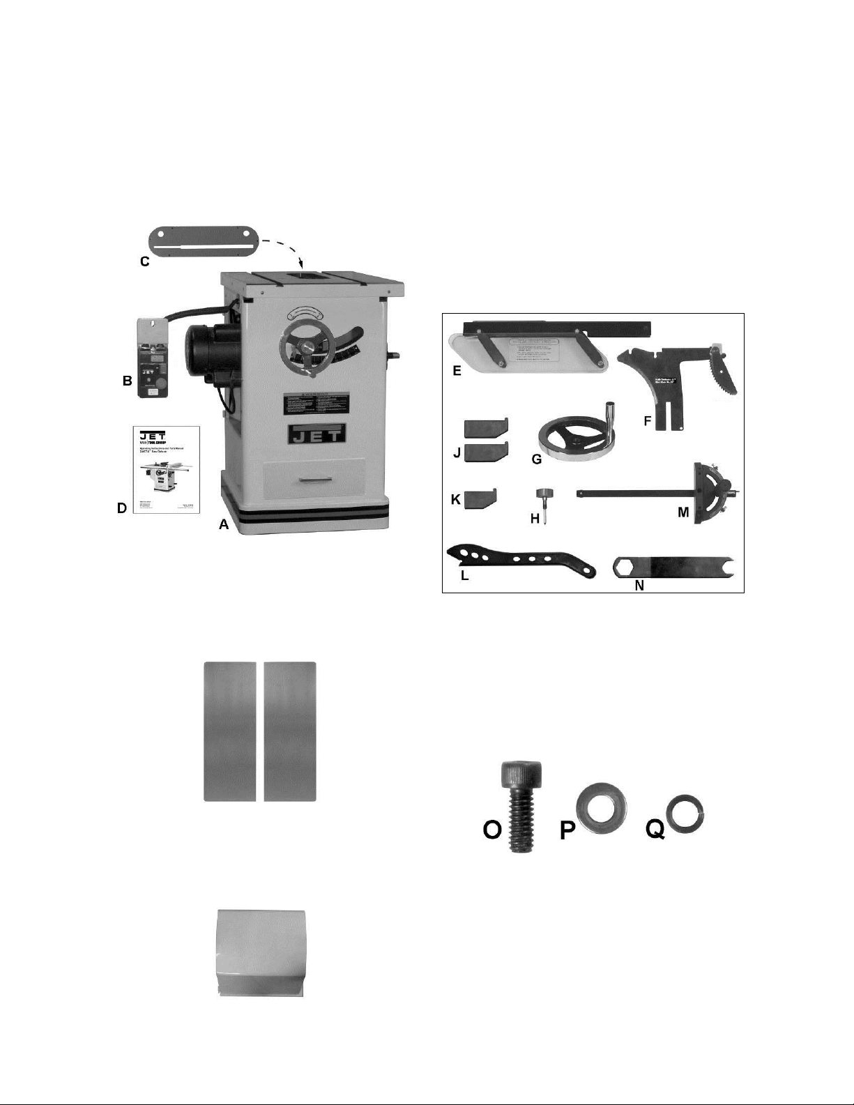
Contents of the Shipping Containe
r
Main Saw Container
1 Table Saw (A)
1 Switch (B)
1 Table Insert (C)
1 Owner's Manual (D)
1 Warranty Car d (not shown)
Small Box
The small box consists of the following items:
1 Blade Guard Assembl y (E)
1 Riving Knife and Pawl A ssembly (F)
1 Handwheel and Swivel Handle (G)
1 Lock Knob (H)
2 Large Hook (J)
1 Small Hook (K)
1 Push Stick (L)
1 Miter Gauge Assembly ( M)
1 27mm Arbor Wrench (N)
Main Saw Container
Extension Tables
Two extension tables are packaged in individual
boxes.
Extension Tables
Side Cover Box
1 Side Cover
Contents of Side Cover B ox
Contents of the Sm all B ox
Hardware
6 1/4 x 5/8 Socket Head Cap Screw (O)
6 1/4 Flat Washer (P)
6 1/4 Lock Washer (Q)
Contents of Hardw ar e B ag
8
Page 9
Assembly
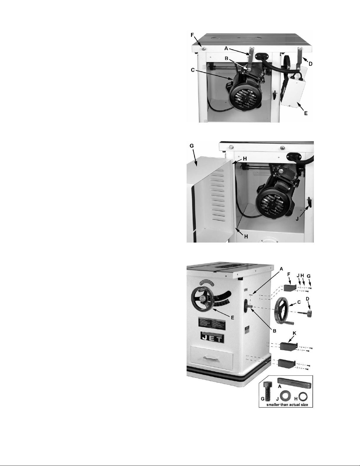
Moto r Cover
Referring to Fi gur es 1 and 2:
Tools: 17mm Wrench, 12mm Wrench
1. Remove shipping bracket (A) securing the
motor (C) to table.
2. After the shipping bracket has been removed,
install the screw (B) back into the motor
support bracket . The upper screws wil l be used
to later to hold the extension wing in place.
3. Remove shipping bracket (D) holding switch
assembly (E) to table. Do not discard the
bracket (D); it will be used to install the switch.
4. Remove the remaining hex cap screw, lock
washer, and flat washer (F and Fig. 5) in the
table edge.
5. Install motor cover (G) by aligning t he pins (H)
on the cover with brackets on the cabinet.
6. Fasten cover by pulling out the latch (J),
closing the door , and releasing the latch.
Figure 1
Handwheel Assembly
Referring to Fi gur e 3:
Hardware: (2) Handle & Handwheel (C),
(2) Lock Knob (D), (2) Shaft Key (A)
Tools: 3mm hex wrenc h
The f ront handwheel (E) is instal led at the factory.
Install the side handwheel (C) as follows:
1. Line up the key (A) (taped to shaft) on the
shaft (B) with the key way in the handwheel (C)
and slide the handwheel ont o the shaft.
2. Tighten the set screw on the handwheel hub
(3mm hex wrench) securely to hold in place.
3. Install the center lock knob (D) by inserting into
center hole in the shaft and threading in a
clockwise dir ec tion.
4. Install the remaining handwheel assembly (E)
in the same manner.
Miter Gauge and Fence Storage Hooks
Referring to Fi gur e 3:
Hardware: (1) Small Hook (F) , (2) Large Hook (K),
(6) 1/4” Flat Washers (J), (6) 1/4" Lock Washers
(H), (6) 1/4 x 5/8 Socket Head Cap Screws (G)
Tools: 5mm hex wrench
Mount the small hook (F) and two large hooks (K)
to the side of the saw cabinet with six eac h
socket head cap screws (G), 1/4" lock washers (H)
and 1/4" flat washers (J). Tighten with hex wrench.
1/4 x 5/8
Figure 2
Figure 3
9
Page 10

Extension Wing
Referring to Fi gur es 4 and 5:
Hardware: (6) 7/16”x1-1/2” Hex Cap Bolts, (6) 7/16”
Lock Washers, (6) 7/16” Flat Washers & (2)
Extension Wings
Tools: 17mm Wrench, Straight Edge
1. Attach the left extension wing (A) to the
table (B) with three each hex cap screws (E),
lock washers (F) and flat was her s (G). Snug so
the extension wing can still be manually
adjusted but do not tighten.
2. Adjust the extension wing horizontally so the
front edge is flush with the front edge of the
saw table (C). T hen, using the str aightedge as
reference, adjust vertically so the tops of the
extension wing and saw table ar e flush.
3. Tighten the three extension wing mounting
screws.
4. Remove the mounting hardware (Fig. 5) from
the table on the right side; then attach the right
extension wing in the same manner.
Figure 4
Blade Installation/Replacement
Use care when working with or
around sharp saw blad e to preven t inju ry!
To install or replac e a blade ( r efer to Figure 6):
Tools: 27mm Wrench
1. Disconnect machine from power source.
2. Raise the blade height all the way up and set
the blade tilt to 0º (refer to Handwheel
Adjustments on page 14).
3. Remove the table insert.
4. Rotate t he arbor to l ine up the slot (C) with the
arbor lock (D).
5. Press the ar bor lock (D) in t he direct ion shown
by the arrow to engage it i nto the slot (C) in the
arbor. At the same time remove the arbor
nut (A), loosening with a 27mm wrench if
necessary.
6. Remove the collar (B).
7. Install the blade, maki ng sure the cutti ng teeth
at the top of the blade poi nt toward the f ront of
the saw. If unsure, refer to Figure 8 for the
proper blade orientation.
8. Replace the collar (B) and arbor nut (A).
9. Engage the arbor lock (D) and ti ghten the nut
(A) with a 27mm wrench.
10. Lower the blade below the table.
Figure 5
Figure 6
10
Page 11

Riving Knife and Guard Installation
Description
Referring to Fi gur e 7:
The complete riving knife and guard assembly is
shown in A. Before installing onto the sa w, t he anti-
kickback pawl (E) must be separated from the
riving knife (H) as follows:
1. Press and hold t he quick-release but ton (D) on
the base of the anti-kickback pawl (E) and lift
the pawl to remove from the riving knife (H).
Inst a lla tion
Referring to Fi gur e 8:
2. Set the saw blade to the 90 degree position
and raise it all the way (refer to Handwheel
Adjustments on page 13).
3. Remove the table insert (J).
4. Located inside the table and accessible
through the insert opening (Figure 8 inset),
place the quick-release clamp lock handle (K)
in the unlock position.
5. The floating clamp block (L) is spring loaded
and will move away (O) from the fixed
block (M), leav ing a gap.
6. Insert the bot tom of the r iv ing knif e (N1, N2) all
the way int o the gap bet ween t he clamp b lock s
(L, M); then lock the handle (K).
7. Replace the insert (J) back on the table. The
saw blade and riving knife should protrude
through the slot in the insert.
Figure 7
Referring bac k to Figure 7:
8. Attach the anti-kickback pawl (E) by pressing
and holding the quick-release button (D) and
inserting the lock pin of the pawl into the
appropriate sl ot (F) on the riving knife.
9. In similar manner attach the guard (C) by
pressing and holding the quick-release button
(B) and inserting t he lock pin of the guard into
the appropriate slot (G) on the riving knife.
You should feel a snap as each piece locks in
position. Attempt to lift as a test to make sure that
they are securely loc k ed in plac e.
Adjustment
The clamping bloc ks (L, M, Fig. 8) are adjusted at
the factor y and no further adj ustment of the bl ade
guard and riving knife assembly should be
necessary. However, proper alignment is very
important. Before operating the table saw, read
Riving Knife Adjus tment (p.14) to v erify and follow
the adjustment pr oc edur e if necessary .
Figure 8
11
Page 12

Mounting Rails & Extension Table
Electrical Connections
With the extension wings properly aligned, the
rail and fence assembl y can now be mount ed to
the saw. Refer to the XACTA
Commercial 30/50 Owner's Manual (Part No.
M-708950Z) for mounting instructions for the
rails, fence and optional wooden extension
table.
Fence II
Switch Installation
Referring to Fi gur e 9:
Hardware: Switch Brace
Tools: 8mm hex wrench, 8mm wre n c h
1. Remove the hex nut from the flat head
screw that secures the left extension table to
the front rail (B).
2. Place switch assembly bracket (A) behind
the front rail (B) and just inside the front
edge of the left ext ens ion wing.
3. Repl ace the hex nut, securing t he front rail,
extension t able and switch assem bly. Handtighten only at t his tim e.
4. Loosen the hex cap screw (C) and slide the
open tab of the switch brace (E) onto the
screw (C) and washer (D). Hand-tighten only
at this time.
5. Remove the nut and star washer (F) from
the screw at t he bottom of t he switch plate
on the back of the switch assembly.
6. Fasten the switch brace to the switch
bracket assembly with the star washer and
nut.
7. Align the switch and tighten all hardware.
A qualified electrician must
complete all electrical connections! Failure
to comply may result in serious injury!
The machine must be
properly grounded while in use to protect the
operator from electric shock! Failure to
comply may result in serious injury!
If a plug i s provided with your m achine, do not
modify the plug. If it will not fit your electrical
receptacle, hav e a qualifi ed elect rician install the
proper connections to meet all electric al codes.
XACTA
numbers 708674 and 708676 are r ated at 230V
only. Saws with stock number 708680 ar e r ated
at 230/460V, and come from the factory
prewired 230V.
To switch from 230V to 460V (machines with
stock number 708680 only):
1. Disconnect the machine from the power
2. Open the saw cabinet door.
3. Remove the cover from the motor junction
4. Change wires following the diagram on the
5. Replace the cover and close the cabinet
6. Repl ace the m agnetic on-off switch wit h part
Saw Deluxe table saws with stock
source, (unplug).
box.
inside of the cover .
door.
#JTAS10-23B (available through your
authorized J ET distributor or by calling JET
at the number on the cover ).
Figure 9
Confirm power at the site is the same as the saw
before making any electrical connections.
Review the electrical schematics on page 27-27.
The on and off switch is th ermally protect ed. If
the saw motor is overloaded, or a momentary
interruption of electrical current is sensed, the
saw will shut off. Allow a few minutes for the
saw to cool do wn and reset by pushing the off
button.
Using extension cords can cause a loss in
power to your m achine. It i s best if the saw is
plugged directly into an outlet on a dedicated
circuit.
12
Page 13

Adjustments
Handwheel Adjustments
Referring to Fi gur e 10:
The front handwheel (B) controls the raising and
lowering of t he blade ( blade height).
The side handwheel ( D) control s the blade t il t. The
blade can be adjusted for a tilt between 90º
(vertical or a set ti ng of 0º on t he scale) and 45º l eft
tilt (D).
Blade height
1. Loosen the lock knob (A) on the front
handwheel (B).
2. Turn the handwheel (B) clock wise to raise and
countercl oc k wise to lower the blade.
3. Tighten the lock knob (A).
Blade tilt adjustment
1. Loosen the lock knob (C) on the side
handwheel (D).
2. Turn the handwheel (D) counterclockwise to
adjust the saw blade do wn to 45º left tilt. Turn
clockwise to adj ust the saw blade to m aximum
of 90º.
Figure 10
3. After selecting the position, tighten the lock
knob (C).
Insert Adjustment
Adjust the setscrews in the insert with a 2.5mm hex
wrench (Figure 11) to ensure that the insert is
stable and fl ush with the table top.
Miter Gauge
Referring to Fi gur e 12:
1. Operate miter gauge by loosening the lock
knob (A) and turni ng the miter body (B) to the
desired angle. To move gauge beyond index
stops of 45 and 90, flip down the stop (C).
2. Adjust index stops by turning one of three
adjustment screws (D).
Note: Always make test cuts. Do not rely solely on
miter gauge indi cator m arks. T here are holes i n the
miter gauge body that will allow you to mount a
wooden extension fence.
Figure 11
Figure 12
13
Page 14

Riving Knife Adjustment
Lateral alignment
The saw blade and riv ing knife must be in line as
close as possible with each other (lateral
alignment) for the prevention of kickback. Upon
initial blade guard and riving knife installation no
further adj ustment should be necessary. Ali gnment
should be checked an d adjusted, if r equired, after
each blade change.
Check the alignment as follows:
1. Remove the blade guard and pawl (C, E,
Fig. 7).
2. Place a straightedge (A, Fig. 13) on the table
so it rests against the blade (B, Fig 13) and
riving knife (C, Fig. 13). Rotate the blade so the
top of the blade tooth touches the straightedge.
The saw blade and rivi ng k nife must be in line.
If adjustm ent is requi r ed:
3. Remove the table insert.
4. Loosen the lock handle (A, Fig. 14) and
remove the riving knife, making a note as to
which direction the riving knife needs to be
moved to align it wit h the saw blade.
5. Using a 3mm hex wrench, make adjustments
to any of the four set screws (D, Fig. 15)
accessible through openings located in the
corners of the floating clamp block (E, Fig. 15).
6. If necessary, repeat the above procedure.
Figure 13
Figure 14
Figure 15
14
Page 15

Blade Alignment
Tools: 8mm hex wrench, combination square,
marker
Blade alignment with the table is adjusted at the
factory. Aft er a period of use, or, after moving the
saw to another location, the blade may no longer
be aligned wit h the t able.
To check and align the blade ( r efer to Figure 16):
1. Disconnect the saw fr om the power source.
2. Raise the blade guard up a way fr om the blade.
3. Choose a tooth on the far side of the blade
(towards the rear) and position the tooth
slightly above the table insert. Mark the tooth
with a marker. Measure the distance from the
side of the bl ade to the ri ght T-slot edge using
a combination square. Make sure to measure
between the teet h not on t he toot h (Figur e 16) .
4. Rotate the blade toward the front so that the
marked tooth i s just above the insert. M easure
the distance from the side of the blade to the
right T-slot edge. The two measurements
should be the same.
Figure 16
5. If they are not the same, loosen four hex
socket cap screws (A, Fig. 17) that hold the
table to the base. T wo are shown in Fi gur e 17.
6. Make the needed adj ustments and tighten the
four hex socket cap screws firmly.
7. Check the alignment once again after
tightening har dware.
Adjusting 45 and 90 Positive Stops
The stops hav e been adjusted at the fact ory. After
a period of use, or, after moving the saw to another
location, the stops may no longer be set properly.
To check and adjust the stops:
Tools: 12mm wrench, combination square
1. Disconnect saw f r om power source.
2. Raise the saw blade to its maximum height
using the handwheel.
3. Set the blade at 90 degrees to the table by
turning the blade tilting handwheel clockwise
as far as it will go.
Figure 17
4. Place a combination square on the table
against the blade and check to see that the
blade is at a 90 angl e to the tabl e, Figure 18.
Make sure square is not touching a blade
tooth.
Figure 18
15
Page 16

5. If blade is not at 90 degrees, open the motor
cover door, loosen lock nut (A, Fig. 19) and
turn adjusting stop screw (B, Fig. 19) on the
front trunnion in, or out. The adjusting stop
screw should stop against the front trunnion
bracket when the blade is 90 to the table.
6. Tighten the lock nut (A, Fig. 19).
7. Set the blade at 45 degrees to the table by
turning the blade tilting handwheel counterclockwise as far as it will go. Place a
combination square on the table against the
blade. Make sure square is not touching a
blade tooth.
8. If the blade is not 45 degrees, remove the
raising and lowering handle. Loosen lock nut
(A, Fig. 19) and turn adjusting stop screw
(B, Fig. 19) on t he front t r unnion in, or out. The
adjusting stop screw should stop against the
front tr unnion bracket when the blade i s 45 to
the table.
9. Check t he accuracy of t he pointer (C, Fig. 20)
on the angle scale and adjust, if necessary.
Assembly and adjustment of the saw are now
complete. Make sure all f asteners are tight . The
saw may now be placed into operation.
Changing the Belt
Figure 19
Figure 20
Make all machine adjustments
or maintenance with the machine unplugged
from the power source. Failure to comply may
cause serious inj ury!
Referring to Fi gur e 21:
1. Disconnect the machine from the power
source, unplug.
2. Lower the blade to its l owest point.
3. Loosen two hex cap bolt s (A).
4. Take the t ension off of t he belt (B) by l ifti ng up
on the motor.
5. Remove the belt from the arbor and motor
pulleys.
6. Replace and ten sion the belt. The weight of the
motor should appl y enough tension to the bel t.
Tighten the hex cap bolts (A).
7. Check t he belt tension after the saw has been
used for a few hours. Adj ust as necessary .
Figure 21
16
Page 17

Maintenance
Always disconnect power to the machine before performing maintenance. Failure
to do this may result in serious personal injury.
Cleaning
Note: The following maintenance schedule
assumes the saw is being used every day.
Daily:
Wipe down the table surface and grooves
with a rust prev entive.
Clean pitch and resin from the saw blade.
Weekly:
Table surface must be k ept clean and free of
rust for best results. Apply a coat of paste
wax to the surface to facilitate this.
Alternatively, aerosol protectants are
available from har dware and tool stores.
Clean motor housing with compressed air.
Wipe down the fence rails with a dry silicon
lubricant.
Periodic:
Keep the inside of the cabinet and trunni on
area clean.
Check for excessive play in the tilting and
raising mechani sm and in the saw arbor and
re-adjust as requir ed.
Check for belt tension and wear. Readjust or
replace belt as required.
Lubrication
Grease the tilting worm gear, raising worm
gear, castor system worm gear and the
trunnion areas with a good grade of nonhardening grease.
Check all adjustm ents after lubricati ng.
Miscellaneous
Routinely chec k condi tion of the following items:
Mounting bolts
Power switch
Saw blade
Blade guard assembly
17
Page 18

Troubleshooting
Trouble Possible Cause Solution
Saw stops or will
not start
Overload tripped
Saw unplugged from wall or m otor
Fuse blown or circuit breaker tripped
Cord damaged
Allow motor to cool and reset by
pushing off switch
Check all plug connections
Replace fuse or reset circuit breaker
Replace cord
Does not make
accurate 45 or
90 cuts
Material binds
blade when
ripping
Saw makes
unsatisfactory
cuts
Blade does not
come up to
speed
Saw vibrates
excessively
Stops not adjusted cor r ec tly
Angle pointer not set accurately
Miter gauge out of adj ustm ent
Fence not ali gned with blade
Warped wood
Excessive feed rate
Splitter not ali gned with blade
Dull blade
Blade mounted backwards
Gum or pitch on blade
Incorrect blade for cut
Gum or pitch on table
Extension cord too light or too long
Low shop voltage
Motor not wired for correct voltage
Stand on uneven fl oor
Damaged saw blade
Bad V-belts
Bent pulley
Improper motor mounting
Loose hardware
Check blade with square and adjust
stops
Check blade with square and adjust
pointer
Adjust miter gauge
Check and adjust fenc e
Select another piece of wood
Reduce feed rate
Align splitter with blade
Sharpen or replac e blade
Turn blade around
Remove blade and clean
Change blade to corr ec t t y pe
Clean table
Replace with adequat e si z e c or d
Contact your loc al elec tric company
Refer to motor junction box
Reposition on flat, level surface
Replace saw blade
Replace V-belts
Replace pulley
Check and adjust mot or
Tighten har dware
Rip fence binds
on guide rails
Material kicked
back from blade
Blade does not
raise or tilt freely
Guide rails or ext ensi on wing not installed
correctly
Guide of rip fenc e not adjusted properly
Rip fence out of alignm ent
Splitter not ali gned with blade
Feeding stock without rip fence
Splitter not in plac e
Dull blade
Letting go of material before it is past
blade
Anti-kick bac k plates dull
Sawdust and debris in raising and tilting
mechanisms
Re-assemble guide rails, refer to fence
manual
Adjust guides, refer to fence manual
Align rip fenc e with miter slot
Align splitter with blade
Install and use rip fence
Install and use splitter (with guard)
Replace blade
Push material all the way past blade
before releasi ng work
Replace or sharpen anti-kick back
plates
Clean and re-grease
18
Page 19

Optional Accessories
Stock No Description
708097 Dado Insert
708118 Universal Mobile Base
708295 Tenoning Jig
708401 Downdraft Table f or XACTA Delux e
708682 Riving Knife Thi n Kerf
708683 Riving Knife Low Profile
708684 Riving Knife Low Profile Thin Kerf
Parts
Ordering Replacement Parts
Replacement par ts are li sted on the f ollowing page s. To order parts or reac h our servi ce depar tm ent, call
1-800-274-6848, Mon day t hrough Fr iday (see our web sit e f or busi ness hours, www.j ett ool s.com). Havi ng
the Model Num ber and S eri al Num ber of y our machi ne avail abl e when you cal l will allow us to serve you
quickly and acc ur ately.
19
Page 20

Table & Cabinet Parts List
Index No. Part No. Description Size Qty
1 ............... JTAS10-1 .................Lock Knob ............................................................................................. 1
2 ............... JTAS10-2 .................Miter Gauge Body.................................................................................. 1
3 ............... TS-1540031 .............Hex Nut ..............................................................M5 .............................. 3
4 ............... JTAS10-4 .................Pointer................................................................................................... 1
5 ............... JTAS10-5 .................Stop Link ............................................................................................... 1
6 ............... TS-1521011 .............Socket Set Screw ...............................................M4x4 .......................... 1
7 ............... JTAS10-7 .................Special Pin .........................................................M3x6 .......................... 1
8 ............... TS-2205201 .............Hex Cap Scre w ..................................................M5x20 ........................ 3
9 ............... JTAS10-9 .................Guide Bar .............................................................................................. 1
10 ............. JTAS10-10 ...............Guide Washer ....................................................................................... 1
11 ............. JTAS10-11 ...............Flat Head Screw .................................................M6x8 .......................... 1
................. JTAS10-M G .............Miter Gauge Assembly (#1-11) .............................................................. 1
12 ............. TS-0267041 .............Soc ket Set Screw ...............................................1/4-2 0x3/8 .................. 6
13 ............. JTAS10L-13N ..........Tab le In sert ........................................................................................... 1
13A .......... 708097 ....................Dado Insert - ( Optional Accessory) ........................................................ 1
14 ............. JTAS10L-14WN .......Table ..................................................................................................... 1
15 ............. JTAS10L-15WN .......Extension Wing ..................................................................................... 2
18 ............. TS-0061051 .............He x Cap S cr e w ..................................................7/16 -1 4 x1 -1 /2 ............. 6
19 ............. TS-0720101 .............Lo ck Was h e r ......................................................7/16 ............................ 6
20 ............. TS-0680051 .............Flat Washer ........................................................7/16 .......................... 10
22 ............. JTAS10-22W ...........Switch Plate .......................................................................................... 1
23 ............. JTAS10-23 ...............Magnetic Switch .................................................3HP, 230V, 1 Ph ......... 1
................. JTAS10-2 3A ............Magnetic Switch .................................................5HP, 230V, 3 Ph ......... 1
................. JTAS10-2 3B ............Magnetic Switch .................................................5HP, 460V, 3 Ph ......... 1
................. JTAS12-2 3 ...............Magnetic Switch * ..............................................5HP, 1 Ph, 230V ......... 1
24 ............. TS-081C052 ............Pan Head Screw ................................................#10-24x3/4 ................. 1
26 ............. JTAS10-26 ...............Strain Relief Bushing ..........................................708674, PG-11 ........... 2
................. JTAS10-26A ............Strain Relief Bushing ..........................................708676, PG13.5 ......... 2
................. JTAS10-26B ............Strain Relief Bushing ..........................................708680, MG25A-16B . . 2
27 ............. JTAS10-27 ...............Strain Relief Bushing ..........................................708674, 6N3-4............ 2
................. JTAS10-27A ............Strain Relief Bushing ..........................................708676, 7N-2.............. 2
................. JTAS10-27B ............Strain Relief Bushing ..........................................708680, 8R3 ............... 2
28 ............. JTAS10-28 ...............Tap Screw ..........................................................M5x10 ...................... 10
29 ............. JTAS10-29 ...............Cord Plate ..........................................................708674, 14x16............ 1
................. JTAS10-2 9A ............Cord Plate ..........................................................708676, 15x17............ 1
................. JTAS10-2 9B ............Cord Plate ..........................................................708680, 17x21............ 1
30 ............. JTAS10L-30N ..........Identification Plate ................................................................................. 1
31 ............. JTAS10DX-31 ..........Power Cord (switch to motor,3HP 1PH 230V) .....14AWGx3C,SJT,300V 1
................. JTAS10DX-31A........Power Cord (switch to motor,5HP 1PH 230V) .....12AWGx3C,SJT,300V 1
................. JTAS10DX-31B........Power Cord (switch to motor,5HP 3PH 230/460V)14AWGx4C,ST,600V. 1
32 ............. JTAS10DX-32 ..........Power Cord (3HP 1PH 230V) .............................14AWGx3C,SJT,300V 1
................. JTAS10DX-32A........Power Cord (5HP 1PH 230V) .............................12AWGx3C,SJT,300V 1
................. JTAS10DX-32B........Power Cord (5HP 3PH 230/460V) .......................14AWGx4C,ST,600V .. 1
33 ............. JTAS10-33 ...............Power Cord Sleeve (708674) ..............................Ø19 ............................ 1
................. JTAS10-33A ............Power Cord Sleeve (708676,708680) .................Ø22 ............................ 1
34 ............. JTAS10L-34 .............Tilt Scale ............................................................................................... 1
35 ............. JTAS10-35 ...............Warning Label ....................................................................................... 1
36 ............. JTAS10-36 ...............JET Label .............................................................................................. 1
38 ............. JTAS10L-38WN .......Cabinet.................................................................................................. 1
39 ............. TS-1482101 .............He x Cap S cr e w ..................................................M6x50 ........................ 1
40 ............. TS-0680021 .............Fla t Washer ........................................................1/4 .............................. 2
41 ............. JTAS10-41 ...............Spring.................................................................................................... 1
42 ............. JTAS10-42 ...............Foam Strip............................................................................................. 1
43 ............. JTAS10L-43WN .......Motor Cover .......................................................................................... 1
44 ............. TS-1540021 .............Nylon Insert Lock Nut .........................................M6 .............................. 1
45 ............. JTAS10-45 ...............Handle................................................................................................... 1
20
Page 21

Table and Cabinet Parts List
Index No. Part No. Description Size Qty
47 ............. TS-0210011 .............Socket Head Cap Screw .....................................7/16-14x3/4 ................ 4
48 ............. TS-0680011 .............Flat Washer ........................................................3/16 ............................ 2
49 ............. JTAS10L-49WN .......Lower Panel .......................................................................................... 1
50 ............. JTAS10L-50N ..........Dust Hose Adapter ................................................................................ 1
51 ............. JTAS10-52W ...........Switch Brace Kit ** ................................................................................ 1
52 ............. TS-081C062 ............Screw .................................................................#10-24x1 .................... 1
53 ............. TS-0560071 .............Hex Nut ..............................................................#10-24 ........................ 1
54 ............. TS-0733031 .............Star Wash er .......................................................#1 0 ............................. 1
55 ............. JTAS10L-55 .............Hook ..................................................................................................... 2
56 ............. TS-0680021 .............Fla t Washer ........................................................1/4 .............................. 6
57 ............. TS-0720071 .............Lo ck Was h e r ......................................................1/4 .............................. 6
58 ............. TS-0207031 .............Socket Head Cap Screw .....................................1/4-20x5/8 .................. 6
59 ............. JTAS10L-59 .............Hook ..................................................................................................... 1
60 ............. TS-0561011 .............Hex Nut ..............................................................1/4-20 ......................... 6
61 ............. JTAS10L-61 .............Electrical Bo x......................................................................................... 1
62 ............. JTAS10L-62 .............Draw er .................................................................................................. 1
63 ............. JTAS10L-63 .............Handle................................................................................................... 1
64 ............. TS-1550031 .............Fla t Washer ........................................................M5 .............................. 2
65 ............. TS-0720051 .............Lo ck Was h e r ......................................................#10 ............................. 2
66 ............. TS-081C032 ............Pan Head Screw ................................................#10-24x1/2 ................. 2
* 10” saws with 5HP, 1Ph motor uses these parts.
** Switch Brace kit c ontains bracket, screw, nut, star washer, and 8m m hex wrench.
21
Page 22

Table & Cabinet Exploded View
1
2
)(
3
3
4
)(
6
)
3(8
9
10
12
13
13A
(optional)
11
5
6
14
)(
428
15
18
7
(
)
2
)
(
6
)
19(6
20 (6)
61
49
45
44
42
43
40
41
40
63
39
29
30
34
36
64(2)
28(2)
65(2)
66(2)
60(6)
62
35
38
55(2)
20 (4)
47
56(6)
(
4
)
28(4)
50
59
58(6)
57(6)
22
Page 23

Trunnion & Motor Parts List
Index No. Part No. Description Size Qty
101 ........... JTAS10L-101 ...........Arbor Nut ............................................................................................... 1
102 ........... JTAS10-102 .............Arbor Flange ......................................................................................... 1
104 ........... JTAS10L-104N ........Arbor with Flange .................................................................................. 1
105 ........... JTAS10-105 .............Key ....................................................................M5x44 ........................ 2
106 ........... BB-6203ZZ ..............Ball Bearing ........................................................6203ZZ....................... 2
107 ........... JTAS10-107 .............Wave Washer ........................................................................................ 4
108 ........... JTAS10-108 .............Rear Bearing Load Spacer .................................................................... 2
108-1 ........ JTAS10DX-108 ........Front Bearing Load Spacer .................................................................... 1
109 ........... TS-0267041 .............Socket Set Screw ...............................................1/4-20x3/8 ................ 10
110 ........... JTAS10-110N ..........Arbor Pulley ........................................................................................... 1
111 ........... TS-0209081 .............Socket Head Cap Screw .....................................3/8-16x1- 3/4 ............... 1
112 ........... JTAS10DX-112 ........Key.....................................................................1/4x1/4 x45.................. 1
113 ........... TS-0720091 .............Lock Was h e r ......................................................3/8 ............................ 1 0
114 ........... JTAS10DX-114 ........Arbor Bracket ........................................................................................ 1
115 ........... JTAS10-115 .............Spanner Nut .......................................................................................... 1
116 ........... JTAS10L-116 ...........Nut .....................................................................5/8 .............................. 1
117 ........... JTAS10-117 .............Spring Pin...........................................................M6 x50 ........................ 1
118 ........... JTAS10-118 .............Key.....................................................................1/4x1/4 x2-5/16............ 1
119 ........... TS-0680051 .............Flat Washer ........................................................7/16 ............................ 2
120 ........... TS-0091031 .............Hex Cap Scre w ..................................................7/16 - 1 4 x1 ................... 2
121 ........... JTAS10DX-121 ........Shaft ..................................................................................................... 1
122 ........... JTAS10-122 .............Motor Bracket ........................................................................................ 1
123 ........... JTAS10-123 .............Pin......................................................................................................... 1
124 ........... JTAS10-124 .............Spring Clip............................................................................................. 2
125 ........... JTAS10L-125N ........Poly V-Belt ......................................................... 260J ........................... 1
126 ........... JTAS10DX-126 ........Motor Mounting Bracket ......................................................................... 1
127 ........... JTAS10-127N
128 ........... TS-0680031 .............Flat Washer ........................................................5/16 .......................... 10
129 ........... TS-0720081 .............Lock Was h e r ......................................................5/16 ............................ 9
130 ........... TS-0081031 .............Hex Cap Scre w ..................................................5/16 - 1 8 x3/4 ................ 4
131 ........... JTAS10DX-131N .....Motor ..................................................................3HP, 1Ph, 230V only .. 1
................. JTAS10D X-131C .....Motor ..................................................................5HP, 1Ph, 230V only .. 1
................. JTAS10D X-131A ......Motor ..................................................................5HP, 3Ph, 230/460V ... 1
................. JTAS10D X-131CS ...Centrifugal Switch Assembly (not shown) .............................................. 1
................. JTAS10-131D ..........Fan Cover (not shown) .......................................................................... 1
................. JTAS10-131F ...........Motor Fan (not shown) ........................................................................... 1
................. C-600125 .................Start Capacitor (not shown) ................................3HP, 1Ph motor .......... 1
................. C-040250 .................Run Capacitor (not shown) .................................3HP, 1Ph motor .......... 1
................. JTAS10-1315B ........Start Capacitor (not shown) ................................5HP, 1Ph motor .......... 1
................. JTAS10-1315A ........Run Capacitor (not shown) .................................5HP, 1Ph motor .......... 1
132 ........... TS-0209071 .............Socket Head Cap Screw .....................................3/8-16x1- 1/2 ............... 6
133 ........... JTAS10DX-133 ........Rear Trunnion Bracket ........................................................................... 1
134 ........... TS-0561031 .............Hex Nut ..............................................................3/8-16 ......................... 5
135 ........... TS-0209051 .............Socket Head Cap Screw .....................................3/8-16x1 ..................... 4
136 ........... JTAS10-136 .............Spring Pin...........................................................M8 x25 ........................ 4
137 ........... TS-0561081 .............Hex Nut ..............................................................3/4-10 ......................... 1
138 ........... JTAS10-138 .............Fiber Wash e r ......................................................................................... 4
139 ........... JTAS10DX-139 ........Rear Trunnion ...................................................................................... 1
140 ........... JTAS10-140 .............Rear Bushing......................................................................................... 2
140-1 ........ JTAS10DX-140 ........Front Bushing ........................................................................................ 1
141 ........... JTAS10DX-141 ........Yoke ...................................................................................................... 1
142 ........... TS-0270011 .............Socket Set Screw ...............................................5/16-18x1/4 ................ 4
143 ........... JTAS10-143
144 ........... JTAS10DX-144 ........Shaft ..................................................................................................... 1
145 ........... JTAS10-145 .............Spring Pin...........................................................M5 x30 ........................ 2
146 ........... JTAS10-146 .............Worm (Left thread) ................................................................................ 2
146-1 ........ JTAS10DX-146 ........Worm (Right thread) .............................................................................. 1
147 ........... JTAS10-147 .............Lock Pin ................................................................................................ 4
148 ........... JTAS10-148 .............Key.....................................................................M5x35 ........................ 2
..........Motor Pulley .......................................................................................... 1
.............Collar .................................................................................................... 2
23
Page 24

Trunnion & Motor Parts List
Index No. Part No. Description Size Qty
149 ........... TS-0208041 .............Socket Head Cap Screw .....................................5/16-18 x3/4” ............... 4
150 ........... JTAS10L-150N ........Dust Deflector........................................................................................ 1
151 ........... JTAS10L-151N ........Hose Clamp .......................................................................................... 2
152 ........... JTAS10DX-152 ........Front Trunnion ....................................................................................... 1
................. JTAS10D X-TA .........Trunnion Assembly (#113, 135, 136, #139 t hr ough #141 and # 152) ...... 1
153 ........... TS-0051021 .............Hex Cap Scre w ..................................................5/16 - 1 8 x5/8 ................ 2
154 ........... TS-0561021 .............Hex Nut ..............................................................5/16-18 ....................... 2
155 ........... JTAS10-155A ..........Lock Knob ............................................................................................. 2
156 ........... JTAS10-156 .............Fiber Wash e r ......................................................................................... 2
157 ........... TS-0208061 .............Socket Head Cap Screw .....................................5/16-18 x1 ................... 2
158 ........... JTAS10DX-158 ........Front Trunnion Bracket .......................................................................... 1
159 ........... JTAS10-159 .............Hand Wheel Handle .............................................................................. 2
160 ........... JTAS10-160 .............Hand Wheel .......................................................................................... 2
161 ........... JTAS10-161 .............Shield Plate ........................................................................................... 1
162 ........... TS-0813022 .............Round Head Screw ............................................1/4-2 0x3/8 .................. 1
163 ........... JTAS10-163 .............Pointer................................................................................................... 1
164 ........... JTAS10-164 .............Pointer Brac ke t ...................................................................................... 1
165 ........... TS-081C102 ............Pan Head Screw ................................................#10-24x2 .................... 2
166 ........... JTAS10DX-166 ........Guide Block ........................................................................................... 1
167 ........... TS-0680041 .............Flat Washer ........................................................3/8 .............................. 1
169 ........... JTAS10DX-169 ........Tilt Shaft ................................................................................................ 1
170 ........... JTAS10L-170 ...........Wrench.................................................................................................. 1
171 ........... JTAS10L-171 ...........Hose ..................................................................700mm ....................... 1
172 ........... JTAS10L-172 ...........Plate ...................................................................................................... 1
173 ........... TS-0208041 .............Socket Head Cap Screw .....................................5/16-18 x3/4 ................ 3
174 ........... JTAS10L-174
175 ........... TS-0680011 .............Flat Washer ........................................................3/16 ............................ 3
176 ........... TS-0720051 .............Lock Was h e r ......................................................#10 ............................. 3
177 ........... JTAS10L-177 ...........Hex Cap Bolt ......................................................#10-24x3/8 ................. 3
178 ........... JTAS10L-178 ...........Special Screw........................................................................................ 1
179 ........... JTAS10L-179A ........Arbor Lock Insert Assembly (#179-1through #179-5) ............................. 1
179-1 ........ JTAS10L-179-1 ........Arbor Lock Insert ................................................Ø8 .............................. 1
179-2 ........ JTAS10L-179-2 ........Spring.................................................................................................... 1
179-3 ........ JTAS10L-179-3 ........Insert Bracket ........................................................................................ 1
179-4 ........ TS-1502051 .............Socket Head Cap Screw .....................................M5 x 20 ...................... 2
179-5 ........ TS-1521041 .............Socket Set Screw ...............................................M4 x 10 ...................... 1
180 ........... JTAS10L-180 ...........Spring.................................................................................................... 1
181 ........... TS-0640071 .............Nylon Insert Lock Nut .........................................1/4-20 ......................... 3
182 ........... JTAS10L-182N ........Space r................................................................................................... 2
183 ........... JTAS10L-183 ...........Guide Bracket........................................................................................ 1
184 ........... TS-0245051 .............Flat Head Socket Screw .....................................1/4- 20x1 ..................... 2
185 ........... JTAS10L-185 ...........Special Screw........................................................................................ 1
186 ........... JTAS10L-186 ...........Extension Support Plate ........................................................................ 1
187 ........... TS-1541021 .............Nylon Insert Lock Nut .........................................M6 .............................. 1
188 ........... JTAS10L-188 ...........Plate ...................................................................................................... 1
189 ........... JTAS10L-189A ........Riving Knife Extension Plate .................................................................. 1
190 ........... TS-1513021 .............Flat Head Socket Screw .....................................M5x12 ........................ 2
191 ........... JTAS10L-191 ...........Clamping Block ..................................................................................... 1
192 ........... JTAS10L-192 ...........Spring.................................................................................................... 1
193 ........... JTAS10L-193 ...........Clamping Block ..................................................................................... 1
194 ........... TS-1514031 .............Flat Head Socket Screw .....................................M6X 20........................ 2
195 ........... JTAS10L-195 ...........Locking Handle ...................................................................................... 1
196 ........... TS-1541031 .............Nylon Insert Lock Nut .........................................M8 .............................. 1
197 ........... JTAS10L-197 ...........Spring Shim Ring................................................................................... 1
198 ........... JTAS10L-198 ...........C-Ring ................................................................S52 ............................ 1
...........Chip Plate.............................................................................................. 1
24
Page 25

Trunnion & Motor Assembly Drawing
25
Page 26

Blade Guard Parts and Assembly
Index No. Part No. Description Size Qty
1 ............... JTAS10L-301 ...........Riving Knife .......................................................................................... 1
................. JTAS10D X-BGA ......Blade Guard Assembly (Index #2 thru #16, #21, #22) ............................ 1
2 ............... PM2000-302 ............Bushing ................................................................................................. 2
3 ............... JTAS10L-303 ...........Blade Guard Body ................................................................................. 1
4 ............... JTAS10L-304 ...........Blade Guard Si de Shi eld........................................................................ 2
5 ............... PM2000-305 ............Linking Plate .......................................................................................... 4
6 ............... TS-1550041 .............Flat Washer ........................................................M6 .............................. 8
7 ............... TS-1514021 .............Flat Head Socket Screw .....................................M6x16 ........................ 8
8 ............... PM2000-308 ............Front Shield ........................................................................................... 1
9 ............... PM2000-309 ............Bushing ................................................................................................. 1
10 ............. PM2000-310 ............Top Sight Shield .................................................................................... 1
11 ............. TS-1541021 .............Nylon Insert Lock Nut .........................................M6 .............................. 8
12 ............. TS-081B012.............Pan Head Screw ................................................#8-32 x1/4 ................... 2
13 ............. PM2000-313 ............Roll Pin...............................................................5x25 ........................... 1
14 ............. PM2000-314 ............Roll Pin...............................................................5x12 ........................... 2
15 ............. PM2000-315 ............Lock Pin ................................................................................................ 1
16 ............. PM2000-316 ............Roll Pin...............................................................4x28 ........................... 1
................. PM2000-AKPA .........Anti-Kickback Pawl Assembly (Index #17 thru #22) ............................... 1
17 ............. PM2000-317 ............Anti-Kickback Pawl ................................................................................ 2
18 ............. PM2000-318 ............Paw l Bas e ............................................................................................. 1
19 ............. PM2000-319 ............Flange ................................................................................................... 2
20 ............. PM2000-320 ............Lock Pin ................................................................................................ 1
21 ............. PM2000-321 ............Sprin g.................................................................................................... 2
22 ............. PM2000-322 ............E-Cl ip .................................................................E5 .............................. 2
26
Page 27

Wiring Diagrams for XACTA Deluxe Table Saws
3HP/5HP, 230V, 1Phase
27
Page 28

5HP, 230V, 3 Phase
28
 Loading...