

Page 1
Operating Instructions and Parts Manual
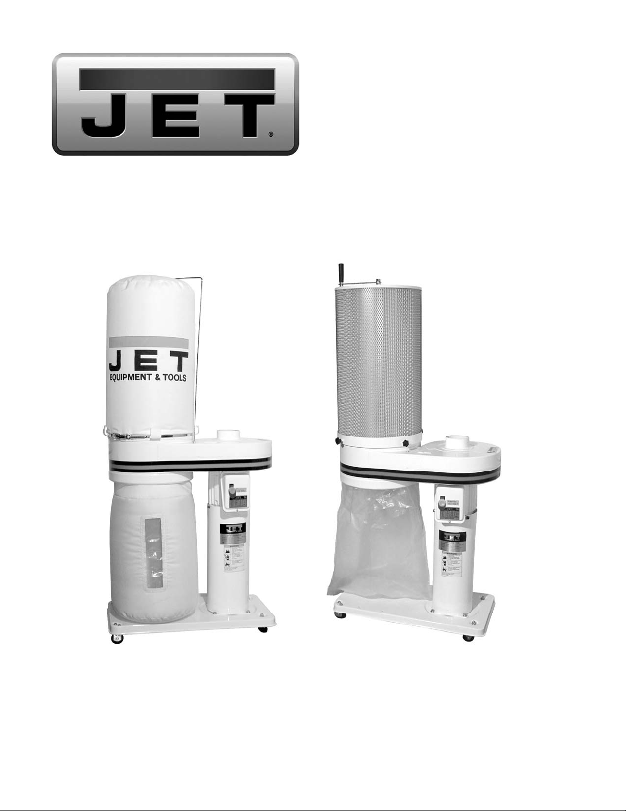
Dust Collector
Models: DC-650BK, DC-650CK, DC-650MK
DC-650BK shown DC-650CK shown
JET
427 New Sanford Road
LaVergne, Tennessee 37086 Part No. M-708642
Ph.: 800-274-6848 Revision D 08/2014
www.jettools.com Copyright © 2014 JET
Page 2

Warranty and Service
JET, Wilton and Powermatic warrants every product they sell against manufacturers’ defects. If one of our tools needs
service or repair, please contact Technical Service by calling 1-800-274-6846, 8AM to 5PM CST, Monday through Friday
Warranty Period
The general warranty lasts for the time period specified in the literature included with your product or on the official JET,
Wilton or Powermatic branded websites.
• JET, Wilton and Powermatic products carry a limited warranty which varies in duration based upon the product.
(See chart below)
• Accessories carry a limited warranty of one year from the date of receipt.
• Consumable items are defined as expendable parts or accessories expected to become inoperable within a
reasonable amount of use and are covered by a 90 day limited warranty against manufacturer’s defects.
Who is Covered
This warranty covers only the initial purchaser of the product from the date of delivery.
What is Co vered
This warranty covers any defects in workmanship or materials subject to the limitations stated below. This warranty does
not cover failures due directly or indirectly to misuse, abuse, negligence or accidents, normal wear-and-tear, improper
repair, alterations or lack of maintenance.
Warranty Limitations
Woodworking products with a Five Year Warranty that are used for commercial or industrial purposes default to a Two
Year Warranty. Please contact Technical Service at 1-800-274-6846 for further clarification.
How to Get Technical Support
Please contact Technical Service by calling 1-800-274-6846. Please note that you will be asked to provide proof of
initial p u rchase when calling. If a product requir es further inspection, the Technical Ser vi c e r epr esent a tive will explain
and assist with any additional action needed. JET, Wilton and Powermatic have Authorized Service Centers located
throughout the United States. For the name of an Authorized Service Center in your area call 1-800-274-6846 or use the
Service Center Locator on the JET, Wilton or Powermatic website.
More Informat io n
JET, Wilton and Powermatic are consistently adding new products. For complete, up-to-date product information, check
with your local distributor or visit the JET, Wilton or Powermatic website.
How S tate Law Appl ies
This warranty gives you specific legal rights, subject to applicable state law.
Limitations on This Warranty
JET, WILTON AND POWERMATIC LIMIT ALL IMPLIED WARRANTIES TO THE PERIOD OF THE LIMITED WARRANTY
FOR EACH PRODUCT. EXCEPT AS STATED HEREIN, ANY IMPLIED WARRANTIES OF MERCHANTABILITY AND
FITNESS FOR A PARTICULAR PURPOSE ARE EXCLUDED. SOME STATES DO NOT ALLOW LIMITATIONS ON HOW
LONG AN IMPLIED WARRANTY LASTS, SO THE ABOVE LIMITATION MAY NOT APPLY TO YOU.
JET, WILTON AND POWERMATIC SHALL IN NO EVENT BE LIABLE FOR DEATH, INJURIES TO PERSONS OR
PROPERTY, OR FOR INCIDENTAL, CONTINGENT, SPECIAL, OR CONSEQUENTIAL DAMAGES ARISING FROM THE
USE OF OUR PRODUCTS. SOME STATES DO NOT ALLOW THE EXCLUSION OR LIMITATION OF INCIDENTAL OR
CONSEQUENTIAL DAMAGES, SO THE ABOVE LIMITATION OR EXCLUSION MAY NOT APPLY TO YOU.
JET, Wilton and Powermatic sell through distributors only. The specifications listed in JET, Wilton and Powermatic printed
materials and on official JET, Wilton and Powermatic-branded websites are given as general information and are not
binding. JET, Wilton and Powermatic reserve the right to effect at any time, without prior notice, those alterations to parts,
fittings, and accessory equipment which they may deem necessary for any reason whatsoever. JET
not sold in Canada by JPW Industries, Inc.
Product Listing with Warranty Period
90 Days – Parts; Consumable items; Light-Duty Air Tools
1 Year – Motors; Machine Accessories; Heavy-Duty Air Tools; Pro-Duty Air Tools
2 Year – Metalworking Machinery; Electric Hoists, Electric Hoist Accessories
5 Year – Woodworking Machinery
Limited Lifetime – Wilton branded products; JET Parallel clamps; VOLT Series Electric Hoists;
Manual Hoists; Manual Hoist Accessories; Shop Tools; Warehouse & Dock products; Hand Tools
NOTE: JET, Wilton and Powermatic are divisions of JPW Industries, Inc.. References in this document to JET, Wilton
and/or Powermatic also apply to JPW Industries, Inc., or any of its successors in interest to the JET, Wilton and/or
Powermatic brands.
®
branded products are
2
Page 3

Table of Contents
Warranty and Servic e ...................................................................................................................................... 2
Table of Content s ............................................................................................................................................ 3
Warnings ...................................................................................................................... .................................. 4
Introduction ..................................................................................................................................................... 5
Specifications .................................................................................................................................................. 6
Unpacking ....................................................................................................................................................... 7
Shipping Contents ........................................................................................................................................... 7
Bag Filter Kits .............................................................................................................................................. 7
Base Unit .................................................................................................................................................... 7
Canister Filter Kit ......................................................................................................................................... 7
Tools Required for Assembly ....................................................................................................................... 7
Base Unit Assembly ........................................................................................................................................ 8
Motor Housing and Support Cylinder ........................................................................................................... 8
Base Assembly ............................................................................................................................................ 8
Mounting the Support Canister to Base ........................................................................................................ 8
Mounting the Inlet Guard Assembly ............................................................................................................. 9
Filter Bag Kit Assembly ................................................................................................................................... 9
Filter Bag Installation ................................................................................................................................... 9
Collector B ag Installation (30 Micron Kit) ...................................................................................................... 9
Collector Bag Installation (5 Micron Kit)........................................................................................................ 9
Canister Kit Assembly ................................................................................................................................... 10
Canister Filter Installation .......................................................................................................................... 10
Collector Bag Installation ........................................................................................................................... 10
Electri c al Connec tions ................................................................................................................................... 11
Turning th e Machine On & Off ....................................................................................................................... 11
All Models.................................................................................................................................................. 11
Remote Control (Optional) ......................................................................................................................... 11
Dust Collect or RF Remote P ower Cont r ol (Optional) ..................................................................................... 11
Turning the DC-RC On & Off ..................................................................................................................... 11
Changing Operating Frequency ................................................................................................................. 12
Installing the DC-RC Remote Power Control .............................................................................................. 12
Maintenance ................................................................................................................................................. 13
Cleaning the Filter Bag – DC-650BK/MK .................................................................................................... 13
Removing the Collector Bag – DC-650BK .................................................................................................. 13
Cleaning the Filter – DC-650CK ................................................................................................................. 13
Removing the Collector Bag – DC-650CK and DC-650MK ......................................................................... 13
Motor ......................................................................................................................................................... 13
Connecting the Dust Collector to a Machine............................................................................................... 13
Grounding the Dust Collection System ....................................................................................................... 13
Parts ............................................................................................................................................................. 14
Replacement Parts .................................................................................................................................... 14
Parts List – Base Machine ......................................................................................................................... 14
Parts Breakdown – Base Machine ............................................................................................................. 15
Canister Filter Assembly ............................................................................................................................ 16
30 Micron Filter Bag Assembly .................................................................................................................. 17
5 Micron Filter Bag Assembly .................................................................................................................... 18
Wiring Diagrams for DC-650 ......................................................................................................................... 19
3
Page 4

Warnings
1. Read and understand the ent ire owner's manual before attempting assembly or operation.
2. Read and understand t he warnings posted on the machine and in this manual. Failure to com ply wi th all of
these warnings may c ause serious i njury.
3. Replace the warning labels if they become obscured or remov ed.
4. This dust collector is designed and intended for use by properly trai ned and experienced personnel only. If
you are not famili ar with the proper and saf e operati on of a dust collect or, do not use unti l proper trai ning
and knowledge have been obtained.
5. Do not use this dust collector for other than its intended use. If used for other purposes, JET disclaims any
real or implied warranty and holds itself harmless f r om any injury that may result from that use.
6. Always wear approved safety glasses/face shiel ds while using this dust collector. Everyday eyeglasses
only have impact resi stant lenses; they are not saf ety glasses.
7. Before operating this dust collector, rem ove tie, rings, watches and other jewelry, and roll sleev es up past
the elbows. Remove all loose cl othing and confine long hai r. Non-sli p footwear or anti-skid fl oor strips are
recommended. Do not wear gloves.
8. Wear ear protector s (plugs or muffs) during ext ended periods of operation.
9. Some dust c reated by power sanding, sawing, grinding, drilling and other constructi on activities contain
chemicals known to cause cancer, birth defects or other reproductive harm. Some examples of these
chemicals are:
• Lead from lead based paint.
• Crystalli ne sil ic a from bricks, cement and other m asonry pr oduc ts.
• Arsenic and chromium from chemically treated lum ber .
Your risk of exposure vari es, depending on how of t en you do this type of work. To r educe your ex posure
to these chemic als, work i n a well -venti l ated area and work wit h approv ed saf ety equipment, such as f ace
or dust masks that are specif ically designed to filt er out mic r oscopic particles.
10. Do not operate this machine while tired or under the influence of dr ugs, alcohol or any medication.
11. Make certain the swit c h is i n the OFF position before connect ing the machine to the power supply.
12. Make certain the machine is properly grounded.
13. Make all machine adjustments or maintenance with the machine unplugged from the power source.
14. Remov e adjusting keys and wrenches. For m a habit of checki ng to see that keys and adjusting wrenches
are removed from the machine before turning it on.
15. Keep safety guards i n plac e at all times when the machine is in use. If rem ov ed for maintenance purposes,
use extreme caution and replace the guards immediately.
16. Check dam aged parts. B efore further use of the machine, a guard or other part that is damaged should be
carefully c hecked to determine that it will operate properly and perform it s intended f unction. Check for
alignment of moving parts, bi nding of moving parts, breakage of part s, mounting and any other conditions
that may affect its operation. A guard or other part that is damaged should be properly repaired or
replaced.
17. Provide for adequate space surrounding work area and non- glare, overhead lighting.
18. Keep the floor around t he m achine clean and free of scrap materi al, oil and grease.
19. Keep visitor s a safe distance from the work area. Keep child ren aw ay.
4
Page 5

20. Make your workshop chil d pr oof with padlocks, master switc hes or by r em ov ing starter keys.
21. Give your work undivided attention. Looking around, carrying on a conversation and “horse-play” are
careless acts that can r esul t in serious injury.
22. Do not use the dust col lector for anything except wood dust. Mat erials such as liquids, metal shavings,
metal dust, screws, glass, plasti c or rock can cause sparks and/or damage when coming into contact with
any part of the dust collector.
23. Use rec om mended accessories; i mproper accessories may be hazardous.
24. Maintain tools with c ar e. Follow instructions for lubricating and changing accessor ies.
25. Turn off the machine before cleaning. Use a brush or compressed air to r emove chips or debris — do not
use your hands.
26. Do not stand on the machine. S erious injury could occur if the mac hine tips over.
27. Never leav e the machine running unattended. Turn the power off and do not l eav e the machine until it
comes to a complete stop.
28. Remove loose item s and unnecessary work pieces from the area before starting the machine.
29. Never place hands near the inlet of the machine.
30. Always make certain machine is off and unplugged when making any connections to the inlet.
Familiariz e you rself with the following safety notices used in this manual :
This means that if precautions are not heeded, it may result in minor injury and/or possibl e
machine damage.
This means that if precautions are not heeded, it may result in serious injury or possibly ev en
death.
- - SAVE THESE INSTRUCTIONS - -
Introduction
This manual is provided by JET covering the safe operation and maintenance procedures for models
DC-650 Series Dust Coll ectors. This manual contains instructi ons on installation, safety prec autions, general
operating proc edures, maintenance instructi ons and parts breakdown. This machine has been designed and
constructed to provide years of trouble free operation if used in accordance to i nstructions set f orth in this
manual. If there are any questions or comments, please contac t either your local suppl ier or JET. JET can also
be reached at our website: www.jettools.com
Read and understand th e entire contents of this manual before attempting set-up or
operation ! Failure t o co mply may cause serious injury.
5
Page 6

Specifications
Base Machine with 30 micron Filter Bag Kit ............................................................................... 708642BK
Base Machine with 5 micron Filter Bag Kit ................................................................................. 708642MK
Base Machine with Canister Kit ................................................................................................. 708642CK
Base Machine (All Mod els):
Model ....................................................................................................................................... DC-650M
Stock Number ............................................................................................................................. 708642
Blower Wheel Diameter (in. ) ............................................................................................................ 9-1/2
Sound Rating at 3 feet .............................................................................................................. 65-70 dB
Hose Diameter (in.) ............................................................................................................................... 4
Air Flow at 4” (CFM): ......................................................................................................................... 650
Max. Static Pressure (inch of water): .................................................................................................. 6.5
Velocity at 4" (FPM) ........................................................................................................................ 6300
Motor ......................................................... TEFC, 1 HP, 1Ph, 115V/230V, Prewired 115V, 60Hz, 7/3.5A
Switch ............................................................................................... paddle styl e, removable safety key
30 Micron Filt er Bag Kit:
Stock Number ........................................................................................................................... 708642B
Filter Bag Efficiency ....................................................................................... 96% of 30 micron particles
Filter Bag Length (in.) .......................................................................................................................... 24
Filter and Collector Bag Diam eter (in.) ................................................................................................. 14
Collector Bag Length (i n.) .................................................................................................................... 23
Collector Bag Capacity (c u. ft.) ........................................................................................................... 2.1
5 Micron Filter Bag Kit:
Stock Number ........................................................................................................................ 708642MF
Filter Bag Efficiency ....................................98% of 5 micron particles; 92% of 3 micron; 74% of 1micron
Filter Bag Length (in.) .......................................................................................................................... 24
Filter and Collector Bag Diam eter (in.) ................................................................................................. 14
Collector Bag Length (i n.) .................................................................................................................... 23
Collector Bag Capacity (c u. ft.) ........................................................................................................... 2.1
Canister Fil t er Kit:
Stock Number .......................................................................................................................... 708737C
Canister Efficiency .................................................. 86% of 1 micron particles; 98% of 2 mic r on partic les
Canister Length (in.) ............................................................................................................................ 25
Collector Bag Diameter (in.) ................................................................................................................ 14
Collector Bag Length (i n.) .................................................................................................................... 23
Collector Bag Capacity (c u. ft.) ........................................................................................................... 2.1
Model DC-650BK DC-650MK DC-650CK
Overall Dimensions (in.) ............... 27L x 14W x 66H ............... 27L x 14W x 66H ............ 27L x 14W x 61H
Net Weight (lbs) ................................................. 62 ...................................... 62 ................................... 70
Gross weight (lbs) .............................................. 74 ...................................... 74 ................................... 87
RF Remote Control Unit (Optio nal Accessory)
Stock Number (Main unit and transmitter) (115V only) .............................................................. 708636C
Stock Number (Transmitter only) ............................................................................................... 708636T
The above specifications were current at the time this manual was published, but because of our policy of
continuous improvem ent, JET reserves the right to change specificat ions at any time and wit hout prior notice,
without incurring obligations.
6
Page 7

Unpacking
Shipping Contents (cont)
The table below lists the shipping cartons that are
included with the models of the DC-650 Dust
Colle ctor.
1. Locate your par ticular model and verify t hat you
have received t he all the c or r ec t car tons.
2. Check content s of each carton agai nst the ship-
ping content listings on this and the following
page.
3. Report any damage to y our di stri butor.
4. Do not discard any shipping material until after
the dust collector has been assembled and is
running properly.
Base Unit
DC-650BK x x
DC-650CK x x
DC-650MK x x
Filter Bag Kit
(Sto ck No 708642)
(Sto ck No 708642B )
Filter Bag Kit
Canister Filter Kit
(Sto ck No 708642MF )
(Sto ck No 708737C)
Table – DC-650 Dust Collector cartons
Shipping Contents
Bag Filter Kits
(Stock No. 708642B):
1 – Collector Bag
1 – Filter Bag
1 – Retaining Strap
1 – Filter Bag Support Rod
1 – Hardware Bag
1 – M6 Hex Nut
1 – M6 Flat Washer
1 – M6 Lock Washer
(Stock No. 708642MF ) :
1 – Collector Bag
1 – Snap Ring
1 – Filter Bag
1 – Retaining Strap
1 – Filter Bag Support Rod
1 – Hardware Bag
1 – M6 Hex Nut
1 – M6 Flat Washer
1 – M6 Lock Washer
(Stock No DC650-FHP)
(Stock No DC650-FHP)
Base Unit
(Stock No 708642)
1 – Base
1 – Impeller Housing/M otor Assembly
1 – Motor Cooling Fan
2 – Fixed Casters
2 – Pivoting Casters
1 – Support Cylinder
1 – Inlet Guard Assembl y
1 – Owner's Manual
1 – Warranty Card
1 – Hardware Bag
(Stock No DC650-HP)
4 – M6 x 12 Cap Screws
4 – M6 Lock Washers
4 – M6 Flat Washers
2 – 3/8"-16 Acorn Nuts
2 – 3/8" Hex Nuts
4 – M10 Flat Washers
4 – M8 x 12 Cap Screws
4 – M8 Flat Washers
1 – 5mm Hex Wrench
Canister Filter Kit
(Stock No 708737C)
1 – Canister Filt er
1 – Handle
1 – Arm
5 – Collector Bags
1 – Snap Ring
1 – Hardware Bag
(Stock No DC650-CHP)
2 – M10 Hex Nuts
2 – M10 Flat Washers
1 – M10 Lock Washer
4 – Knobs
1 – M8 Hex Nut
1 – M8 Flat Washer
1 – M8 Lock Washer
Tools Required for Assembly
2 14mm Wrenches or Sock ets
2 13mm Wrenches or Sock ets
2 10mm Wrench or Socket
1 17mm Wrench (for Canister Ki t assembly
1 06mm Hex Wrench
1 Cross-point screwdriver
7
Page 8

Base Unit Assembly
The dust collector must be
disconnected from the power
source during assembly. Failure to comply may
resul t in serious inju r y!
Motor Housing and Support Cylinder
Referring to Fi gur e 1:
1. Place the impeller housing (H) on the floor with the
motor (G) facing upwards as shown.
2. Attach the fan (B) with the blades facing up to the
motor shaft (A). Allow a 1/16"-1/8" clearance
between the fan (B) and housing (F).
3. Secure the fan (B) by tightening the hex cap screw
on the fan with a 10mm wrench.
Note: If a DC- RC Remote Power Control uni t is to be
installed, it should be done before proceeding with
step 5. See Installing the DC-RC Remote Power
Control on page 12 for installation instruction.
4. Attach support cylinder (C) to the motor housing
(G) with three M6x16 socket head cap screws (E)
and three M6 flat washers (D). Ti ghten with a 6mm
hex wrench.
Base Assembly
Referring to Fi gur e 2:
1. Mount two fixed casters (J) to the appropriat e end
of base ( K) usi ng four M6 flat washers (L), four M6
lock washers (M) and four M6x12 hex cap
screws (N). Tighten with a 10mm wrench.
Figure1
2. Mount two swivel casters (O) to the appropriate
end of the base with two 3/8” hex nuts (P), four
M10 flat w ashers (Q), and t wo 3/8” acor n nuts (R).
Tighten usi ng two 14mm wrenches.
Mounting the Support Canister to Base
Referring to Fi gur e 3:
1. Mount the support cylinder (S) to the base (T) with
four each M8x12 hex cap screws and M8 flat
washers (U).
2. Turn the dust collector over onto the casters and
tighten screws with a 13mm wrench.
Note: Make sure the base and housing are
relatively parallel. If not loosen the screws that
secure the support cy linder to the motor and adjust
as necessary. Tighten all hardware.
This completes the Base Unit assembly. If you
purchased the DC-650BK/MK Dust Collector (filter
bag), continue on the following page. If you purchased
the DC-650CK Dust Collector (cani ster filter ), proceed
to Canister Kit Assembly on page 10.
Figure 2
Figure 3
8
Page 9

Mounting the Inlet Guard Assembly
Referring to Fi gur e 4:
1. Position the inlet guard assembly over the dust
port, and push it down until the holes (V) align.
2. Insert the provided 4mm tapping screw through
the holes using a screwdriver. Tighten it securely.
Filter Bag Kit Assembly
If you purchased Model DC-650B K or DC-650M K Dust
Collector, this section describes the assembly and
installation of the contents of the Filter Bag Kit
(SN 708642B and 708642MF).
Filter Bag Installation
Referring to Fi gur e 5:
1. Thread an M6 hex nut onto the filter bag support
rod (B), followed by an M6 flat washer and M6 lock
washer (A). Thread the support rod (B) into the
motor/fan housing and tighten nut against the
housing using a 10 wrench.
2. Place the retaining strap (C) through the loops on
the filter bag and hang the filter bag from the hook.
3. Secure bag to housing wit h r etaining strap.
Note: The r etai ner str ap should be ti ght enough to
provide a good seal.
Collector Bag Installation (30 Micron Kit)
Figure 4
Figure 5
1. Insert the snap ring of collector bag into the bottom
of housing at an angle (Figure 5).
2. Pull down on the ring and bag to make sure it
“seats” in the housing.
Collector Bag Installation (5 Micron Kit)
The 5-Micron Filter Bag Kit includes clear plastic
collector bags. Refer to Figures 8 and 9 on the next
page, along with the accompanying instructions, to
install these.
After completing the filter bag and collector bag
installation, proceed to Electr ic al Connec tions.
Figure 6
9
Page 10

Canister Kit Assembly
If you purchased Model DC-650CK Dust Coll ector, t his
section describes the a ssembly and install ation of the
contents of the Canister Kit (SN 708737C).
Canister Filter Installation
Referring to Fi gur e 7:
1. Place the canister filter so that it fits snugly over
the housing and ti ghten the four knobs (A).
2. Mount handle (B) to the arm (C) with an M8 flat
washer (D), M8 lock washer (E) and M8 hex nut (F).
3. Thread an M10 hex nut (G) onto the t hreaded rod
found on top of the canister filter followed by an
M10 lock washer (H), and M10 flat washer (I).
4. Mount the arm (C) to the threaded rod on top of
canister with one M10 flat washer (J), and M10
hex nut (K).
Collector Bag Installation
1. Place the snap ring (K, Fig. 8) over the top of
plastic bag (L, Fig. 8) and fold over the bag
approximately three inches.
2. Insert the snap ring of the collector bag into the
bottom of the housing at an angle, see Figure 9.
3. Pull down on the ri ng to m ake sure it “seats” i n the
housing.
Note: Make sure the s nap ring “snaps” i nto plac e
in the housing, and also that the pl asti c bag hangs
down approximately 3” so that there are no air
leaks.
Figure 7
Figure 8
Figure 9
10
Page 11

Electrical Connections
All electrical connections must
be done by a qualified electrician. All adjustments or repairs must be done
with the dust collector disconnected from the
power source, unplugged. Failure to comply may
resul t in serious inju r y!
The DC-650 (all m odels) dust collectors are rat ed at
115/230V, Prewired 115V. Use a plug and outlet
rated at least 20 amps. The circuit for the machine
should also be protect ed by at least a 20 amp circuit
breaker or fuse. Keep in mind that a circuit being
used by other machi nes, tools, li ghts, heaters, et c. at
the same time will add to t he elec tric al load.
A dedicated ci rcuit to the dust coll ector will give you
the best results since dust collectors are generally
used at the same time other tools are running.
Turning the Machine O n & Off
This machine is intended for
indoor use only.
All Models
Before hooking up to the power source, make sure
that the switch is i n the off posi tion.
you choose to convert it to 230V at a later time, you
must purchase the DC-RC230 Remote Power
Control unit (SN 708636D) .
Figure 11A Figure 11B
Dust Collector RF Remote
Power Control (Optional)
The DC-RC Remote Power Control (Figure 12)
should be used for activating Dust Collection units
powered by 115V only up to 1-1/2HP. The DC-RC
Remote Power Control unit is rated at 115V, Single
Phase only. Use an outl et rated at least 20amps. T he
circuit for the device bei ng controlled by the DC-RC
should also be protect ed by at least a 20 amp circuit
breaker or fuse.
Before hooking up to the power source, make sure
that the switch is initially in the off position on both
the dust collector and remote control unit (Figure 13).
Turn the dust coll ector on by pulling up on t he paddl e
switch. Push swit ch down to stop t he dust collector.
The switch has a remov able saf ety key (Fi gure 10) t o
prevent unauthorized operation of the machine. Pull
out the key and store in a safe place. Key must be
reinserted to oper ate dust collector.
Figure 10
Remote Control (Optional)
The DC-RC RF Remote Power Control unit is
available as an opti onal acc essory (contac t your JET
dealer or Custom er Service by calli ng the number on
the cover).
Important: The DC-RC Remote Power Control (SN
708636C) can be u sed for activating Dust Coll ection
units powered by 115V only up to 1-1/2HP. If your
dust collec tor is currentl y set up for 230V operation or
Figure 12
Turning the DC-RC On & Off
This machine is intend ed for
indoor use only.
1. Plug the dust collector into the main unit
(Figure 12) and plug t he m ai n unit i nto t he power
outlet.
To start a machine or device:
2. Turn the machine itself on.
11
Page 12

3. On the main unit place the switch to the ON
position (Fi gure 11A). The red LED on the main
unit should light up.
4. Press the button on the remote control
transmitter (Figure 12) to turn the machine on.
5. To stop the machine, press the button on the
remote control transmitter again.
When the machine is running, it can be stopped by
placing the switch on the main unit in the off position
(Figure 11B ). To restar t, repeat steps 3 and 4.
using the same type remote control do not turn
on.
Installing the DC-RC Remote Power
Control
The optional DC-RC Remote Power Cont rol unit can
be placed anywhere f or conveni ence and por tabilit y if
used to control ot her machines or it can be mount ed
as a permanent part of the DC-650 Dust Collector.
To mount the DC-RC Remot e Power Control (refer to
Figure 14):
Changing Operating Frequency
If several devices are controlled by the same type
remote contr ol unit, each remote contr ol unit can be
set to operate at its own unique operati ng frequency
as follows:
Referring to Fi gur e 13:
1. Unplug the DC-RC Remote Power Control unit.
2. Rem ove t he back c overs of the main unit (A) and
remote control switch (B).
3. Locate the DIP switch (C) in eac h unit.
4. Change the position of the DIP switches in the
main unit (A) to any combinati on desired as long
as they are not the sam e as other units that may
be present and located within the radio frequency
range.
5. Set the DIP switches (C) in the remote control
switch (B) to match the switch settings in the
main unit (A).
Note 1: Mounting har dware i s not inc luded.
Note 2: If Machine screws are to be used, the power
control unit must be installed before installing the
impeller housing and motor assembly.
1. Place RC Power Control Unit (C) on the side of
the support cylinder (A).
2. Using a marker, place a mark on the support
cylinder t hrough the mounting holes of the power
control unit's mounting tabs.
3. Drill two holes (B) through the support cylinder
where marked.
4. Insert screws through the tabs and support
cylinder if self-tapping screws are used. If
machine screws are used, place washers and
hex nuts on the threaded ends of the screws
protruding insi de the support cylinder and tighten.
Figure 13
6. Replace the back covers to the main unit and
remote control switch.
7. Operate a device as described in Turning the
DC-RC On & Off and verify that other devices
Figure 14
12
Page 13

Maintenance
Never perform maintenance on
this machine before turning
swit ch off and r emovin g plug from pow er sour ce.
Failure to compl y may cause seri ou s injury!
Cleaning the Filter – DC-650CK
Clean both the filter and collector bag frequently to
keep the collector ' s performance at its optim um.
To clean the fil ter turn the handle a coupl e rotations
so the dust fall s into the collector bag.
Cleaning the Filter Bag – DC-650BK/MK
Wearing a particle mask/respir-
ator for protection against fine dust particles
during cleaning is highly recommended.
During first use and after cleani ng, the filter bag may
allow some dust to escape. This is normal and will
stop after a short period of time.
Clean both the filter and collec tor bags frequentl y to
keep the collector ' s performance at its optim um.
To clean:
1. Disconnect the m ac hine from the power source.
2. Unhook the filter bag from the hanger and shake
the bag so that the maj ority of the dust falls into
the collect or bag.
3. Loosen t he retaining strap, and remove the filter
bag from the housing.
4. Turn the bag inside out and cl ean.
5. Turn the bag outside in and re-attach to the
housing using the r etainer strap to secure.
Removing the Collector Bag – DC-650BK
Wearing a particle mask/respir-
ator for protection against fine dust particles
during cleaning is highly recommended.
1. Disconnect the m ac hine from the power source.
2. Rem ove the collector bag by pushing the ring of
the collector bag upwards and pull i ng the bag out
at an angle.
3. Empty the contents into an appropriate cont ainer .
4. Turn the bag inside out and cl ean.
5. Turn the bag outside in and insert into the
housing.
To reduce the risk of injury from
moving parts, alw ays keep the inlet connected to
the flexibl e hose. Failure to compl y may result in
serious injury!
Removing the Collector Bag – DC-650CK
and DC-650MK
Wearing a particle mask or
respirator for protection against fine dust
particles during cleaning is highly recommended.
1. Disconnect the m ac hine from the power source.
2. Rem ove the collector bag by pushing the ring of
the collect or bag upwards at an angle and pulling
the bag and snap ring out.
3. Empty the contents into an appropriate cont ainer .
4. Re-install the bag, or replace with a new bag.
Motor
Make frequent inspect ions of the motor fan and blow
out (with low pressure air hose) or vacuum any
accumulati on of f oreign material in order to mai ntain
normal motor ventilation.
Connecting the Dust Collector to a
Machine
Use the proper type hose to connect the dust
collector to the machine being operated. Dryer vent
hose is not acceptabl e for this purpose. Contac t your
nearest JET distributor for the full line of JET Dust
Collector Hoses and Accessories. Customize your
installation and obtain maximum performance with
JET's dust hoods, hoses, clamps, fittings, and blast
gates.
Grounding the Dust Collection System
The dust collecti on system incl udes the dust coll ect or
and the hose, or ductwork you use to connect the
tools. The dust collector is grounded though the
ground wire in the cord. The hose or ductwork you
use to connect the tool to the dust collector must also
be grounded.
13
Page 14

Parts
Replacement Parts
Replacement parts are listed in the Parts List on the following pages. To order parts or reach our service
department, call 1-800-274-6848, Monday through Friday (see our website for business hours, www.j ettools.com ).
Having the Model Number and Serial Number of your machine avail able when you call will allow us to serve you
quickly and acc ur ately.
Parts List – Base Machine
Index No. Part No. Description Size Qty
1 ............... 422109 W ................ Impel ler Housing ................................................ ........................................... .... 1
2 ............... MH422001 .............. Motor ................................................................ ............................................... 1
................. CA020010 ............... Starting Capacitor (not shown) ........................... 200MFD, 125V ....................... 1
................. 994612 .................... Centrifugal Switch (not shown) ........................... ............................................... 1
................. 994613 .................... Centrifugal Switch Rotor (not shown) ................. ............................................... 1
3 ............... M4220F................... Moto r Fan .......................................................... ............................................... 1
4 ............... MJ422001 ............... Switch Box ........................................................ ............................................... 1
4A............. 994534 .................... On/Off Switch ................................................... 9301A ..................................... 1
5 ............... IC422001 ................ Pow er Cord ....................................................... ............................................... 1
6 ............... 423023 .................... Packing ............................................................. ............................................... 1
7 ............... 412025 W ................ Flange ............................................................... ............................................... 1
8 ............... 410030 .................... Flange Packing .................................................. ............................................... 1
9 ............... AB410033 ............... Impeller ............................................................. 9-1/2” ...................................... 1
10 ............. 423038W ................ Base .................................................................. ............................................... 1
11 ............. 423044 .................... Fixed Caster ...................................................... ............................................... 2
12 ............. 410003 .................... Pivoting Caste r .................................................. ............................................... 2
13 ............. 422018W ................ Support Cylinder ................................................ ............................................... 1
14 ............. TS-1534042 ............ Pan Head Screw ................................................ M6x12 .................................... 1
18 ............. KS050525 ............... Key .................................................................... 5x5x25 mm ............................. 1
20 ............. TS-0561031 ............ Hex Nut ............................................................. 3/8”- 16 .................................... 2
21 ............. TS-059303 .............. Cap Nut ............................................................. 3/8 ”-16 .................................... 2
22 ............. NH602303 ............... Hex Nut (LH)...................................................... 5/8” ......................................... 1
23 ............. TS-0050011 ............ Hex Cap Screw .................................................. 1/4”-20 x1/2” ............................ 1
24 ............. TS-1482021 ............ Hex Cap Screw .................................................. M6x12 .................................... 7
25 ............. TS-1490011 ............ Hex Cap Screw .................................................. M8x12 .................................... 4
26 ............. TS-1534042 ............ Pan Head Screw ................................................ M6x12 .................................... 8
27 ............. TS-1503041 ............ Socket Head Cap Screw .................................... M6x16 .................................... 3
28 ............. TS-1550041 ............ Flat Washer ....................................................... M6 .......................................... 3
29 ............. TS-1550041 ............ Flat Washer ....................................................... M6 .......................................... 7
30 ............. TS-1550061 ............ Flat Washer ....................................................... M8 .......................................... 4
31 ............. TS-1550071 ............ Flat Washer ....................................................... M1 0 ........................................ 4
32 ............. TS-155010 .............. Flat Washer ....................................................... M16 ........................................ 1
33 ............. TS-2361061 ............ Lock Washer...................................................... M 6 .......................................... 7
................. AB420937 ................ Inlet Guard Assembly (#34 thru 37) ................................................................... 1
34 ............. ZAYW1124.............. Intak e Port ......................................................... 4” ............................................ 1
35 ............. 420937 .................... Inlet Guard ......................................................... ............................................... 1
36 ............. DCRC-111 .............. Tapping Screw ................................................... M3.5X1 0 ................................. 1
37 ............. ST040200 ............... Tapping Screw ................................................... M4 x10 .................................... 1
................. DC-IGW .................. Inlet Guard Warning Label (not shown) .............. ............................................... 1
................. DC-MBW ................. Moto r Bracket Warning Label (not shown) .......... ............................................... 1
................. STRIPE-1-3/4 .......... JET Stripe .......................................................... 1- 3/4” wide ....................... per ft.
................. DC650C-HP ............ Hardware Package ........................................... .................................................
14
Page 15

Parts Breakdown – Base Machine
15
Page 16

Canister Filter Assembly
Index No. Part No. Description Size Qty
1 ............... 708737 .................... Canister Filter ................................................... ............................................... 1
2 ............... 331037 .................... JET Knob........................................................... M6x20 .................................... 4
3 ............... 331047 .................... Pad .................................................................... ............................................... 1
4 ............... 331042 .................... Support .............................................................. ............................................... 1
5 ............... ST049200 ............... Tapping Screw ................................................... M4x8 ...................................... 4
6 ............... 331048 .................... Snap Ring.......................................................... ............................................... 1
7 ............... 709565 .................... Clear Plastic Collection Bag (Package of 5) ....... ............................................... 1
8 ............... 200076 .................... Handle ............................................................... ............................................... 1
9 ............... TS-1550061 ............ Flat Washer ....................................................... M 8 .......................................... 1
10 ............. TS-2361081 ............ Lock Washer...................................................... M 8 .......................................... 1
11 ............. TS-1540061 ............ Hex Nut ............................................................. M8 .......................................... 1
12 ............. BR000052 ............... Rivet .................................................................. 5-2 .................................. ........ 3
13 ............. 331011 .................... Arm ................................................................... ............................................... 1
14 ............. TS-1540071 ............ Hex Nut ............................................................. M10 ........................................ 2
15 ............. TS-1550071 ............ Flat Washer ....................................................... M1 0 ........................................ 2
16 ............. TS-2361101 ............ Lock Washer...................................................... M 10 ........................................ 1
17 ............. 331014 .................... Bracket .............................................................. ............................................... 1
18 ............. 150623 .................... Pad .................................................................... ............................................... 1
19 ............. TS-1540041 ............ Hex Nut ............................................................. M6 .......................................... 8
20 ............. 331010 .................... Shaft .................................................................. ............................................... 1
21 ............. TS-1482041 ............ Hex Cap Screw .................................................. M6x20 .................................... 4
22 ............. TS-2361061 ............ Lock Washer...................................................... M 6 .......................................... 4
23 ............. TS-1550041 ............ Flat Washer ....................................................... M6 .......................................... 4
24 ............. 331043 .................... Scraper .............................................................. ............................................... 2
25 .............
26 ............. 331015 .................... Plate .................................................................. ............................................... 2
27 ............. TS-1482021 ............ Hex Cap Screw ................................................. M6x12 .................................... 4
................. DC650-CHP ............ Canister Hardware Package (index # 2, 8-11, 13-16) ...........................................
331017 .................... Strip ................................................................... ............................................... 2
16
Page 17

30 Micron Filter Bag Assembly
Index No. Part No. Description Size Qty
1 ............... 708695 .................... Filter Bag .......................................................... 30 Micron................................ 1
2 ............... AB422028 ............... Retaine r Str a p .................................................. ............................................... 1
3 ............... 708697A ................. Co llector Bag ..................................................... ............................................... 1
4 ............... 427043 .................... Hanger ............................................................. ............................................... 1
5 ............... TS-1540041 ............ Hex Nut ............................................................ M6 .......................................... 1
6 ............... TS-2361061 ............ Lock Washer ...................................................... M6 .......................................... 1
7 ............... TS-1550041 ............ Flat Washer ....................................................... M 6 .......................................... 1
................. DC650-FHP ............ Filter Bag Hardware Package (index # 5,6,7) .... .................................................
17
Page 18

5 Micron Filter Bag Assembly
Index No. Part No. Description Size Qty
1 ............... 708701 .................... Filter Bag .......................................................... 5 Micron ................................. 1
2 ............... AB422028 ............... Retaine r Str a p .................................................. ............................................... 1
3 ............... 709565 .................... Clear Plastic Collection Bag (Package of 5) ....... ............................................... 1
4 ............... 427043 .................... Hanger ............................................................. ............................................... 1
5 ............... TS-1540041 ............ Hex Nut ............................................................ M6 .......................................... 1
6 ............... TS-2361061 ............ Lock Washer ...................................................... M6 .......................................... 1
7 ............... TS-1550041 ............ Flat Washer ....................................................... M 6 .......................................... 1
8 ............... 331048 .................... Snap Ring.......................................................... ............................................... 1
................. DC650-FHP ............ Filter Bag Hardware Package (index # 5,6,7) ..... .................................................
18
Page 19

Wiring Diagrams for DC-650
19
Page 20

427 New Sanford Road
LaVergne, Tennessee 37086
Phone: 800-274-6848
www.jettools.com
20
 Loading...