

Page 1
This .pdf document is bookmarked
Operating Instructions and Parts Manual
Combination Belt/Disc Sander
Model JS G-6DC
with optional open stand with optional closed stand
JET
427 New Sanford Road
LaVergne, Tennessee 37086 Part No. M-708598
Ph.: 800-274-6848 Revision G1 01/2014
www.jettools.com Copyright © 2014 JET
Page 2

Warranty and Service
JET, Wilton and Powermatic warrants every product they sell against manufacturers’ defects. If one of our tools
needs service or repair, please contact Technical Service by calling 1-800-274-6846, 8AM to 5PM CST, Monday
through Friday
Warranty Period
The general warranty lasts for the time period specified in the literature included with your product or on the official
JET, Wilton or Powermatic branded websites.
• JET, Wilton and Powermatic products carry a limited warranty which varies in duration based upon the
product. (See chart below)
• Accessories carry a limited warranty of one year from the date of receipt.
• Consumable items are defined as expendable parts or accessories expected to become inoperable within a
reasonable amount of use and are covered by a 90 day limited warranty against manufacturer’s defects.
Who is Covered
This warranty covers only the initial purchaser of the product from the date of delivery.
What is Co vered
This warranty covers any defects in workmanship or materials subject to the limitations stated below. This warranty
does not cover failures due directly or indirectly to misuse, abuse, negligence or accidents, normal wear-and-tear,
improper repair, alterations or lack of maintenance.
Warranty Limitations
Woodworking products with a Five Year Warranty that are used for commercial or industrial purposes default to a
Two Year Warranty. Please contact Technical Service at 1-800-274-6846 for further clarification.
How to Get Technical Support
Please contact Technical Service by calling 1-800-274-6846. Please note that you will be asked to provide proof
of initia l p u rch a s e whe n calling. If a product requires further inspection, the Technical Service representative will
explain and assist with any additional action needed. JET, Wilton and Powermatic have Authorized Service Centers
located throughout the United States. For the name of an Authorized Service Center in your area call 1-800-274-6846
or use th e Serv i ce Center L ocator on t he JET, Wilton or Powermatic web site.
More Informa tion
JET, Wilton and Powermatic are consistently adding new products. For complete, up-to-date product information,
check with your local distributor or visit the JET, Wilton or Powermatic website.
How S tate Law A pplies
This warranty gives you specific legal rights, subject to applicable state law.
Limitations on This Warranty
JET, WILTON AND POWERMATIC LIMIT ALL IMPLIED WARRANTIES TO THE PERIOD OF THE LIMITED
WARRANTY FOR EACH PRODUCT. EXCEPT AS STATED HEREIN, ANY IMPLIED WARRANTIES OF
MERCHANTABILITY AND FITNESS FOR A PARTICULAR PURPOSE ARE EXCLUDED. SOME STATES DO NOT
ALLOW LIMITATIONS ON HOW LONG AN IMPLIED WARRANTY LASTS, SO THE ABOVE LIMITATION MAY NOT
APPLY TO YOU.
JET, WILTON AND POWERMATIC SHALL IN NO EVENT BE LIABLE FOR DEATH, INJURIES TO PERSONS OR
PROPERTY, OR FOR INCIDENTAL, CONTINGENT, SPECIAL, OR CONSEQUENTIAL DAMAGES ARISING FROM
THE USE OF OUR PRODUCTS. SOME STATES DO NOT ALLOW THE EXCLUSION OR LIMITATION OF
INCIDENTAL OR CONSEQUENTIAL DAMAGES, SO THE ABOVE LIMITATION OR EXCLUSION MAY NOT APPLY
TO YOU.
JET, Wilton and Powermatic sell through distributors only. The specifications listed in JET, Wilton and Powermatic
printed materials and on official JET, Wilton and Powermatic-branded websites are given as general information and
are not binding. JET, Wilton and Powermatic reserve the right to effect at any time, without prior notice, those
alterations to parts, fittings, and accessory equipment which they may deem necessary for any reason whatsoever.
®
branded products are not sold in Canada by JPW Industries, Inc.
JET
Product Listing with Warranty Period
90 Days – Parts; Consumable items; Light-Duty Air Tools
1 Year – Motors; Machine Accessories; Heavy-Duty Air Tools; Pro-Duty Air Tools
2 Year – Metalworking Machinery; Electric Hoists, Electric Hoist Accessories
5 Year – Woodworking Machinery
Limited Lifetime – Wilton branded products; JET Parallel clamps; VOLT Series Electric Hoists;
Manual Hoists; Manual Hoist Accessories; Shop Tools; Warehouse & Dock products; Hand Tools
NOTE: JET, Wilton and Powermatic are divisions of JPW Industries, Inc.. References in this document to JET,
Wilton and/or Powermatic also apply to JPW Industries, Inc., or any of its successors in interest to the JET, Wilton
and/or Powermatic brands.
2
Page 3

Table of Contents
Warranty and Servic e .............................................................................................................................. 2
Table of Contents .................................................................................................................................... 3
Warning ................................................................................................................................................... 4
Introduction ............................................................................................................................................. 6
Specifica tions ................................................................................................................ .......................... 6
On/Off Switch Pad lo ck ............................................................................................................................. 7
Grounding Inst r uc tions ............................................................................................................................. 8
115 Volt Operati on ............................................................................................................................... 8
230 Volt Operati on ............................................................................................................................... 8
Extension Cords................................................................................................................................... 9
Unpac king ............................................................................................................................................. 10
Assembly .............................................................................................................................................. 12
Disc Table .......................................................................................................................................... 12
Belt Table .......................................................................................................................................... 13
Installing Abrasives ............................................................................................................................ 13
Workstop Assembly ........................................................................................................................... 14
Dust Collection ................................................................................................................................... 15
Adjustments ................................................................................................................... ....................... 1 5
Belt Table Adjustment ........................................................................................................................ 15
Belt Arm Orientation ........................................................................................................................... 16
Limit Scre w Adjus t men t ...................................................................................................................... 16
Disc Table Adjustment ....................................................................................................................... 1 6
Miter Gauge ....................................................................................................................................... 17
Belt Track in g Ad ju stment ................................................................................................................... 18
Belt Replacement ............................................................................................................................... 18
Abrasive Disc Replacement ............................................................................................................... 18
Maintenance .......................................................................................................................................... 18
Troubleshooting ..................................................................................................................................... 19
Optional Accessories ............................................................................................................................. 1 9
Replacement Parts ................................................................................................................................ 19
JSG-6DC Belt/Disc Sander Assembly ................................................................................................ 20
Parts List for JSG-6DC B elt/Disc Sander Assembly ............................................................................ 21
Closed Stand Assembl y (Optional) ..................................................................................................... 24
Open Stand Assembly (Optional) ....................................................................................................... 2 5
Parts List for Open Stand A ssembly (Optional) ................................................................................... 25
Electri c al Connec tions ........................................................................................................................ 26
3
Page 4

Warning
1. Read and understand the ent ire owner’s manual befor e att em pting assembly or operation.
2. Read and understand the warnings po sted on the m achine and i n thi s manual. Fail ure to comply wit h
all of these warnings m ay cause seriou s i njury.
3. Replace the warning labels if they become obscured or remov ed.
4. This sander is designed and int ended for use by proper ly t rained and experi enced personnel onl y. If
you are not familiar with the proper and safe operati on of a belt/disc sander, do not use until pr oper
training and knowledge have been obtained.
5. Don’t use power tools in dam p or wet locations, or expose them to rain.
6. This sander is intended to be use d wit h wood and woo d product s only. Use of this sander and a du st
collector with metal products is a potential fire hazard. If a dust collector is not used with this machi ne,
remove the dust chut es.
7. Do not use this sander for other than it s intended use. If used for other pur poses, JET disclaim s any
real or implied warranty and holds itself harmless from any injury that may result from that use.
8. Always wear approved safety glasses/face shields while using this sander. (Note: Everyday
eyeglasses only have impact resistant lenses; they are not safety glasses.) Also use face or dust
masks if the cutting oper ation is dusty.
9. Before operati ng this sander, rem ove tie, rings, watches and other j ewelry, and r oll sleeves up past
the elbows. Remove all loose clothing and confine long hair. Non-slip footwear or anti-skid f loor strips
are recommended. Do not wear gloves.
10. Some dust created by power sanding, sawing, grinding, drilling and other construction activities
contains chemicals known to cause cancer, birth def ects or ot her reproductive harm. Some examples
of these chemic als are:
• Lead from lead based paint.
• Crystalli ne sil ic a from bricks, cement and other m asonry pr oduc ts.
• Arsenic and chromium from chemically treated lumber.
Your risk of exposure varies, depending on how often you do this type of work. To reduce your
exposure to these chemicals, work in a well-ventilated area and work with approved safety
equipment, such as face or dust masks that are specifically designed to filter out microscopic
particles.
11. Do not operate this machi ne while tired or under the influence of drugs, alcohol or any medicati on.
12. M ak e c er tain the switch is in the OFF position before connecting the machine to the power supply.
13. M ak e c er tain the machine is properl y grounded.
14. M ak e all machine adjustments or maintenance with the machine unplugged from the power source.
15. Remove adjusting keys and wrenches. Form a habit of checking to see that keys and adjusting
wrenches are removed from the machine before turning it on.
16. Keep safety guards in place at all times when the machi ne is in use. If removed for maintenance
purposes, use extreme caution and replace the guards immediately after m aintenance is complete.
17. M ak e sure t he sander is firmly secured to t he stand or bench before use.
18. Check damaged parts. Before further use of the machine, a guard or other part that is damaged
should be carefully checked to determine that it will operate properly and perform its intended
function. Chec k for alignment of moving par ts, binding of moving parts, breakage of parts, mounting
and any other condi ti ons that m ay affect its operati on. A guard or ot her part that i s damaged should
be properly repaired or replaced.
19. P r ov ide for adequate space surrounding work area and non-glar e, overhead lighting.
4
Page 5

20. Cl uttered areas and benches invi te accidents. K eep the area around the machi ne clean and fr ee of
scrap material, oil and grease.
21. K eep v isitors a safe distanc e from the work area. Keep children away.
22. M ak e y our workshop child proof wit h padloc k s, m aster switches or by removing start er k ey s.
23. Giv e your work undivi ded attention. Looki ng around, carryi ng on a conversati on and “horse-play” ar e
careless acts that can r esul t in serious injury.
24. Mai ntain a bal anced stanc e at all tim es so that you do not f all or lean agai nst the sandi ng belt /disc or
other movi ng parts. Do not overreach or use excessive force to perform any machine operation.
25. Use the ri ght t ool at the cor rect speed and feed r ate. Do not for ce a tool or attachment to do a job for
which it was not designed. T he ri ght tool will do the job better and m or e safely.
26. Use recom mended accessories; i mproper accessories m ay be hazar dous.
27. Maintain tools with care. Keep tools sharp and clean for the best and safest perf ormance. Follow
instructions for lubricating t he tool and changing accessories.
28. S uppor t the workpiece adequately; maintain cont r ol of the work at all times.
29. Avoid ki ckback by sanding in accordance wit h directional arrows. When disc sanding, sand on the
downward side of the disc; sanding on t he upward side can cau se the workpiece t o fly up causing
injury.
30. S and with the grain of the wood.
31. Do not sand workpieces that are too small to be safely supported.
32. When sanding a large workpiec e, use a support table to help stabiliz e it.
33. Turn of f the m achine and discon nect f rom power bef ore cleani ng. Use a bru sh or com pressed air to
remove chips or debris — do not use your hands.
34. Do not stand on the machine. Seri ous i nj ur y c ould oc c ur if the mac hi ne tips over.
35. Never leave the mac hine r unning unattended. Turn the power off and do not l eav e the mac hine until it
comes to a complete stop.
36. Remove loose items and unnecessary work pieces from the area bef or e start ing the machine.
Familiariz e you rself with the following safety no tices used in this manual:
This means that if precautions are not heeded, it may result i n minor injury and/or
possible machine damage.
This means that if precautions are not heeded, it may result i n serious or even fatal
injury.
- - SAVE THESE INSTRUCTIONS - -
5
Page 6

Introduction
This manual is provided by JET covering the safe operation and maintenance procedures for a JET
Model JSG-6DC Belt /Disc Sander. This manual cont ains instructions on install ation, safety precauti ons,
general operating procedures, maintenance instructions and parts breakdown. This machine has been
designed and constructed to provide years of trouble free operation if used in accordance with
instructi ons set forth i n this manual . If there are any questions or comm ents, please contact either your
local suppli er or JET. JET can also be reached at our web site: www.jettools.com.
Specifications
Model Number .......................................................................................................................................... JSG-6DC
Stock Numbers:
Sander only ....................................................................................................................................... 708599
Sander with optional closed stand .................................................................................................. 708598K
Sander with optional open stand ..................................................................................................... 708599K
Belt Section:
Sanding Belt (L x W)(in.) ...................................................................................................................... 48 x 6
Belt Table Tilt (deg.) ........................................................................................................................ -20 to 45
Belt Table (L x W)(in.) .............................................................................................................. 14-3/4 x 7-1/2
Miter Groove (in.) ............................................................................................................................. 3/4 x 3/8
Belt Speed (SFPM) ................................................................................................................................ 2500
Belt Table Positive Stops (deg.) ..................................................................................................... 45 and 90
Disc Section:
Disc Diameter (in.) ..................................................................................................................................... 12
Arbor Size (in.) .......................................................................................................................................... 3/4
Disc Table Tilt (deg.) ....................................................................................................................... -25 to 45
Disc Table (L x W)(in.) ................................................................................................................... 16-1/2 x 9
Miter Groove (in.) ............................................................................................................................. 3/4 x 3/8
Disc Speed (RPM) ................................................................................................................................. 1725
Disc Table Positiv e Stops (deg.) .................................................................................................... 45 and 90
Dust Port Diameter (in.) ........................................................................................................................................ 4
Dust Collection Recommended Minimum Capacity (CFM) ............................................................................... 450
Motor ......................................................................................... TEFC Induction (Capacitor Start), 1-1/2HP, 1PH,
115/230V (pre-wired 1 15V), 12.8/6.2A, 60Hz
Overall Dimensions:
with Belt Arm Horizontal (L x W x H/in.) ........................................................................................ 35 x 22 x 18
with Belt Arm Vertical (L x W x H/in.) ...................................................................................... 35 x 22 x 34-1/2
Footprint (in.) ................................................................................................................................... 18-1/2 x 15
Approximate Weight (Net/Shipping)(lbs.) ................................................................................................... 215/229
Accessory Stands:
Approximate Weight of Open Stand (Net/Shipping)(lbs.) ............................................................................... 25/28
Approximate Weight of Closed Stand (Net/Shipping)(lbs.) ............................................................................ 55/61
The above specific ations were curr ent at the time this manual was published, but because of our policy of
continuous improvem ent, JET reserves the right to change specifications at any time and without prior
notice, without incurring obligations.
6
Page 7
On/Off Switch Padlock
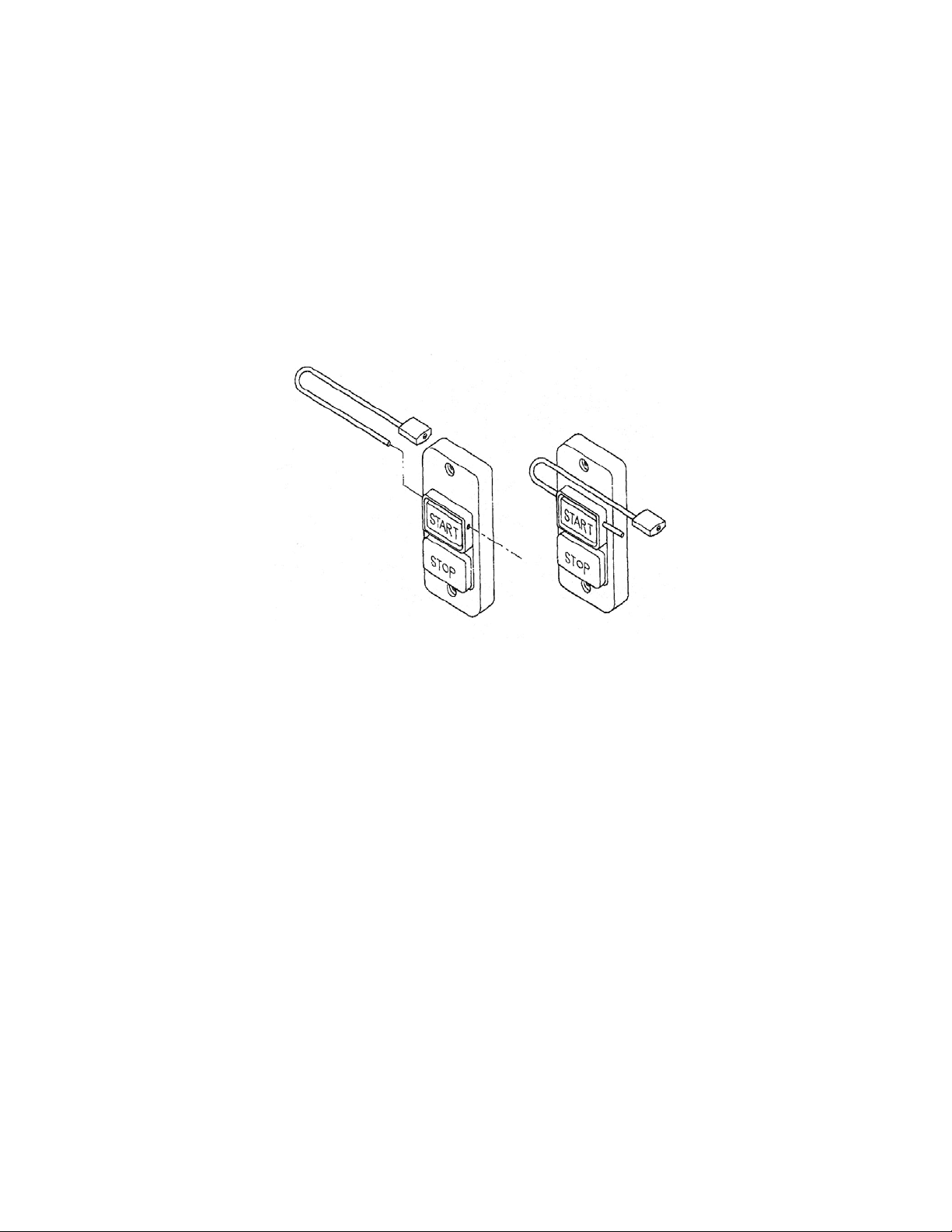
The Sander is equipped with a push-butt on switch that will accept a safety padlock (not included). To
safeguard your m achine from unauthor ized operation and acci dental starting by y oung children, t he use
of a padlock is highl y recommended.
To lock out the switch:
1. Open the padlock. S ee Figure 1.
2. Insert through holes in the start button.
3. Close the padlock .
4. Secure the key in a safe plac e.
Figure 1
7
Page 8
Grounding Instructions
Electri cal co nnect ions must b e made b y a quali fied el ectrici an in complian ce with
all relevant codes. This machine must be properl y grounded to help preven t electri cal shock and
possible fa t a l in jury.
In the event of a malfunction or breakdown, groundi ng provides a path of least resistance for electric
current to reduce the risk of electric shock. This tool is equipped with an electric cord having an
equipment-gr ounding conductor and a groundi ng plug. The pl ug must be plugged into a matc hing outlet
that is properly installed and grounded in accor danc e with all local codes and ordinances.
Do not modify the plug provided. If it will not fit the outl et, have the proper outl et installed by a qualif ied
electrician.
Improper connection of the equipment-grounding conductor can result in a risk of electric shock. The
conductor, with insulation having an outer surface that is green with or without yellow stripes, is the
equipment-gr ounding conduct or. If repai r or replacem ent of the electri c cord or plug i s necessary, do not
connect the equipment-grounding conductor to a live terminal.
Check with a qualified electrician or service personnel if the grounding instructions are not completely
understood, or if in doubt as to whether the tool is properly gr ounded. Use only three wire ex tension cords
that have thr ee- pr ong gr ounding plugs and three-pole receptac les that accept the tool’s plug.
Repair or replace a dam aged or worn cord im mediately.
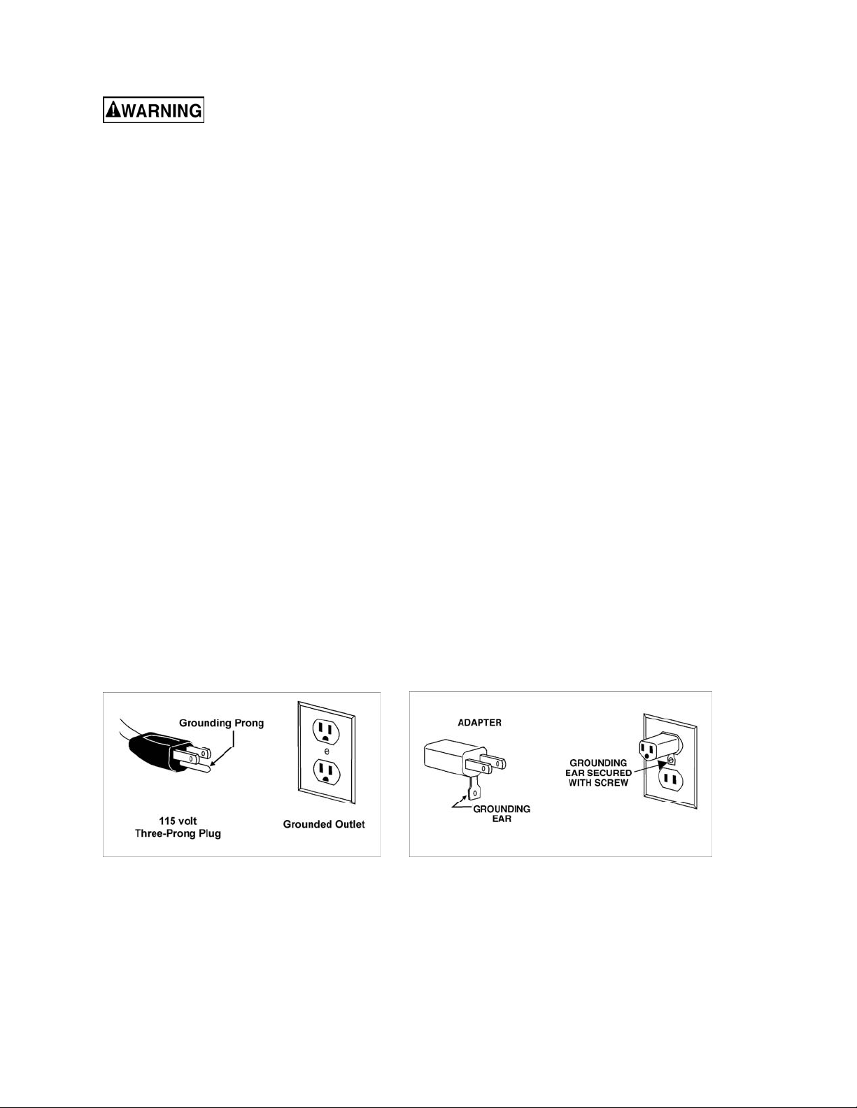
115 Volt Operation
As received fr om the factory, your sander is wired to run at 115 v olt operation. This sander when wired for
115 volts, is intended for use on a circuit that has an outlet and a plug that looks the one illustrated in
Figure 2. A temporar y adapter , which looks like the adapter illustrated in Figure 3, may be used to
connect this plug to a two-pole receptacle, as shown in Figure 3 if a properly grounded outlet is not
available. The temporary adapter should only be used until a properly grounded out let can be installed by
a qualified elec tr ic ian. This adapter is not applicable in Canada. The green colored rigid ear, lug, or
tab, extending from the adapter, must be connect ed to a permanent ground such as a properly grounded
outlet box, as shown in Fi gur e 3.
It is recommended t hat t he JSG - 6DC Belt/Disc Sander, when operated at 115 volt , be connec ted to a
grounded and dedicated, minimum 30 amp circuit wit h a 30 amp circuit breaker or time delay fuse. Local
codes take preceden ce over recommendations.
Figure 2 Figure 3
230 Volt Operation
If 230V, singl e- phase operat ion is desired, the followi ng instructions must be followed:
1. Disconnect the m ac hine from the power source.
2. This sander is supplied with four motor leads that are connected for 115V operation, as shown in
Figure 4. Remove the switch box, and reconnect t hese four motor leads for 230V operation, as shown
in Figure 5. Re-install the switch box.
8
Page 9
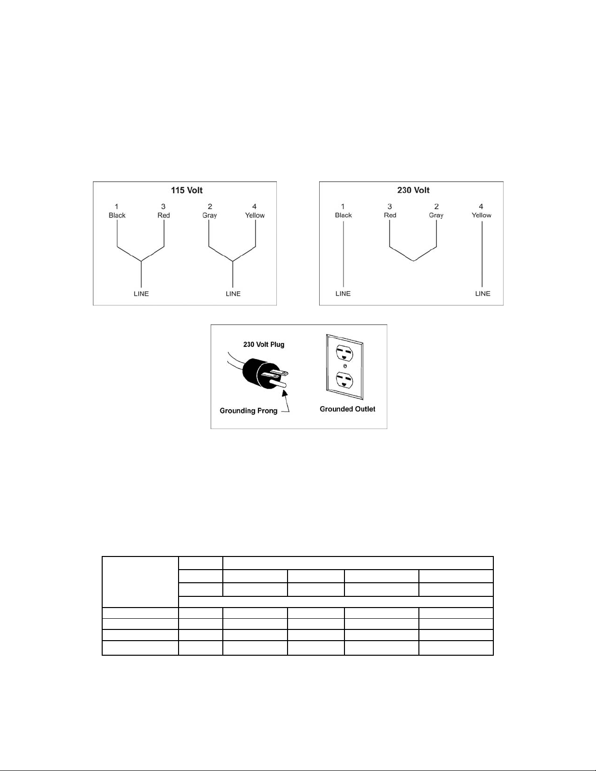
3. The 115V att achment plug (shown in F igure 6) suppli ed with the sander, must be replaced with a
A
UL/CSA listed plug suitable for 230V operation (shown in Figure 7). Contact your local authorized
JET servic e center or qual ified el ectri cian for proper procedures to instal l the pl ug. The sa nder must
comply with all l oc al and national codes after the 230 volt plug is installed.
4. The band saw with a 230 volt plug should only be connected to an outlet having the same
configuration (see Figure 7). No adapter i s available or should be used with the 230 volt plug.
Important: In all cases (115 or 230 volts), m ake certain the rec eptacle in quest ion is properl y grounded.
If you are not sure, have a regi ster ed electrician check the rec eptacle.
It is recom mended that the JSG -6DC Belt/Disc Sander, when operated at 230 vo lt, be connected to a
grounded and dedicat ed, minimum 15 am p circuit with a 15 amp cir cuit br eaker or tim e delay fuse. Local
codes take preceden ce over recommendations.
Figure 4 Figure 5
Figure 6
Extens ion Cords
If an ext ension cord is necessary, make sure the cord r ating is suitabl e for the amperage l isted on the
machine’s mot or plat e. An undersized c ord will cause a drop i n line v oltage r esulting in loss of power and
overheating.
Use the chart in Figure 7 as a general guide in cho osi ng the correc t size extension cord for the Sander. If
in doubt, use the next heav ier gauge. The smaller the gauge number, the heavier the cord.
Recommended Minimum Gauge (AWG) of Extension Cords
Volts Total Length of Cord in Feet
115 V 25 ft. 50 ft. 100 ft. 150 ft.
230 V 50 ft. 100 ft. 200 ft. 300 ft.
Ampere Rating
< 6 18 16 16 14
6 to 10 18 16 14 12
10 to 12 16 16 14 12
12 to 16 14 12 Not recommended Not recommended
Figure 7
WG
9
Page 10

Unpacking
Open shipping car ton(s) and check for shipping
damage. Report any damage immediately to
your distributor and shipping agent. Do not
discard any shi pping m at erial until t he Sander i s
assembled and running properly.
Compare the c ontents of your carton(s) with t he
following parts list to make sure all parts are
intact. Mi ssing parts, if any, should be repor ted
to your distr ibutor. Read the instructi on manual
thoroughly for assembly, maintenance and
safety instructions.
Contents of Main Carton
See Figure 8.
1 Belt/Di sc Sander (A)
1 Belt Sanding Table (B)
1 Disc Sanding Table (C)
1 Miter Gauge Assembly ( D)
1 Workstop Assembl y (E)
2 Lock Knobs (F)
1 Belt Tensioning Handle w/ Nut (G)
1 Table Lock Handle ( H)
1 12-inch Abrasive Disc (I)
1 6 x 48-inch Abrasive B elt (J )
1 Operator’s Manual ( not shown)
1 Warranty Car d (not shown)
1 Hardware Bag (K), containing:
1 Hex Key, 6mm
4 Hex Cap Screws, M10 x 80
9 Flat Washers, M10
4 Lock Washers, M10
4 Hex Nuts, M10
Figure 8
10
Page 11

Contents of Closed Stand Carton:
(Optional Accessory – p/ n 708598)
See Figure 9.
1 Stand
1 Owner’s Manual (not shown)
1 Hardware Bag*, cont aining:
4 Hex Cap Screws, M10 x 80
8 Flat Washers, M10
4 Lock Washers, M10
4 Hex Nuts, M10
(*Note: The c los ed s tand hardwar e bag contains
the same fasteners as the sander har dware bag,
and will not be needed if you purchas ed sander
and stand together .)
Figure 9
(Optional Accessory)
Contents of Open Stand Carton :
(Optional Accessory – p/ n 708566)
See Figure 10.
1 Top
4 Legs
4 Long Cross Braces
4 Short Cross Braces
1 Owner’s Manual (not shown)
1 Hardware Bag, cont aining:
40 Carriage Bolts, M8x16
40 Lock Washers, M8
40 Flat Washers, M8
40 Hex Nuts, M8
Figure 10
(Optional Accessory)
11
Page 12

Assembly
Tools required for assembly:
4mm Hex Key
6mm Hex Key (provided)
13mm open-end wrench
(2) 11/16” wrenches or sockets
Machine is heavy! Use
caution when lifting out of the shipping
carton and mo ving to a final location. S tand
or bench must be stable enough to support
heavy weight.
1. Use a hoist with straps to remove the
Sander from the cart on. Pr event str aps f rom
contacting any levers or switches while
lifting.
2. Carefully position the machine on a
workbench or one of the optional JET
stands. (Consult the assembly instructions
that accompanied the stand.)
3. Bolt the unit firmly to secure it in position.
Figure 11 shows it being bolted to the
optional cl osed stand. Use the four M10x80
hex cap screws, with M10 l ock washers, flat
washers and hex nuts. Tighten hex nut
while holding the screw head stationary,
using two 11/16” wrenches. Remove lifting
straps.
Figure 11
(closed stand optional)
4. Ex posed metal surfaces have been f actory-
coated with a prot ectant. Remove this using
a soft cloth and a solvent or cleaner/
degreaser. (Not e: Keep solvents away from
painted surfaces and plastic parts, and do
not use an abrasiv e pad, as it may scratch
the polished metal surfaces.)
Machine should be dis-
connected from power during all assembly
procedures.
Disc Table
1. Rem ove the left and right trunnion br ackets
(A, Figure12) from the trunnion holder (B).
2. Make sure the stop block ( shown in Figure
23) is flipped out of the way.
3. Place the disc table on top of the trunnion
assemblies and position each trunnion
bracket (A) so that it sli ps onto the threaded
stud and two pi ns of t he trunni on hol der (B ),
while engaging t he lip of t he table trunnion
(C).
Figure 12
Figure 13
12
Page 13

Note: The trunnion brackets are not
identical; make sure the bracket with the
raised indicator line is installed on the left
side of the table.
4. Install a lock knob (D) on each threaded
stud and tighten to hold the table in position.
5. See “Adjustments” section for further
instruction on adjusting the disc table.
Belt Table
1. Loosen the sanding platen lock screw (E,
Figure 13) wit h a 6mm hex wrench, and ti lt
the belt arm to a vertical posi tion. Re-ti ghten
the lock screw.
2. Guide the belt table trunnion ont o the stud,
as shown in Figur e 14. The raised track on
the trunnion m ust fit into the gr oove on the
belt arm.
3. Place the remaining M10 flat washer onto
the stud (Figure 15).
4. Thread the nut of the table lock handle
(Figure 15) onto the stud. T o do this quick ly,
pull out on the handle, while tightening the
nut with a 4mm hex wrench. When the nut is
fully tightened onto the stud, release the
handle, making sure it seats itself back ont o
the nut.
Note: The table lock handle can be
repositioned at any time for convenience by
pulling out on t he handle, rot ating it to new
position, then releasing it. Make sure it reseats itself on t he nut.
5. Screw the bel t tensioning handle (Figure 16)
into the threaded hole in the belt tracking
assembly, and tighten the hex nut against
the shaft with a 13mm wrench.
Figure 14
Figure 15
6. See “Adjustments” section for further
instruction on adjusting the belt table.
Installing Abrasives
Abrasive Disc
Note: You may wish to c heck the angle setting
of the table before installing the abrasive disc.
See “Disc Table Adjustm ent”.
To install the abr asive disc:
1. Disconnect machine from power source.
2. Make sure the aluminum disc is clean and
dry.
3. Peel the backing from the abrasive and
carefully insert it between disc and table;
align and press int o plac e.
Figure 16
13
Page 14

4. Rotat e disc a half turn and pr ess other half
of abrasive into plac e. Make sure to remove
any entrapped air by pressing all parts of
the abrasive against the disc.
Abrasive Belt
1. Disconnect machine from power source.
2. Raise the belt arm to vertic al posi tion.
3. Loosen lock screw and open lef t side panel.
4. Most brands of replacement abrasives are
directional, and must be installed in the
proper direction. Directional belts are so
indicated on t he backi ng m ateri al by arrows.
The direction of the abrasive should match
that of the arrow on the platen assembly
(Figure 17).
NOTE: Failure to comply wi th abrasive belt
directional instructions may result in
prematur e belt break age.
5. Once the belt direction has been
determined, pull the belt tensioning handle
toward you with one hand, while using the
other hand to sli de the belt ont o both drums
and over the platen pad. S ee Figure 17.
6. Center the belt on the platen and release
the belt tensioning handle.
7. Before operating, the belt shoul d be tracked.
See “Belt Tracking A djustment.”
Workstop Assembly
Figure 17
When the sanding belt is to be used in the
horizontal position, the tabl e may be used as a
fence; or the table may be removed and the
workstop assembl y installed.
Refer to Figure 18.
1. Remove table and trunnion assembly by
removing the table lock handle and washer.
2. Slide workstop brac ket onto stud an d fasten
with the washer and lock handle.
3. Adjust workstop t o clear bel t before st arting
machine.
Figure 18
14
Page 15

Dust Collection
It is strongly recomm ended that a dust collection
system (not included) be connected to the
sander. Mount a 4-inch hose to the sander’s
dust port and secure with a hose clamp. (N ote:
Dryer vent hose is not sui table for such use).
The dust collector should have sufficient
capacity for thi s size machi ne; a minimum rating
of 450 CFM (cubic feet per minute) is
recommended.
A variety of JET dust coll ectors i s available; see
our website at www.jettools.com.
Adjustments
Tools required for adjustments:
3mm hex key
6mm hex key (provi ded)
10mm wrench
13mm wrench
Combinati on and/or m ac hinist’s square
Cross-point Sc r ewdriver
Figure 19
Belt Table Adjustment
1. Disconnect machine from the power source.
2. Place a square on t he table and up against
the platen or abrasive belt, as shown in
Figure 19.
3. Loosen t he table lock handle and move the
table until the square sits flush to both
surfaces at 90°. Ti ghten the lock handle.
4. Place a combination square in the miter
gauge slot and check t he distance from the
slot to the f ace of the pl aten. See Fi gure 20.
Slide the squar e along the slot to the other
side of the platen and check the distance.
The distances should be equal to ensure
that the miter gauge travels parallel to the
belt.
5. If the t abl e i s not paral lel, loosen the scre ws
below the table ( A, Figure 21) with a 13m m
wrench, and nudge the table until parallel.
Re-tighten scr ews.
Note: Always maintain a gap of
approxim ately 1/16” between the t able edge
and the abrasive belt.
Once the tabl e is square and paral l el to the belt,
verify the stops, as follows:
Figure 20
Figure 21
15
Page 16

Adjust 90° Stop
6. With t he table loc ked at 90°, loosen the hex
nut on the 90° stop, and adjust the set
screw to seat against the stop block. See
Figure 19. Re-tighten hex nut to secure the
setting.
7. If angle indicator adjustment is necessary,
loosen the screw and shift the pointer to
zero, and re-ti ghten the screw.
Adjust 45° Stop
8. Flip the stop block out of the way, and tilt
the table down to 45°. Verify the setting of
the 45° angle stop (Figure 19). Use the
same procedure as above but with a 45°
measuring device on the table. Correct the
stop as needed.
Belt Arm Orientation
Loosen the belt ar m lock screw (see Fi gure 13)
to tilt the belt arm to vertical or horizontal
position. The belt arm can also be secured at
any angle between. Always tighten the screw
before operating.
Note: Belt tracki ng may require r e-adjustment if
the belt assembly is moved from vertical to
horizontal or bac k agai n.
Figure 22
Limit Screw Adjus tment
This set screw (Fi gure 22) limits the rotation of
the belt arm to vertical and horizontal positions,
and has been pre-set. If it shoul d ever need readjustment:
1. Loosen lock nut on the set screw with a
10mm wrench.
2. W ith a 3mm hex key, turn set screw al l the
way in until it bottoms out. Back screw out
three turns and re-tighten lock nut, while
holding screw in place.
Disc Table Adjustment
1. Disconnect machine from power source.
2. Place a square on t he table and agai nst the
disc. See Figure 23. Loosen both lock
knobs, move the table until the square sits
flush to both surf aces at 90°, and re- tighten
both knobs. Note: You may need to pivot
the stop block out of the way.
3. Place a combination square in the miter
gauge slot and check t he distance from the
slot to face of the disc. S ee Figure 24. Sli de
the square along the slot to the other side of
the disc and check the distance. The
distances should be equal to ensure that the
miter gauge trav els parallel to the disc.
Figure 23
Figure 24
16
Page 17

4. If table is not parallel, loosen the four
screws holding t he tabl e t o the t runni ons (B,
Figure 25) wit h a 12mm wrench, and nudge
the table until parallel. Re-tighten scr ews.
Note: Always maintain a gap of
approxim ately 1/16” between the t able edge
and the abrasive disc.
Once the table is square and paral lel to t he disc,
verify the stops, as follows:
Adjust 90° Stop
5. Loosen lock nut on t he 90° stop ( Figure 23)
with a 10mm wrench. Turn the set screw
down (3mm hex key) to contact the table.
Re-tighten lock nut.
Adjust 45° Stop
6. To adjust the 45° stop, pivot the 90° stop
block out of the way, and t il t the tabl e down
against the 45° stop screw (Figure 25).
Check the angle with a 45° measuring
device on the table and against the disc.
7. If adjustment is necessary, loosen the hex
nut, turn t he stop screw as needed, and retighten the hex nut t o secure the setting.
Figure 25
Figure 26
Adjust Rear Stop
The rear stop (Figur e 26) is used when tilting the
disc table upward. It can be set to limit the table
tilt t o about mi nus 15°. T o ti lt t he tabl e t o the f ull
minus 25°, remov e the r ear stop scre w and nut.
Miter Gauge
Refer to Figure 27.
Check the zero setting of the miter gauge.
(Note: Make sure t he mi ter slot i s parallel to the
disc surface.)
1. Place the mi ter gauge into t he disc table slot
and loosen the miter gauge k nob.
2. Place a square against miter gauge and
disc so that it sits flush against both
surfaces.
3. Tighten the knob, and check the zero
setting. If necessary, adjust the pointer to
the zero mark.
Figure 27
17
Page 18

Belt Tracking Adjustment
The belt shoul d run at t he c enter of the bel t arm
without v eering to the left or right . Check this as
follows:
1. Disconnect machine from the power source.
2. Rotate the bel t by hand and ob serve how it
tracks. The belt should run centered on the
belt wheels.
3. If the belt has a tendency to track left or
right of center, loosen locking nuts (A,
Figure 28).
4. Turn the front screw (B, Figure 28) while
turning the belt by hand and observe belt
tracking. Once the belt starts to move in the
desired direction, stop and turn the rear
screw (C) in the same manner. NOTE:
These adjustment s are s ensitiv e and s hould
be done in small increments .
5. Grasp the tensioni ng adjustment handl e (D)
and start the machine. Be ready to pull
down on the tension adjustment handle
should the belt want to run off the belt
wheel.
Figure 28
6. Fine adjustment of the tracking may be
necessary. When the tracking has
stabilized, slowly rel ease the belt tensioni ng
arm and let the machine run for two
minutes.
7. Tighten lock nuts (A) when tracking
adjustments are satisfactory.
Belt Replacement
1. Disconnect machine from the power source.
2. Remove the lock knob and open the left
side panel.
3. Release belt tension using the handle (D,
Figure 28), and slide belt off the wheels.
4. Refer to “Installing Abrasives” section for
instructions on installing the new belt.
Abrasive Disc Replacement
1. Disconnect machine from the power source.
2. Slowly work the tip of a knife under the
abrasive disc, and work it around the
circumferenc e of the di sc until abrasiv e can
be removed by hand.
3. Clean the aluminum disc of any residual
adhesive, using mineral spirits or similar
solvent. Allow to dry .
4. See “I nstal l ing A brasives” f or i nstructi ons on
installi ng the new abrasive disc.
Maintenance
Before doing maintenance on
the machine, disco nnect it from the electri cal
supply by pulling out the plug or switching
off the main switch! Failure to comply may
cause serious inj ury.
Wipe the machine down af ter each use.
Keep exposed metal surfaces clean and rust-
free. A light coat of paste wax applied to the
tables will help protect the surfaces.
Make periodic inspections of the sander,
checking fastener tightness, abrasive wear,
tracking accuracy, etc. Listen for any unusual
motor noises or vibrations that might indicate
bearing fatigue.
(Note: All rotating parts run on sealed ball
bearings and do not requi r e lubr ication.)
If you will not be using the machine for an
extended period, remove the abrasive belt; this
will prev ent it from stretching and will prolong it s
life.
If the power cord is worn, cut, or damaged in any
way, have it replaced immediately.
18
Page 19

Troubleshooting
Trouble Probable Cause Remedy
Sander will not star t.
Sanding belt does not
come up to speed.
Sander vibrates
excessively.
Abrasive belt keeps
tearing.
Sanded edge not
square.
Sander unplugged from wall, or
motor.
Fuse blown or circuit breaker tripped.
Cord damaged. Replace cord.
Starting capac itor bad. Replace starting capacitor.
Extension cord too light or too long.
Low current. Contact a qualified electrician.
Stand on uneven surf ac e.
Bearing fatigue.
Motor probl em.
Belt running in wrong di r ec tion.
Table not square to abrasive belt.
Miter slot not parallel to abrasive belt.
Check all plug connections.
Replace fuse, or r eset ci r c uit br eak er .
Verify that supply ci r c uit is appropriate
for amperage rati ng on m otor plate.
Replace with adequat e si z e and
length cord.
Adjust stand so that it r ests evenly on
the floor.
Have bearings replac ed by a qualified
service technician.
Have motor inspected by a qualified
technician.
Arrows on abrasive belt and machine
should be pointing same direction.
Use a square to adjust table to
abrasive belt.
Use a square to adjust table’s miter
slot parallel to abrasive belt.
Work held still. Keep workpiece m ov ing.
Sanding marks on
wood.
Wrong grit sanding belt.
Feed pressure too great . Never force work i nto sanding platen.
Sanding against the grain. Sand with the grain.
Use coarser grit for stoc k removal and
fine grit for finish sanding.
Optional Accessories
708566 ........ JSG-6SA, Open S tand
708598 ........ JSG-6DC-CS, Closed Stand
Dust Collectors and Accessories.....see your JET distributor
Replacement Parts
Replacement par ts are li sted on the f ollowing page s. To order parts or reac h our servi ce depar tm ent, call
1-800-274-6848, Mon day t hrough Fr iday (see our web sit e f or busi ness hours, www.j ett ool s.com). Havi ng
the Model Num ber and S eri al Num ber of y our machi ne avail abl e when you cal l will allow us to serve you
quickly and acc ur ately.
19
Page 20

JSG-6DC Belt/Disc Sander Assembly
20
Page 21

Parts List for JSG-6DC Belt/Disc Sander Assembly
Index No. Part No. Description Size Qty
1 ................ 612001W ................... Base.................................................................. ............................................. 1
2 ................ 612002W ................... Base Plate ........................................................ ............................................. 1
3 ................ SF069300.................. Pan Head Screw (w/flange) .............................. M6x12 .................................. 6
4 ................ 612003W ................... Front Plate ........................................................ ............................................. 1
5 ................ SF069300.................. Pan Head Screw (w/flange) .............................. M6x12 .................................. 4
6 ................ 612004W ................... Dust Tube ......................................................... ............................................. 2
7 ................ 612005 ...................... Gasket .............................................................. ............................................. 2
8 ................ SF069300.................. Pan Head Screw (w/flange) .............................. M6x12 .................................. 8
9 ................ 612006W ................... Dust Hood ......................................................... ............................................. 1
10 .............. MA150001W ............. Motor................................................................. ............................................. 1
.................. 990019 ...................... Centrifugal Switch ............................................. ............................................. 1
.................. 991500 ...................... Start Capacitor .................................................. 500MFD, 125VAC................ 1
.................. 991050 ...................... Run Capacitor ................................................... 50MFD, 250VAC.................. 1
11 .............. CC324101 ................. Power Cord ....................................................... ............................................. 1
12 .............. 150508 ...................... Strain Relief Plate ............................................. ............................................. 1
13 .............. 998623 ...................... Strain Relief ...................................................... ............................................. 1
14 .............. SF059100.................. Pan Head Screw (w/flange) .............................. M5x6 .................................... 2
15 .............. 612007 ...................... Switch Box ........................................................ ............................................. 1
16 .............. 994503 ...................... Switch ............................................................... ............................................. 1
17 .............. ST040400.................. Tapping Screw .................................................. M4x20 .................................. 2
18 .............. 612008 ...................... Pad ................................................................... ............................................. 1
19 .............. SF059100.................. Pan Head Screw (w/flange) .............................. M5x12 .................................. 2
20 .............. SR080700 ................. Hex Socket Cap Screw ..................................... M8x35 .................................. 4
21 .............. 612009W ................... Bracket.............................................................. ............................................. 1
22 .............. SR080700 ................. Hex Socket Cap Screw ..................................... M8x35 .................................. 1
23 .............. NH061000 ................. Nut .................................................................... M6 ........................................ 1
24 .............. SS060600 ................. Set Screw ......................................................... M6x30 .................................. 1
25 .............. 610010 ...................... Stop Block......................................................... ............................................. 1
26 .............. PS054500 ................. Spring Pin ......................................................... 5x45 mm .............................. 1
27 .............. 612011 ...................... Scale ................................................................. ............................................. 1
28 .............. VS020500 ................. Rivet.................................................................. M2x5 .................................... 3
29 .............. KD050560 ................. Key.................................................................... 5x 5x60 mm .......................... 1
30 .............. 612012 ...................... Drive Roller ....................................................... ............................................. 1
31 .............. 612013 ...................... Flange ............................................................... ............................................. 1
32 .............. NH243600 ................. Nut .................................................................... M24 ...................................... 1
33 .............. 612014 ...................... Eccentric Shaft Bracket .................................... ............................................. 1
34 .............. 612015 ...................... Spring Plate ...................................................... ............................................. 3
35 .............. SR109400 ................. Hex Socket Cap Screw ..................................... M10x16 ................................ 6
36 .............. 612016 ...................... Nut .................................................................... ............................................. 2
37 .............. 612017 ...................... Adjusting Screw ................................................ ............................................. 2
38 .............. SR069200 ................. Hex Socket Cap Screw ..................................... M6x8 .................................... 1
39 .............. 612018 ...................... Eccentric Shaft.................................................. ............................................. 1
40 .............. RS200000 ................. Retainin g Ring .................................................. S20 ...................................... 1
41 .............. 612019 ...................... Spring ............................................................... ............................................. 1
42 .............. 612020 ...................... Eccentric Shaft Bushing.................................... ............................................. 1
43 .............. 612021 ...................... Locating Block .................................................. ............................................. 1
44 .............. SM0606400 ............... Countersunk Head Bolt..................................... M6x20 .................................. 1
45 .............. 612022 ...................... Follow Roller ..................................................... ............................................. 1
46 .............. BB-6202LLU.............. Ball Bearing ...................................................... 6202LLU .............................. 2
47 .............. RS150000 ................. Retainin g Ring .................................................. ............................................. 1
48 .............. 612023W ................... Sanding Platen ................................................. ............................................. 1
49 .............. 612024 ...................... Sanding Belt Pad .............................................. ............................................. 1
50 .............. .................................. Sanding Belt (local purchase) ........................... ............................................. 1
51 .............. SR100700 ................. Hex Socket Cap Screw ..................................... M10x35 ................................ 2
52 .............. WF102830................. Flat Washer ...................................................... M10 ...................................... 1
53 .............. 612026W ................... Sanding Belt Guard .......................................... ............................................. 1
54 .............. 612027W ................... Outlet Guard ..................................................... ............................................. 1
55 .............. 612028 ...................... Hinge ................................................................ ............................................. 1
56 .............. TS049200.................. Tapping Screw .................................................. M4x8 .................................... 8
57 .............. 612029W ................... Access Door ..................................................... ............................................. 1
21
Page 22

Index No. Part No. Description Size Qty
58 .............. 612030 ...................... Hinge ................................................................ ............................................. 2
59 .............. ST049200.................. Tapping Screw .................................................. M4x8 .................................... 8
60 .............. 612031 ...................... Lock Knob ......................................................... ............................................. 1
61 .............. SF069300.................. Pan Head Screw (w/flange) .............................. M6x12 .................................. 6
62 .............. KD050525 ................. Key.................................................................... 5x 5x25 mm .......................... 1
63 .............. 612032W ................... Disc Guard ........................................................ ............................................. 1
65 .............. SP080400 ................. Pan Head Screw ............................................... M8x20 .................................. 4
66 .............. 612033 ...................... Sanding Disc..................................................... ............................................. 1
67 .............. .................................. Disc Abrasive (local purchase) ......................... ............................................. 1
68 .............. SS060200 ................. Set Screw ......................................................... M6x10 .................................. 2
69 .............. 612035 ...................... Table Bracket.................................................... ............................................. 1
70 .............. 612010 ...................... Stop Block......................................................... ............................................. 1
71 .............. NH061000 ................. Nut .................................................................... M6 ........................................ 1
72 .............. SS060500 ................. Set Screw ......................................................... M6x25 .................................. 1
73 .............. PS052500 ................. Spring Pin ......................................................... 5x25 mm .............................. 1
74 .............. 150031 ...................... Pin..................................................................... ............................................. 1
75 .............. SH080500 ................. Hex Cap Bolt..................................................... M8x25 .................................. 1
76 .............. WF081818................. Flat Washer ...................................................... M8 ........................................ 1
77 .............. WS080000 ................ Lock Washer ..................................................... M8 ........................................ 1
78 .............. 612037 ...................... Table Bracket.................................................... ............................................. 1
79 .............. SH080800 ................. Hex Cap Bolt..................................................... M8x40 .................................. 2
80 .............. PS063000 ................. Spring Pin ......................................................... 6x30 mm .............................. 4
81 .............. 150031 ...................... Pin..................................................................... ............................................. 2
82 .............. SH089400 ................. Hex Cap Bolt..................................................... M8x16 .................................. 4
83 .............. WF081818................. Flat Washer ...................................................... M8 ........................................ 4
84 .............. WS080000 ................ Lock Washer ..................................................... M8x ...................................... 4
85 .............. 612038 ...................... Trunnion Bracket .............................................. ............................................. 1
86 .............. 990551 ...................... Knob ................................................................. ............................................. 2
87 .............. 612039W ................... Sanding Table................................................... ............................................. 1
88 .............. 612040W ................... Trunnion............................................................ ............................................. 1
89 .............. 612041 ...................... Sliding Plate ...................................................... ............................................. 1
90 .............. PS040800 ................. Spring Pin ......................................................... 4x12 mm .............................. 2
91 .............. 612056 ...................... Pointer .............................................................. ............................................. 1
92 .............. SF059100.................. Pan Head Screw (w/flange) .............................. M5x6 .................................... 1
93 .............. SH080400 ................. Hex Cap Bolt..................................................... M8x20 .................................. 3
94 .............. WF081818................. Flat Washer ...................................................... M8 ........................................ 3
95 .............. WS080000 ................ Lock Washer ..................................................... M8 ........................................ 3
.................. AA612042 ................. Workstop Assembly CP .................................... ............................................. 1
96 .............. 612042W ................... Fence ................................................................ ......... .................................... 1
97 .............. 612043W ................... Support Arm...................................................... ............................................. 1
98 .............. 612044 ...................... Stud .................................................................. ............................................. 1
99 .............. WF102825................. Flat Washer ...................................................... M10 ...................................... 1
100 ............ 612045W ................... Table ................................................................. ............................................. 1
101 ............ 612046 ...................... Trunnion............................................................ ............................................. 2
102 ............ SH089400 ................. Hex Cap Bolt..................................................... M8x16 .................................. 4
103 ............ WS080000 ................ Lock Washer ..................................................... M8 ........................................ 4
.................. AA150401 ................. Miter Gauger Assembly CP .............................. ............................................. 1
104 ............ 150401 ...................... Guide Bar.......................................................... ............................................. 1
105 ............ 199083 ...................... Gauge Body ...................................................... ............................................. 1
106 ............ PS051200 ................. Spring Pin ......................................................... 5x12 mm .............................. 1
107 ............ 612036 ...................... Knob ................................................................. ............................................. 1
108 ............ 150406 ...................... Gasket .............................................................. ............................................. 1
109 ............ 150402 ...................... Pointer .............................................................. ............................................. 1
110 ............ SP550200 ................. Pan Head Screw ............................................... 3/16” x 1/4" .......................... 1
111 ............ 612047 ...................... Lock Knob Assembly ........................................ ............................................. 1
112 ............ 612048 ...................... Handle .............................................................. ............................................. 1
113 ............ NH081300 ................. Nut .................................................................... M8 ........................................ 1
114 ............ TS-1527071 .............. Hex Wrench ...................................................... 6mm ..................................... 1
115 ............ NH101700 ................. Nut * .................................................................. M10 ...................................... 4
116 ............ SH101600 ................. Hex Cap Bolt * .................................................. M10x80 ................................ 4
117 ............ WF102825................. Flat Washer ...................................................... M10 ...................................... 9
118 ............ WS100000 ................ Lock Washer * .................................................. M10 ...................................... 4
22
Page 23

Index No. Part No. Description Size Qty
119 ............ 612052 ...................... Trunnion Holder ................................................ ............................................. 1
120 ............ 612053 ...................... Stud .................................................................. ............................................. 1
121 ............ 612054 ...................... Table Bracket.................................................... ............................................. 1
122 ............ NH081300 ................. Nut .................................................................... M8 ........................................ 1
123 ............ SR080500 ................. Hex Socket Cap Screw ..................................... M8x25 .................................. 1
124 ............ WS060000 ................ Lock Washer ..................................................... M6 ........................................ 1
125 ............ WS080000 ................ Lock Washer ..................................................... M8 ........................................ 4
126 ............ NH061000 ................. Nut .................................................................... M6 ........................................ 2
127 ............ SS060600 ................. Set Screw ......................................................... M6x30 .................................. 2
* Items included in AH612J1 Hardware Kit
23
Page 24

Closed Stand Assembly (Optional)
Index No. Part No. Description Size Qty
.................. 708598 ...................... Closed Stand Assembly Complete ................... ............................................. 1
1 ................ AB612062 ................. Closed Stand .................................................... ............................................. 1
2 ................ TS-0060111 .............. Hex Cap Screw ................................................. 3/8” x 2-1/2” ......................... 4
3 ................ TS-1550071 .............. Flat Washer ...................................................... M10 x 20 .............................. 9
4 ................ 150105 ...................... Wheel................................................................ ............................................. 4
5 ................ TS-0640091 .............. Nyloc Lock Nut.................................................. 3/8”............. .......................... 5
6 ................ 150103 ...................... Stop .................................................................. ............................................. 2
7 ................ TS-1523031 .............. Set Screw ......................................................... M6 x 10 ................................ 2
8 ................ 612063 ...................... Stop Shaft ......................................................... ............................................. 1
9 ................ PS042400 ................. Spring Pin ......................................................... 4 x 24 mm ............................ 1
10 .............. 150106 ...................... Spring ............................................................... ............................................. 1
11 .............. 150104 ...................... Step Plate ......................................................... ............................................. 1
12 .............. 145002 ...................... Door .................................................................. ............................................. 1
13 .............. 150503 ...................... Lock .................................................................. ............................................. 1
14 .............. 150527 ...................... Pad ................................................................... ............................................. 2
Hardware used to attach the Sander to the Closed Stand
.................. AH612J1 ................... Hardware Bag (contains the items below) ........ ............................................. 1
.................. TS-229801 ................ Hex Cap Screw (not shown) ............................. M10 x 1.5 x 80 ..................... 4
.................. TS-1550071 .............. Flat Washer (not shown)................................... M10 ...................................... 8
.................. TS-1551071 .............. Lock Washer (not shown) ................................. M10 ...................................... 4
.................. TS-1540077 .............. Hex Nut (not shown) ......................................... M10 x 1.5 ............................. 4
24
Page 25

Open Stand Assembly (Optional)
Parts List for Open Stand Assembly (Optional)
Index No. Part No. Description Size Qty
.................. 708566 ...................... Open Stand Assembly Complete...................... ............................................. 1
A ................ 612049 ...................... Stand Top (blue) ............................................... ............................................. 1
.................. 612049W ................... Stand Top (white) ............................................. ............................................. 1
B ................ 150603 ...................... Stand Leg (blue) ............................................... ............................................. 4
.................. 150603W ................... Stand Leg (white).............................................. ............................................. 4
C ................ SC089400 ................. Carriage Bolt * .................................................. M8 x 16 .............................. 40
D ................ WF081818................. Flat Washer * .................................................... M8 ...................................... 40
E ................ WS080000 ................ Lock Washer * .................................................. M8 ...................................... 40
F ................ NH081300 ................. Hex Nut * .......................................................... M8 ...................................... 40
G ............... 612051 ...................... Cross Brace – short (blue) ................................ ............................................. 2
.................. 612501W ................... Cross Brace – short (white) .............................. ............................................. 2
H ................ 612050 ...................... Cross Brace – long (blue) ................................. ............................................. 2
.................. 612050W ................... Cross Brace – long (white) ............................... ............................................. 2
.................. AB612101 ................. Hardware Bag (includes items marked with *) .. ............................................. 1
25
Page 26

Electrical Connections
26
Page 27

27
Page 28

427 New Sanford Road
LaVergne, Tennessee 37086
Phone: 800-274-6848
www.jettools.com
28
 Loading...