

Page 1
This .pdf document is bookmarked
Operating Instructions and Parts Manual
12-inch XACTA® Cabinet Saw
Model JTAS-12-DX
JET
427 New Sanford Road
LaVergne, Tennessee 37086 Part No. M-708546
Ph.: 800-274-6848 Revision A1 02/2014
www.jettool s.c om Copyright © 2014 JET
Page 2

1.0 Warranty and Service
JET warrants every product it sells against manufacturers’ defects. If one of our tools needs service or repair, please
contact Technical Service by calling 1-800-274-6846, 8AM to 5PM CST, Monday through Friday.
Warranty Period
The general warranty lasts for the time period specified in the literature included with your product or on the official
JET branded website.
• JET products carry a limited warranty which varies in duration based upon the product. (See chart below)
• Accessories carry a limited warranty of one year from the date of receipt.
• Consumable items are defined as expendable parts or accessories expected to become inoperable within a
reasonable amount of use and are covered by a 90 day limited warranty against manufacturer’s defects.
Who is Covered
This warranty covers only the initial purchaser of the product from the date of delivery.
What is Co vered
This warranty covers any defects in workmanship or materials subject to the limitations stated below. This warranty
does not cover failures due directly or indirectly to misuse, abuse, negligence or accidents, normal wear-and-tear,
improper repair, alterations or lack of maintenance.
Warranty Limitations
Woodworking products with a Five Year Warranty that are used for commercial or industrial purposes default to a
Two Year Warranty. Please contact Technical Service at 1-800-274-6846 for further clarification.
How to Get Technical Support
Please contact Technical Service by calling 1-800-274-6846. Please note that you will be asked to provide proof
of initia l p u rch a s e whe n calling. If a product requires further inspection, the Technical Service representative will
explain and assist with any additional action needed. JET has Authorized Service Centers located throughout the
United States. For the name of an Authorized Service Center in your area call 1-800-274-6846 or use the Service
Center Locator on the JET website.
More Informa tion
JET is constantly adding new products. For complete, up-to-date product information, check with your local distributor
or visit the JET website.
How S tate Law Applies
This warranty gives you specific legal rights, subject to applicable state law.
Limitations on This Warranty
JET LIMITS ALL IMPLIED WARRANTIES TO THE PERIOD OF THE LIMITED WARRANTY FOR EACH PRODUCT.
EXCEPT AS STATED HEREIN, ANY IMPLIED WARRANTIES OF MERCHANTABILITY AND FITNESS FOR A
PARTICULAR PURPOSE ARE EXCLUDED. SOME STATES DO NOT ALLOW LIMITATIONS ON HOW LONG AN
IMPLIED WARRANTY LASTS, SO THE ABOVE LIMITATION MAY NOT APPLY TO YOU.
JET SHALL IN NO EVENT BE LIABLE FOR DEATH, INJURIES TO PERSONS OR PROPERTY, OR FOR
INCIDENTAL, CONTINGENT, SPECIAL, OR CONSEQUENTIAL DAMAGES ARISING FROM THE USE OF OUR
PRODUCTS. SOME STATES DO NOT ALLOW THE EXCLUSION OR LIMITATION OF INCIDENTAL OR
CONSEQUENTIAL DAMAGES, SO THE ABOVE LIMITATION OR EXCLUSION MAY NOT APPLY TO YOU.
JET sells through distributors only. The specifications listed in JET printed materials and on official JET website are
given as general information and are not binding. JET reserves the right to effect at any time, without prior notice,
those alterations to parts, fittings, and accessory equipment which they may deem necessary for any reason
whatsoever. JET
Product Listing with Warranty Period
90 Days – Parts; Consumable items; Light-Duty Air Tools
1 Year – Motors; Machine Accessories; Heavy-Duty Air Tools; Pro-Duty Air Tools
2 Year – Metalworking Machinery; Electric Hoists, Electric Hoist Accessories; Woodworking Machinery used
for industrial or commercial purposes
5 Year – Woodworking Machinery
Limited Lifetime – JET Parallel clamps; VOLT Series Electric Hoists; Manual Hoists; Manual Hoist
Accessories; Shop Tools; Warehouse & Dock products; Hand Tools
NOTE: JET is a division of JPW Industries, Inc. References in this document to JET also apply to JPW Industries,
Inc., or any of its successors in interest to the JET brand.
®
branded products are not sold in Canada by JPW Industries, Inc.
2
Page 3

2.0 Table of contents
Section Page
1.0 Warranty and Service ..................................................................................................................................... 2
2.0 Table of contents ............................................................................................................................................ 3
3.0 Safety warnings .............................................................................................................................................. 4
4.0 About this manual .......................................................................................................................................... 5
5.0 Glossary ......................................................................................................................................................... 6
6.0 Specifications ................................................................................................................................................. 7
7.0 Setup and assembly ....................................................................................................................................... 9
7.1 Tools required for assembly ....................................................................................................................... 9
7.2 Shipping contents ....................................................................................................................................... 9
7.3 Unpacking and cleanup ............................................................................................................................ 10
7.4 Installation and leveling ............................................................................................................................ 10
7.5 Installing table extensions ........................................................................................................................ 10
7.6 Installing motor cover ............................................................................................................................... 11
7.7 Installing handwheel ................................................................................................................................. 11
7.8 Installing storage hooks ............................................................................................................................ 11
7.9 Installing blade (not provided) .................................................................................................................. 11
7.10 Installing riving knife ............................................................................................................................... 12
7.11 Table insert adjustment .......................................................................................................................... 12
7.12 Installing anti-kickback pawls and blade guard assembly ...................................................................... 13
7.13 Installing rails and rip fence .................................................................................................................... 13
7.14 Installing switch and brace ..................................................................................................................... 13
7.15 Miter gauge operation ............................................................................................................................ 13
8.0 Electrical connections .................................................................................................................................. 14
8.1 Extension cords ........................................................................................................................................ 14
9.0 Adjustments ................................................................................................................................................. 14
9.1 Blade raising and tilting ............................................................................................................................ 14
9.2 Blade alignment ........................................................................................................................................ 14
9.3 Adjusting 90° and 45° positive stops ........................................................................................................ 15
9.4 Belt tension and replacement ................................................................................................................... 16
10.0 Maintenance ............................................................................................................................................... 16
11.0 Troubleshooting the JTAS-12-DX Table Saw ............................................................................................ 17
11.1 Mechanical Problems ............................................................................................................................. 17
11.2 Operational Problems ............................................................................................................................. 18
12.0 Replacement Parts ..................................................................................................................................... 18
12.1.1 Table and Cabinet Assembly (JTAS-12-DX) – Exploded View ........................................................... 19
12.1.2 Table and Cabinet Assembly (JTAS-12-DX) – Parts List .................................................................... 20
12.2.1 Trunnion and Motor Assembly (JTAS-12-DX) – Exploded View ......................................................... 22
12.2.2 Trunnion and Motor Assembly (JTAS-12-DX) – Parts List .................................................................. 23
12.3.1 Blade Guard Assembly (JTAS-12-DX) – Exploded View .................................................................... 25
12.3.2 Blade Guard Assembly (JTAS-12-DX) – Parts List ............................................................................. 26
13.0 Electrical Connections ................................................................................................................................ 27
3
Page 4

3.0 Safety warnings
1. Read and understand the entire owner's
manual before attempting assembly or
operation.
2. Read and understand the warnings posted on
the machine and in this manual. Failure to
comply wit h all of these warnings may cause
serious injury.
3. Replace the warning labels if they become
obscured or removed.
4. This table saw is designed and intended for
use by properly trained and experienced
perso nnel on ly. If you are no t fam iliar w ith the
proper and safe operation of a table saw, do
not use until proper training and knowledge
have been obtained.
5. Do not use this table saw for other than its JET
disclaims any real or implied warranty and
hold s itself harmles s from a ny injury t hat may
result from that use.
6. Always wear approved safety glasses/face
shields while using this table saw. Everyday
eyeglasses only have impact resistant lenses;
they are not safety glasses.
7. Before operating this table saw, remove tie,
rings, watches and other jewelry, and roll
sleeves up past the elbows. Remove all loose
clothing and confine long hair. Non-slip
footwear or anti-skid floor strips are
recommended. Do not wear gloves.
8. Use the blade guard for every operation for
which it can be used, including all ''throughsawing'' operations. A through-sawing
operation is one in which the blade cuts
completely through the workpiece.
9. Kickback occurs when the workpiece i s throw n
towards the operator at a high rate of speed. If
you do not have a clear understanding of
kickback and how it occurs, DO NOT operate
this table saw!
10. Wear ear protectors (plugs or muffs) during
extended periods of operation.
11. S ome dust created by power sand ing, sawing,
grinding, drilling and other construction
activities contain chemicals known to cause
cancer, birth defects or other reproductive
harm. Some examples of these chemicals are:
• Lead from lead based paint.
•
Crystalline silica from bricks, cement and
other masonry products.
•
Arsenic and chromium from chemically
treated lumber.
Your risk of exposure varies, depending on
how often you do this type of work. To reduce
your exposure to these chemicals, work in a
well-ventilated area and work with approved
safety equipment, suc h as face or dust masks
that are specifically designed to filter out
microscopic particles.
12. Do not operate this machine while tired or
under the influence of drugs, alcohol or any
medication.
13. Mak e certain the switch is in t he OFF position
before connecting the machine to the power
supply.
14. Make certain the machine is properly
grounded.
15. Make all machine adj ustments or maintenance
with the machine unplugged from the power
source.
16. Remove adjusting keys and wrenches. Form a
habit of checking to see that keys and
adjusting wrenches are removed from the
machine before turning it on.
17. Keep safety guards in place at all times when
the machine is in use. If removed for
maintenance purposes, use extreme caution
and replace the guards immediately after
completion of maintenance.
18. Check damaged parts. Before further use of
the machine, a guard or other part that is
damaged should be carefully checked to
determine that it will operate properly and
perform its intended function. Check for
alignment of moving parts, binding of moving
parts, breakage of parts, mounting and any
other conditions that may affect its operation.
A guard or other part that is damaged should
be properly repaired or replaced.
19. Provide for adequate space surrounding work
area and non-glare, overhead lighting.
20. Keep the floor around the machine clean and
free of scrap material, oil and grease.
21. Keep visitors a safe distance from the work
area. Keep children away.
22. Make your workshop child proof w ith padlocks,
master switches or by removing starter keys.
23. Give your work undivided attention. Looking
around, carrying on a conversation and “horseplay” are careless acts that can result in
serious injury.
24. Maintain a balanced stance at all times so t hat
you do not fall into the blade or other moving
parts. Do not overreach or use excessive force
to perform any machine operation.
4
Page 5

25. Use the right tool at the correct speed and
feed rate. Do not force a tool or attachment to
do a job for which it was not designed. The
right tool will do the job better and more safely.
26. Use recommended accessories; improper
accessories may be hazardous.
27. Maintain tools with care. Keep saw blades
sharp and clean for the best and safest
performance. Follow instructions for lubricating
and changing accessories.
28. Turn off the machine before cleaning. Use a
brush or compressed air to remove chips or
debris — do not use your hands.
29. Do not stand on the machine. Serious injury
could occur if the machine tips over.
Familiarize yourself with the following safety notices used in this manual:
This means that if preca utions are not heeded, it m ay result in minor injury a nd/or possible
machine damage.
30. Never leave the machine running unattended.
Turn the power off and do not leave the
machine until it comes to a complete stop.
31. Remove loose items and unnecessary work
pieces from the area before starting the
machine.
32. Keep hands out of the line of saw blade.
33. Use a push-stick when required.
34. Pay particular attention to instructions on
reducing risk of kickba ck.
35. Do not perform any operation freehand.
36. Never reach around or over saw blade.
37. Don’t use in dangerous environment. Don’t
use power tools in damp or wet location, or
expose them to rain. Keep work area well
lighted.
This means that if precautions are not heeded, it may result in serious injury or possibly even
death.
4.0 About this manual
This manual is provided by JET covering the safe operation and maintenance procedures for a JET Model
JTAS-12-DX Table Saw. This manual contains instructions on installation, safety precautions, general
operating procedures, maintenance instructions and parts breakdown. Your machine has been designed and
constructed to provide years of trouble-free operation if used in accordance with t he instructions as set forth in
this document.
Read and understand the entire contents of this manual before attempting assembly or operation.
This manual is not intended to be an exhaust ive guide to table saw operational methods, use of jigs or after-
market accessories, choice of stock, etc. Additional knowledge can be obtained from e xper ienced users or
trade articles. Whatever accepted methods are used, always make personal safety a priority.
If there are questions or comments, please contact your local supp lier or JET. JE T can also be reached at our
web site: www.jettools.com.
Retain this manual for future reference. If the machine transfers ownership, the manual should accompany it.
Read and understand the entire contents of this manual before attem pting assembly
or operation! Failure to comply may cause serious injury!
5
Page 6

5.0 Glossary
Arbor: Metal shaft that connects the drive
mechanism to the blade.
Bevel Edge Cut: Tilt of the saw arbor and blade
between 0° and 45° to perform an angled cutting
operation.
Blade Guard: Mechanism mounted over the saw
blade to prevent accidental contact with the cutting
edge.
Crosscut: Sawing operation in which the miter
gauge is used to cut across the grain of the
workpiece.
Dado Blade: Blade(s) used for cutting grooves and
rabbets. A stacked dado set can be used f or wider
grooves.
Dado Cut: Flat bottomed groo ve in the fac e of the
workpiece made with a dado blade.
Featherboard: Device used to keep a board
against the rip fence or table that allows the
operator to keep hands away from saw blade.
Freehand: Moving the workpiece into the blade
using only the hands, without a fixed positioning
device. (This is a dangerous, unacceptable
procedure – always use appropriate devices to
feed the workpiece though the saw blade during
cutting operations.)
Kerf: The resulting cut or gap made by a saw
blade.
Kickback: An event in which the workpiece is lifted
up and thrown back toward an operator, caused
when a workpiece binds on the saw blade or
between the blade and rip fence (or other fixed
object). To minimize or prevent injury from
kickbacks, see the Operations section.
Miter Gauge: A component that controls the
workpiece movement while performing a crosscut
of various angl es.
Non-Through Cut: A sawing operation that
requires the removal of the blade guard and
standard riving knife, resulting in a cut that does
not protrude through the top of the workpiece
(includes Dado and rabbet cuts).
The blade guard and riving knife must be reinstalled after performing a non-through cut to
avoid accidental contact with the saw blade during
operation.
Parallel: Position of the rip fence equal in distance
at every point to the side face of the saw blade.
Perpendicular: 90° (right angle) intersection or
position of the vertical and horizontal planes such
as the position of the saw blade (vertical) to the
table surface (horizontal).
Push Board/Push Stick: An instrument used to
safely push the workpiece through the cutting
operation.
Rabbet: A cutting operation that creates an
L-shaped channel along the edge of a board.
Rip Cut: A cut made along the grain of the
workpiece.
Riving Knife: A metal plate fixed relative to the
blade, which moves with the blade as cutting depth
is adjusted. Thus, it maintains not only the kerf
opening in the workpiece, but also the knife-toblade distance. A low-profile riving knife is used
whe n per fo rm ing a no n-t hro ug h c ut be ca use it s it s
lower than the top edge of the blade.
Splitter (Spreader): A stationary metal plate to
which the blade guard is attached that maintains
the kerf opening in the workpiece when performing
a cutting operation.
Standard Kerf: 1/8" gap made with a standard
blade.
Straightedge: A tool used to c heck that a surface
is flat or parallel.
Through Sawing: A saw ing operatio n in whic h the
workpiece thickness is completely sawn through.
Proper blade height usually allows 1/8" of the top
of blade to extend above the wood stock. Keep t he
blade guard down, the anti-kickback pawls down,
and the riving knife in place over the blade.
6
Page 7

6.0 Specifications
Model number ....................................................................................................................................... JTAS-12 -DX
Stock number ........................................................................................................................................... 708546PK
Mot or and electricals:
Motor type ............................................................................ totally enclosed fan cooled, induction, capacitor start
Horsepower ..................................................................................................................................... 5 HP (3.7 kW)
Phase......................................................................................................................................................... single
Voltage ................................................................................................................................................. 230V only
Cycle ........................................................................................................................................................... 60 Hz
Listed FLA ( f ull load amps) ............................................................................................................................ 20 A
Starting amps ............................................................................................................................................... 7 0 A
Running am ps (no load) ............................................................................................................................... 5.5 A
Start capacitor ........................................................................................................................ 600MFD, 250V AC
Run capacitor ............................................................................................................................... 80μF, 350V AC
Power transfer ............................................................................................................................. poly-v drive belt
On/off switch ........................................................................................................... magnetic , with overload relay
Motor speed ........................................................................................................................................ 3450 RPM
Power plug installed ......................................................................................................................................... no
Recommended circu it and fuse /breaker size
Sound emission ............................................................................ 85 dB at 36” (914 mm) from blade, without load
1
subject to local/national electrical codes.
Arbor and blade:
Blade included ................................................................................................................................................. no
Blade diameter .................................................................................................................................1 2 ” (3 0 5mm)
Arbor diameter ...................................................................................................................................1” (25.4mm)
Arbor speed (RPM) .......................................................................................................................................4300
Arbor lock ....................................................................................................................................................... yes
Maximum depth of cut at 90 degrees .................................................................................................. 4” (10 2mm)
Maximum depth of cut at 45 degrees .............................................................................................. 2-7/ 8 ” (73mm)
Maximum rip to r igh t of bla d e .......................................................................................................... 50” (1270mm)
Maximum rip to le ft of bla d e ..............................................................................................................14” (35 6mm)
Dado maximum width ................................................................................................................. 13/16” (20.6mm)
Dado maximum diameter ................................................................................................................... 8” (200mm)
Blade height per one r evolution of handwheel .................................... 3/32 ” (2 .3mm) for 90°; 1/16” (1.7mm) for 45°
Blade tilt ...................................................................................................................................... left, 0 to 45 deg.
Materials:
Main table ................................................................................................................................... ground cast iron
Trunnion ................................................................................................................................................. cast iron
Enclosed cabinet .......................................................................................................................................... steel
Legs ............................................................................................................................................................. stee l
Table extensions ......................................................................................................................... ground cast iron
Handwheels ................................................................................................................................................. stee l
Table:
Main table without extensions .............................................................................. 31-1/2”L x 24”W (800 x 610mm)
Left table extension .............................................................................................. 31-1/2”L x 10”W (800 x 254mm)
Inner table extension............................................................................................ 31-1/2”L x 23”W (800 x 584mm)
Outer table extension ........................................................................................... 31-1/2”L x 23”W (800 x 584mm)
Table size with full left and right extensions ........................................................ 31-1/2”L x 80”W (800 x 2032mm )
Table area in front of blade at maximum depth of cut .........................................................................12” (305mm)
Table heig ht from floo r ......................................................................................................................3 4 ” (8 6 4mm)
Miter slot ...................................... two T-slots; 15/16”W x 0.15”H (24x3.8mm); opening 3/4”W x 3/8”H (19x9.6mm)
Edge bevel ............................................................................................................ front edge bevel on main table
Dust collection:
Dust p o rt outside d iameter ................................................................................................................. 4” (100 mm)
Minimum extraction volume required ..........................................................................................350 cfm (18cmm)
1
................................................................................................. 30A
7
Page 8

Dimensions:
Cabinet footprint ............................................................................................ 25-1/4”L x 24-3/4”W (645 x 629mm)
Overall dimensions of shipping crate (basic saw only) ......................35”L x 32-1/4”W x 46-1/2”H (89 x 82 x 118cm)
Overall dimensions, fully assembled, accessories mounted ................ 50”L x 84-1/2”W x 40”H (127 x 215 x 102cm)
Weights:
Saw Only (Net/Shipping) .................................................................................................. 531/573 lb (241/260 kg)
Saw assembled with all accessories ............................................................................................623 lb (282.5 kg)
The specifications in this manual were current at time of publication, but because of our policy of continuous
improvement, JET reserves the right to change specif ications at any time and without prior notice, without incurring
obligations.
8
Page 9
7.0 Setup and assembly
7.1 Tools required for assembly
Metric wrench set, or 6”-8” adjustable wrench
Metr ic he x ke y se t
Straight edge
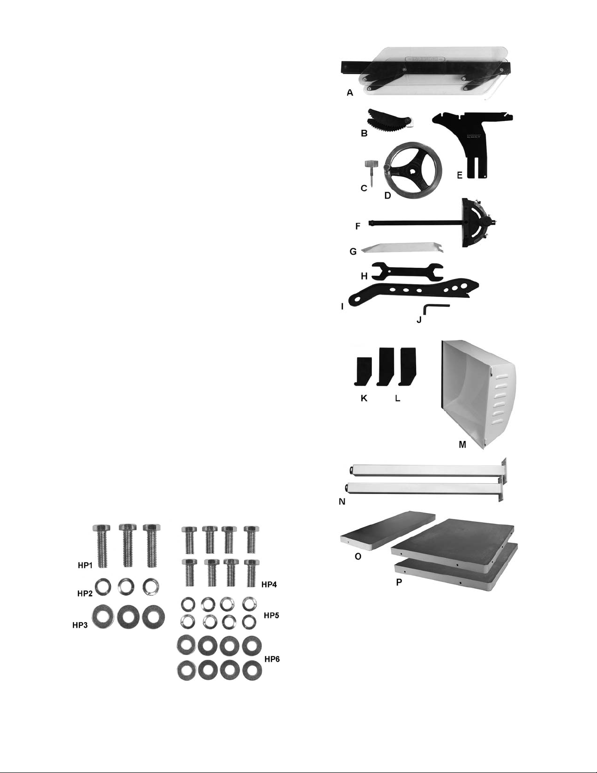
7.2 Shipping contents
Carton contents (see Figure 1)
1 Table saw (not shown)
1 Blade guard – A
1 Anti-kickback pawl assembly – B
1 Lock knob – C
1 Handwheel with sw ivel handle – D
1 Riving knife – E
1 Miter gauge – F
1 Switch support brace – G
1 Arbor wrench – H
1 Push stick – I
1 Hex key 8mm – J
1 Storage hook, small – K
2 Storage hooks, large – L
1 Motor cover – M
2 Legs with leveling feet – N
1 Cast iron table extension, 10-inch – O
2 Cast iron table extensions, 23-inch – P
1 Operator’s Manual (not shown)
1 Warranty Card (not shown)
2 Hardware bags containing:
3 Hex cap screws, 7/16”x1-1/2” – HP1
3 Lock washers, 7/16” – HP2
3 Flat washers, 7/16” – HP3
8 Hex cap screws, 5/16”x3/4” – HP4
8 Lock washers, 5/16” – HP5
8 Flat washers, 5/16” – HP6
Note: Fence and rail assemblies are shipped in
separate cartons.
Figure 2
Figure 1
(items not to scale)
9
Page 10

7.3 Unpacking and cleanup
1. Remove all contents f rom shipping container.
Do not discard any shipping material until saw
is set up and running satisfactorily.
2. Inspect contents for shipping damage. Report
damage, if any, to your local distributor.
3. Compare contents of shipping carton with the
contents list in section 7.2. Also check saw in
case any listed parts have been pre-installed.
Report shortages, if any, to your distributor.
4. Exposed surfaces have been coated with a
protectant. This can be removed with kerosene
or a cleaner-degreaser.
7.4 Installation and leveling
• Tool: 12 mm w rench
1. Remove two screws holding saw to pallet.
2. Carefully move saw to its final locatio n. Final
location for the saw must be level, dry, well
lighted, and have enough room to allow
movement around the saw with long pieces of
wood stock.
3. Level the saw front to back and side to side
using a carpenter’s level placed on the table.
Use shims under the cabinet corners, if
nece ssa ry, b ut m ake sure sa w i s sta b le b ef or e
being placed into service.
7.5 Installing table extensions
• Hardware: (9 each) 7/16” screws (HP1), lock
washers (HP2), flat washers (HP3); and (8
each) 5/16” screws (HP4), lock washers (HP4),
fl at washers (HP6); and (3) table extensions.
• Tools: 17mm wr ench , 12mm wrenc h, st rai ght
edge, lift table or similar supporting device
1. Remove shipping bracket (A, Figure 3) from
table and switch. Keep the upper screw and
washers; they will be used to hold table
extension in p lace.
2. Install the 10-inch table extension to left edge
of saw table with three screws, lock washers
and flat washers. Snug screws, but do not
tighten.
3. Slide extensio n toward front edge of saw table
until the two front edges are flush (D, Figure
4). This will ensure proper guide rail
installation.
Figure 4
4. Use a straight edge (C, Figure 4) to align
extension to saw table and tighten screws.
ASSEMBLY TIP: Align center section first and
tighten center screw almost completely. Then
place wood blocks at outer ends, spanning
main table and extension, and use clamps to
press blocks firmly against tables – this will
bring the outer ends of tables into alignment.
Tighten all three scre ws.
5. Identify the two 23-inch table extensions: the
inner table extension has hole s or slots on all
four edges; the outer table extension has one
blank edge and threaded holes underneath for
leg attachment.
The table extensions are
heavy! Exercise caution and use assistants or a
support device to hold the extensions while
assembling.
Figure 3
IMPORTANT: The tables must be aligned
carefully to allow smooth transition of rip fence
and workpieces over the seams.
6. Install inner table extension (E, Figure 5), w ith
slots toward saw, with three screws and
washers.
7. Follow steps 3 and 4 above. Continue
supporting inner table extension until outer
extension is installed.
8. Install legs (F) beneath outer table extension
(G) with eight screws and washers.
9. Install outer table extension to edge of inner
extension using steps 3 and 4. Rotate leveling
feet on legs as needed.
10
Page 11

Figure 5
7.6 Installing motor cover
1. Install motor cover by aligning pins on cover
with barrels on cabinet (A, Figure 6).
2. Fasten cover by p ulling out latc h (B, Figure 6),
closing door, and releasing latch.
Figure 6
7.7 Installing handwheel
• Hardware: Handle and handwheel, lock knob
• Tool: 3mm hex key
1. Remove tape holding key to shaft.
2. Line up key on shaft with keyway in handwheel
and slide handwheel (C, Figure 7) onto shaft.
3. Tighten set screw on handwheel hub sec ure ly
to hold in place.
4. Insert lock knob (D, Figure 7) into center hole
in shaft and rotate in clockwise direction.
Note: Rotate handwheel in order to free the
packing below the motor.
Figure 7
7.8 Installing storage hooks
• Hardware: Socket head cap screws and
washers (already in cabinet holes)
• Tool: 5mm hex key
Install small hook (E, Figure 7) in upper hole for
miter gauge storage. T he larger hooks (F, Figure 7)
are installed in the lower holes for fence storage.
7.9 Installing blade (not provided)
When installing or changing
saw blade, always disconnect saw from power
source. Failure to comply may cause serious
injury.
• Tool: Arbor wrench
1. Raise blade arbor fully with front handwheel
and lock it at zero degree s by tightening lock
knob in middle of handwheel.
2. Remove arbor nut (A, Figure 8) and flange (B).
3. Place blade on arbor shaft, making sure the
teeth po int down toward f ront of saw. Reinstall
flange and arbor nut.
4. Rotate arbor until hole (C) lines up wit h arbor
lock pin (D). Push pin into hole and hold.
5. Tighten arbor nut with provided wrench.
Figure 8
11
Page 12

7.10 Installing riving knife
• Hardware: rivi n g knife
• Tool: straight edge
1. Loosen handle (E, Figure 9).
2. Push tabs of riving knife into block as far down
as it will go and tighten handle.
Figure 9
3. Install blade (not provided).
4. Lay a straight edge against side of riving knife
and blade (Figure 10). Make sure it contacts
flat surface of blade, not an offset tooth.
5. If knife and blade are not flush, note the
dire c tion in which rivi ng knife needs to m o v e t o
align. Remove riving knife and adjust any of
four set screws (F, Figure 11).
6. Reinstall riving knife and check alignment
again. Repeat as needed until surfaces are
flush.
Figure 11
7.11 Table insert adjustment
• Hardware: Ta ble insert
• Tools: Straight edge, 2.5mm hex key
Install table insert and make it flush with table by
turning any of six leveling screws (G, Figure 12)
while verifying with a straight edge.
Figure 12
Figure 10
12
Page 13

7.12 Installing anti-kickback pawls
and blade guard assembly
1. Install riving knife and table insert.
2. Push the pin (H, Figure 13) at side of pawl
assembly, and slide pawl assembly into recess
of riving knife.
3. Push the pin (I, Figure 14) on rear of blade
guard, and slide it i nto recess at back of rivi ng
knife. Allow front of guard to lower to the table.
Figure 13
5. Fasten switch brace to switch bracket
assembly with the star washer and nut.
6. Align switch and tighten all hardware.
Figure 15
7.15 Miter gauge operation
1. Slide miter gauge into table T-slot.
2. Operate miter gauge by loosening lock knob
(A, Fig. 16) and turning miter body (B) to
desired angle. To move gauge beyond index
stops of 45° and 90°, flip stop (C) out of the
way.
3. Adjust index stops by turning one of three
adjustment screws (D).
Figure 14
7.13 Installing rails and rip fence
With table extensions properly aligned and
secured, the rail and fence assembly can be
mounted to saw. See owner’s manual M-708955Z,
XACTA Fence for JTAS-12-DX, for instructions.
7.14 Installing switch and brace
• Hardware: Swi tch brace
• Tool: 8mm hex key, 8mm wrench
1. Place switch bracket assembly behind both
front fence rail and lip of left table extension.
(Do not place between front fence rail and
table extension; this will cause front rail to
distort and the fence to bind).
2. Loosen (do not remove) screw (A, Figure 15).
3. Slide open tab of switch brace onto t he screw
and washer. Hand tighten only at this time.
4. Remove nut and star washer from screw at
bottom of switch plate.
Figure 16
Note: Always make test cuts. Do not rely solely on
miter gauge indicator marks. Holes are pro vided in
the miter gauge body to allow mounting a woode n
extension fence.
13
Page 14

8.0 Electrical connections
9.0 Adjustments
Electrical connections must
be made by a qualified electrician in
compliance with all relevant codes. This
machine must be properly grounded to pr event
serious or fatal injury.
The JTAS-12-DX is rated for single phase, 230 volt
power only. A plug is not provided.
Confirm power at the site matches that of the saw
before making any electrical connections. Review
the electrical diagram in Section 13.0.
You may either install a plug or “hard-wire” the
saw directly to a control panel. If saw is to be hardwired to a panel, make sure a disconnect is
available for the operator. During hard-wiring,
make sure the fuses have been removed or the
breakers have been tripped in the circuit to which
the machine will be connected. Place a warning
placard on fuse holder or circuit breaker to prevent
it being turned on while saw is being wired.
It is recommended that the JTAS-12-DX Table Saw
be connected to a dedicated 30 amp circuit with
circuit breaker or time delay fuse. Local codes
take precedence over recommendations.
The on/off switch is thermally protected. If the saw
motor is overloaded, or a momentary interruption of
electrical current is sensed, the saw will shut off.
Allow a few minutes for saw to cool down, then
reset by pushing the off button.
8.1 Extension cords
The use of extension cords i s discouraged. Try to
position machines within reach of power source. If
an extension cord becomes necessary, be sure to
use one heavy enough to carry the current your
product will draw. An unde rsized cord will cause a
drop in line voltage resulting in loss of power and
overheating.
Table 1 shows correct size to use depending on
cord length and nameplate ampere rating. If in
doubt, use the next heavier gauge. The smaller the
gauge number, the heavier the cord.
Amp Rating Volts Total length of cord in feet
More
Than
00 06 18 16 16 14
06 10 18 16 14 12
10 12 16 16 14 12
12 16 14 12
Not
More
Than
Extension Cord Recommendations
240 50 100 200 300
AWG
Not
Recommended
Table 1
9.1 Blade raising and tilting
1. To raise or lower saw blade, loose n lock knob
(A, Figure 17) and turn handwheel (B) on the
saw front until desired height is reached.
Tighten lock knob. Blade should be adjusted
no more than 1/8" to 1/4" above top surface of
material being cut.
2. To tilt blade, loosen lock knob (C, Figure 17),
turn handwheel on right of saw cabinet (D)
until desired angle is obtained, then tighten
lock knob .
Figure 17
All following adjustments
must be made with machine disco nnected fr om
power source. Failure to comply may cause
serious injury.
9.2 Blade alignment
• Tool: 8mm hex key, combinati on square, felt-
tip marker
Blade alignment is set by the manufacturer, but
should be verified by the operator. Also after a
period of use, or after relocating saw, the blade
may become misaligned with table. To check and
align blade:
1. Disconnect saw from power source.
2. Remove blade guard and anti-kickback pawls.
3. Use the right T-slot as a shoulder for a
combination square. See Figure 18.
4. Choose a toot h on the far edge of blade and
directly over the insert. Mark the tooth.
5. Measure the distance from side of blade to
right T-slot edge using a combination square.
Note: The square should contact flat surface of
blade between teeth, not a raised tooth edge.
6. Rotate blade toward front so that marked tooth
is just above insert. Measure distance from
marked point of blade to right T-slot edge. The
two measurements should be equal.
14
Page 15

Figure 18
7. If m easurements are not equal, locate the f our
screws that hold table to cabinet (E, Figure
17).
8. Loosen the four screws and bump the table as
needed to align it with blade. Retighten screws
firmly.
9.3 Adjusting 90° and 45° positive
stops
• Tool: 12mm Wrench, combination square
Stops have been set by the manufacturer, but
should be verified by the operator. Also after a
period of use, or after relocating saw, the stops
may need readjusting. To check and adjust the
stop s:
1. Disconnect saw from power source.
2. Raise saw blade to maximum height.
3. Set blade at 90-degrees to table by turning
blade tilting handwheel clockwise as far as it
will go.
4. Place a square on the table and chec k to see
that blade is at 90-degree angle to table
(Fig ure 1 9). M ake s ure squar e is not to uch ing
a blade tooth.
6. Loosen lock nut (A, Figure 20) and turn stop
screw (B) on front trunnion as needed. The
stop screw should contact front trunnion
bracket when blade is 90-degrees to table. Tilt
blade back to 90-degrees and verify.
7. Tighten lock nut (A, Figure 20).
Figure 20
8. Verify pointer accuracy (C, Figure 21). Adjust if
needed.
9. Set blade at 45-degrees to table by turning
blade tilting handwheel counter-clockwise as
far as it will go.
10. P lace an angle measuring device on t he table
and against blade.
11. If blade is not at 45-degrees, loosen lock nut
(D, Figure 21) and t urn stop screw (E) on t he
front trunnion as needed. The stop screw
should contact front trunnion bracket when
blade is 45-degrees to table. (Note: You may
wish to remove front handwheel for better
acce ss to st o p sc r ew.)
12. Verify pointer accuracy (C, Figure 21).
Figure 19
5. If blade is not at 90-degrees, open motor cover
and tilt blade to access the stop screw.
Figure 21
(shown with front handwheel removed)
15
Page 16

9.4 Belt tension and replacement
1. Disconnect machine from power source.
2. Lower blade to its lowest point.
3. Loosen bolt (A, Figure 22).
4. Take tension off belt (B) by lifting up on motor.
5. Remove belt from arbor and motor pulleys.
6. Install new belt. The weight of the motor
should apply sufficient tension to belt. Tighten
bolt (A, Figure 22).
NOTE: New belts may stretch slig htly until they are
worn in. Check belt tension after saw has been
used for a few hours, and adjust if necessary.
10.0 Maintenance
Always disconnect power to
the machine before performing maintenance.
Failure to comply may cause serious injury.
Use vacuum or compressed air to clear out cabinet
interior of sawdust and wood chips. Make sure
motor fan and fan cover are also kept clear of
sawdust.
Use a wire brush to clean worm gears and
trunnions. Apply white lithium grease or powdered
graphite to lubricate worm gears and trunnions.
Keep a light coat of rust-preventive on the table top
when not in use. If rust develops on tabletop,
remove it with WD-40® and a Scotch-Brite™ Hand
Pad.
The saw arbor is press fitted in the saw raising arm
housing. If the arbor ever needs to be rem oved for
bearing replacement, it should be done by a
qualified service technician. Call your customer
service representative at the phone number o n the
front cover.
Figure 22
16
Page 17

11.0 Troubleshooting the JTAS-12-DX Table S aw
11.1 Mechanical Problems
Symptom Possible Cause Correction
Motor will not start. Saw disconnected from power
source.
Fuse blown or circuit breaker tripped. Replace fuse or reset circuit breaker.
Cord damaged. Replace cord.
Low voltage. Check power line for proper voltage.
Open circuit in motor or loose
connection.
Motor will not start:
fuses blow or circuit
breakers trip.
Blade will not come up
to speed.
Motor overheats. Motor overloaded. Reduce load on motor.
Motor stalls, resulting
in blown fuses or
tripped circuit.
Short circuit in line cord or plug. Inspect cord or plug for damaged
Short circuit or loose connections. Inspect all connections at junction box and
Incorrect fuses or circuit breakers in
power line.
Extension cord too light or too long. Replace with adequate size electrical
Low voltage. Check power line for proper voltage.
Air circulation through motor
restricted.
Motor overloaded. Reduce load on motor.
Short circuit in motor or loose
connections.
Low voltage. Correct the low voltage conditions.
Check plug or hard-wired connections.
Contact local electric company.
Inspect incoming leads for loose or open
connections.
insulation and shorted wires.
motor for loose or shorted terminals or
worn insulation.
Install correct fuses or circuit breakers.
cord.
Contact local electric company.
Clean motor fan with compressed air to
restore normal air circulation.
Inspect connections on motor for loose or
shorted terminals or worn insulation.
Incorrect fuses or circuit breakers in
power line.
Loud, repetitive noise
coming from machine.
Saw vibrates
excessively.
Pulley setscrews or keys are missing
or loose.
Motor fan is hitting cover. Tighten fan or shim cover.
V-belt is defective. Replace V-belt.
Cabinet on uneven floor. Reposition on flat, level surface.
Saw blade is damaged. Replace blade.
Loose hardware. Tighten hardware.
Pulley bent. Inspect and replace pulley.
Improper motor mounting. Check and adjust motor, tighten bolt(s).
V-belt is defective. Replace V-belt.
Install correct fuses or circuit breakers.
Inspect keys and setscrews. Replace or
tighten if necessary.
Table 2
17
Page 18

11.2 Operational Problems
Symptom Possible Cause Correction
Machine slows when
operating.
Blade not square with
miter slot, or fence not
square to blade.
Does not make
accurate 45- or 90degree cuts.
Rip fence binds on
guide rails.
Material binds in blade
when ripping.
Material ki cked back
from blade.
Applying too much pressure to
workpiece.
Belt loose. Tension belt.
Blade is warped. Replace saw blade.
Fence not parallel to blade. Adjust fence parallel to blade.
Table not parallel to blade. Adjust table parallel to blade.
Stops not adjusted properly. Check blade with angle measuring device,
Miter gauge out of adjustment. Use a square or angle-setting device to
Guide rails or extension table not
properly installed.
Fence locking system not adjusted
properly.
Fence not aligned with blade. Check and adjust fence.
Warped wood. Select different stock.
Applying excessive pressure to
workpiece.
Riving knife not aligned with blade. Adjust riving knife.
Fence out of alignment. Align fence wi th miter slot.
Riving knife not aligned with blade. Align riving knife with blade.
Feed workpiece more slowly.
and adjust stops.
adjust miter gauge to blade.
Re-assemble according to owner’s
manual.
Use set screws to adjust tension against
guide tube.
Feed workpiece more slowly.
Feeding stock without a fence. Always use fence or similar guide to feed
stock; do not feed freehand.
Dull blade. Replace blade.
Blade does not rise or
tilt freely.
Saw makes
unsatisfactory cuts.
Releasing material before it clears
blade.
Anti-kickback pawls are dull. Replace anti-kickback pawls, or resharpen
Sawdust/debris in raising and tilting
mechanisms.
Dull blade. Sharpen or replace blade.
Blade mounted backward. Turn blade around.
Gum or pitch on blade. Remove blade and clean.
Incorrect b lade f or desired cut. Change blade to correct style, tooth pitch,
Gum or pitch on table. Clean table.
Table 3
Push material completely past blade
before releasing it.
their points.
Clean and regrease problem areas.
etc.
12.0 Replacement Parts
Replacement parts are listed on the followi ng pages. To order parts or reach our service departm ent, call 1800-274-6848 Monday through Friday (see our website for business hours, www.jettools.com). Having the
Model Number and Serial Number of your machine available when you call will allow us to serve you quickly
and accurately.
18
Page 19

12.1.1 Table and Cabinet Assembly (JTAS-12-DX) – Exploded View
19
Page 20

12.1.2 Table and Cabinet Assembly (JTAS-12-DX) – Parts List
Index No Part No Description Size Qt y
1 ................ JTAS10-1 .................. Lock Knob ........................................................ .............................................. 1
2 ................ JTAS10-2 .................. Miter Gauge Body ............................................ .............................................. 1
3 ................ TS-1540031 .............. Hex Nut ............................................................ M5 ......................................... 3
4 ................ JTAS10-4 .................. Poin ter ............................................................. .............................................. 1
5 ................ JTAS10-5 .................. Stop Link .......................................................... .............................................. 1
6 ................ TS-1521011 .............. Socket Set Screw ............................................ M4x4 ...................................... 1
7 ................ JTAS10-7 .................. Special Pin ....................................................... M3x6 ...................................... 1
8 ................ TS-2205201 .............. Hex Cap Screw ................................................ M5x20 .................................... 3
9 ................ JTAS10-9 .................. Guide Bar......................................................... .............................................. 1
10 .............. JTAS10-10 ................ Guide Washer .................................................. .............................................. 1
11 .............. JTAS10-11 ................ Flat Head Screw .............................................. M6x8 ...................................... 1
.................. JTAS10-MG .............. Miter Gauge Assembly (#1 thru 11) ................. .............................................. 1
12 .............. TS-0267041 .............. Socket Set Screw ............................................ 1/4"-20x3/8” ........................... 6
13 .............. JTAS12DX-13 ........... Table Insert ...................................................... .............................................. 1
13A ............ JTAS12DX-13A ......... Dado Insert ...................................................... .............................................. 1
14 .............. JTAS12DX-14 ........... Table ................................................................ .............................................. 1
15 .............. JTAS12DX-15 ........... Left Table Extension ........................................ 31-1/2”L x 10”W ..................... 1
16 .............. JTAS12DX-16 ........... Inner Table Extension ...................................... 31-1/2”L x 23”W ..................... 1
17 .............. JTAS12DX-17 ........... Outer Table Extension ..................................... 31-1/ 2”L x 23”W ..................... 1
18 .............. TS-0061051 .............. Hex Cap Screw ................................................ 7/16”-14x1-1/2” ...................... 9
19 .............. TS-0720101 .............. Lock Washer .................................................... 7/16” ...................................... 9
20 .............. TS-0680051 .............. Flat Washer ..................................................... 7/16” .................................... 13
21 .............. JTAS12DX-21 ........... Leg ................................................................... .............................................. 2
22 .............. JTAS10-22W ............. Switch Plate ..................................................... .............................................. 1
23 .............. JTAS12-23 ................ Magn etic Switch .............................................. 5HP, 1 Ph, 230V .................... 1
24 .............. TS-081C052 .............. Pan Head Screw .............................................. #10-24x3/4 ............................ 1
25 .............. TS-0680031 .............. Flat Washer ..................................................... 5/16” ...................................... 8
26 .............. JTAS10-26 ................ Strain Relief Bushing ....................................... .............................................. 2
27 .............. JTAS10-27 ................ Strain Relief Bushing ....................................... .............................................. 2
28 .............. JTAS10-28 ................ Tap Screw........................................................ M5x10 .................................. 10
29 .............. JTAS10-29 ................ Cord Plate ........................................................ .............................................. 1
30 .............. JTAS12DX-30 ........... I dentification Plate ........................................... .............................................. 1
31 .............. JTAS12DX-31 ........... Power Cord (switch to motor) .......................... 12AWG x 3C ......................... 1
32 .............. JTAS12DX-32 ........... Power Cord ...................................................... 12AWG x 3C ......................... 1
33 .............. JTAS10-33 ................ Power Cord Sleeve .......................................... .............................................. 1
34 .............. JTAS10L-34 .............. Tilt Scale .......................................................... .............................................. 1
35 .............. JTAS10-35 ................ Warning Label.................................................. .............................................. 1
36 .............. JTAS10-36 ................ JET Label......................................................... .............................................. 1
37 .............. TS-0720081 .............. Lock Washer .................................................... 5/16” ...................................... 8
38 .............. JTAS12DX-38 ........... Cabin et ............................................................ .............................................. 1
39 .............. TS-1482101 .............. Hex Cap Screw ................................................ M6x50 .................................... 1
40 .............. TS-0680021 .............. Flat Washer ..................................................... 1/4" ........................................ 2
41 .............. JTAS10-41 ................ Sprin g .............................................................. .............................................. 1
42 .............. JTAS10-42 ................ Foam Strip ....................................................... .............................................. 1
43 .............. JTAS12DX-43 ........... Motor Cover ..................................................... .............................................. 1
44 .............. TS-1541021 .............. Nylon Insert Lock Nut ...................................... M6 ......................................... 1
45 .............. JTAS10-45 ................ Handl e ............................................................. .............................................. 1
47 .............. TS-0210011 .............. Socket Head Cap Screw.................................. 7/16”-14x3/4” ......................... 4
48 .............. TS-0680011 .............. Flat Washer ..................................................... 3/16” ...................................... 2
49 .............. JTAS12DX-49 ........... Lower Panel ..................................................... .............................................. 1
50 .............. JTAS10L-50N............ Dust Hose Adapter .......................................... .............................................. 1
51 .............. JTAS12DX-51 ........... Switch Brace Kit............................................... .............................................. 1
52 .............. TS-081C062 .............. Screw ............................................................... #10-24x1 ............................... 1
53 .............. TS-0560071 .............. Hex Nut ............................................................ #10-24 ................................... 1
54 .............. TS-0733031 .............. Star Washer ..................................................... #10 ........................................ 1
55 .............. JTAS10L-55 .............. Hook (large) ............................................................. ...................................... 2
56 .............. TS-0680021 .............. Flat Washer ............................................................. 1/4" ................................ 6
57 .............. TS-0720071 .............. Lock Washer ............................................................ 1/4" ................................ 6
58 .............. TS-0207031 .............. Socket Head Cap Screw.......................................... 1/4"-20x5/8” .................. 6
59 .............. JTAS10L-59 .............. Hook (small)............................................................. ...................................... 1
20
Page 21

Index No. Part No. Description Size Qty
60 .............. TS-0561011 .............. Hex Nut .................................................................... 1/4"-20” ......................... 6
61 .............. JTAS10L-61 .............. Electrical Box ........................................................... ...................................... 1
62 .............. TS-0081031 .............. Hex Cap Screw ........................................................ 5/16” x3/4” ..................... 8
63 .............. TS-1540071 .............. Hex Nut .................................................................... M10 ............................... 2
64 .............. JTAS12DX-64 ........... Leveling Foot ........................................................... M10 x75 ........................ 2
.................. STRIPE-1-3/4 ............ Stripe (not shown).................................................... 1-3/4” wide .......
per 9.12 ft.
21
Page 22

12.2.1 Trunnio n and Motor Assembly (JTAS-12-DX) – Exploded View
22
Page 23

12.2.2 Trunnio n and Motor Assembly (JTAS-12-DX) – Parts List
Index No Part No Description Size Qty
101 ............ JTAS12L-101 ............ Arbor Nut ................................................................. ...................................... 1
102 ............ JTAS12DX-102 ......... Arbor Flange ............................................................ ...................................... 1
104 ............ JTAS12DX-104 ......... Arbor with Flange..................................................... ...................................... 1
105 ............ JTAS12DX-105 ......... Key .......................................................................... 1/4”x1/4”x1-3/4”............. 2
106 ............ BB-6005ZZ ................ Ball Bearing ............................................................. 6005ZZ.......................... 2
107 ............ JTAS12DX-107 ......... Wave Washer .......................................................... ...................................... 4
108 ............ JTAS12DX-108 ......... Rear Bearing Load Spacer ...................................... ...................................... 1
108-1 ......... JTAS12DX-108-1 ...... Front Bearing Load Spacer...................................... ...................................... 1
109 ............ TS-0267041 .............. Socket Set Screw .................................................... 1/4"-20x3/8” ................ 10
110 ............ JTAS-12DX-110 ........ Arbor Pulley ............................................................. ...................................... 1
111 ............ TS-0209081 .............. Socket Head Cap Screw.......................................... 3/8”-16x1-3/4” ............... 1
112 ............ JTAS10DX-112 ......... Key........................................................................... 1/4" x1/4”x45mm ........... 1
113 ............ TS-0720091 .............. Lock Washer ............................................................ 3/8” .............................. 10
114 ............ JTAS12DX-114 ......... Arbor Bracket ........................................................... ...................................... 1
115 ............ JTAS12-115 .............. Spanner Nut............................................................. ...................................... 1
116 ............ TS-0561081 .............. Nylon Hex Nut.......................................................... 3/4"-10 .......................... 1
117 ............ JTAS10-117 .............. Sprin g Pin ................................................................ M6x50 ........................... 1
118 ............ JTAS10-118 .............. Key ........................................................................... 1/4"x1/4”x2-5/16” .......... 1
119 ............ TS-0680051 .............. Flat Washer ............................................................. 7/16” .............................. 2
120 ............ TS-0091031 .............. Hex Cap Screw ........................................................ 7/16”-14x1”.................... 2
121 ............ JTAS10DX-121 ......... Shaft ........................................................................ ...................................... 1
122 ............ JTAS10-122 .............. Motor Bracket .......................................................... ...................................... 1
123 ............ JTAS10-123 .............. Pin............................................................................ ...................................... 1
124 ............ JTAS10L-124 ............ Spring Clip ............................................................... ...................................... 2
125 ............ JTAS12DX-125 ......... Poly V-Belt ............................................................... PJ250 ............................ 1
126 ............ JTAS10DX-126 ......... Motor Mounting Bracket........................................... ...................................... 1
127 ............ JTAS10-127N............ Motor Pulley ............................................................. ...................................... 1
128 ............ TS-0680031 .............. Flat Washer ............................................................. 5/16” ............................ 10
129 ............ TS-0720081 .............. Lock Washer ............................................................ 5/16” .............................. 9
130 ............ TS-0081031 .............. Hex Cap Screw ........................................................ 5/16”-18x3/4”................. 4
131 ............ JTAS12DX-131 ......... Motor........................................................................ 5HP 1PH 230V only ...... 1
.................. JTAS10-131-017 ....... Centrifugal Switch Assembly (not shown) ............... ...................................... 1
.................. JTAS10-131D............ Fan Cover (not shown) ............................................ ...................................... 1
.................. JTAS10-131F ............ Motor Fan (not shown)............................................. ...................................... 1
.................. JTAS10-1315B .......... Start Capacitor (not shown) ..................................... 600MFD/250VAC .......... 1
.................. JTAS10-1315A .......... Run Capacitor (not shown) ...................................... 80uF/350VAC ............... 1
132 ............ TS-0209071 .............. Socket Head Cap Screw.......................................... 3/8”-16x1-1/2” ............... 6
133 ............ JTAS10DX-133 ......... Rear Trunnion Bracket............................................. ...................................... 1
134 ............ TS-0561031 .............. Hex Nut .................................................................... 3/8”-16........................... 5
135 ............ TS-0209051 .............. Socket Head Cap Screw.......................................... 3/8-“16x1”...................... 4
136 ............ JTAS10-136 .............. Sprin g Pin ................................................................ M8x25 ........................... 4
137 ............ TS-0561081 .............. Hex Nut .................................................................... 3/4"-10 .......................... 1
138 ............ JTAS10-138 .............. Fiber Washer ........................................................... ...................................... 4
139 ............ JTAS10DX-139 ......... Rear Trunnion ......................................................... ...................................... 1
140 ............ JTAS10-140 .............. Rear Bushing ........................................................... ...................................... 2
140-1 ......... JTAS10DX-140 ......... Fron t Bushing .......................................................... ...................................... 1
141 ............ JTAS12DX-141 ......... Yoke......................................................................... ...................................... 1
142 ............ TS-0270011 .............. Socket Set Screw .................................................... 5/16”-18x1/4”................. 4
143 ............ JTAS10-143 .............. Col lar ....................................................................... ...................................... 2
144 ............ JTAS12DX-144 ......... Shaft ........................................................................ ...................................... 1
145 ............ JTAS10-145 .............. Sprin g Pin ................................................................ M5x30 ........................... 2
146 ............ JTAS10-146 .............. Worm (Left thread)................................................... ...................................... 1
146-1 ......... JTAS10DX-146 ......... Worm (Right thread) ................................................ ...................................... 1
147 ............ JTAS10-147 .............. Lock Pin ................................................................... ...................................... 4
148 ............ JTAS10-148 .............. Key ........................................................................... M5x35 ........................... 2
149 ............ TS-0208021 .............. Socket Head Cap Screw.......................................... 5/16”-18x1/2”................. 4
150 ............ JTAS12DX-150 ......... Dust Deflector .......................................................... ...................................... 1
151 ............ JTAS10L-151N.......... Hose Clamp ............................................................. ...................................... 2
152 ............ JTAS10DX-152 ......... Front Trunnion ......................................................... ...................................... 1
.................. JTAS12DX-TA........... Trunni on Assembly (#113, 135, 136, 139 thru 141, 152) .............................. . 1
23
Page 24

Index No. Part No. Description Size Qty
153 ............ TS-0051021 .............. Hex Cap Screw ........................................................ 5/16”-18x5/8”................. 2
154 ............ TS-0561021 .............. Hex Nut .................................................................... 5/16”-18......................... 2
155 ............ JTAS10-155A ............ Lock Knob ................................................................ ...................................... 2
156 ............ JTAS10-156 .............. Fiber Washer ........................................................... ...................................... 2
157 ............ TS-0208061 .............. Socket Head Cap Screw.......................................... 5/16”-18x1”.................... 2
158 ............ JTAS10DX-158 ......... Front Trunnion Bracket ............................................ ...................................... 1
159 ............ JTAS10-159 .............. Handwh eel Handle .................................................. ...................................... 2
160 ............ JTAS10-160 .............. Handwheel ............................................................... ...................................... 2
161 ............ JTAS10-161 .............. Shield Plate.............................................................. ...................................... 1
162 ............ TS-0813022 .............. Round Head Screw.................................................. 1/4"-20x3/8” .................. 1
163 ............ JTAS10-163 .............. Poin ter ..................................................................... ...................................... 1
164 ............ JTAS10-164 .............. Poin ter Bracket ........................................................ ...................................... 1
165 ............ TS-081C102 .............. Pan Head Screw ...................................................... #10-24x2” .... .................. 2
166 ............ JTAS10DX-166 ......... Guide Block ............................................................. ...................................... 1
167 ............ TS-0680041 .............. Flat Washer ............................................................. 3/8” ................................ 1
169 ............ JTAS12DX-169 ......... Tilt Shaft................................................................... ...................................... 1
170 ............ JTAS12-170 .............. Wrench .................................................................... ...................................... 1
171 ............ JTAS10L-171 ............ Hose ........................................................................ 700mm .......................... 1
172 ............ JTAS10L-172 ............ Plate......................................................................... ...................................... 1
173 ............ TS-0208041 .............. Socket Head Cap Screw.......................................... 5/16”-18x3/4”................. 3
174 ............ JTAS12DX-174 ......... Chip Plate ................................................................ ...................................... 1
175 ............ TS-0680011 .............. Flat Washer ............................................................. 3/16 ............................... 3
176 ............ TS-0720051 .............. Lock Washer ............................................................ #10 ................................ 3
177 ............ JTAS10L-177 ............ Hex Cap Bolt............................................................ #10-24x3/8 .................... 3
178 ............ JTAS10L-178 ............ Special Screw .......................................................... ...................................... 1
179 ............ JTAS10L-179A .......... Arbor Lock Ins ert Assembly (#179-1 thru 179-5) ..... ...................................... 1
179-1 ......... JTAS10L-179-1 ......... Arbor Lock Insert ..................................................... Ø8 ................................. 1
179-2 ......... JTAS10L-179-2 ......... Spring ...................................................................... ...................................... 1
179-3 ......... JTAS10L-179-3 ......... Insert Block .............................................................. ...................................... 1
179-4 ......... TS-1502051 .............. Socket Head Cap Screw.......................................... M5 x 20 ......................... 2
179-5 ......... TS-1521041 .............. Socket Set Screw .................................................... M4 x 10 ......................... 1
181 ............ TS-0640071 .............. Nylon Insert Lock Nut .............................................. 1/4-20 ............................ 3
182 ............ JTAS10L-182N.......... Spacer ..................................................................... ...................................... 2
183 ............ JTAS12DX-183 ......... Guide Plate .............................................................. ...................................... 1
184 ............ TS-0245051 .............. Flat Head Socket Screw .......................................... 1/4-20x1 ........................ 2
185 ............ JTAS10L-185 ............ Special Screw .......................................................... ...................................... 1
186 ............ JTAS12DX-186 ......... Extension Support Plate .......................................... ...................................... 1
187 ............ TS-1541021 .............. Nylon Insert Lock Nut .............................................. M6 ................................. 1
188 ............ JTAS10L-188 ............ Plate......................................................................... ...................................... 1
189 ............ JTAS12DX-189 ......... Riving Knife Ex tension Plate.................................... ...................................... 1
190 ............ TS-1513021 .............. Flat Head Socket Screw .......................................... M5x12 ........................... 2
191 ............ JTAS10L-191 ............ Clamping Block ........................................................ ...................................... 1
192 ............ JTAS10L-192 ............ Sprin g ...................................................................... ...................................... 1
193 ............ JTAS10L-193 ............ Clamping Block ........................................................ ...................................... 1
194 ............ TS-1514031 .............. Flat Head Socket Screw .......................................... M6X20........................... 2
195 ............ JTAS10L-195 ............ Locking Handle ........................................................ ...................................... 1
196 ............ TS-1541031 .............. Nylon Insert Lock Nut .............................................. M8 ................................. 1
197 ............ JTAS12DX-197 ......... Spring Shim Ring ..................................................... ...................................... 1
198 ............ JTAS12DX-198 ......... C-Ring...................................................................... S58................................ 1
199 ............ JTAS12DX-199 ......... Guide Block ............................................................. ...................................... 1
24
Page 25

12.3.1 Blade Guard Assembly (JTAS-12-DX) – Exploded View
25
Page 26

12.3.2 Blade Guard Assembly (JTAS-12-DX) – Parts List
Index No Part No Description Size Qty
1 ................ JTAS12DX-301 ......... Riving Knife ............................................................. ...................................... 1
.................. JTAS12DX-BGA........ Blade Guard Assembly (#2 thru 16, 22, 24) ............ ...................................... 1
2 ................ JTAS12DX-302 ......... Bushing .................................................................... ...................................... 2
3 ................ JTAS12DX-303 ......... Blade Guard Body ................................................... ...................................... 1
4 ................ JTAS12DX-304 ......... Blade Guard Side Shield ......................................... ...................................... 2
5 ................ JTAS12DX-305 ......... Linking Plate ............................................................ ...................................... 4
6 ................ TS-1550041 .............. Flat Washer ............................................................. M6 ................................. 8
7 ................ TS-1514021 .............. Flat Head Socket Screw .......................................... M6x16 ........................... 8
8 ................ JTAS12DX-308 ......... Fron t Shield ............................................................. ...................................... 1
9 ................ PM2000-309.............. Bushing .................................................................... ...................................... 1
10 .............. PM2000-310.............. Top Sight Shield ...................................................... ...................................... 1
11 .............. TS-1541021 .............. Nylon Insert Lock Nut .............................................. M6 ................................. 8
12 .............. TS-081B012 .............. Pan Head Screw ...................................................... #8-32x1/4 ...................... 2
13 .............. PM2000-313.............. Roll Pin .................................................................... 5x25 .............................. 1
14 .............. PM2000-314.............. Roll Pin .................................................................... 5x12 .............................. 2
15 .............. PM2000-315.............. Lock Pin ................................................................... ...................................... 1
16 .............. PM2000-316.............. Roll Pin .................................................................... 4x28 .............................. 1
.................. JTAS12DX-AKPA...... Anti-Kickback Pawl Assembly (#17 thru 24) ........... ...................................... 1
17 .............. JTAS12DX-317 ......... Left Anti-Kickback Pawl ........................................... ...................................... 1
18 .............. JTAS12DX-318 ......... Right Anti-Kickback Pawl ......................................... ...................................... 1
19 .............. PM2000-318.............. Pawl Base ................................................................ ...................................... 1
20 .............. JTAS12DX-320 ......... Flange ...................................................................... ...................................... 1
21 .............. PM2000-320.............. Lock Pin ................................................................... ...................................... 1
22 .............. PM2000-321.............. Spring ...................................................................... ...................................... 2
23 .............. JTAS12DX-323 ......... Flange ...................................................................... ...................................... 1
24 .............. PM2000-322.............. E-Clip ....................................................................... E5.................................. 2
26
Page 27

13.0 Electrical Connections
27
Page 28

427 New Sanford Road
LaVergne, Tennessee 37086
Phone: 800-274-6848
www.j ettools.com
28
 Loading...