

Page 1
This manual is bookmarked
This .pdf document is bookmarked
Operating Instructions and Parts Manual
20-inch Planer
Models JW P-2 08 and JWP-208 HH
JET
427 New Sanford Road
LaVergne, Tennessee 37086 Part No. M-708528
Ph.: 800-274-6848 Revision J3 12/2014
www.jettools.com Copyright © 2014 JET
Model JWP-208HH shown
Page 2

Warranty and Service
JET warrants every product it sells against manufacturers’ defects. If one of our tools needs service or repair, please
contact Technical Service by calling 1-800-274-6846, 8AM to 5PM CST, Monday through Friday.
Warranty Period
The general warranty lasts for the time period specified in the literature included with your product or on the official
JET branded website.
• JET products carry a limited warranty which varies in duration based upon the product. (See chart below)
• Accessories carry a limited warranty of one year from the date of receipt.
• Consumable items are defined as expendable parts or accessories expected to become inoperable within a
reasonable amount of use and are covered by a 90 day limited warranty against manufacturer’s defects.
Who is Covered
This warranty covers only the initial purchaser of the product from the date of delivery.
What is Co vered
This warranty covers any defects in workmanship or materials subject to the limitations stated below. This warranty
does not cover failures due directly or indirectly to misuse, abuse, negligence or accidents, normal wear-and-tear,
improper repair, alterations or lack of maintenance.
Warranty Limitations
Woodworking products with a Five Year Warranty that are used for commercial or industrial purposes default to a
Two Year Warranty. Please contact Technical Service at 1-800-274-6846 for further clarification.
How to Get Technical Support
Please contact Technical Service by calling 1-800-274-6846. Please note that you will be asked to provide proof
of initia l p u rch a s e whe n calling. If a product requires further inspection, the Technical Service representative will
explain and assist with any additional action needed. JET has Authorized Service Centers located throughout the
United States. For the name of an Authorized Service Center in your area call 1-800-274-6846 or use the Service
Center Locator on the JET website.
More Informa tion
JET is constantly adding new products. For complete, up-to-date product information, check with your local distributor
or visit the JET website.
How State Law Appli es
This warranty gives you specific legal rights, subject to applicable state law.
Limitations on This Warranty
JET LIMITS ALL IMPLIED WARRANTIES TO THE PERIOD OF THE LIMITED WARRANTY FOR EACH PRODUCT.
EXCEPT AS STATED HEREIN, ANY IMPLIED WARRANTIES OF MERCHANTABILITY AND FITNESS FOR A
PARTICULAR PURPOSE ARE EXCLUDED. SOME STATES DO NOT ALLOW LIMITATIONS ON HOW LONG AN
IMPLIED WARRANTY LASTS, SO THE ABOVE LIMITATION MAY NOT APPLY TO YOU.
JET SHALL IN NO EVENT BE LIABLE FOR DEATH, INJURIES TO PERSONS OR PROPERTY, OR FOR
INCIDENTAL, CONTINGENT, SPECIAL, OR CONSEQUENTIAL DAMAGES ARISING FROM THE USE OF OUR
PRODUCTS. SOME STATES DO NOT ALLOW THE EXCLUSION OR LIMITATION OF INCIDENTAL OR
CONSEQUENTIAL DAMAGES, SO THE ABOVE LIMITATION OR EXCLUSION MAY NOT APPLY TO YOU.
JET sells through distributors only. The specifications listed in JET printed materials and on official JET website are
given as general information and are not binding. JET reserves the right to effect at any time, without prior notice,
those alterations to parts, fittings, and accessory equipment which they may deem necessary for any reason
whatsoever. JET
Product Listing with Warranty Period
90 Days – Parts; Consumable items; Light-Duty Air Tools
1 Year – Motors; Machine Accessories; Heavy-Duty Air Tools; Pro-Duty Air Tools
2 Year – Metalworking Machinery; Electric Hoists, Electric Hoist Accessories
5 Year – Woodworking Machinery
Limited Lifetime – JET Parallel clamps; VOLT Series Electric Hoists; Manual Hoists; Manual Hoist
Accessories; Shop Tools; Warehouse & Dock products; Hand Tools
NOTE: JET is a division of JPW Industries, Inc. References in this document to JET also apply to JPW Industries,
Inc., or any of its successors in interest to the JET brand.
®
branded products are not sold in Canada by JPW Industries, Inc.
2
Page 3

Table of Contents
Warranty and Servic e .............................................................................................................................. 2
Table of Contents .................................................................................................................................... 3
Warnings ................................................................................................................................................. 4
Stand Mounting Holes ............................................................................................................................. 5
Features .................................................................................................................................................. 6
Specifica tions ................................................................................................................ .......................... 6
Recei ving ................................................................................................................................................ 7
Installation & Assembly ............................................................................................................................ 7
Starter Box ........................................................................................................................................... 7
Handwheel ........................................................................................................................................... 8
Table Extension Rollers (JWP-208 only) .............................................................................................. 8
Extension Tables (JWP-208HH only).................................................................................................... 8
Dust Collection Hood ........................................................................................................................... 8
Electri c al Connec tions ............................................................................................................................. 9
Extension Cords................................................................................................................................... 9
Adjustments ................................................................................................................... ......................... 9
Belt and Pulleys ................................................................................................................................... 9
Table Roller s ...................................................................................................................................... 10
Overview ........................................................................................................................................ 10
Adjusting Table Extension Rollers ................................................................................................... 11
Adjusting Depth of Cut ....................................................................................................................... 12
Cutterhead Adj ustment....................................................................................................................... 12
Overview ........................................................................................................................................ 12
Knife Adjustment (Model JWP-208 only) ......................................................................................... 12
Replacing & Resetting Knives (Model JWP-208 only) ......................................................................... 13
Replacing or Rotating Knife Inserts (Model JWP-208HH only) ............................................................ 14
Checking Work Tabl e P ar allel to Cutterhead ...................................................................................... 14
Adjusting Work Table Parallel to Cutterhead....................................................................................... 15
Anti-Kickback Fingers ........................................................................................................................ 16
Adjusting I nfeed & Outfeed Roller Spring Tension .............................................................................. 16
Height of Infeed Roller , Chipbreaker, Pressure Bar & Outfeed Roller .................................................. 16
Feed Speed Control ........................................................................................................................... 17
Changing Accessories for Lowest Feed Speed ................................................................................... 17
Return Rollers .................................................................................................................................... 17
Maintenance .......................................................................................................................................... 18
Lubrication............................................................................................................................................. 18
Troubleshooting ..................................................................................................................................... 20
Operating P ro blems ........................................................................................................................... 20
Mechanical and Elec trical Problems ................................................................................................... 20
Optional Accessories ............................................................................................................................. 2 2
Ordering Replacement Parts.................................................................................................................. 22
Parts ..................................................................................................................................................... 22
Head Assembly – Parts List ............................................................................................................... 22
Head Assembly – Exploded Vi ew ....................................................................................................... 25
Table and Roller – Parts and Assembly .............................................................................................. 26
Stand and Motor – Part s and Assembly .............................................................................................. 27
Base and Column – Parts Li st ............................................................................................................ 28
Base and Column – Assembly............................................................................................................ 29
Gearbox – Parts List .......................................................................................................................... 30
Gearbox – Assembly .......................................................................................................................... 31
Wiring Diagrams .................................................................................................................................... 32
230V 3HP Single Phase ..................................................................................................................... 32
230V 5HP Single Phase ..................................................................................................................... 33
230V 5HP Three Phase ..................................................................................................................... 34
460V 5HP Three Phase ..................................................................................................................... 35
3
Page 4

Warnings
Read the manual. Always read the owner’s manual carefully before attempting to use the machine.
Know the limitati ons and hazards a s sociated with the use of this pl aner .
Installation. If mounting m achine to the fl oor, use high quali ty anchor bol ts through the m ounting holes
on the base. If using a mobil e base, be sure t o loc k the wheels.
Eye protection. Always wear approv ed safety goggles, glasses, or a face shield when o perating this
machine. NOT E: Common eyeglasses are o nly impact resistant, t hey are not safety glasses. Also use
face or dust mask if the cutting operation is dusty.
Dress code. Do not wear loose cl othi ng, neckti es, j ewelry, or glov es that can get caught i n moving parts.
Confine long hair. Keep sleeves above the elbow.
Placement. Place machine so that potential kickback area is not in line with aisles, doorways, wash
stations or other work areas. Do n ot use machine in a damp or wet loc ation, or ex pose to r ain. Keep work
area well lighted.
Electrical g rounding. Your machi ne must be electricall y grounded. If a cord and pl ug are used, make
certain t he groundi ng l ug connect s to a suitabl e gr ound. F ollow the groundi ng proc edure i ndi cated by the
National Elect rical Code.
Guards. Be sure machine guards are in pl ace and in good working order. Do not operate while gear
cover is open. If a guard must be removed for adjustments or maintenance, it should be reinstalled
immediately upon c om pletion of the procedure and before operating the machine.
Housekeeping. Before turning on m achi ne, remove all extra equi pment such a s keys, wrenches, scrap,
stock, and cleaning rags from the machine. Keep the area around machine clean and free of scrap
material and sawdust to m inimize the danger of slippi ng.
Power off. Make sure the machine i s either unplugged or electri cally disconnect ed and locked out when
performi ng maintenance or serv ice work. Also, make sure switc h is in OFF position before pl ugging in
power cord. Never leave the machine running unattended. Do not leave machine until it comes to a
complete stop.
Cutterhead. Keep knives sharp and free of all rust and pitch. Make sure gib screws are tightened
securely.
Work piece. Chec k m ater ial f or l oose knots, n ai l s and other def ect s that c an dam age k niv es and po se a
safety hazard for the operator.
Keep hands away from feed r oller s and cut terhead while operating.
Use the proper exten sion cord. Make sure your extension cord i s in good condition. When using an
extension cord, be sure to use one heavy enough to carry the current your product will draw. An
undersized cord will cause a drop in line voltage resulting in loss of power and overheating. For runs up to
25 feet, use an 18 AWG or larger gauge cor d.
Do not op e r a te this machine while under the influence of drugs, alcohol or any medic ation.
If you are not thoroughl y f amiliar wit h the operati on of wood planers, obt ai n advi ce from your supervi sor,
instructor or other qualified person.
Health haz ards. Som e dust creat ed by p o wer sandi ng, sawing, gr indi ng, dri lli ng and other c onstr ucti on
activities contains chemicals known to cause cancer, birth defects or other reproductiv e harm. Some
examples of these chemicals are:
• Lead from lead-based paint .
• Crystalli ne sil ic a from bricks and cement and other masonry products.
• Arsenic and chromium from chemically-treated lumber.
4
Page 5
Your risk from these exposures v ari es, dependi ng on how often you do thi s type of work. To reduce your
exposure to these chemi cals, work in a well-ventil ated area, and work with approved safet y equipment,
such as those dust masks that ar e specif ically designed to filter out microscopic particles.
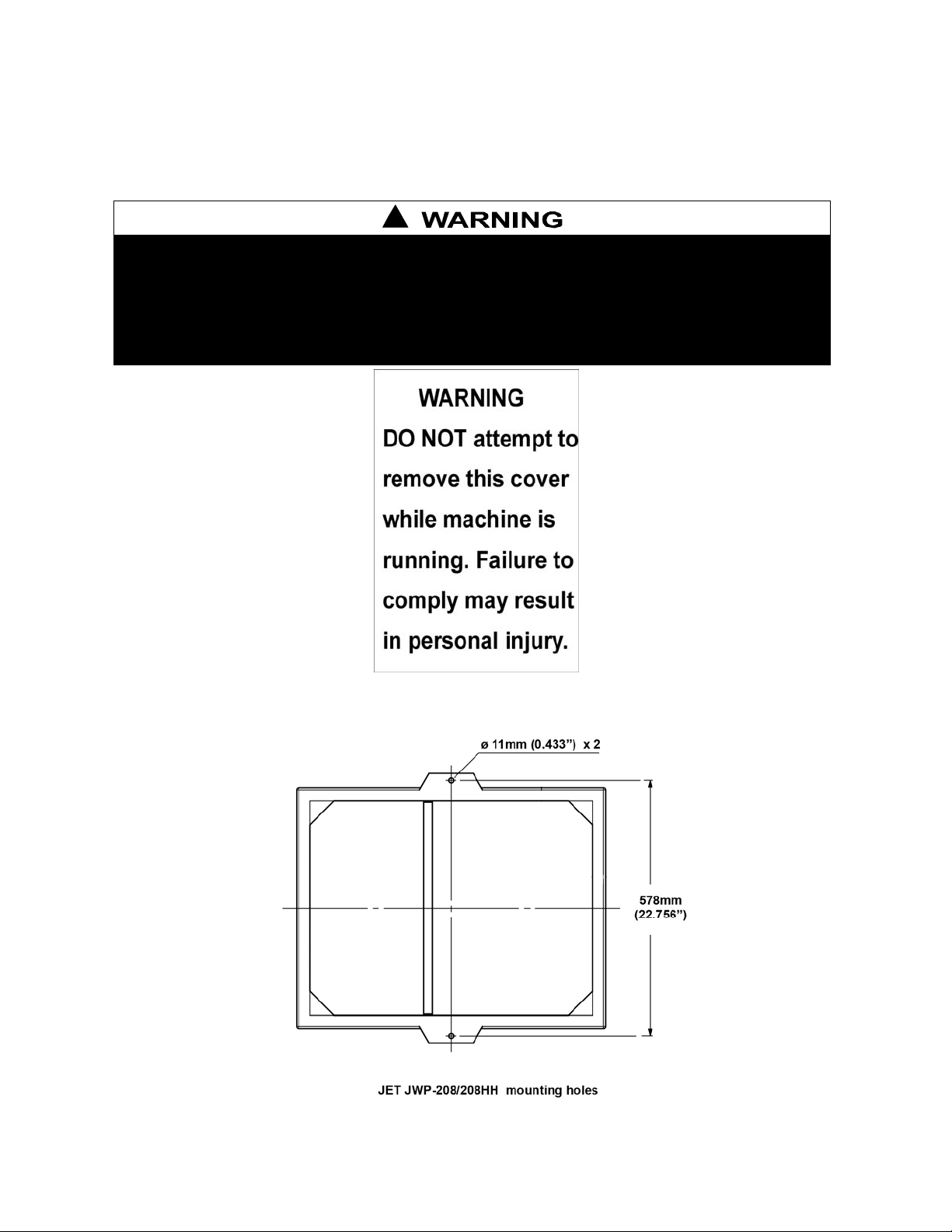
Safety Decals
Familiariz e y our self with the location and content of these decals on your planer.
!
1. Read instruction m anual before operating machine.
2. Do not operate without all gu ards properly installed.
3. Remove or fasten loose articles of clothing such as neckties, etc.
Contain long hair.
4. Remove jewelry such as finger rings, watches, bracelets, etc.
5. Use approved safety glasses and/or face shield to protect eyes, and
use other personal safety equipment as required. Do not wear
gloves.
DO NOT REMOVE OR OBSCURE THIS LABEL
Figure 1
6. Disconnect machine from po wer sou rce before making any
adjustments or cleaning chips away from machine.
7. Keep the floor around machine clean and free from scraps,
sawdust, oil and grease to minimize the danger of slipping.
8. Do not operate this machine while under the influence of alcohol
or drugs.
9. Failure to comply with these warnings may result in serious
personal injury.
Stand Mounting Ho les
Figure 1
5
Page 6
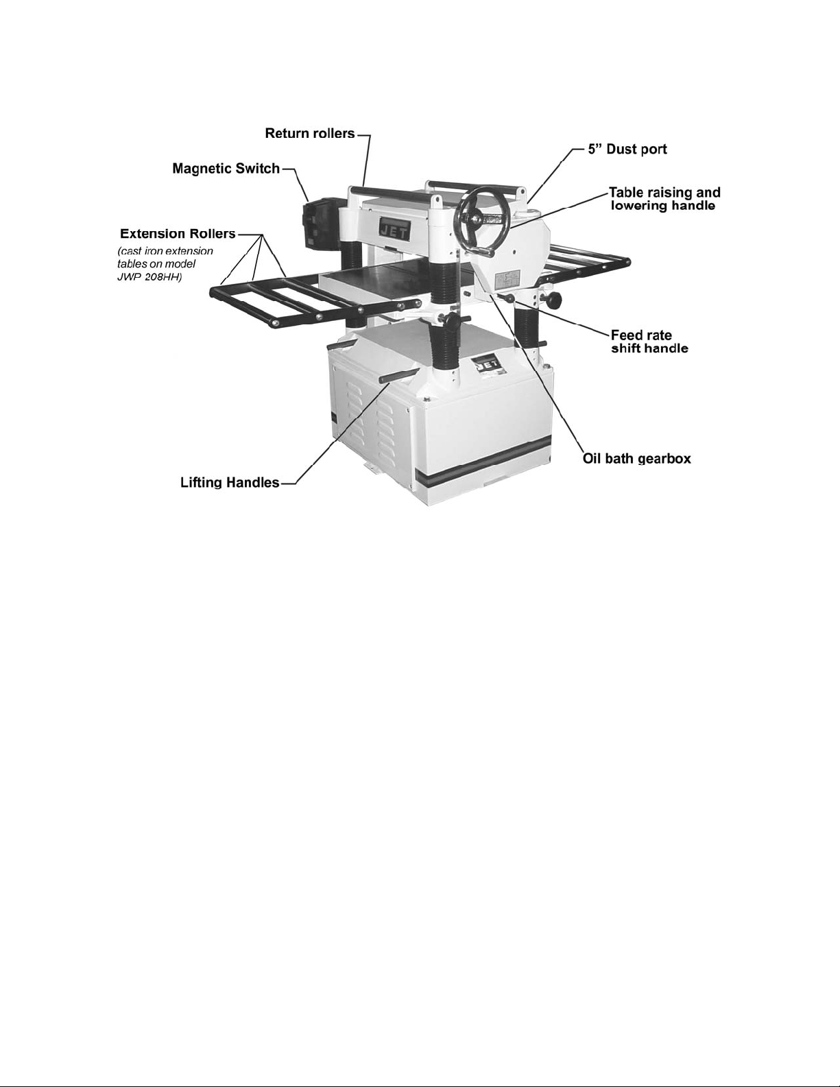
Features
Figure 2
Specifications
Model No. ............................................................................JWP-208 .................................... JWP-208HH
Stock No (3HP, 1Ph, 230V only ) . ........................................... 708528 ..................................................... --
Stock No (5HP, 1Ph, 230V) ............................................................ -- ........................................... 708544
Table Area (D x W/in.) ..................................................... 25-3/4 x 20 ...................................... 25-3/4 x 20
Maximum Planing Width (in.) ......................................................... 20 ................................................... 20
Maximum Planing Thickness (in.) .................................................... 8 ..................................................... 8
Full Width Cutting Depth (in.) ...................................................... 3/32 ................................................ 3/32
Minimum Planing Length (in.) .................................................... 6-3/4 ............................................... 6-3/4
Knives ...................................................................... (4) 20x1x1/8Thk ..................... (92) four-s ided inserts
Cutterhead Speed (RP M ) ......................................................... 5,000 .............................................. 5,000
Cuts per Minute ...................................................................... 20,000 ................................................. n .a.
Cutterhead Diameter (dia/in.) ................................................... 3-3/16 ............................................. 3-3/16
Feed Rate (FPM) ................................................................... 24 & 31 ........................................... 24 & 31
Motor .............................................. TEFC, 3HP,1PH,230V,60Hz,18A .... TEFC , 5HP,1PH,230V,60Hz,23A
Dust Chute Diamet er (di a/in.) ........................................................... 5 ..................................................... 5
Overall Dimensions (L x W x H/in.) ..................... 26 x 36-5/8 x 41-3/8 ........................ 26 x 36-5/8 x 41-3/8
Overall Dimensions (L x W x H/in.) ..................... 26 x 36-5/8 x 41-3/8 ........................ 26 x 36-5/8 x 41-3/8
Net Weight (approx. lbs.) ............................................................. 640 ................................................. 753
*pre-wired 230V
The specificati ons in thi s manual are given as general inf ormation and ar e not binding. JET reserv es the
right to effect, at any time and without prior notice, alterat ions to part s, fittings, and accessory equi pment
deemed necessary f or any reason whatsoever.
6
Page 7
Receiving
Carefully unpack the planer and any loose items
from the wood crate and inspect for damage. Any
damage should be reported immediately to your
distribut or and shipping agent. Bef ore proceeding
further, read your manual thoroughly to f amiliarize
yourself with proper assembly, maintenance and
safety proc edur es.
Remove the screws that hold the planer to the
shipping skid. Remove the protectiv e coating from
the table, bed rolls, feed rolls, cutterhead and
loose items packed with the machine, including
lifting handl es and motor pulley. This coati ng may
be removed with a soft cloth moistened with
Kerosene. Do not use acetone, gasoline or
lacquer thinner for this purpose. Do not use
solvents on plast ic par ts.
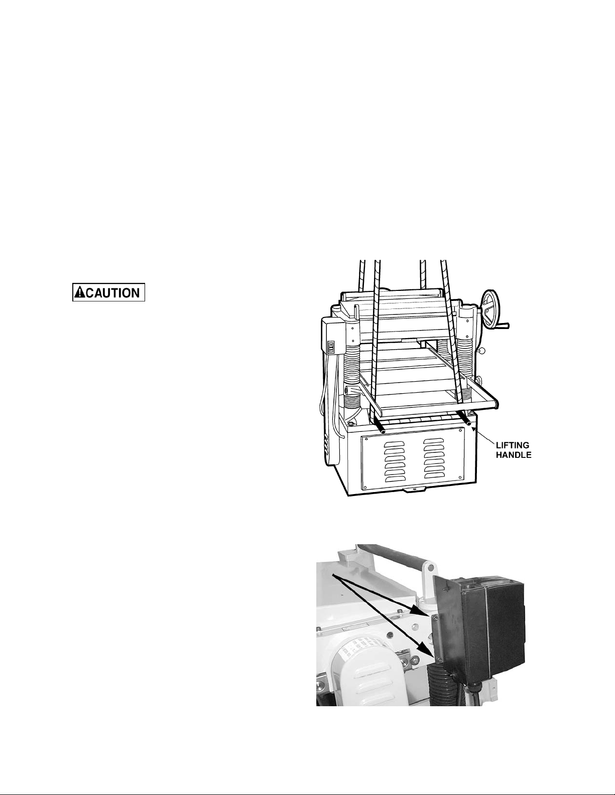
Use care when cleaning the
cutterhead ; th e kni ves are very sharp.
Installation & Assembly
1. There are four lifting handles (Fig. 3) on the
machine. P ull the handles out f or use, push in
when not in use.
2. If a sling or forklif t is used to lif t the mac hine,
be sure to lif t by the handles only . See Fi g. 3.
Make sure machine is kept in level position
while lifting.
3. For best planing performance, locate planer
on a solid, level f oundation and anchor to the
floor with good quality lag screws. Do not
tighten screws completely yet.
4. With machine in position, test table surface
lengthwise and crosswise with machinist’s
level. Place met al shims under low corners.
5. Check that all four corners are supported,
then tighten l ag screws.
6. Re-test level of table surfac e in both directions
and adjust if necessary.
Figure 3
Starter Box
Mount the starter box at the left side of the
machine with two socket head cap screws (Fig. 4).
Figure 4
7
Page 8
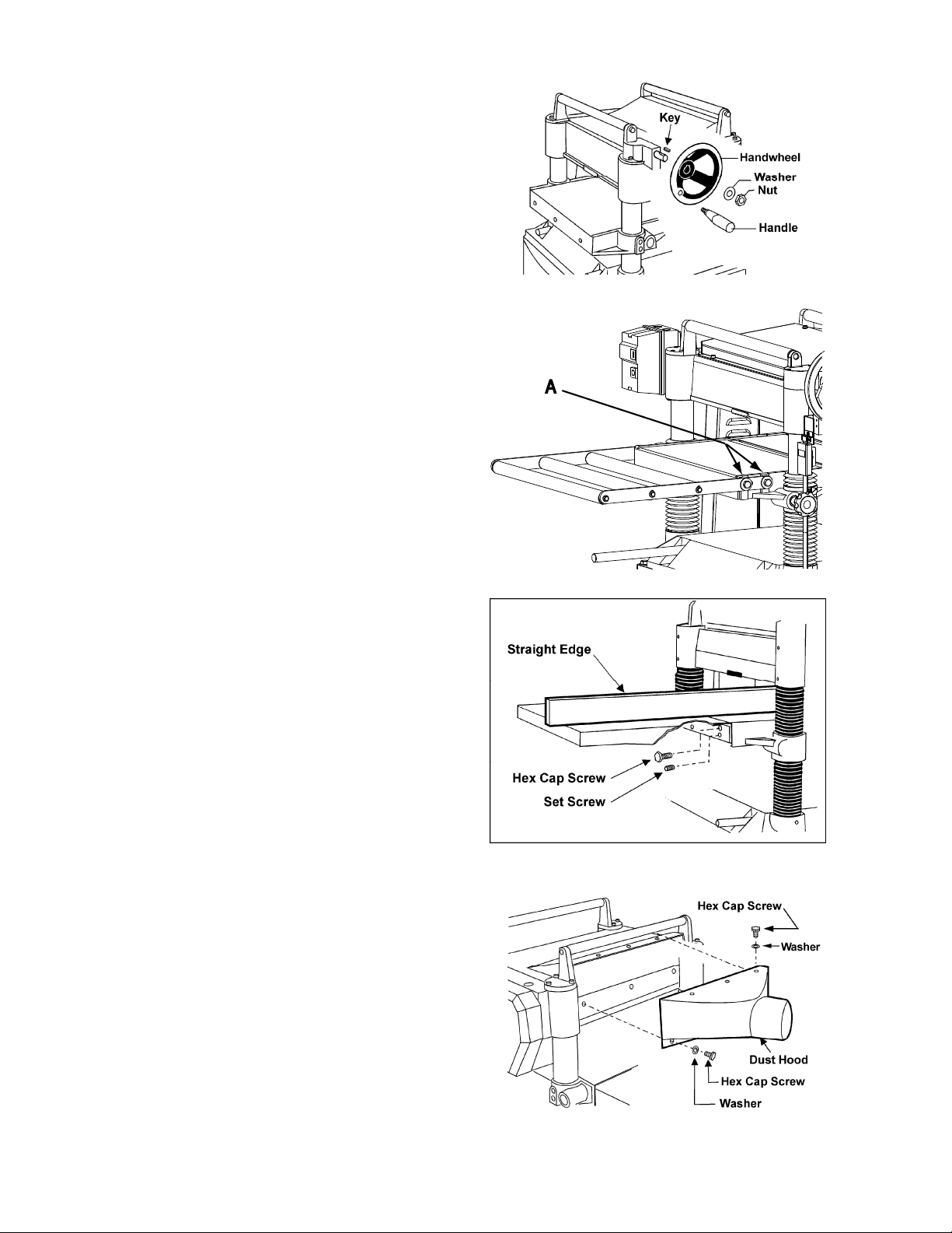
Handwheel
1. Rem ove t he nut and wash er f rom the gearbox
shaft, and pl ace the handwheel onto the shaf t
(Fig. 5), making sure it is oriented so the
handwheel slips over the key.
2. Place flat washer and hex nut on shaft and
tighten with wrench.
3. Mount the handle in the threaded hol e in the
handwheel, and ti ghten with a wrench placed
over the flat on the handle.
Table Extension Rollers (JWP-208 only)
Mount the table extension roller s to the table using
the provided hex cap screws and washers
(A, Fig. 6). The rollers should be adjusted bef ore
operating the planer; see Adjusting Table
Extension Rollers on page 11.
Figure 5
Extension Tables (JWP-208HH only)
1. Mount a cast iron table to the edge of the
main tabl e with t hree M8 x 25 hex c ap screws
(Figure 6a). Do not f ully tighten yet.
2. The ex tension table must be leveled wit h the
main table. Place a straight edge (such as a
jointed board) ac r oss both tables.
3. Insert three socket set screws with a hex
wrench, and scre w them in or out a s needed
until tables are level.
4. Securely tight en the hex cap screws.
5. Mount the second extension table to the
opposite side of the planer table, using the
same procedure.
6.
Dust Collection Hood
The dust collecti on hood (Fi g. 6b) comes standard
with the model JWP-208 planer, and helps
maintain a clean and safe work area. It is
assembled to the planer with the screws and
washers as shown.
Figure 6 - JWP-208 only
Figure 6a - JWP-208HH only
IMPORTANT: Make sure all knives or knife
inserts are ti ght before operating machin e. On
the helical head model, verify tightness of
each insert (re-torque) before using the
machine for the first time.
Figure 6b
8
Page 9
Electrical Connections
El ectrical conn ections must be
made by a qualified electrician in compliance
with all relevant codes. The machine mu st be
properly grounded to help prevent electrical
shock and possible fat al injury.
A power plug is not provided wit h the 208 planer.
You may either connect one or "hard-wire" the
machine dir ectly to your el ectrical panel provided
there is a disconnect near the machine. Consult
the wiring diagrams on pages 32-35 for further
clarific ation of wiring setup.
This machine must be grounded. Grounding
provides a path of least resistance to hel p divert
current away from the operator in case of
electrical malfunction.
Make sure the voltage of your power supply
matches the specifications on the motor plate of
the machine.
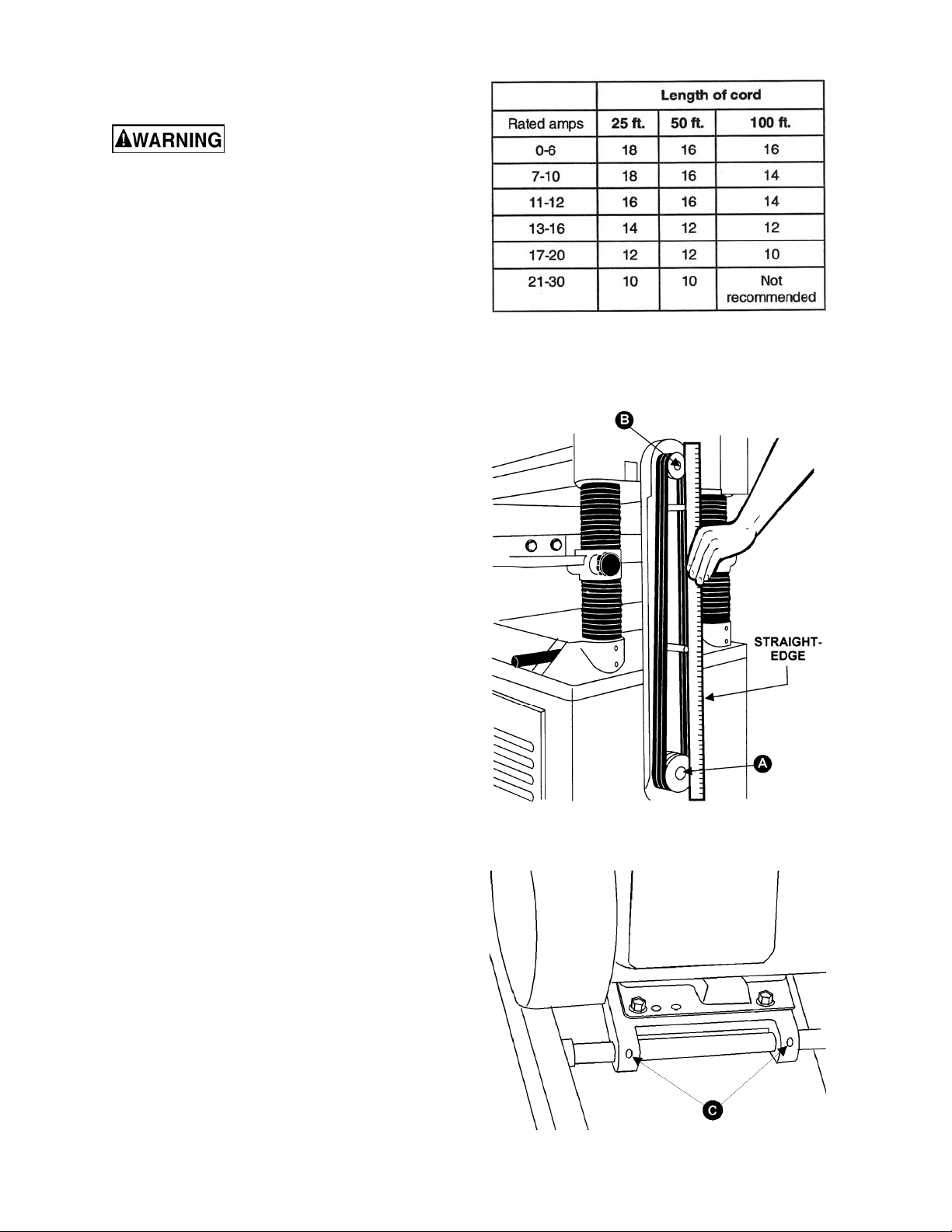
Extens ion Cords
The use of ex tension cords is discouraged; try to
position the machine within reach of the power
source. If an extension cord becomes nece ssary,
make sure the cord rating is suitable for the
amperage list ed on the mac hine's motor pl ate. An
undersized cord will cause a drop in line voltage
resulting in loss of power and overheating.
Figure 7
The chart i n Figure 7 shows the cor rect size cord
to use based on cord l ength and m otor pl ate amp
rating. If in doubt, use the next heavier gauge. The
smaller the gauge number the heavier the cord.
Adjustments
Belt and Pulleys
1. Using a straight edge, align the motor pulley
(A, Fig. 8 ) and cutterhead pulley (B, Fig. 8).
The motor plate can be moved for al ignment
by loosening the set screws (C, Fig. 9) in the
motor plate.
Figure 8
Figure 9
9
Page 10
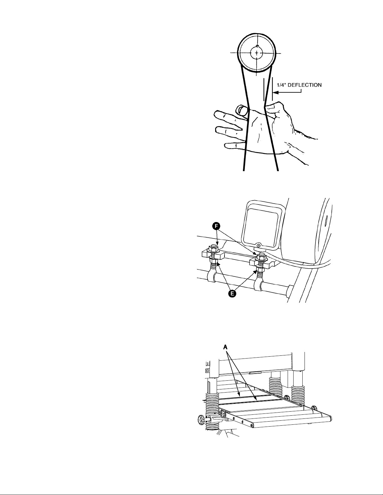
2. Check bel t tensi on. Pr oper tensi on is obtai ned
when there is approx imately 1/ 4” deflection of
the center span of the pulleys using light
finger pressure (Fig. 10).
3. If adjustment of belt tension is necessary,
loosen one pair of hex nuts (E & F, Fig. 11)
and turn the other pair to raise or lower the
motor plate. Re-tighten nuts.
Table Rollers
Figure 10
Figure 11
Overview
Your planer is supplied with two table rollers
(A, Fig. 12) which turn as the stock i s fed int o the
planer, thus reduc ing friction. It is not possible t o
give exact dimensions on the proper height setting
of the table rollers because each type of wood
behaves diff erently.
As a general rule, however, when planing rough
stock, the table rollers should be set at high
position. When planing smooth stock the rollers
should be set at low position.
Figure 12
10
Page 11
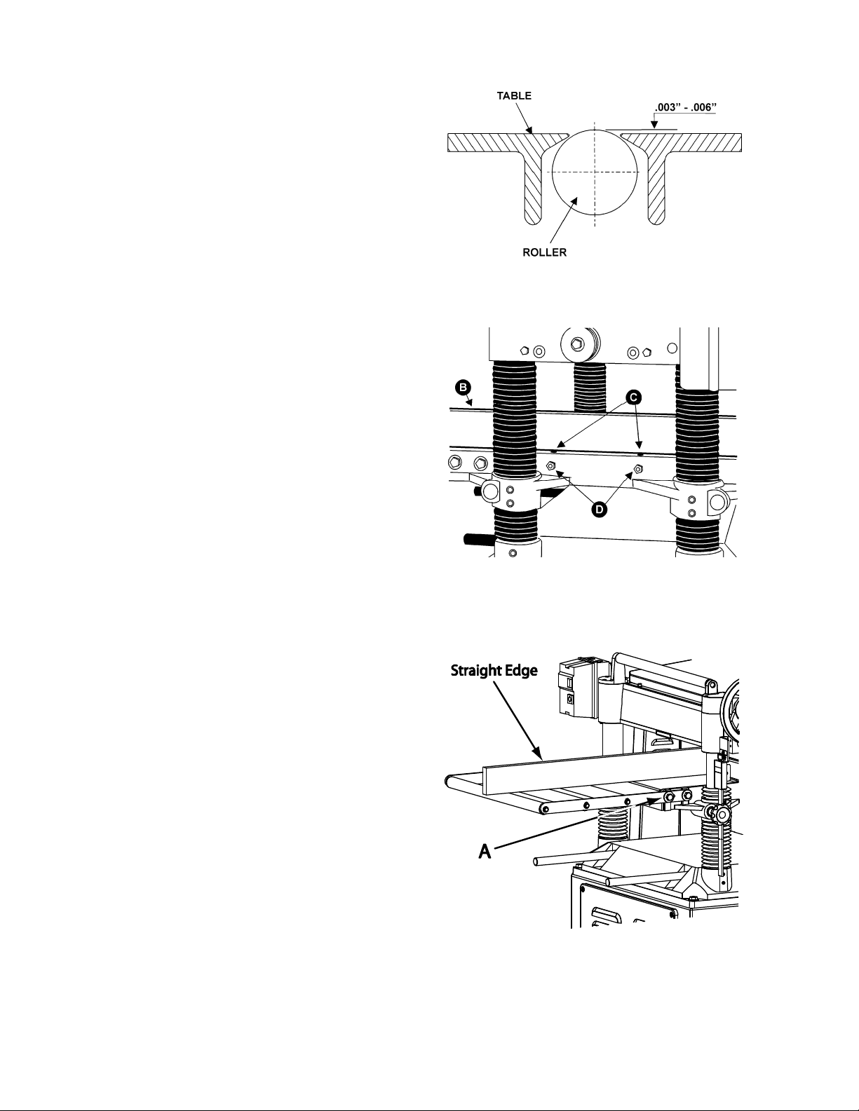
Note: When raising the roller higher above the
table, the available range is from .003” to .006”
See Fig. 13.
The table rollers are factory set for average
planing and are par allel t o the table surfac e. If you
desire to adjust the table rollers higher or lower,
proceed as follows:
1. Disconnect machine from power source.
2. Lay a straight edge (B, Fig. 14) across both
rollers.
3. On one side of the table, loosen the screws
(C, Fig. 14) with a hex wrench, and turn the
eccentri c shafts (D, Fig. 14) to rai se or lower
the rollers.
Figure 13
4. When the proper height is achieved, tighten
screws (C, Fig. 14).
5. Adj ust the r oll ers from t he opposit e side of the
table in the same manner.
Important: Be sure that the height of front and
rear rollers are the same. The table rollers must
always be set parallel to the table.
Adjusting Table Extension Rollers
1. Pl ace a str aight edge ov er t he extensi on rol l er
and the table, as shown in Fig. 15, to make
sure the extensi on roller and table are at the
same height. If necessary, adjust the table
extension roll er s as f ollows:
2. Loosen the screws and washers (A, Fig. 15)
to move the extension roller to the proper
position, then retighten the screws.
3. Adjust both front and rear extension rollers in
the same manner.
Figure 14
Figure 15
11
Page 12

Adjusting Depth of Cut
The cutting depth scale (A, Fig. 16) is a
combination i nch/metric scale with a cutt ing range
from 0 to 8” (204mm). T he distance of upward or
downward movement is controlled by the
handwheel (B, Fig. 16). One revolution of the
handwheel is .059” (1.5mm). Before moving the
table up or down, l oosen the lock nuts (C, Fig. 16).
After obtaining the proper table position, tighten
the lock nuts (C, Fig. 16).
Always tighten the lock nuts
before operating the planer.
Cutterhead Adjustment
Overview
Although your planer was carefully adjusted at t he
factory, it shoul d be checked bef or e being put i nto
operation. A ny inacc uracies due to rough handl i ng
in transit can easily be corrected by following
these directions.
To check the adjustm ents you will need a straight
edge, feeler gauge, and a homemade gauge bloc k
made of hardwood. This gauge block can be
made by following the dimensions shown in
Figure 17.
Figure 16
Knife Adjustmen t (Mod el JWP- 208 on ly)
When checki ng or adjusting the cutterhead k nives,
proceed as follows:
1. Disconnect machine from power source.
2. Remove the six screws (A, Fig. 18) and
remove upper cover (B, Fig. 18).
3. To check and adj ust knives, use the prov ided
knife gauge (F ig. 19 & 20) and check all four
knives. Kniv es should just contact the bot tom
of the center protrusion (D, Fig. 19) of the
knife gauge.
4. If an adjustm ent to one or m ore of t he knives
is necessary, slightly loosen the knife gib
(E, Fig. 19) by turning the six locking screws
(F, Fig. 19) into the gib. Turn the screws just
enough to relieve stress in the cutterhead
without distur bing t he setting of the k nives. Do
this for all f our knives at the same time.
5. With the gauge in place over a knife
(G, Fig. 19) continue to loosen the locking
screws (F, Fig. 19) until the springs
(H, Fig. 19) begi n r aisi ng the knife. When knif e
comes int o contact with the cent er protrusion
(D, Fig. 19) of the gauge, snug up the gib by
lightly backing out the six locking screws (F,
Fig. 19) agai nst the slot.
Figure 17
Figure 18
12
Page 13

NOTE: At this time, only tighten the knife in
the slot just enough to hold knife in position.
6. If additional knives must be reset, repeat
step 5.
7. After all four knives are set with screws just
snug, back out and tighten the six locking
screws (F, Fig. 19 & 20), against the slot
starting with the end screws first, then the
center screws, unt il the knif e is securely held
in the cutterhead. Tighten remaining three
knives in the same manner.
Important: Double check all screws for tightness.
Replacing & Resetting Knives (Model JWP-208 only)
If the knives are removed for sharpening, care
must be exer cise in replaci ng and resetting t hem.
Proceed as follows:
1. Disconnect machine from power source.
2. Remove six screws and upper cover (see
Fig. 18).
3. To remove knife, loosen the gib (E, F ig. 19) by
turning the si x l ocking screws (F , Fi g. 19) into
the gib. Remove gib (E, Fi g. 19), knife (G, Fi g.
16) and spring s (H, F ig. 19). NOTE: The inner
two springs m ay pop out when the knif e and
gib are removed.
Figure 19 – JWP-208 only
4. Remove the remaining three knives in the
same manner.
5. Thoroughl y clean t he knif e slots, gibs, spri ngs
and locking scr ews. Chec k the locking screws;
if the t hreads appear worn or stri pped or if t he
heads are becoming r ounded, replace them.
6. Inspect the cut ting edge of the knives for nicks
or wire edge. Hone the kniv es sl ightly usi ng a
stone, or if the knives are to be sharpened,
maintain a cutti ng angle of 35 degrees.
7. Insert springs, knives and gib into slot of
cutterhead. Back out locking screws just
enough to hold the knife in the cutterhead.
8. Place knife gauge (C, Fig. 19) over knife.
9. While holding down on the knife gauge,
loosen all six locking screws (F) by turning
them into the gi b (E) until cutting edge of knif e
comes into contact with the protrusion (D) of
the gauge. Snug up the gi b by slightly backing
out the six locki ng screws again st the slot.
Note: At this time, only tighten the knife into the
slot just enough t o hold the knife in position.
Figure 20 – JWP-208 only
13
Page 14

10. Replace and reset the other three knives in
the same manner.
11. After all four knives are set with the screws
just snug, back out an d ti ghten the six screws
(F) against the slot starting with the end
screws first and then the center screws until
the knife is securely held in the cutterhead.
Tighten the remaining three knives in the
same manner.
After replacing and checking
knives, CHECK AGAIN carefully. Make certain
the direction of knives is correct and all
twenty-four locking screws are tightened
securely.
Replacing or Rotating Knife Inserts (Model JWP-208HH only)
The knife inserts on the model JWP-208HH are
four-si ded. When dull, simpl y remove each insert,
rotate it 90° for a fresh edge, and re- install it.
Use the provided st ar point screwdriv er to remove
the knife insert screw. See Figure 20a. It is
advisable to r otate all inserts at the sam e time to
maintain consistent cutting. However, if one or
more knife inserts develops a nick, rotate only
those inserts that are affected.
Each knife insert has an etched reference mark so
you can keep track of the rotations.
IMPORTANT: When rem oving or rotating i nserts,
clean saw dust from the scre w, the i nsert, and t he
cutterhead platform. Dust accumulation between
these elements can prevent the insert from
seating properl y, and may affect the quality of the
cut.
Before installing each screw, l ightly coat the screw
threads with mac hine oil and wipe off any excess.
Securely ti ghten each screw which holds the knif e
inserts befor e oper ating the planer!
Make sure all knife insert
screws are tightened securely. Loose inserts
can be propelled at high speed from a rotating
cutterhead , cau sin g inju ry.
Checking Work Table Parallel to Cutterhead
The work tabl e is set parall el to the c utterhead at
the factory and no further adjustment should be
necessary. If your machine is planing a t aper, first
check to see if t he knives are set properly in the
cutterhead. Then check to see if the work tabl e is
set parallel to the cutterhead. Proceed as follows:
Figure 20a – JWP-208HH only
14
Page 15

1. Disconnect machine from power source.
2. Place the gauge block (Figur e 21) on the work
table dir ectl y under the edge of a knife or knife
insert as shown. Make slight cont act with the
knife edge by gentl y raisi ng the table.
3. Move the gauge bloc k to the opposit e end of
the work table. The distance from the work
table to the edge of the knife should be the
same on both ends of the knife.
Adjusting Work Table Parallel to Cutterhead
If the work table i s not parallel to the cutterhead,
perform the adjustm ent procedure as follows:
1. Disconnect the m ac hine from power source.
2. Til t planer on its side to ex pose underside of
base, as shown in Fig. 22.
3. Remove bolt (A, Fig. 22) and loosen bolt (B,
Fig. 22) which will allow you to move the idler
sprocket assembl y (C, Fig. 22) far enough to
release tension on the c hain.
4. Remove chain from the parti cular sprocket on
corner of base that m ust be adjusted.
Turn the sprocket by ha nd to bri ng t hat cor ner
into adjustment with the other three corners.
NOTE: Turning sprocket clockwise will
increase the distance between the working
table and headcasting; counter-clockwise will
decrease the distance. This adjustment is very
sensitive and it should not be necessary to
turn the sprocket m or e than one or two teeth.
5. When adjustments are correct, replace chain
around corner sprock et, slide sprock et (C, Fig.
22) back to re-tension chain, tighten bolt (B,
Fig. 22) and repl ace and tighten bolt (A, Fig.
22).
Know the Transmit ting Rolle r s of Y o ur P la ne r
A – Anti-Kickback Fingers
B – Infeed Roller
C – Chipbreaker
D – Cutterhead
D – Pressure Bar
E – Outfeed Roller
The infeed roller (B, Fig. 23) and outfeed roller
(F, Fig. 23) are those part s of y our planer that feed
the stock whil e it i s being planed. The i nfeed and
outfeed rollers are under spring tension and this
tension must be sufficient to feed the stock
uniformly through the planer without slipping but
should not be so tight that it causes damage to t he
board. The tensi on should be equal at both ends
of each roller.
Figure 21
Figure 22
Figure 23
15
Page 16

Anti-Kickback Fingers
The anti- kickback fingers (A, Fig 23) hel p prevent
kickback of stock. They operate by grav ity and it i s
necessary to inspect them occasionally to make
sure they are f ree of gum and pitch, so that t hey
move independently and operate correctly.
Adjusting Infeed & Outfeed Roller Spring Tension
To adjust the spring tension of the infeed and
outfeed roller s, tur n screws (G & H, Fig. 24) with a
hex wrench. Turn screws on opposite end of
infeed/outfeed rollers in the same manner.
Figure 24
Figure 25
Height of Infeed Roller, Chipbreaker, Pressure Bar & Outfeed Roller
The infeed r oller, chipbreaker, pr essure bar and
outfeed roller are adjusted at the factory. The
infeed roller and the chipbreaker should be set
at 0.004” (0.1mm) below the cutting circle; and
the outfeed roll er should be set at 0. 02” (0.5mm )
below the cutting ci r cl e. See Fig. 25.
If an adjustment to the infeed roller, c hipbreaker,
pressure bar or outf eed roller is necessary, use
the following steps as an example of procedure.
To check and adj ust the out f eed rol l er bel ow the
cutting circl e, proceed as follows:
1. Disconnect machine from power source.
2. Make sure the kniv es are adjusted properl y
as previously explained under “Checking &
Adjusting of Knives.”
3. Place the gauge block (J, Fig. 26) on the
table dir ectl y underneat h the cut ter head (D,
Fig. 26). Usi ng a 0.02” (0.5mm) feeler
gauge (K, Fig. 26) placed on t op of the
gauge block, raise the working table
until the knife just touches the feeler
gauge when the knife is at its lowest
point. Do not move the working table
any further until the outfeed roller is
adjusted.
Figure 26
16
Page 17

4. Mov e t he gauge bl ock (J , F ig. 27) under one end
of the outfeed roll er (F, Fig. 27). The bottom of
the outf eed r oller should just touch the top of the
gauge block. If an adjustment to the outfeed
roller is necessary, loosen the lock nut (L, Fig
27) and turn screw (M, Fig. 27) until the outfeed
roller just touches the gau ge bl ock. Then t i ghten
lock nut (L, Fig. 27).
5. Check and adjust opposite end of the outfeed
roller in the same manner .
Figure 27
4. When the sprockets (B, Fig. 28) are
removed, replace the lower sprocket
which will be assembled on the gear
shaft.
5. Assemble the three sprockets and
chains to the shafts, and tighten the
hex cap screws (E, Fig. 28).
Return Rollers
The two return rollers on the top of the
machine serve as a convenient rest for
stock. They save time and motion for the
operator as the stock is returned to the
infeed side.
Feed Speed Control
Your machine i s equipped wit h a spiral , serr ated
infeed roll er and a sol i d outf eed roll er. When the
feed rollers are engaged, they turn to feed the
stock. The f eed rollers slow autom atically when
the machine is under heavy load f or best planing
in all conditions. The feed rollers are driv en by
chains (A, Fig. 28) and sprockets (B, Fig. 28)
which take power directly from the cutterhead
through the oil bath gear box (C, Fig. 28).
The gear box has two feed speeds. These are
set by pulling out or pushi ng in the shif t lev er (D,
Fig. 28) whil e the machine is running. The f eed
speed range is shown in Fig. 29.
Changing Accessories for Lowest Feed Speed
The lowest feed s peed f or your planer (16.2 fpm
& 20.7 fpm) can be obtained by replacing the
lower (gear shaf t) sprocket and the chain. See
Fig. 29. To change the sprocket and the chain
on your machine, proc eed as follows:
Figure 28
1. Disconnect machine from power source.
2. Remove the three hex cap screws and
washers (E, Fig. 28).
3. Remove the three sprockets (B, Fig. 28)
from the i nfeed roller, outfeed roller and t he
gear shaft at the same time.
Figure 29
17
Page 18

Maintenance
Periodic or regular inspections are required to
ensure that t he machine i s in proper adj ustment,
that all screws are tight, that belts are in good
condition, that dust has not accumulated in the
electric al enclosures, and that there are no worn
or loose elect ri c al c onnec tions.
Lubrication
The bearings on the cutterhead are factory
lubricated and sealed for life – no lubrication
required.
The lubricant in the gearbox must be replaced
every 2,500 hours. Multi-purpose gearbox
lubricant will be sui table.
Buildup of sawdust and other debris can cause
your machine to plane inaccurately. Periodic
cleaning is not onl y r ecommended but mandat ory
for accurat e planing.
Close-fitting parts, such as the cutterhead slot
and gibs, should be cl eaned with a c lot h or brus h
and non-flammable solvent, and freed from
clinging foreign matter.
Remove resin and ot her acc um ulations f rom feed
rollers and table with a soft rag and nonflammabl e solven t.
Periodically check all the chains for proper
tension and adjust acc or dingly if required.
Tip: If a foreign object nicks the knives, i nstead of
throwing them away or trying to grind out the
deep nick, sim ply stagger t he knives i n the head,
moving one knife no more than 1/4" to the right
and another knif e no more than 1/4" to the l eft.
The nick should no l onger be noticeable.
The table shoul d be kept clean and free of rust.
Some users pref er a paste wax coating. A nother
option is talcum powder applied with a
blackboard eraser rubbed in vigorously once a
week; this will fill casting pores and form a
moisture barrier. This method provides a table
top that is sli ck and allows rust rings to be easil y
wiped from t he surface. Important al so is the fac t
that talcum powder will not stain wood or mar
finishes as wax pick up does.
To replace the gearbox lubr icant:
Remove the dr ain plug (A, Fig. 30), and filler cap
(B, Fig. 30). Drain dirty oil thoroughly.
Tighten the drain plug (A, Fig. 30).
Fill with cl ean lubricant through hole (B , Fi g.
30).
Tighten fill er cap ( B, Fig. 30).
Figure 30
18
Page 19

[The item numbers on this chart are referenced with the accompanying illustrations.]
t
No. Position Interval Suitable Types of Lubrican
1 Drive Chain Frequently Grease 30
2 Gear Box When operated more than
2,500 hours
3 Return Rollers Frequently SAE-30 32
4 Worm Gear Frequently Grease 33
5 Lead Screw Frequently Grease 33
6 Column Frequently Clean and SAE-30 33
7 Table Chain Frequently Grease 34
8 Feed Rollers Frequently SAE-30 35
70 to 90 weight gear oil 30
2
Fig. No.
Figure. 31
Figure 32
Figure 34
Figure 33
Figure 35
19
Page 20

Troubleshooting
Operating Problems
Problem Possible Cause Solution
Snipe.
(Snipe cannot be
eliminat ed, but can
be minimized so
as to become
negligible.)
Fuzzy Grain Planing wood with a high
Torn Grain Too heavy a cut.
Rough/Raised
Grain
Table rollers not set pr oper ly.
Inadequate support of long
boards.
Uneven feed roller pr essure
front to back.
Dull Knives.
Lumber not butt er properly.
moisture cont ent.
Dull knives.
Knives cutti ng against grain.
Dull knives.
Dull knives.
Too heavy a cut.
Moisture cont ent too high.
Adjust rollers to proper height.
Support long boar ds with ex tension rollers.
Adjust feed roller tension.
Sharpen knives.
Butt end to end each pi ec e of stock as they
pass through.
Remove high moisture c ontent from wood by
drying.
Sharpen or replac e.
Adjust proper dept h of cut.
Cut along the grai n.
Sharpen knives.
Sharpen knives.
Adjust proper dept h.
Remove high moisture c ontent from wood by
drying.
Rounded, glossy
surface
Poor feeding of
lumber
Dull knives.
Feed speed too slow.
Cutting dept h too shal low.
Inadequate f eed r oller
pressure.
Planer bed rough or dr y.
Transmission v-belt slipping.
Surface of feed rollers too
smooth.
Sharpen or replac e k niv es.
Increase speed.
Increase depth.
Adjust feed roller tension. If proper tension
cannot be achiev ed, replace feed rollers.
Clean pitch and resi due, and wax planer table.
Tighten transmission v-belt.
Lightly roughen t he feed roller surface with
sandpaper.
Mechanical and Electrical Problems
Problem Possible Cause Solution
Uneven depth of
cut side to side.
Board thickness
does not match
depth of cut scale.
Knife projection.
Cutterhead not level with bed.
Depth of cut scale incor r ec t. Adjust depth of cut scale.
Adjust knife pr ojec tion.
Level bed.
20
Page 21

Problem Possible Cause Solution
Chain jumping. Inadequate tension.
Sprockets misaligned.
Sprockets worn.
Machine will not
start/restart or
repeatedly trips
circuit breaker or
blo ws fuses.
No incoming power.
Overload automatic reset has
not reset.
Planer frequently trips.
Building circuit breaker trips
of fuse blows.
Adjust chai n tension.
Align sprockets.
Replace sprockets.
Verify unit is connected to power.
When planer overl oads on the ci r c uit breaker
built into th e motor s ta rte r , i t ta ke s time for the
machine to cool down befor e r estar t. Allow
unit to adequately cool before attempting
restart. If pr oblem persists, check amp setting
on the motor starter insi de the electrical box.
One cause of overl oading trips which are not
electric al in nature is too heavy a cut. If too
deep a cut is not the problem, t hen c hec k the
amp setting on the overload relays. Match the
full load amps on the motor as noted on the
motor plate. If amp setti ng is cor r ec t then there
is probably a loose elec trical lead. Check amp
setting on mot or start er .
Verify that planer is on a circuit of correct size.
If circuit siz e is corr ect, there is probably a
loose electri c al lead. Check amp setting on
motor starter.
Loose electri c al c onnec tions.
Motor starter failure.
Motor starter failure.
Motor failure.
Go through all the elec trical connections on
the planer including motor connections,
verifyi ng the ti ghtness of each. Look for any
signs of electri c al ar ci ng whic h is a sure
indicator of loose connections or circuit
overload.
Examine motor star ter for burned or failed
components. If dam age is found, replace
motor starter . If m otor st ar ter looks okay but is
still suspect, y ou have two options: have a
qualified elec trician test the motor starter for
function, or pur c hase a new starter and
establish if t hat was the problem on changeout.
If you have access to a voltmeter, you can
separate a starter failure from a motor failure
by first, verifying incoming voltage at 220 +/20 and second, checking the voltage between
starter and motor at 220 +/- 20.
If incoming voltage is incorrect, you have a
power supply problem .
If voltage between starter and motor is correct,
you have a motor problem .
If electrical motor is suspect, you have two
options: Hav e a qualified electrician test the
motor for function or remove the motor and
take it to a qualifi ed el ec tric motor repair shop
and have it tested.
21
Page 22

Problem Possible Cause Solution
Miswiring of the unit.
On/off switch failure.
Double check to confi rm all electrical
connections are cor r ec t and tight. Refer to
wiring diagr am s on pages 32-35 to mak e any
needed corrections.
If the on/off switch is suspect you have two
options: Hav e a qualified electrician test the
switch for function, or purchase a new on/off
switch and establish if that was the problem on
changeout.
Optional Accessories
Stock No Description
708119 ........... Mobile Base
708520 ........... Digital Read-out Retrofit Kit
708583 ........... Low Speed Gear K it
708808 ........... Knives, Single Sided (set of 4) – model JWP-208 only
1791212 ......... Knife Inserts (set of 10) – model JWP-208HH only
Ordering Replacement Parts
To order parts or reac h our service departm ent, call 1-800-274-6848, Monday throug h Friday (see our
website for business hours, www.jettools.com). Having the Model Number and Serial Number of your
machine available when you call will allow us to serve you quickly and accurately.
Parts
Head Assembly – Parts List
Index Part No. Description Size Qty
1 ............... JWP208-001 ............Head Casting......................................................................................... 1
2 ............... TS-1525021 .............Set Screw ...........................................................M10 x 12 .................... 8
3 ............... JWP208-003 ............Cutterhead* ........................................................................................... 1
4 ............... 6292620...................Spring* .................................................................................................. 8
5 ............... 708808 ....................Knife* .................................................................................................... 4
6 ............... JWP208-006 ............Knife Gib* .............................................................................................. 4
7 ............... 6292623...................Hex Cap Bolt* .....................................................M8 x 10 .................... 24
8 ............... JWP208-008 ............Knife Gauge Bar .................................................................................... 1
9 ............... JWP208-009 ............Knife Gauge .......................................................................................... 2
10 ............. JWP208-010 ............Washer...............................................................3/8 .............................. 2
11 ............. JWP208-011 ............Nut .....................................................................M 10 ............................ 2
12 ............. BB-6206ZZ ..............Ball Bearing ........................................................6206ZZ....................... 1
13 ............. JWP208-013 ............Key.....................................................................8 x 8 x 36 ................... 1
14 ............. 6292630...................Pulley .................................................................................................... 1
15 ............. 6292631...................Washer .................................................................................................. 2
16 ............. TS-1523071 .............Set Screw ...........................................................M6 x 25 ...................... 2
17 ............. JWP208-017 ............Motor Pulley .......................................................................................... 1
18 ............. JWP208-018 ............Infeed Roller .......................................................................................... 1
19 ............. JWP208-019 ............Bushing ................................................................................................. 4
20 ............. JWP208-020 ............Sprin g.................................................................................................... 4
21 ............. JWP208-021 ............Screw .................................................................M22 x 20 .................... 4
22 ............. JWP208-022 ............Plate ...................................................................................................... 4
23 ............. TS-1490031 .............He x Cap S cr e w ..................................................M8 x 20 ...................... 8
24 ............. JWP208-024A ..........Jack Screw* .......................................................................................... 8
* Index # 3, 4, 5, 6, 7 and 24 are used only on the straight cutterhead, model JWP-208
22
Page 23

Head Assembly – Parts List
Index Part No. Description Size Qty
25 ............. TS-1540041 .............Hex Nut ..............................................................M6 .............................. 8
26 ............. JWP208-026A ..........Key.....................................................................5 x 5 x 24 ................... 2
27 ............. 6292643...................Sprocket ................................................................................................ 1
28 ............. TS-1550041 .............Washer...............................................................M6 .............................. 2
29 ............. JWP208-029A ..........Hex Wash er Head Screw....................................M6 x 16 ...................... 5
30 ............. JWP208-030 ............Outfeed Roller ....................................................................................... 1
31 ............. 6292647...................Sprocket ................................................................................................ 1
32 ............. JWP208-032 ............Locking Bolt ........................................................................................... 1
33 ............. JWP208-033 ............Retaining Ring ....................................................................................... 1
34 ............. JWP208-034 ............Chip Breaker ......................................................................................... 1
35 ............. TS-1540081 .............Nu t .....................................................................M12 ............................ 2
36 ............. JWP208-036 ............Plate S p rin g s ......................................................................................... 3
37 ............. JWP208-037 ............Washer...............................................................1/4 ............................ 12
38 ............. JWP208-038A ..........Hex Wash er Head Screw....................................M6 x 12 .................... 14
39 ............. JWP208-039 ............Sha ft ..................................................................................................... 1
40 ............. JWP208-040 ............Bracket .................................................................................................. 2
41 ............. JWP208-041 ............Pressure Plate ....................................................................................... 1
42 ............. TS-2361081 .............Lo ck Was h e r ......................................................M8 .............................. 2
43 ............. JWP208-043 ............Sha ft ..................................................................................................... 1
44 ............. TS-1523051 .............Set Screw ...........................................................M6 x 16 ...................... 9
45 ............. TS-1523061 .............Set Screw ...........................................................M6 x 20 ...................... 2
46 ............. JWP208-046 ............Plate S p rin g ........................................................................................... 3
47 ............. JWP208-047 ............Chip Deflector Plate ............................................................................... 1
48 ............. 6292664...................Anti-Kickback Finger ............................................................................ 87
49 ............. 6292665...................Collar .................................................................................................. 88
50 ............. JWP208-050 ............Sha ft ..................................................................................................... 1
51 ............. JWP208-051 ............Retaining Ring ....................................................................................... 2
52 ............. 6292668...................Cut Limit Plate ....................................................................................... 1
53 ............. JWP208-053A ..........Fl at Head Machine Screw ...................................M5 x 8 ........................ 2
54 ............. JWP
55 ............. JWP208-055 ............Gas ket................................................................................................... 1
56 ............. JWP208-056 ............Collector Tube ....................................................................................... 1
57 ............. JWP208-057 ............Roller Stand .......................................................................................... 3
58 ............. JWP208-058 ............Roller .................................................................................................... 3
59 ............. TS-1503041 .............Socket Head Cap Screw .....................................M6 x 16 ...................... 9
60 ............. JWP208-060 ............Wor m Gea r Bo x ..................................................................................... 1
61 ............. TS-1503111 .............Socket Head Cap Screw .....................................M6 x 50 ...................... 3
62 ............. JWP208-062 ............Wor m .................................................................................................... 1
63 ............. BB-6201Z ................Ball Bearing ........................................................................................... 1
64 ............. JWP208-064 ............Retaining Ring ....................................................6201Z ......................... 1
65 ............. JWP208-065 ............Key.....................................................................4 x 4 x 10 ................... 1
66 ............. JWP208-066 ............Hand Wheel .......................................................................................... 1
67 ............. JWP208-067 ............Washer...............................................................1/2 .............................. 1
68 ............. 6292684...................Handle................................................................................................... 1
69 ............. JWP208-069 ............Scale ..................................................................................................... 1
70 ............. JWP208-070 ............Machine Screw ...................................................M5 x 10 ...................... 2
71 ............. JWP208-071 ............Pointe r................................................................................................... 1
72 ............. 6292814...................Special Washer ..................................................M6 .............................. 3
73 ............. JWP208-073 ............Co ver .................................................................................................... 1
74 ............. JWP208-074 ............Spring Pin...........................................................6 x 20 ......................... 1
75 ............. JWP208-075 ............Safe ty P late ........................................................................................... 1
76 ............. JWP208-076 ............Machine Screw ...................................................M6 x 8 ........................ 4
77 ............. JWP208-077 ............Safety Latch .......................................................................................... 1
78 ............. TS-1504081 .............Socket Head Cap Screw .....................................M8 x 40 ...................... 1
79 ............. JWP208-079 ............Pul ley Gu a rd ......................................................................................... 1
80 ............. 6292696...................Bolt........................................................................................................ 2
208-054 ............Upper Cover .......................................................................................... 1
23
Page 24

Head Assembly – Parts List
Index Part No. Description Size Qty
81 ............. TS-0680041 .............Washer...............................................................5/16 ............................ 2
82 ............. TS-0561021 .............Nu t .....................................................................5/16-18 ....................... 2
83 ............. VB-M60....................V-Belt .................................................................................................... 3
84 ............. JWP208-084 ............Pulley Cover .......................................................................................... 1
85 ............. 6292710...................Knob ..................................................................5/16 ............................ 2
86 ............. JWP208-086A ..........Switch Mounting Plate ........................................................................... 1
87 ............. JWP208-087F ..........Magnetic Switch (JWP-208 only) ........................3HP, 1Ph, 230V .......... 1
................. JWP208-087FC .......Contactor (JWP-208 only, not shown) .................3HP, 1Ph, 230V .......... 1
................. JWP208-087FO .......Overload (JWP-208 only, not shown) ..................3HP, 1Ph, 230V .......... 1
................. JWP208HH-087A .....Magnetic Switch (JWP - 208HH only ) ...................5HP, 1Ph, 230V .......... 1
................. 209-5016BC.............Contactor (JWP-208HH only, not shown) ............5HP, 1Ph, 230V .......... 1
................. 209-5016CO ............Overload (JWP-208HH only, not shown) .............5HP, 1Ph, 230V .......... 1
................. JWP208HH-087B .....Magnetic Switch .................................................5HP, 3Ph, 230V .......... 1
................. 209-5016DC ............Contactor (not shown) ........................................5HP, 3Ph, 230V .......... 1
................. JWP208HH-087BO ..Overload (not shown) .........................................5HP, 3Ph, 230V .......... 1
................. JWP208HH-087C ....Magnetic Switch .................................................5HP, 3Ph, 460V .......... 1
................. 209-5016EC.............Contactor (not shown) ........................................5HP, 3Ph, 460V .......... 1
................. 209-5016EO ............Overload (not shown) .........................................5HP, 3Ph, 460V .......... 1
88 ............. TS-1540031 .............Nu t .....................................................................M5 .............................. 2
89 ............. TS-1482021 .............He x Cap S cr e w ..................................................M6 x 12 .................... 10
91 ............. JWP208-091 ............Cha in .................................................................................................... 1
92 ............. JWP208-092 ............Relie f Bushing ....................................................................................... 2
................. JWP208HH-092 .......Relief Bushing (for 5HP, 1PH, 230V only) .............................................. 2
93 ............. JWP208-093 ............Power Cord ........................................................................................... 1
................. JWP208HH-093 .......Power Cord (for 5HP, 1PH, 230V only) .................................................. 1
94 ............. JWP208-094 ............Tooth Washe r ........................................................................................ 4
95 ............. TS-1503021 .............Socket Head Cap Screw .....................................M6 x 10 .................... 12
96 ............. TS-1524011 .............Set Screw ...........................................................M8 x 8 ........................ 1
98 ............. JWP208-098 ............Collar .................................................................................................... 1
99 ............. 6292714...................Shaft ..................................................................................................... 1
100 ........... PA-C59 ....................Idler Pulley ............................................................................................ 1
101 ........... PA-C58 ....................Bracket .................................................................................................. 1
................. JWP208-106 ............Chain Tensioning Assy .......................................................................... 1
102 ........... PA-C59 ....................Shaft ..................................................................................................... 1
103 ........... PA-C60 ....................Hanger .................................................................................................. 1
104 ........... PA-C61 ....................Spring.................................................................................................... 1
105 ........... PA-C62 ....................Collar .................................................................................................... 1
106 ........... TS-1534042 .............Pan Head Screw ................................................M6X1 2........................ 1
107 ........... TS-1503021 .............Socket Head Cap Screw .....................................M6x10 ........................ 2
108 ........... JWP208-108 ............Hex Head Screw ................................................M8 x18 ........................ 4
................. MS-SA20 -24V ..........M agnetic Contactor f or 3HP Motor ( not shown) ...................................... 1
................. MS-SA20 -24VA........Magnetic Contactor for 5HP, 3PH Motor ( not shown) ............................. 1
................. MS-208HH-24V........Magnetic Contactor for 5HP, 1PH Motor ( not shown) ............................. 1
................. JWP208-087DTR .....Thermal Relay for 3HP Motor (not shown) ............................................. 1
................. JWP208-087ETR .....Thermal Relay for 5HP, 3PH Motor (not shown) ..................................... 1
................. JWP208HH-108TR ..Thermal Relay for 5HP, 1PH Motor (not shown) ..................................... 1
................. PG-M02 ...................JET Plaque ............................................................................................ 1
................. 6012192...................Warning Label (not shown) .................................................................... 1
................. 6292819
................. 6292820...................Guard Label (not shown) ....................................................................... 1
................. 1791224...................Helical Cutterhead Assembly (index #109 thru #111)** .......................... 1
109 ........... JWP208HH-109 .......Helical Cutterhead** .............................................................................. 1
110 ........... 1791212...................Knife Insert (sold in set of 10)** ..................................................... 92 total
111 ........... JWP208HH-111 .......Knife Insert Screw** ............................................#10-32 x 1/2” ............ 92
112 ........... JJ6HH-113 ...............Star Point Screwdriver (not shown)** ..................................................... 2
** Index # 109 thru 112 are used only on the helical cutterhead, model JWP-208HH
...................Lubrication Label (not shown) ................................................................ 1
24
Page 25

Head Assembly – Exploded View
25
Page 26

Table and Roller – Parts and Assembly
Index Part No. Description Size Qty
1 ............... JWP208HH-201 .......Middle Table .......................................................................................... 1
2 ............... 6292722...................Roller .................................................................................................... 2
3 ............... BB-6201ZZ ..............Ball Bearing ........................................................6201ZZ....................... 4
4 ............... 6292724...................Eccentric Shaft ...................................................................................... 1
5 ............... TS-1523041 .............Set Screw ...........................................................M6x12 ........................ 4
6 ............... 6292725...................Lock Bar ................................................................................................ 2
7 ............... 6292726...................Lock Bolt ............................................................................................... 2
8 ............... 6292727...................Lock Bushing (no thread) ....................................................................... 2
9 ............... 6292728...................Knob ..................................................................................................... 2
10 ............. TS-1504041 .............Socket Head Cap Screw .....................................M8x20 ........................ 8
11 ............. 6292730...................Roller Frame* ........................................................................................ 4
12 ............. 6292731...................Roller* ................................................................................................... 6
13 ............. TS-1491031 .............Hex Cap Screw* .................................................M10x25 ...................... 8
14 ............. TS-0680041 .............Wash er* .............................................................3/8” ............................. 8
15 ............. 6292808...................Shaft* .................................................................................................... 6
16 ............. 6292809...................Bushing* .............................................................................................. 12
17 ............. TS-1482021 .............Hex Head Screw* ...............................................M6x12 ...................... 12
18 ............. TS-1550041 .............Fla t Washer * ......................................................M6 ............................ 12
19 ............. JWP208HH-219 .......Extension Table** .................................................................................. 2
20 ............. TS-1524051 .............Socket Set Screw** ............................................M8x20 ........................ 6
21 ............. TS-1490041 .............He x Cap Screw** ................................................M8x25 ........................ 6
* Index #11 thru 18 are used only on the model JWP-208.
** Index #19, 20 and 21 are used only on the model JWP-208HH.
26
Page 27

Stand and Motor – Parts and Assembly
Index Part No. Description Size Qty
1 ............... JWP208-401 ............Stand .................................................................................................... 1
2 ............... JWP208-402 ............Cover .................................................................................................... 2
3 ............... TS-2286201 .............Flat Head Machine Screw ...................................M6 x 20 ...................... 8
4 ............... 6292796...................Bar ........................................................................................................ 2
5 ............... JWP208-405 ............Motor Mount .......................................................................................... 1
6 ............... TS-1524011 .............Set Screw ...........................................................M8 x 8 ........................ 4
7 ............... JWP208-407 ............Collar .................................................................................................... 1
8 ............... JWP208-408 ............Adjust Bolt ............................................................................................. 2
9 ............... TS-1540081 .............Nut .....................................................................M12 ............................ 8
10 ............. TS-0680061 .............Washer...............................................................1/2 .............................. 4
11 ............. TS-1490041 .............He x Cap S cr e w ..................................................M8 x 35 ...................... 4
12 ............. TS-0680031 .............Washer...............................................................5/16 ............................ 4
13 ............. TS-1540061 .............Nu t .....................................................................M8 .............................. 4
14 ............. JWP208-414 ............Motor (3HP, 1Ph, 230V) ........................................................................ 1
................. 209-5023 .................Motor (5HP, 1Ph, 230V) ........................................................................ 1
................. JWP208-414A ..........Motor (5HP, 3Ph, 230/460V) .................................................................. 1
15 ............. JWP208-415 ............Key........................................................................................................ 1
16 ............. TS-1492051 .............He x Cap S cr e w ..................................................M12 x 50 .................... 4
17 ............. JWP208-417 ............Power Cord ........................................................................................... 1
................. JWP208HH-417 .......Power Cord (for 5HP, 1PH, 230V only) .................................................. 1
18 ............. JWP208-418 ............Strain Relief ........................................................................................... 1
................. JWP208HH-418 .......Strain Relief (for 5HP, 1PH, 230V only).................................................. 1
19 ............. TS-0680031 .............Washer...............................................................5/16 ............................ 4
20 ............. STRIPE-1-3/4 ..........JET Stripe (not shown) .......................................1-3/4 w ................ per ft.
27
Page 28

Base and Column – Parts List
Index Part No. Description Size Qty
1 ............... JWP208-301 ............Base ...................................................................................................... 1
2 ............... TS-1525021 .............Set Screw ...........................................................M10 x 12 .................... 8
3 ............... JWP208-303 ............Column.................................................................................................. 3
4 ............... JWP208-304 ............Column.................................................................................................. 1
5 ............... JWP208-305 ............Lead Screw ........................................................................................... 3
6 ............... JWP208-306 ............Lead Screw ........................................................................................... 1
7 ............... JWP208-307 ............Nut ........................................................................................................ 4
8 ............... JWP208-308 ............Bushing ................................................................................................. 1
9 ............... JWP208-309 ............Retaining Ring ....................................................................................... 1
10 ............. JWP208-310 ............Key.....................................................................4 x 4 x 10 ................... 1
11 ............. JWP208-311 ............Gear ...................................................................24T............................. 1
12 ............. JWP208-312 ............Retaining Ring ....................................................................................... 1
13 ............. BB-6202ZZ ..............Ball Bearing ........................................................6202ZZ....................... 4
14 ............. JWP208-314 ............Retaining Ring ....................................................................................... 4
15 ............. JWP208-315 ............Key.....................................................................5 x 5 x 16 ................... 4
16 ............. JWP208-316 ............Sprocket .............................................................10T............................. 4
17 ............. JWP208-317 ............Washer...............................................................3/8 .............................. 4
18 ............. JWP208-318 ............Nut .....................................................................M 10 ............................ 4
19 ............. JWP208-319 ............Wash er.................................................................................................. 2
20 ............. TS-1490041 .............He x Cap S cr e w ..................................................M8 x 25 ...................... 2
21 ............. 6292749...................Idler Bra ck e t .......................................................................................... 1
22 ............. JWP208-322 ............Sha ft ..................................................................................................... 1
23 ............. 6292751...................Sprocket .............................................................10T............................. 1
24 ............. JWP208-324 ............Retaining Ring ....................................................STW-15 ...................... 1
25 ............. JWP208-325 ............Cha in .................................................................................................... 1
26 ............. JWP208-326 ............Carry Handle ......................................................................................... 4
27 ............. JWP208-327 ............Retaining Ring ....................................................ETW-19 ...................... 4
28 ............. JWP208-328
29 ............. TS-1533032 .............Pan Head Screw ................................................M5 x 10 .................... 32
30 ............. JWP208-330 ............Expansion Band .................................................................................... 8
............Pipe Band............................................................................................ 16
28
Page 29

Base and Column – Assembly
29
Page 30

Gearbox – Parts List
Index Part No. Description Size Qty
1 ............... JWP208-501 ............Gear Box ............................................................................................... 1
2 ............... OS-28408 ................Oil Seal ................................................................................................. 1
3 ............... BB-6204ZZ ..............Ball Bearing ........................................................6204ZZ....................... 1
4 ............... 6292762...................Gear ...................................................................16T............................. 1
5 ............... TS-1503061 .............Socket Head Cap Screw .....................................M6 x 25 ...................... 1
6 ............... TS-1550041 .............Washer...............................................................M6 .............................. 2
7 ............... TS-1503041 .............Socket Head Cap Screw .....................................M6 x 16 ...................... 1
8 ............... BB-6201...................Ball Bearing ........................................................6201 ........................... 2
9 ............... 6292766...................Gear ...................................................................47T............................. 1
10 ............. 6292767...................Shaft ..................................................................1 8 T............................. 1
11 ............. JWP208-511 ............Key.....................................................................5 x 5 x 12 ................... 1
12 ............. 6292769...................Gear ...................................................................71T............................. 1
13 ............. JWP208-513 ............Key.....................................................................5 x 5 x 10 ................... 1
14 ............. JWP15H-314 ...........Sh a ft ..................................................................1 8 T/2 2 T ...................... 1
17 ............. JWP208-517 ............Gear ...................................................................96T............................. 1
18 ............. JWP208-518 ............Gear ...................................................................92T............................. 1
19 ............. TS-1503021 .............Socket Head Cap Screw .....................................M6 x 10 ...................... 3
20 ............. JWP208-520 ............Key.....................................................................6 x 6 x 40 ................... 1
21 ............. JWP208-521 ............Ball ........................................................................................................ 1
22 ............. 6292776...................Spring .................................................................................................... 1
23 ............. 6292777...................Shaft ..................................................................................................... 1
24 ............. OS-25476 ................Oil Seal ................................................................................................. 1
25 ............. 6292791...................Sprocket .............................................................18T............................. 1
................. 6292779...................Sprocket .............................................................12T............................. 1
27 ............. 6292792...................Chain…………………………………………..06BX52 (for 6292791) ......... 1
................. 6292780
28 ............. TS-1482031 .............He x Cap S cr e w ..................................................M6 x 16 ...................... 1
29 ............. 6292781...................Clutch .................................................................................................... 1
30 ............. 6292782...................Handle................................................................................................... 1
32 ............. JWP208-038A ..........Hex Wash er Head Screw ...................................M6 x 12 ...................... 1
33 ............. JWP208-533 ............Oil Ring ................................................................................................. 1
34 ............. 6292784...................Knob ..................................................................................................... 1
35 ............. 6292785...................Pin …. ................................................................................................... 2
36 ............. 6292786...................Packing ................................................................................................. 1
37 ............. JWP208-537 ............Co ver .................................................................................................... 1
38 ............. TS-1503061 .............Socket Head Cap Screw .....................................M6 x 25 ...................... 5
39 ............. JWP208-539 ............Oil Plug ................................................................................................. 1
40 ............. TS-1504101 .............Socket Head Cap Screw .....................................M8 x 50 ...................... 4
41 ............. BB-6201Z ................Ball Bearing ........................................................6201Z ......................... 1
42 ............. BB-6204Z ................Ball Bearing ........................................................6204Z ......................... 1
................. JWP208-GB .............Gear Box Complete (not shown) ............................................................ 1
................. JWP208-551 ............Open End Wrench (not shown) .............................................................. 1
................. JWP208-552 ............Hex Wrench Set (not shown) ................................................................. 1
...................Chain…………………………………………..06BX50 (for 6292779) ......... 1
30
Page 31

Gearbox – Assembly
31
Page 32

Wiring Diagrams
230V 3HP Single Phase
A1
5L31L1
3L2
13NO
17
2T1
4T2 6T3
ManAuto
97
98
14NO
A2
RR
O
96
95
32
Page 33

230V 5HP Single Phase
A1
1L1
2T1
3L2
4T2
5L3
6T3
13NO
17
14NO
A2
RR
O
ManAuto
97
96
98
95
33
Page 34

230V 5HP Three Phase
A1
3L2
1L1
2T1
4T2
5L3
13NO
17
14NO6T3
A2
R
R
O
ManAuto
97
96
98
95
34
Page 35

460V 5HP Three Phase
A1
3L2
5L31L1
4T2
2T1
13NO
17
14NO6T3
A2
R
R
O
ManAuto
97
98
95
96
35
Page 36

427 New Sanford Road
LaVergne, Tennessee 37086
Phone: 800-274-6848
www.jettools.com
36
 Loading...