

Page 1
This .pdf document is bookmarked
Operating Instructions and Parts Manual
Variable Speed Turret Mill
Model JTM-4VS
Shown with option al acce ss ori es X-Ax is Ta ble Power fe ed and D RO
JET
427 New Sanford Road
LaVergne, Tennessee 37086 Part No. M-690182
Ph.: 800-274-6848 Revision H3 01/2015
www.jettools.com Copyright © 2015 JET
Page 2

Warranty and Service
JET® warrants ever y pro duct it sells against m anufactu rers ’ defect s. If one of our to ols need s ser vice o r repa ir, please
contact Technical Service by calling 1-800-274-6846, 8AM to 5PM CST, Monday through Friday.
Warranty Period
The general warranty lasts for the time period specified in the literature included with your product or on the official JET
branded website.
• JET products carry a limited warranty which varies in duration based upon the product. (See chart below)
• Accessories carry a limited warranty of one year from the date of receipt.
• Consumable items are defined as expendable parts or accessories expected to become inoperable within a
reasonable amount of use and are covered by a 90 day limited warranty against manufacturer’s defects.
Who is Covered
This warranty covers only the initial purchaser of the product from the date of delivery.
What is Co vered
This warranty covers any defects in workmanship or materials subject to the limitations stated below. This warranty does
not cover failures due directly or indirectly to misuse, abuse, negligence or accidents, normal wear-and-tear, improper
repair, alterations or lack of maintenance. JET woodworking machinery is designed to be used with Wood. Use of these
machin es in the processi ng of m etal, plastics, or other m aterials o utside recomm ended gu idelines m ay voi d the warra nty.
The exceptions are acrylics and other natural items that are made specifically for wood turning.
Warranty Limitations
Woodworking products with a Five Year Warranty that are used for commercial or industrial purposes default to a Two
Year Warranty. Please contact Technical Service at 1-800-274-6846 for further clarification.
How to Get Technical Support
Please contact Technical Service by calling 1-800-274-6846. Please note that you will be asked to provide proof of
initial p u rchase when calli ng. If a prod uct r equ ires further inspection, the Technical Service representati ve will explain
and assist with any additional action needed. JET has Authorized Service Centers located throughout the United States.
For the name of an Authorized Service Center in your area call 1-800-274-6846 or use the Service Center Locator on the
JET website.
More Informat io n
JET is constantly adding new products. For complete, up-to-date product information, check with your local distributor or
visit the JET website.
How State Law Appli es
This warranty gives you specific legal rights, subject to applicable state law.
Limitations on This Warranty
JET LIMITS ALL IMPLIED WARRANTIES TO THE PERIOD OF THE LIMITED WARRANTY FOR EACH PRODUCT.
EXCEPT AS STATED HEREIN, ANY IMPLIED WARRANTI ES OF MERCHANTABILITY AND FITNESS FOR A
PARTICULAR PURPOSE ARE EXCLUDED. SOME STATES DO NOT ALLOW LIMITATIONS ON HOW LONG AN
IMPLIED WARRANTY LASTS, SO THE ABOVE LIMITATION MAY NOT APPLY TO YOU.
JET SHALL IN NO EVENT BE LIABLE FOR DEATH, INJURIES TO PERSONS OR PROPERTY, OR FOR INCIDENTAL,
CONTINGENT, SPECIAL, OR CONSEQUENTIAL DAMAGES ARISING FROM THE USE OF OUR PRODUCTS. SOME
STATES DO NOT ALLOW THE EXCLUSION OR LIMITATION OF INCIDENTAL OR CONSEQUENTIAL DAMAGES, SO
THE ABOVE LIMITATION OR EXCLUSION MAY NOT APPLY TO YOU.
JET sells through distributors only. The specifications listed in JET printed materials and on official JET website are given
as general information and are not binding. JET reserves the right to effect at any time, without prior notice, those
alterations to parts, fittings, and accessory equipment which they may deem necessary for any reason whatsoever. JET
branded products are not sold in Canada by JPW Industries, Inc.
Product Listing with Warranty Period
90 Days – Parts; Consumable items; Light-Duty Air Tools
1 Year – Motors; Machine Accessories; Heavy-Duty Air Tools; Pro-Duty Air Tools
2 Year – Metalworking Machinery; Electric Hoists, Electric Hoist Accessories
5 Year – Woodworking Machinery
Limited Lifetime – JET Parallel clamps; VOLT Series Electric Hoists; Manual Hoists; Manual Hoist
Accessories; Shop Tools; Warehouse & Dock products; Hand Tools
NOTE: JET is a division of JPW Industries, Inc. References in this document to JET also apply to JPW Industries, Inc., or
any of its successors in interest to the JET brand.
®
2
Page 3

Table of Contents
Section Page
Warranty and Servic e ...................................................................................................................................... 2
Warnings ...................................................................................................................... .................................. 4
Introduction ..................................................................................................................................................... 6
Specifications .................................................................................................................................................. 6
Unpacking ....................................................................................................................................................... 7
Contents of the Shipping Container.............................................................................................................. 7
Set-up and Installation .................................................................................................................................... 8
Preparing the Milling Machine for Service .................................................................................................... 8
JTM-4VS Dimensions ..................................................................................................................................... 9
JTM-4VS Overview and Terminology ............................................................................................................ 10
Electri c al Connec tions ................................................................................................................................... 11
General Electr ic al Cautions .................................................................................................................... 11
Wire Sizes.............................................................................................................................................. 11
Lubrication................................................................................................................................................. 11
Operating Instruct io n s ................................................................................................................................... 11
Operating Controls .................................................................................................................................... 11
Motor Switch ............................................................................................................................................. 11
Variable Speed Control .............................................................................................................................. 12
Spindle Br a ke ............................................................................................................................................ 13
High-Neutral-Low Shift Lever ..................................................................................................................... 13
Quill Power Feed Lever ............................................................................................................................. 13
Feed Rate Lever ........................................................................................................................................ 13
Feed Trip Cam Lever ................................................................................................................................. 14
Feed Directi on Contr ol ............................................................................................................................... 14
Coarse Feed Handle.................................................................................................................................. 14
Quill Lock Lever ......................................................................................................................................... 14
Micrometer Adjusting Nut........................................................................................................................... 14
Fine Feed Handwheel................................................................................................................................ 14
Depth Scale and Stop ................................................................................................................................ 15
Power Feed Operation ............................................................................................................................... 15
Draw Bar Operati on - Changi ng Tooling..................................................................................................... 16
Clamping Work Piece to the Table ............................................................................................................. 16
Adjustments .................................................................................................................................................. 16
Mill Head – Left/Right Adjustment .............................................................................................................. 16
Mill Head – Fore/Aft Adj ustm ent................................................................................................................. 17
Positioning the Ram .................................................................................................................................. 18
Positioning the Ram Fore and Aft ........................................................................................................... 18
Positioning the Ram on its Turret............................................................................................................ 18
Gib Adjustment .......................................................................................................................................... 18
Adjustment of Knee Gib ......................................................................................................................... 18
Adjustment of Saddle Gib ....................................................................................................................... 18
Adjustment of Table Gib ......................................................................................................................... 18
Power Feed Trip Lev er Mechanism............................................................................................................ 19
Table Lead Scr ew Backlash Adjustment .................................................................................................... 19
Cross Feed Backl ash Adjustment ........................................................................................................... 19
Longitudinal B ac klash Adjustment .......................................................................................................... 19
Maintenance ................................................................................................................................................. 21
Lubrication................................................................................................................................................. 21
Periodic Maintenance Requirements ...................................................................................................... 21
Replacement of Drive Motor ...................................................................................................................... 22
Replacement of Vari - S peed B elt ................................................................................................................ 23
Replacement of Br ak e S hoes, S pri ngs and/or Tim ing Belt.......................................................................... 23
Replacement of Q uill Feed Clock Spring .................................................................................................... 24
Replacement Parts........................................................................................................................................ 24
Head Assembly ......................................................................................................................................... 25
Parts List for Head Assembly ..................................................................................................................... 26
Spindle Assembly ...................................................................................................................................... 29
3
Page 4

Base Assembly .......................................................................................................................................... 33
Parts List for Base Assembly ..................................................................................................................... 34
Lead Screw Assembly ............................................................................................................................... 36
One-Shot Lubric ation System .................................................................................................................... 37
Electri c al Connec tions – Single Phase only................................................................................................ 38
Electri c al Connec tions – 3 Phase only ....................................................................................................... 39
Warnings
1. Read and understand the ent ire owner’s manual before att empting assembly or operation.
2. Read and understand t he warnings posted on t he machine and in this manual. Failur e to comply with all of
these warnings may c ause serious i njury.
3. Replace the warning labels if they become obscured or removed.
4. This turret mill is designed and intended for use by properl y trained and experienced per sonnel only. If you
are not familiar with the proper and safe operation of a turret mill, do not use until proper training and
knowledge have been obtained.
5. Do not use thi s turret mi ll for other than its int ended use. If used for other purpo ses, JET, disclaims any
real or implied warranty and holds itself harmless fr om any injury that m ay resul t from that use.
6. Always wear approv ed safety glasses/f ace shields while using t his turret mill. ( Everyday eyeglasses only
have impact resistant lenses; they are not safety glasses.)
7. Bef or e operat ing t his turret mil l, remov e ti e, rings, watc hes and ot her j ewel ry, and rol l sleev es up past t he
elbows. Remov e all loose clothing and confine long hair. Non-slip footwear or anti-skid floor strips are
recommended. Do not wear gl ov es.
8. Wear ear protector s (plugs or muffs) during extended peri ods of operation.
9. Some dust created by power sanding, sawing, grinding, drilling and ot her construction activities contai n
chemicals known to cause cancer, birth defects or other reproductive harm. Some examples of these
chemicals are:
• Lead from lead based paint.
• Crystalli ne sil ic a from bricks, cement and other masonry pr oduc ts.
• Arsenic and chromium from chemically treated lumber .
Your risk of exposure vari es, depending on how of t en you do this type of work. To r educe your ex posure
to these chemic als, work i n a well -venti l ated area and work wit h approv ed saf ety equipment, such as f ace
or dust masks that are specif ically designed to filter out mic r oscopic particles.
10. Do not oper ate this machine while tir ed or under the influence of drugs, alcohol or any medication.
11. Mak e c ertain the switch is in the OFF positi on before connecting the m achi ne to t he power supply.
12. Mak e c ertain the machine is properl y grounded.
13. Mak e all machine adjustments or maintenance with the machine unplugged f r om the power source.
14. Remov e adjusting keys and wrenches. For m a habit of checki ng to see that keys and adjusting wrenches
are removed from the machine before turning it on.
15. Keep safety guards in place at all times when the machine is in use. If remov ed for maintenance purposes,
use extreme caution and replace the guards immedi ately.
16. Some cool ants used for machini ng contai n chemicals that may be hazardous to your health if not used
properly. Read and under stand all information on the coolant container and protect your self accordingly.
4
Page 5

17. Check damaged parts. Before further use of the mac hine, a guard or other part that is damaged should be
carefully c hecked to determine that it will operate properly and perform it s intended f unction. Check for
alignment of m oving part s, bindi ng of m oving part s, breakage of parts, m ount ing and any other c ondit i ons
that may affect its operation. A guard or other part that is damaged should be properly repaired or
replaced.
18. Pr ov ide for adequate space surroundi ng work ar ea and non-glare, ov er head lighting.
19. Keep the floor around the machi ne cl ean and free of scrap material, oil and grease.
20. Keep v isitors a safe distance from the work area. Keep children away.
21. Give your work undivided attention. Looking around, carrying on a conversation and “horse-play” are
careless acts that can r esul t in serious injury.
22. Maint ain a balanced stanc e at all times so that you do not fall or lean against the c utters or other moving
parts. Do not overr eac h or use excessive force to perform any machine oper ation.
23. Use the right tool at the correct speed and feed rat e. Do not forc e a tool or attachment to do a job for
which it was not designed. T he ri ght tool will do the job better and mor e safely.
24. Use recom mended accessories; improper accessories may be hazar dous.
25. Maintain tools with care. Keep cutters sharp and clean for the best and safest performance. Follow
instructions for lubricating and changing accessories.
26. Turn off the machine and disconnect from power before cleaning. Use a brush or compressed air to
remove chips or debris — do not use your hands.
27. Do not stand on the machine. Serious injur y c oul d oc c ur if the mac hine tips over.
28. Never leav e the machine running unattended. Turn the power off and do not l eav e the machine until it
comes to a complete stop.
29. Remove loose items and unnecessary work pieces from the area befor e start ing the machine.
Familiariz e you rself with the following safety noti ces used in this manual:
This means that if pr ecautions are not hee ded, it m ay result in mi nor injur y and/or possible
machine damage.
This means that if precautions are not heeded, it may result i n serious or even fatal injury.
5
Page 6

Introduction
This manual is provided by JET, c overing the safe operat ion and maintenance pr ocedures for a JET Model
JTM-4VS Turr et Milling M achi ne. This m anual contai ns inst ructi ons on instal lati on, safety pr ecautions, gener al
operating proc edures, mai ntenance instructi ons and parts breakdo wn. This m achine has been de signed and
constructed to pr ovide years of troubl e free operati on if used in accor dance wit h instructi ons set fort h in this
manual. If there are any questions or comments, please contact either your local suppli er or J ET. JE T c an also
be reached at our web site: www.jet tools.com.
Specifications
Model Number ..................................................................... JTM- 4VS -1 ............................................. JTM-4VS-3
Stock Number ............................................................................ 690180 .................................................. 690182
Spindle Taper .................................................................................. R-8 ......................................................... R - 8
Diameter of Quill (in.) .................................................................... 3.375 ...................................................... 3.375
Number of Spindl e Speeds........................................................ Variable .................................................. Var iable
Range of Spindle Speeds (RPM ) ............................................60 to 4200 ............................................... 60 to 4200
Downfeeds per Revolution of Spindle (in.) ............. 0.0015, 0.003, 0.006 ............................... 0.0015, 0.003, 0.006
Spindle Travel (in.) ............................................................................... 5 ............................................................. 5
Head Movement – Left and Right ( deg.) ............................................. 90 ........................................................... 90
Head Movement – Fore and Aft ( deg.)................................................ 45 ........................................................... 45
Maximum Distance Spindle to Table (in.)...................................... 17-1/2 ..................................................... 17-1/2
Maximum Distance Spindle to Column (in.) ........................................ 19 ........................................................... 19
Minimum Distance Spindle to Column (in.) ..................................... 4-1/2 ....................................................... 4-1/2
Collet Capacity (in.) .................................................................. 1/8 – 7/8 ..................................................1/8 – 7/8
Table Size (in.) ..............................................................................9 x 49 ...................................................... 9 x 49
Longitudinal Table Travel, maximum (in. ) ........................................... 34 ........................................................... 34
Table Cross Travel, maximum (in.) ..................................................... 12 ........................................................... 1 2
Number of T-Slots ................................................................................ 3 ............................................................. 3
T-Slot Size (WxD)( in .) ............................................................... 5/8 x 3/4 .................................................. 5/8 x 3/4
T-Slot Centers (in.) ......................................................................... 2-1/2 ....................................................... 2- 1/2
Table Load, maximum (l bs.) ............................................................. 660 ........................................................ 660
Knee Travel, m aximum (in.) ......................................................... 1 4-1/2 ..................................................... 14-1/2
Ram Travel, maximum (in.) .......................................................... 13 -3/8 ..................................................... 13- 3/8
Overall Dimensions (in.) .............................................. 66W x 63D x 85H .................................... 66W x 63D x 85H
Motor ................................................. TEFC 2HP, 1PH, 115/230V, 60Hz .......... TEFC 3 HP, 3PH, 230/460V, 60Hz
(prewired 230V) (prewired 230V)
Net Weight, approx. (lbs.) .............................................................. 2,420 ...................................................... 2,420
The abov e specifi cations were current at the t ime this manual was publ ished, but because of our policy of
continuous im provement, JET reserv es the right to change specifi cations at any time and wit hout prior notice,
without inc ur ri ng obligations.
6
Page 7
Unpacking
Open shipping container and check for shipping
damage. Report any damage immediately to your
distributor and shipping agent. Do not discard any
shipping material until the Turret Mill is assembled
and running properly.
Compare the contents of your container with the
following parts list to make sure all parts are intact.
Missing parts, if any, should be reported to your
distributor. Read the instruction manual thoroughly
for assembly, maintenance and safety instruct ions.
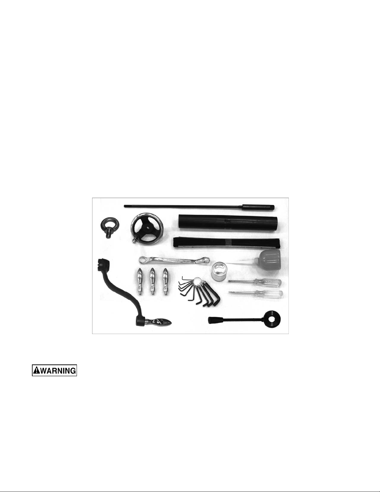
Contents of the Shipping Container
Note: Some parts may be pre- ins talled on the mill.
1 Turret Mill ( not shown)
1 Flat Way Cover
1 Pleated Way Cover
1 Draw Bar
3 Table Adjustment Handles
1 Tool Box, containing:
1 Hex Key Set (1.5-10mm) *
1 17/19mm Box Wrench *
1 Cross Point Screw Driv er #2 *
1 Flat Blade Scr ew Driver #2 *
1 Plastic Oil Bottle *
1 Elevating Cr ank Handle
1 Handwheel
1 Coarse Feed Handle
1 Can White Touch Up Paint
1 Eye Bolt
1 Operator’s Manual ( not shown)
1 Warranty Car d (not shown)
* parts with an asteris k are also inc luded in the
tool box service k it, p/n JTM4VS-TB.
Figure 1
Read and understand the entire contents of this manual before attempting set-up or
operation ! Failure to comp ly may cause serious injury.
If your mill is supplied with an optional Table Powerfeed and/or DRO, be sure to consult the separate instruction
materials that accompany them.
7
Page 8

Set-up and Installation
and-aft leveling. Be certain you get it level in
BOTH directions.
Preparing the Milling Machine for Service
1. Remove any crating which m ay be covering the
machine on the pallet .
2. Remove accessory items from the pallet or
machine tabl e. Compare t hese items wit h the list
on the previous page.
3. Check the ti ghtness of the lif ting ring on the r am
to be certain it i s tight.
4. Check the tightness of the lock handles on the
ram (see Figure 23) to be certain the ram is
locked tight.
5. Rem ove the nuts and/or bolts, which secure the
machine to the pallet.
6. Center an overhead crane or other suitable
overhead lifting device and sling arrangement
over the lifting ring.
Note: This machine weighs over 2400 pounds!
Be certain the lifting arrangement is new or in
excellent condition and has a safety factor that
will account for age, difficulties in lifting, etc.
When lifting using the ring, the machine will tip
forward. If y ou wish, y ou c an mi nimize this tipping
by rigging a support sling over the front of the
machine. B e careful when doing t his, to prevent
the sling f rom damaging any com ponents on the
front of the machi ne. Be sure to steady the mill t o
prevent it from spinning.
7. Lift the machine off the pallet no higher than
necessary to cl ear the hold- down hardware, then
pull the pall et out of the way. Do NOT get hand s
or feet underneath the machine when rem oving
the pallet!
8. Put the machine base over the hold-down system
where the mac hine will be spotted. Anchor bolts
of suffici ent size and length must be fast ened to
the floor ac cording to the footprint of the mill. See
diagram on page 10.
Note: The accompanying diagrams show you the
maximum dimensions of the machines with the
table, ram, etc., fully extended in all possible
directions. W hen spotting t he machine be cert ain
to leave room not only for the machine itself, but
also for operator clearance and clearance for
workers servic ing the machine, and any unusual
sizes of workpieces that might extend off the
machine’s tabl e.
9. W hen the machine i s over its anchor s, lev el the
machine using shim s under the corners needi ng
them. The machinist’s level used for leveling
should be placed on the table. The table is the
referenc e surface for both side-to-side and fore-
Mill must be supported equally
under all f our corners. Failure to comply may cause
the column to twist and put a bind in the table ways.
10. When the machine is level, secure the base to
the anchor system.
IMPORTANT: Before attempting to raise the mill
head, refer to Mill Head – Left/Right Adjustment in
the Adjustments section for procedures to safely
raise and set up the mill head.
11. Loosen the four hex head nuts (see A, Figure 22)
about 1/4 turn each (counterclockwise), just
enough to allow rot ation of the head.
12. While assisting the worm mechanism by putti ng
upward pressure on the m otor by hand, use the
wrench supplied with the machine to turn the
worm nut and raise the head to upri ght position.
13. Tighten the headbolts slightl y — not torqued —
just snug.
14. Using mineral spirits or other cleaning solvent,
clean all of the rust proofing from where it may
have been appli ed. Thi s is import ant; movi ng the
table or any other components bef ore removing
the rust proofi ng will onl y put rust proofi ng where
you don’t want it.
Some of the following steps may have already
been performed on t he mac hine. If so, ign ore the
instructions related to those particular steps.
Otherwise, perform them in the order listed,
referring to Figure 11 for any clarification.
15. Install the table traverse and cross-feed cranks
on their respective shafts using the nuts on the
shafts to secure the c r ank s.
16. Rem ove any rust proofing from t he drawbar and
its washer, and put the drawbar with washer
installed into the spindle c enter through the top of
the machine.
17. Slide the fine feed handwheel over the
handwheel hub and push it back until its rollpin
engages the hole in the hub and the wheel is
flush with the hub surf ac e.
18. Put t he coarse f eed handl e on the feed shaft and
tap it li ghtl y until it s roll pi n engages a hole i n t he
hub and it is flush against t he hub surface.
19. Unwrap and c lean the knee crank and install it on
it s shaf t .
20. I nstall the rubber way cov ers at front and behind
the table.
8
Page 9
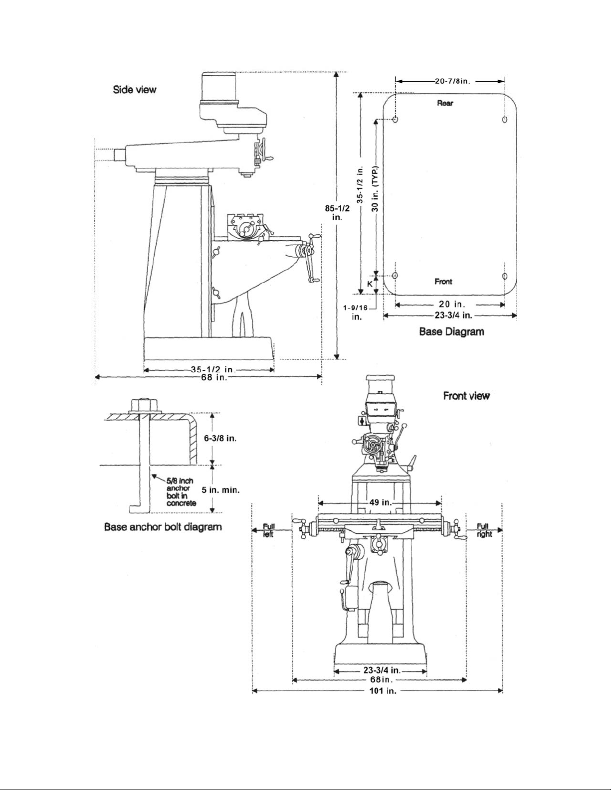
JTM-4VS Dimensions
Figure 2: Installation Diagram
9
Page 10
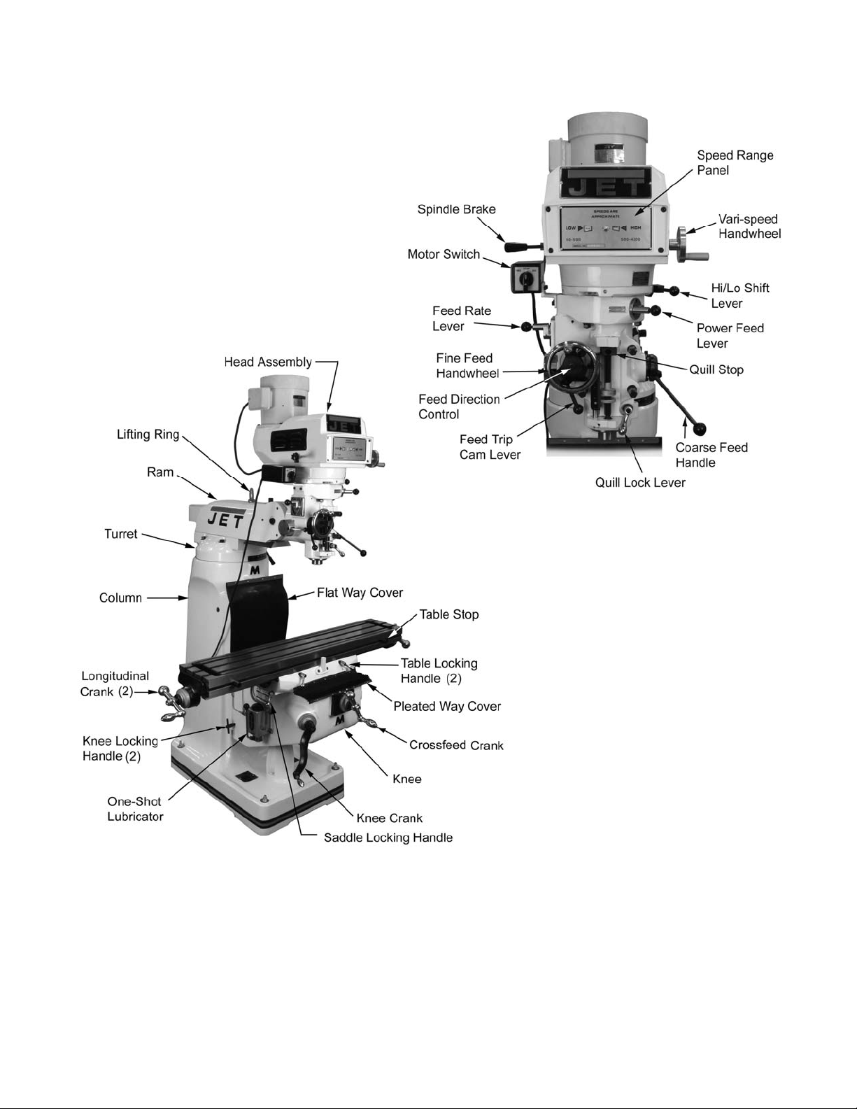
JTM-4VS Overview and Terminology
Figure 3: Overview
10
Page 11
Electrical Connections
Operating Instructions
All electrical connections must
be made by a qualified electrician! Failure to
comply may cause seriou s injury!
General Electrical Cautions
This machi ne must be grounded i n accordance with
the National Electrical Code and local codes and
ordinances. Thi s work should be done by a qual ifi ed
electrici an. The machine must be gr ounded to protect
the user from elect ri c al shock.
Wire Sizes
For circuit s which are far away from
the electrical service box, the wire size must be
increased in order to deliver ample voltage to the
motor. To minimize power losses and to prevent
motor ov erheating and burnout, the use of wir e sizes
for branch circuits or electrical extension cords
according to the following table is recommended:
Conductor
Length
0 – 50 Ft. No. 14 No. 14
50 – 100 Ft. No. 14 No. 12
Over 100 Ft. No. 12 No. 8
Confirm that power at the site matches power
requirements of the mill before connecting to the
power source.
The JTM-4VS has been pre-wired for 230 volt
operation. To c hange from 230V to the other voltage
offered, r emove the junction box cov er on the motor
and change the wires accordi ng to t he diagram found
on the inside of the cover.
Before connecting to the power source, make sure
that the switch is i n the off posi tion.
The mill must be properly grounded.
230/460 Volt Lines 120 Volt Lines
AWG Number
Figure 4
Operating Controls
The lubricati on system is a manuall y operated, oneshot system requiring operator intervention. The
operator must lower the one-shot lever to lubricate
the machine ways and ball screws. The one-shot
lubricati on system reserv oir i s loc ated on t he left side
of the machine.
The positi on of the milli ng machine mill head can be
set up to accommodate the work piece being
machined. T he mill head can be set up for angl es to
the left or ri ght and for for e and aft angl es. The mill
head can also be rot ated on its turret. The r am can
be moved back and forth to reach work piece
locations at the fore and aft extremes of worktable
travel. Refer to the Adjustments section.
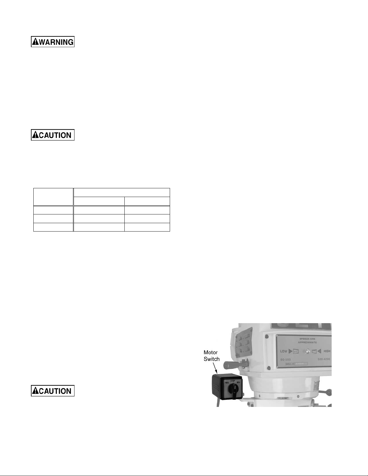
Motor Switch
The Motor Switch is on the upper left-hand si de of the
mill head (Fi gure 5). The switch has three po sitions:
FWD (forward), STO P, and RE V (reverse).
Setting the switch to FWD will provide clockwise
spindle rotation. Use FWD for normal, right-hand
tooling.
FWD (clockwise) operation occurs only when the
gearbox is in the low speed position. When the
gearbox is in high-speed position, the motor switch
must be in t he REV position t o provide ri ght-hand or
clockwise rotation. Refer to Figure 6 for a chart of
required switch positions.
The motor switc h controls a three-pha se motor. The
motor can be switched f rom FW D to REV and back
with the motor running, and will reverse direction
when the switch setting is changed. At higher
speeds, this may put strain on the timing belt but
there will be no damage to the motor or gear
mechanism.
Check for proper spi ndle rotation in the high-speed
range. The spindle should rotate clockwise when
viewed from the top of the machine. If the spindle
rotates counter-clockwise, disconnect from power
and switch two of the three power l eads.
Lubrication
Do not operate the mill before
lubricating the machine fully. Failure to comply
may cause damage to the machine.
Refer to the Maintenance/Lubrication section and
make sure the machi ne has been fully lubricated
before operating.
Figure 5
11
Page 12
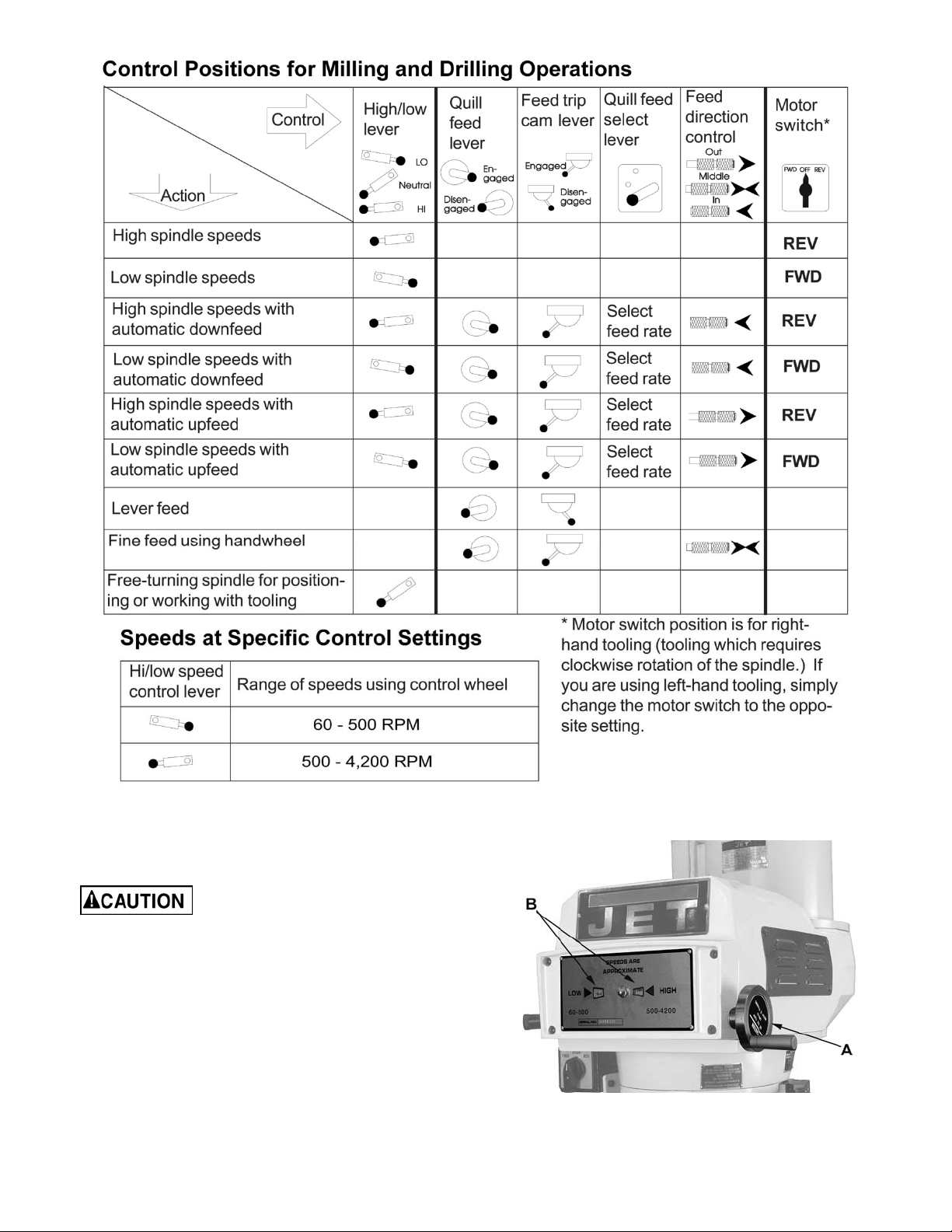
Figure 6
Variable Speed Control
Change speed only while the
spindle is turning.
The vari-speed handwheel (A, Figure 7) is used to
control the spindle speed. The speeds for high and
low speed ranges are displayed on t he panel on the
front of the mill head ( B, Figure 7).
All speed changes m ust be made while the motor is
running. Attempting speed changes without the motor
running can result in damage to the drive
mechanism.
Figure 7
12
Page 13

Spindle Brake
The spindle brake lever is located on the upper left
side of the mil l head (Figure 8). Pull lever downward
to apply the brake. The spindle brake lever is used
only after the m otor switc h has bee n set t o O FF . T he
spindle will not stop with the motor running.
Figure 8
High-Neutral-Low Shift Lever
The mill head can be dr iven directly (Hi gh Speed) or
through the back ge ar (Low Speed) i n the mill head.
The selection is made by changing the posi tion of the
shift le ver.
The shift lever is loc ated at the l ower ri ght side of the
mill head (Fi gure 9). The l ever position c losest to the
operator is the High sett ing. The l ever position away
from the operator is the Low setting. The middle
position is the Neutral setting.
Do not shift the High-Low Gear
Lever while the motor is
running. Rotate the spindle by hand to facilitate
changing lever positions.
Do not move the Quill Power
Feed Lever unless the motor is
at a complete stop. When changing the lever
position, do it gently. If the gear does not engage,
jog the motor and allow it to stop before
attempting to change.
The quill power f eed l ev er is l ocated on t he ri ght side
of the mill head (Fi gure 10). It is used to engag e and
disengage the quill power feed mechanism.
The power feed is engaged by pulling out the knob
and rotating the handle to a new locked position.
When engaged, t he power f eed m ec hanism will driv e
the spindle upward or downward. The power feed
mechanism will not drive the spindle when the handl e
is in the disengage position.
Figure 10
Feed Rate Lever
The Feed Rate Lever (Figure 11) is used t o set the
per-revolution rate of the power feed mechanism.
Three feed rates are available: 0.0015-inch, 0.003inch, and 0.006-i nch per r evolution. The posit ions are
shown on an indicator plate under the feed rate lever.
The rate is selected by pulling out the knob on the
feed rate lever and moving the handle to the detent of
the desired feed rate.
Figure 9
Quill Power Feed Lever
Do not use power feed at speeds
above 3000 R.P.M.
It is recommended to diseng age
the power feed worm gear
whenever the power feed is not required. This
avoids unnecessary w ear on the wo rm gear.
Note: The knob is spring loaded – pull out to rotate to
new position.
Unlike ot her controls on the m achi ne, the l ever shift s
into engagem ent more easil y with t he motor running,
and the quill feed lev er engaged.
Figure 11
13
Page 14

Feed Trip Cam Lever
Coarse Feed Handle
The Feed Trip Cam Lev er ( A, Figure 12) is located on
the left side of the head behind the Manual Fine Feed
Handwheel (B, Figure 12). It engages the overload
clutch on t he pinion shaf t when positioned t o the left .
The Feed Trip Cam Lever stays engaged until Quill
Stop (C, Figur e 15) c om es i n c ontact with Micrometer
Adjusting Nut (A, Figure 15) forcing it to drop out
automatically, or until it is released manually by
engaging the lev er t o the right.
Figure 12
Feed Direction Control
The Coars e Feed Handle ( A, Fi gure 14) i s located on
the right side of head. The Coarse Feed Handle is
used for non-precision drilling operations and for
moving the quill to a specific depth. A return spring
will retract the spindle automatically once the handle
is released.
Quill Lock Lever
The Quill Lock Lever (B , Fi gure 14) is loc ated on the
right side of the head. Rotat e the handl e cloc kwise to
lock the quill in a desired posit ion. Rotate the handle
counter-clockwise to release.
The Feed Direc tion Control (B, Figure 13) det ermines
whether the power feed will move up, down, or not
move at all. The positi on of the knob depends upon
the directi on of spindl e rotation (see the Motor Switch
section). T he positi on of the cont rol may be changed
with the system stopped or running. If the control
does not engage easily, move the fine feed
handwheel (A, Figure 13) back and forth to aid
engagement.
If the spindle is rotating clockwise, in is downf eed; out
is upfeed. If t he spindle rotation is countercl ockwise,
out is downfeed; in is upfeed. Neutral position is
between the in and out position.
It is recommend ed that the Feed
Direction Knob be left in the
neut r a l position when not in us e .
Figure 14
Micrometer Adjusting Nut
The Micrometer Adjusting Nut (A, Figure 15) is
located on the front of the head. Use for setting
specific spindle depth. Secure with the lock nut (B,
Figure 15).
Fine Feed Handwheel
When the controls are set for the Fine feed using
Handwheel position (see Figure 6), the Fine Feed
Handwheel (A, Figure 13) can be used for manual
fine feed control in either upward or downward
direction of t he quill.
Remove the Manual Fine Feed
Handwheel when not in use.
Failure to compl y may cause seri ou s injury.
Figure 13
14
Page 15

Depth Scale and Stop
Referring to Fi gur e 15:
The Depth Scale and Stop are used in drilling
operations to set the depth of the drilled hole. The
depth scale is located on the front of the mill head.
The scale consists of a Micromet er Adjusting Nut (A ),
Lock Nut (B), Quill Stop (C), Quill Stop Screw (D),
and Scale (E).
The Micrometer Adjusting Nut is set to the desired
dimension and locked in place using the Lock Nut.
The quill stop provides a positive stop for quill tr av el .
The graduations on the micrometer nut are in
0.001-inch increments. Adjustment of quill travel is
made by rotating the mic r om eter nut.
9. Select feed rate with the Variable Speed Control
Handwheel (E).
10. Set the Feed Rate Lever (B) to the feed rate
required for the tooling and material required.
11. Place the Quill Feed Engagement Lever (F) in
the Engaged position.
12. Select feed direction by setting the Feed
Direction Knob (C) posi tion per the table:
Spindle Dir. Feed Dir. Knob Pos.
CW
CCW
13. Engage the Feed Trip Cam Lever (D) by pulling
away from head assembl y .
Note: Due to variables in tool diameter, coatings,
coolant, and materials, no specific spindle speed or
feed rate recommendations are provided. Use
general shop manuals that have data applicable to
the milling and drilling operations being performed.
Or, contact the supplier of the tooling, coolant, and
material for specif ic recommendations.
Down In
Up Out
Down Out
Up In
Figure 16
Figure 15
Power Feed Operation
The F eed Tr ip Adjust ment sets the poi nt at which t he
quill will reset dur ing Power Feed.
Referring to Fi gur e 17:
Be sure that the Manual Fine
Feed Handwheel is removed.
Failure to compl y may cause seri ou s injury.
1. Loosen the Locknut ( I).
2. With the Quill Feed Handle (J), advance the quill
to the point where the f eed shoul d stop.
3. Engage the Feed Tr ip Cam Lever ( D) by pulling
away from head assembl y .
4. Adjust Microm eter Adjusting Nut (H) against
Quill Stop (G).
5. Continue tur ning the Micrometer Adjusting Nut
(H) until the Feed Trip Cam Lever (D) trips.
6. Tighten the Locknut (I).
7. Ensure Quill Lock (K) is di sengaged by r otating
counter-clockwise.
8. Start the spindle (A):
IMPORTANT: The po wer feed can be u sed for dr ills
up to 3/8” in di ameter (mild steel ). Use manual f eed
for drills l ar ger than 3/8”.
The o verl oad clutch is f acto ry set
to hold up to 200 lbs. down feed pressure on the
quill (accommodates drills up to 3/8”). Do not
attempt to adju st clutch p r essure.
Figure 17
15
Page 16
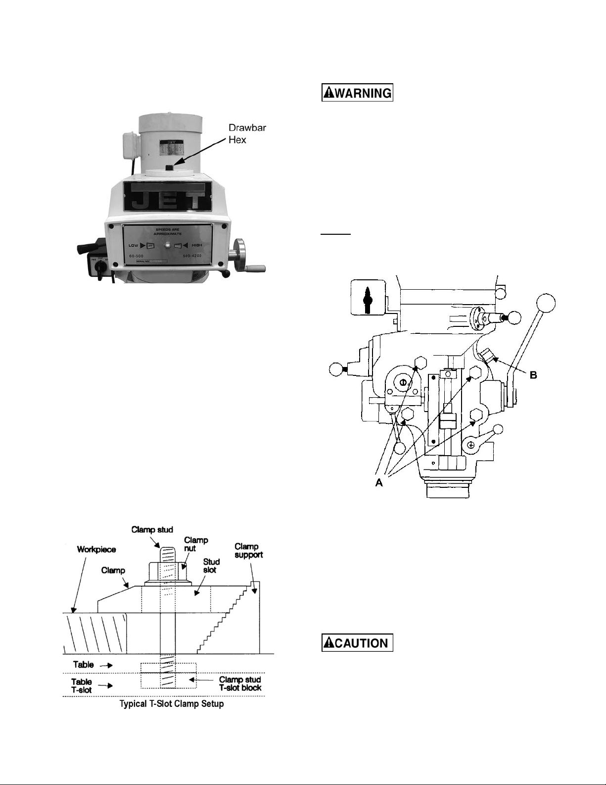
Draw Bar Operation - Changing Tooling
1. Using the wrench provided with the machine,
loosen the draw bar two or three turns (turn
counterclockwise) using the draw bar hex
(Figure 18).
Figure 18
2. Tap the top of the draw bar with a soft-faced
hammer to loosen the collet from the taper.
Adjustments
Mill Head – Left/Right Adjustment
Make sure the machine base is
secured to the floo r before repositioning the mill
head. The center of gravity can shift enough to
cause the machine to tip over, resulting in
serious injury to the operator and damage to the
machine.
1. Loosen four large hex nuts that secure the mill
head to the ram adapter (r efer to Figure 20).
1/4 turn should be suffici ent to allow the head to
move.
NOTE: For angles great er than 10 degrees, use your
free hand to support the mill head, taking some
weight off the brass worm gears. Doing so will greatly
lengthen the lif e of t he worm gear s.
3. Remove the tool from the collet.
4. Insert the tool y ou ar e going to use into the collet.
5. Tighten the draw bar firmly using the wrench
provided with the machine. Turn the draw bar.
The tool is now ready for use.
Clamping Work Piece to the Table
1. The worktable has 5/8-inch T-slots for clamping
the work piece to the t able.
2. Set motor switch to STOP position.
3. Place the work piece on the t able.
4. Clamp the work piece using the T-slot clamps,
studs, and step block s as requir ed ( Figure 19).
Figure 20
2. Turn the worm nut (B, Fi gure 20) to til t the head
left or right as required. Use the scal e on the ram
adapter to set the desi r ed angle.
Note: The scales on the ram adapter and for
head rotation are guides only. Close tolerance
work will require the use of a dial indicator to
make sure the head i s 90° to t he table in the X
and Y axis. P lease note the table i s fitted to be
slightly higher in front, usually about 0.0005” .
Figure 19
Be sure to apply torque in two
steps using a crossing pattern. Failure to do so
could distort the f ace of th e ram adap t er.
3. Tighten the four hex nuts. Tighten in two steps
using a cali br ated torque wrench. Use a crossing
pattern to tight en the nuts. Tight en initiall y to 25
foot-pounds.
16
Page 17

4. Before applyi ng final torque, check to make sure
the mill head is perpendi c ular to the worktable.
5. Set up a dial indicator in a collet and secure
using the draw bar (refer to Figure 22).
2. Returning to upright posi tion:
a. When retur ning the mill head t o its full upr ight
position, be sure to support the head by upward
pressure on the spindle as you t ur n the worm nut.
6. Put the spindle driv e in neutral.
7. Set the dial indicator plunger on the worktable.
Zero the indicat or .
8. Rotate the spindle 180 degrees (when rotating,
raise the dial indicator plunger by hand t o pr event
it from dropping into the table T-slots).
9. Read the di al indi cat or. The indic ator should read
zero. If not, loosen the four hex nuts and
reposition the mill head.
10. Recheck per pendic ular it y using t he di al i ndic ator.
Repeat the procedure above until the dial
indicator r eads zero in both positions.
Be sure to apply torque in two
steps using a crossing pattern. Failure to do so
could distort the f ace of th e ram adap t er.
11. Tighten the four hex nuts. Tighten in two steps
using a cali br ated torque wrench. Use a crossing
pattern to tight en the nuts. Tight en initiall y to 25
foot-pounds, then tighten to a final torque of 50
foot-pounds.
Mill Head – Fore/Aft Adjustment
1. Setting the angle:
a. Loosen the three ram adapt er clamp bolts on
the ram (A, Figure 21). There is no need to
loosen the bolts more than 1/2 turn to allow
tilting.
b. Check to make sure the mill head is perpendicular to the worktable.
c. Set up a dial indicator in a coll et and secure
using the draw bar (refer to Figure 22).
Figure 22
d. Put the spindl e drive in neutral.
e. Set the di al indi cat or plunger on t he worktabl e.
Zero the indicat or .
Figure 21
b. Support the mill head with your free hand.
Press upward on the spindl e when changing the
angle.
c. Turn t he ram adapter worm nut (B, Figure 21)
to tilt the head forward and backward. Use the
scale on the ram adapter to locate the desired
angle.
f. Rotate the spi ndle 180 degrees (when rotati ng,
raise the dial indicator plunger by hand t o pr event
it from dropping into the table T-slots).
g. Read the dial indicator. The indicator should
read zero. If not, loosen the four hex nuts and
reposition the mill head.
h. Recheck perpendicularity using the dial
indicator. Repeat the procedure above until the
dial indicator reads zero in both positions.
i. When the indi cator reads zero, tight en the ram
adapter clam p bolts.
17
Page 18

Positioning the Ram
Posi tioning the Ram Fore and Aft
1. Loosen the two bol ts (A, Figure 23) t hat lock the
ram to its ways.
Figure 23
2. Turn the l ever (B, Fi gur e 23) to mov e the ram on
its ways.
3. When the desired position is reached, lock the
bolts (A, Figure 23) securely.
Posi tioning the Ram on its Turret
Make sure the machine base is
secured to t he fl oor b efore rep o sitioning t he ram.
The center of gravity can shift enough to cause
the machine to tip over, resulting in serious injury
to the operator and damage to the machine.
1. Loosen four turret lock bolts (C, Figure 23) that
clamp the ram to the top of the base. 1/2 turn
should be sufficient to allow the turret to move.
Figure 24
Adjustm e nt of K ne e Gib
The knee gib adjustment screw (A, Figure 24) is
located under t he chip wiper at the rear of t he knee
where it cont act s the col um n. Remov e t he way cov er
and the wiper to expose the gib adjustment screw.
Tighten the screw until a slight drag is felt when
turning the knee cr ank .
Adjustm e nt of S a d dle Gib
The saddle gib adjustment screw is on the l eft front of
the saddle (B, Figure 24). Tighten the screw until a
slight drag is felt when turning the cross-feed cr ank .
Adjustm e nt of Ta ble Gib
The table gib adjustm ent screw (C, Figure 24) is on
the left-hand side, beneath the table. Tighten the
screw until a slight drag is felt when turning the
longitudinal table cranks.
Note: Use gentle hand pressure to avoid rapid
movement.
2. Turn the ram until the spindle is in the desired
position. Use the scale on the turret for degree
measurement.
3. Tighten the four turret lock bolts (C. Figure 23).
Gib Adjustment
The table, saddle and knee are equipped with
adjustable gibs. The gibs may require adjustment if
unusual vibration is noted when the locking
mechanisms are off, or if you experience unusual
vibration when spi ndle speed, tooth pi tch or depth of
cut do not account f or the v ibr ation.
NOTE: When adjusting gibs, always start with the
knee first; adjust the saddle second, and adjust the
table last.
18
Page 19
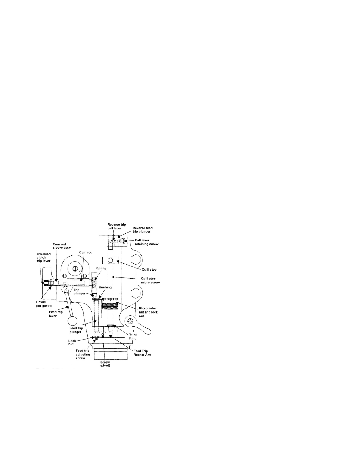
Power Feed Trip Lever Mechanism
Refer to Figure 25.
The power feed tri p lever mechanism will need to be
adjusted if worn or whenever any trip lever
mechanism component s are replaced.
1. Loosen the feed tri p adjusting screw lock nut.
2. Loosen the adj usti ng screw until it is l oose in the
lever and no longer contacts the bottom of the
feed trip plunger.
3. Using t he coarse feed handle, move the quill t o
the bottom of it s travel so the quill stop contacts
the micromet er nut. Hold the quill on the stop.
4. Pull the feed handle out to engage the power
feed system.
5. Turn the f eed trip adjusting screw unti l the power
feed disengages.
power feed. If not, readjust t he mechanism until
positive di sengagement occurs when the qui ll is
at the top of its stroke.
10. Check for correct oper ation using the coarse f eed
handle. If operating correctly, start the drive
motor and engage the power feed mechanism.
Verify that the power feed lever correctly
engages and disengages when driven by the
drive motor.
Table Lead Screw Backlash Adjustment
Refer to Figure 26.
The milling mac hine table is moved by a lead screw
and nut for eac h machine axi s. For proper oper ation,
there must be c lear ance between the l ead screw and
the nut, which results in backlash. A second lead
screw nut is provided to eliminate most of the
backlash. The following procedures provide
instructions for obtaining acceptable backlash.
6. Tighten the feed trip adjusting screw.
7. Release the quill stop so you can engage the
power feed mec hanism using the power f eed tri p
lever.
8. Using t he coarse feed handle, pull the quill stop
back into firm cont ac t wit h the mi c r om eter nut.
Cross Feed Backlash Adj ustment
1. Use the cross feed crank to m ove the table to the
extreme rear of i ts t rav el.
2. Remove the pleated way cover.
3. Open the two chip guar ds enough to ex pose the
cross-feed adj ustment nut (the nut t hat is toward
the rear of t he nut bracket is not adjustable – only
the front nut is adjustable).
4. Loosen the two nut loc ki ng screws.
5. Turn the nut slightly to tighten it against the
opposing nut.
6. Tighten the two nut loc ki ng screws.
7. Using the cro s s-feed crank, move the table to the
middle position.
8. Set up a dial indicator to check cross-feed
backlash. Gentl y move the cross feed c rank bac k
and forth while watching the dial indicator.
Backlash should be between 0.003 inch and
0.005 inch.
9. If necessary, repeat the steps above to set
backlash.
Figure 25
Note: The power feed should disengage when the
quill stop pushes on the m icrometer nut. If it does not
disengage, repeat t he adjustment steps above.
9. Engage t he power feed and move t he quill stop
to the top of its travel. Make sure that the
reverse trip mechanism also disengages the
10. I nstall the pleated way cov er.
Longitudinal Backl ash Adjustment
Refer to Figure 26.
1. Only one of the longit udinal lead screw nuts c an
be adjusted. The ot her nut is fixed. The left hand
nut is typically adjustable. This can be
determined by looking at the nut from the
underside of the table.
2. Loosen the two nut loc ki ng screws.
3. Turn the nut slightly to tighten it against the
opposing nut.
19
Page 20

4. Tighten the two nut loc ki ng screws.
5. Using the longitudinal table crank, move t he table
to the middle position.
6. Set up a dial indicator to check longitudinal
backlash. Gentl y move the crank bac k and forth
while watching the dial indicator. The backlash
should be between 0.003 i nc h and 0.005 inch.
If necessary, repeat the steps above to set backlash.
Figure 26
20
Page 21

Maintenance
Before any intervention on the machine, disconnect it from the electrical supply by
pulling out the plug or switching off the main switch! Failure to comply may cause serious injury.
Lubrication
The milli ng machine is equipped with a “ one-shot” lubr ication system. T he system lubricates the l ead screws
and ways. An oil cup and grease ni pple on the mill head provide lubri cation for the spindle bearings and back
gear mechanism . Ref er to Figures 28 and 29 for lubrication requir em ents and access points.
Key Description Recommended Lubricant Action
A Spindle bearing oil cup Mobil DTE Oil Light, or equiv alent Service daily .
Check oil daily – add if required.
B One-shot lube system Mobil Vactra Oil #2, or equiv alent
Knee leadscrew grease
C
nipple
Mobilith AW2, or equivalent Service once each week.
Pull lube handle every hour
during operations.
D Back gear grease nipple Mobilith AW1, or equivalent
Figure 27: Lubrication Points
Periodic Maintenance Requirements
During operation, periodically vacuum and brush
chips and debris from m ac hine.
Periodically operate knee and table lead screws
through full r ange of movement to evenly distri bute
lubricant (particularly when appl ied using the “oneshot” system ).
Periodic ally apply light machine oil to work tabl e and
other exposed metal surfaces to prevent rust or
corrosion.
Figure 28
Periodically remove vent panels to check pulleys
and belts for unusual wear or grooving. NOTE:
Operators s hould v ar y s peed oc c as ionally to prevent
formation of gr oov es on the pulley s ur faces.
Service weekly when operating
in back gear mode.
Figure 29
21
Page 22

Replacement of Drive Motor
Refer to Figur e 30 and Head Assembly in the Parts
section.
Figure 30
1. Operate spindle at its highest speed.
Disconnect electrical power to
the machine befo re performing any maintenance.
2. Disconnect electrical power. Remove junction
box cover and disconnect wiring. Tag wires to
identify leads for reinstallation.
3. Remove vent covers on both sides of head to
provide access to the v ari - speed bel t and pulleys.
4. Remove the lower cover plate under the motor
pulley (at the rear of the cover) by removing three
cap screws.
5. Remove the four screws that attach the motor.
6. Connect a lifting sl ing to support and lift the motor
during removal. Ease the motor up and forward
on the housing.
7. Til t the motor slightly toward the rear t o slacken
the vari-speed belt. Remove the vari-speed belt
from the motor pulley.
10. Slowly release pressure on hydraulic ram until
the spring (ref . 8) is fully extended.
11. Remove the lengthening shaft (ref. 106), spring
stop washer (ref. 9), spring (ref. 8) and outermost
pulley (ref. 5) from the moto r shaft.
12. Loosen set screw (ref. 3) on innermost pulley
(ref. 2). Remove the pulley (ref. 2) and drive key
(ref. 7) from the motor shaft.
13. Install drive key (ref. 7) and pulley (ref. 2) on
shaft of replacement motor. Tighten set screw
(ref. 3) on pulley .
14. Support the drive motor in a hydraulic press.
Place the out ermost pul ley (ref. 5) on the motor
shaft.
15. Instal l the spring (r ef. 8), spring stop washer (ref .
9), and lengtheni ng shaft (ref. 106) on the m otor
shaft.
16. Move the hydraulic ram into contact with the
spring stop washer (ref . 9). Compr ess the spring
(ref. 8) and i nstal l the l engtheni ng shaf t (ref. 106)
on the motor shaft. Install and tighten the
attaching scr ew (ref . 107) i n the end of the m otor
shaft.
17. Using an overhead hoist, lift the replacement
motor into position.
18. Tilt t he motor sli ghtly toward the rear and install
the vari-speed belt on the motor pulleys.
19. I nstall the four motor att ac hing screws.
20. I nstall lower cover plate.
21. Connect electric al wiri ng to motor junction box.
22. Start the drive motor. Operate the spindle
throughout its speed range to check operation.
23. I nstall vent covers on mill head.
8. Remove the belt; lift the motor clear of the
housing.
Do not attempt to remove the
screw from the end of the motor shaft without
use of a hydraulic press. Failure to comply may
cause serious inj ury.
The screw retains the underl ying spri ng stop washer,
which is under spring tension. Serious injury can
result if the spring tension is not gradu ally released
using the hydraul ic pr ess. Proc eed as follows.
9. Support the drive motor in a hydraulic press.
Move the hydraulic ram into contact with the
spring stop washer (ref. 9). Remove the screw
(ref. 107) from the end of t he m otor shaf t.
Figure 31
22
Page 23
Replacement of Vari-Speed Belt
Refer to Figures 31 and 32, and Head Assembly in
the Parts section.
Disconnect electrical power to
the machine befo re performing any maintenance.
1. Rem ove driv e mot or (refer t o the Replacement of
Drive Motor section).
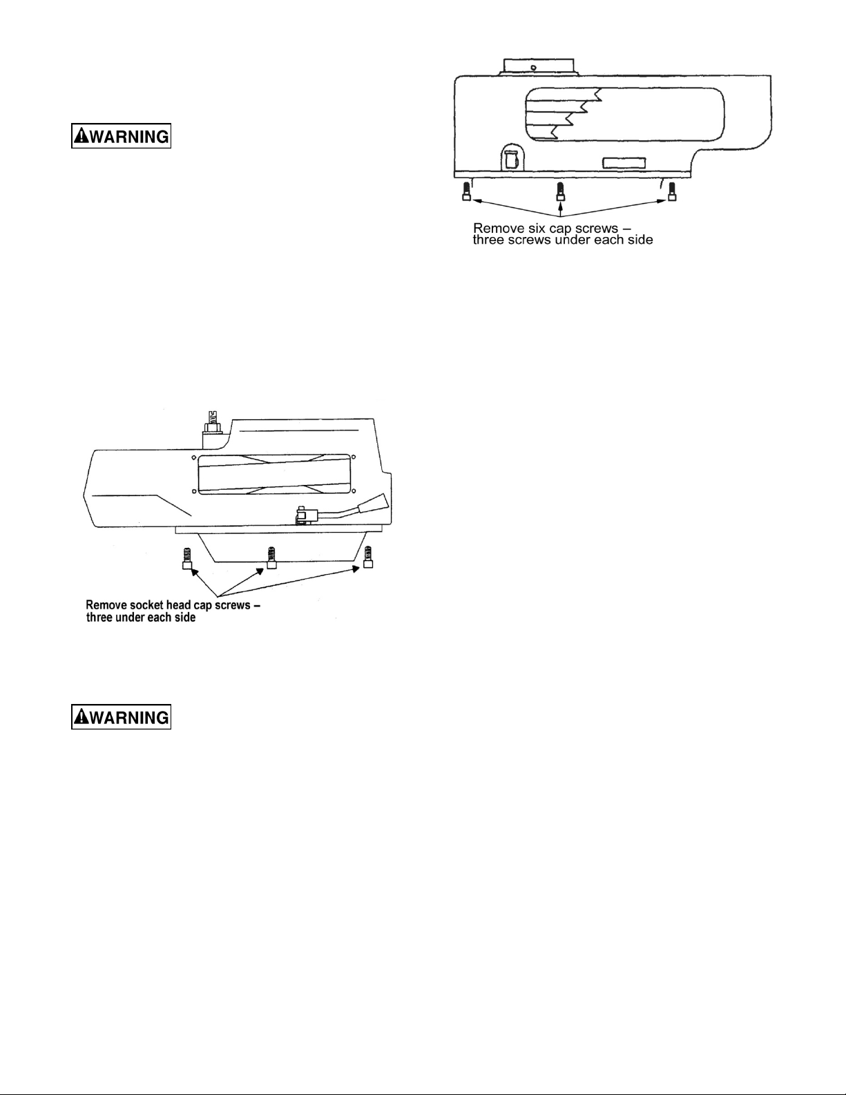
2. Remove Quill Top Cover by removing t hree cap
screws (Figur e 31) .
3. Remove six cap screws and remove the upper
housing (Figur e 32) .
4. Remove the vari-speed bel t (ref. 4).
5. Install the new vari-speed belt (ref. 4) on the
driven hub (ref. 44) .
6. Install drive motor (refer to the Replacement of
Drive Motor section).
Figure 33
6. Pull the piv ot fi nger stud (ref . 58) out of t he l ower
housing cover (ref. 50) and the brake pivot
fingers (ref . 59).
7. Before removing, note the orientation of the
brake pivot finger s (ref. 59) for correct positi oning
for re-assembl y . Remov e the pivot fingers.
If replacing the brake c omponents only, skip Steps 8
and 9 and go to Step 10.
To replace the timing belt :
8. Remove lower housing cover and pulley.
Figure 32
Replacement of Brake Shoes, Springs and/or Tim in g Belt
Disconnect electrical power to
the machine befo re performing any maintenance.
1. Rem ove driv e mot or (refer t o the Replacement of
Drive Motor section).
2. Rem ove vari -speed belt and upper housing ( ref er
to the Replacement of Vari-Speed Belt section).
3. Remove screws from lower housing cover
(ref. 50).
4. Loosen the setscrew (ref. 3) securing the brake
pivot finger stud (ref. 58) in the lower housing
cover (ref. 50).
5. Move the pivot finger stud (ref. 58) inward
enough to remov e the snap ri ng ( r ef. 60).
9. Replace belt (r ef 63).
To replace the brak e c omponents :
10. Using a soft -f aced mallet, tap upward to separate
the lower housing cover (ref. 50) and the brake
assembly (ref . 47) from the bearing (ref. 43).
11. Remove the brake shoes (ref. 47) and springs
(ref. 49). I nstall the replac ement br ake shoes and
springs.
For all:
12. Positi on the brake piv ot fingers (ref. 59) as noted
during removal. Install the pivot finger stud (ref.
58) through the l ower housing c ov er (ref. 50) and
into the brake pivot fingers (ref. 59). Install the
snap ring (ref. 60) on the pivot finger stud (ref.
58).
13. Tight en the setscrew (ref. 3) to secure the piv ot
finger stud (r ef. 58) .
14. Instal l the brake assembl y (ref. 47) on the l ower
housing cover ( r ef. 50).
15. Sec ur e the lower housing cover (ref. 50) with four
screws.
16. I nstall timing belt and upper housi ng.
17. Install vari-speed belt (refer to the Replacement
of Vari-Speed Belt section).
18. Install drive motor (refer to the Replacement of
Drive Motor section).
23
Page 24

Replacement of Quill Feed Clock Spring
Refer to the Spindle Assembly in the Parts section.
Disconnect electrical power to
the machine befo re performing any maintenance.
1. Remove the coarse feed handle.
2. Remove the screw, hub, and key from t he c oarse
feed shaft (ref . 172, 175, and 171).
3. Rem ove six screws (Ref. 1) and allow the clock
spring (ref. 178) to slowly unwind.
4. Remove feed handle hub sl eeve (ref. 176).
5. Lif t the end of the spring (ref . 178) from the pin
(ref. 168) on the pinion shaft (ref. 166).
6. Remove the spring (ref. 178) from the spring
cover (ref. 177).
7. Install the replacement spring (ref. 178) in the
spring cover (ref 177).
8. Install end of spring (ref. 178) over the pin
(ref. 168) on pinion shaft (ref. 166).
9. Install pin (ref. 168) in feed handle hub sleeve
(ref. 176) on other end of spri ng ( r ef. 178).
10. T ur n the spring cover (ref. 177) to wind the spring
(ref. 178). Turn the spring cover (ref. 177) until
the desired ten sion i s achiev ed. Hold the spring
cover (ref. 177) in position and secure with six
screws (ref. 1).
11. I nstall the key, hub, and screw (ref. 171, 175, and
172) onto the feed shaft (ref. 166).
Replacement Parts
Replacement par ts are listed on the following pages. To order parts or reach our service department , call 1-800274-6848, Monday through Friday (see our website for business hours, www.jettools.com). Having the Model
Number and Serial Number of your machine available when you call will allow us to serve you quickly and
accurately.
24
Page 25

Head Assembly
25
Page 26

Parts List for Head Assembly
Index No. P art No. Description Size Qty
................. JTM4VS-HA ............ Head Assembly w/ Motor ................................... ............................................... 1
1 ............... VS-001 .................... Upper Housing ................................................... ............................................... 1
2 ............... VS-002 .................... Motor Pulley ...................................................... ............................................... 1
................. VS-044A ................. Motor Pulley Bushing (not shown) ...................... ............................................... 1
3 ............... TS-1503011 ............ Set Screw .......................................................... M6 x 6 .................................... 4
4 ............... VS-004 .................... Belt .................................................................... 900VC3830 ............................ 1
5 ............... VS-005 .................... Motor Pulley Disk ............................................... ............................................... 1
6 ............... VS-006 .................... Motor Pulley Shaft ............................................. ............................................... 1
7 ............... KEY7725 ................. Key .................................................................... 7 x 7 x 25 mm ......................... 1
8 ............... VS-008 .................... Motor Pulley Spring ........................................... ............................................... 1
9 ............... VS-009 .................... Spring Stop Washer ........................................... ............................................... 1
11 ............. VS-011A ................. Moto r Pulley Cover ............................................ ............................................... 1
12 ............. TS-1502051 ............ He x So ck e t Cap S cr e w ...................................... M 5 x 20 .................................. 8
13 ............. VS-013 .................... Cover................................................................. ............................................... 1
14 ............. TS-1503041 ............ He x So ck e t Cap S cr e w ...................................... M 6 x 16 ................................ 1 0
15 ............. BB-6007ZZ.............. Ball Bearing ....................................................... ............................................... 1
16 ............. VS-016 .................... Dial Cover .......................................................... ............................................... 1
16-1 .......... VS-016-1 ................. Dial With Panel Assembly (not shown) ............... ............................................... 1
17 ............. TS-1503071 ............ He x So ck e t Cap S cr e w ...................................... M 6 x 30 .................................. 4
18 ............. TS-1503041 ............ He x So ck e t Cap S cr e w ...................................... M 6 x 16 .................................. 2
19 ............. VS-019 .................... Bushing ............................................................. ............................................... 1
20 ............. VS-020 .................... Bushing ............................................................. ............................................... 1
21 ............. VS-021 .................... Wor m................................................................. ............................................... 1
22 ............. VS-022 .................... Wor m Gear ........................................................ ............................................... 1
23 ............. VS-023 .................... Spring Pin .......................................................... 5 x 10 mm ............................... 2
24 ............. VS-024
25 ............. VS-025 .................... Dial Control Shaft ............................................... ............................................... 1
26 ............. VS-026 .................... Spring Pin .......................................................... 3 x 12 mm ............................... 1
27 ............. VS-027 .................... Dial Whee l ......................................................... ............................................... 1
28 ............. VS-028 .................... Whee l Handle .................................................... ............................................... 1
29 ............. VS-029 .................... Shaft .................................................................. ................................ ............... 1
30 ............. VS-030 .................... Spring Pin .......................................................... 4 x 16 mm ............................... 2
31 ............. VS-031 .................... Spring Pin .......................................................... 3 x 25 mm ............................... 1
32 ............. VS-032 .................... Speed Change Chain ......................................... ............................................... 1
33 ............. VS-033 .................... Adjustment Stud ................................................ ............................................... 1
34 ............. VS-034 .................... Sleeve Nut ......................................................... ............................................... 1
35 ............. VS-035 .................... Adjustment Stud ................................................ ............................................... 1
36 ............. VS-036 .................... Tilter .................................................................. ............................................... 1
37 ............. VS-037 .................... Bushing ............................................................. ............................................... 2
38 ............. KEY6645 ................. Key .................................................................... 6 x 6 x 45 mm ......................... 1
39 ............. VS-039 .................... Regulat ing Screw............................................... ............................................... 1
40 ............. VS-040 .................... Spring Pin .......................................................... 3/32” x 3/4" ....................... ...... 1
41 ............. VS-041 .................... Wash er .............................................................. ................................... ............ 1
42 ............. VS-042 .................... Support .............................................................. ............................................... 1
43 ............. BB-6010VV ............. Ball Bearing ....................................................... ............................................... 2
44 ............. VS-044 .................... Driven Pulley Assembly (s/n:xxx1944 & lower) ... ............................................... 1
................. VS-044N ................. Driven Pulley Assembly (s/n:xxx1945 & higher) .. ............................................... 1
45 ............. VS-045 .................... Steady Pulley (s/n:xxx1944 & lower) .................. ............................................... 1
................. VS-045N ................. St
46 ............. VS-046 .................... Bearing Cover ................................................... ............................................... 1
47 ............. VS-047 .................... Brake Lining ...................................................... ............................................... 1
48 ............. VS-048 .................... Lock Screw ........................................................ ............................................... 1
49 ............. VS-049 .................... Brake Spring ...................................................... ..................................... .......... 2
50 ............. VS-050 .................... Lower Housing Cover ........................................ ............................................... 1
51 ............. TS-1504031 ............ He x So ck e t Cap S cr e w ...................................... M 8 x 20 .................................. 4
52 ............. VS-052 .................... Brake Shaft Sleeve ............................................ ............................................... 1
53 ............. VS-053 .................... Brake Lock Shaft ............................................... ............................................... 1
.................... Bush ing ............................................................. ............................................... 2
eady Pulley (s/n:xxx1945 & higher) ................. ............................................... 1
26
Page 27

Index No. P art No. Description Size Qty
54 ............. VS-054 .................... Brake Lock Block ............................................... ............................................... 1
55 ............. TS-1503061 ............ He x So ck e t Cap S cr e w ...................................... M 6 x 25 .................................. 1
56 ............. VS-056 .................... Brake Lock Handle ............................................ ............................................... 1
57 ............. VS-057 .................... Plastic Ball ......................................................... ............................................... 2
58 ............. VS-058 .................... Brake Finger Piv ot Stud ..................................... ............................................... 1
59 ............. VS-059 .................... Brake Stud ......................................................... ............................................... 2
60 ............. VS-060 .................... Snap Ring.......................................................... S-8 ......................................... 2
61 ............. TS-0561072 ............ Nut .................................................................... 5/8”-1 8 UNF ............................ 1
62 ............. VS-062 .................... Timing Belt Pulle y .............................................. ............................................... 1
63 ............. VB-225L100 ............ Timing Bel t ........................................................ 225L100 ................................. 1
64 ............. VS-064 .................... Bearing Retainer ................................................ ............................................... 1
65 ............. BB-6203ZZ.............. Ball Bearing ....................................................... ............................................... 2
66 ............. VS-066 .................... Bull Gear ........................................................... ................................... ............ 1
67 ............. VS-067 .................... Counter Shaft .................................................... ............................................... 1
68 ............. VS-068 .................... Key .................................................................... 5 x 5 x 15 mm ......................... 1
69 ............. VS-069 .................... Key .................................................................... 5 x 5 x 18 mm ......................... 1
70 ............. VS-070 .................... Spindle Pu l le y Hu b ............................................ ............................................... 1
71 ............. VS-071 .................... Key .................................................................... 8 x 7 x 24 mm ......................... 1
72 ............. VS-072 .................... Key .................................................................... 8 x 7 x 12 mm ......................... 1
73 ............. VS-073 .................... Spindle Gear Hub .............................................. ............................................... 1
74 ............. VS-074 .................... Spindle Gear Ass embly ...................................... ............................................... 1
75 ............. VS-075 .................... Rack Cup........................................................... ............................................... 1
76 ............. VS-076 .................... Wash er .............................................................. ................................... ............ 1
77 ............. BB-6908ZZ
78 ............. VS-078 .................... Bearing Washer ................................................. ............................................... 1
79 ............. VS-079 .................... Bearing Washer ................................................. ............................................... 1
80 ............. VS-080 .................... Snap Ring.......................................................... ............................................... 1
81 ............. VS-081 .................... Nut .................................................................... ............................................... 1
82 ............. VS-082 .................... Lower Housing ................................................... ............................................... 1
83 ............. VS-083 .................... Fixed Clutch Bracket .......................................... ............................................... 1
84 ............. VS-084 .................... Spring ................................................................ ................................. .............. 1
85 ............. VS-085 .................... Stud ................................................................... ............................................... 3
86 ............. TS-1506021 ............ He x So ck e t Cap S cr e w ...................................... M 1 2 x 25 ................................. 3
87 ............. VS-087 .................... Gear Shift Pinion................................................ ............................................... 1
88 ............. VS-088 .................... Pin ..................................................................... ............................................... 1
89 ............. VS-089 .................... Detent Plate ....................................................... ............................................... 1
90 ............. VS-090 .................... Detent Washer ................................................... ............................................... 1
91 ............. VS-091 .................... Spring ................................................................ ................................. .............. 1
92 ............. VS-092 .................... Pinion Block ....................................................... ............................................... 1
93 ............. TS-1503011 ............ He x So ck e t Cap S cr e w ...................................... M 5 x 14 .................................. 2
94 ............. VS-094 .................... Pinion Crank ...................................................... ............................................... 1
95 ............. VS-095 .................... Cap Nut ............................................................. ............................................... 1
96 ............. TS-0561031 ............ Hex Nut ............................................................. 3/8” ......................................... 1
97 ............. VS-097 .................... Snap Ring.......................................................... ............................................... 1
98 ............. VS-098 .................... Wa ve Washer .................................................... ............................................... 1
99 ............. VS-099 .................... Plastic Ball ......................................................... ............................................... 1
100 ........... VS-100 .................... Snap Ri ng.......................................................... ............................................... 1
101 ........... VS-101B ................. Co ver................................................................. ............................................... 2
102 ........... VS-102
103 ........... VS-103 .................... Washe r .............................................................. ................................... ............ 1
104 ........... VS-104 .................... Copper Washer ................................................. ............................................... 2
105 ........... VS-105 .................... Screw ................................................................ 1/4 " x 3/8” ............................... 8
106 ........... VS-107 .................... Shaft .................................................................. ................................ ............... 1
107 ........... TS-1504061 ............ He x Soc ke t Ca p Sc re w ...................................... M8 x 30 .................................. 1
109 ........... VS-109 .................... Lock Washe r...................................................... ............................................... 1
110 ........... TS-1540041 ............ Hex Nut ............................................................. M6 ......................................... . 1
111 ........... TS-0209051 ............ He x Soc ke t Ca p Sc re w ...................................... 3 /8 ” x 1” .................................. 4
112 ........... VS-000 .................... Motor ................................................................. 3H P 3PH ................................ 1
................. JTM4VS -112 ........... Moto r ................................................................. 2H P 1PH ................................ 1
113 ........... VS-113 .................... Oval Head Screw ............................................... 1/8” x 1/4" ............................... 4
.............. Ball Bearing ....................................................... ............................................... 2
.................... Spring Shaft ....................................................... .................................... ........... 3
27
Page 28

Index No. P art No. Description Size Qty
114 ........... JTM1-001VS ........... Draw Bar ........................................................... ............................................. .. 1
115 ........... JTM4VS-A002B ...... Draw Bar Washer .............................................. ............................................... 1
116 ........... VS-116 .................... Key .................................................................... ............................................... 1
117 ........... VS-117 .................... Oval Head Screw ............................................... 3/16” x 1/2” ............................. 1
118 ........... VS-007 .................... Snap Ri ng.......................................................... ............................................... 4
119 ........... VS-005A ................. Plas tic Sleeve .................................................... ............................................... 2
120 ........... VS-120 .................... Key .................................................................... 6 x 4 x 32 mm ......................... 2
121 ........... BB-6206ZZ.............. Ball Bearing ....................................................... 6206ZZ ................................... 1
................. VS-000A ................. Forward-Reverse Switch, 3 Phase (not shown) .. ............................................... 1
................. JTM2-598CP ........... Forward-Reverse Switch, 1 Phase (not shown) .. ............................................... 1
................. JTM1-598D ............. Switch Box (not shown)...................................... ............................................... 1
................. JTM1-598B ............. Switch Knob (not shown) ................................... ............................................... 1
................. LK-041B .................. Switch Bracket (not shown) ................................ ............................................... 1
28
Page 29

Spindle Assembly
29
Page 30

Parts List for Spindle Assembly
Index No. P art No. Description Size Qty
1 ............... TS-1533042 ............ Screw ................................................................ M5 x 10 .................................. 6
2 ............... HA-002.................... Be vel Pinion Washer.......................................... ............................................... 1
3 ............... HA-003.................... Feed Gear ......................................................... ............................................... 1
4 ............... LA-161 .................... Shaft Sleeve ...................................................... ............................................... 1
5 ............... LA-162 .................... Worm Cradle Bushing ........................................ ............................................... 1
6 ............... TS-1523011 ............ Set Screw .......................................................... M6 x 6 .................................... 9
7 ............... LA-163 .................... Worm Gear Spacer ............................................ ........................................... .... 1
8 ............... LA-164 .................... Feed Drive Worm Gear ...................................... ............................................... 1
9 ............... LA-165 .................... Worm Gear Shaft ............................................... ......................................... ...... 1
10 ............. HA-010.................... Worm Shaft Key................................................. 3 x 3 x 8 mm ........................... 1
11 ............. HA-011.................... Key .................................................................... 3 x 3 x 20 mm ......................... 1
12 ............. HA-012 .................... Lockn ut .............................................................. M6 x 16 .................................. 1
13 ............. HA-013 .................... Washe r .............................................................. ............................................... 1
14 ............. HA-014.................... Cluster Gear Key ............................................... 3 x 3 x 8.5 mm ........................ 1
15 ............. LA-154 .................... Feed Reverse Bevel Gear .................................. ............................................... 1
16 ............. LA-167 .................... Feed Engage Pin ............................................... ............................................... 1
17 ............. LA-166 .................... Wor m Gear Crad le ............................................. ............................................... 1
18 ............. LA-033 .................... Worm Gear Th ro w-Out ...................................... ............................................... 1
19 ............. LA-002 .................... Shi ft Sleeve ....................................................... ............................................... 1
20 ............. LA-004 .................... Plunger .............................................................. ............................................... 2
21 ............. LA-005 .................... Spr ing ................................................................ ............................................... 3
22 ............. HA-022.................... Spring Pin .......................................................... 3 x 22 mm ............................... 2
23 ............. LA-003 .................... Shi ft Crank ......................................................... ............................................... 2
24 ............. LA-006 .................... Plas tic Ball ......................................................... .................................. ............. 3
27 ............. LA-147 .................... Upper Bushing ................................................... ............................................... 1
28 ............. LA-144
29 ............. HA-029.................... Cluster Gear Key ............................................... 3 x 3 x 45 mm ......................... 1
31 ............. LA-143 .................... Cluster Gear Shaft ............................................. ............................................... 1
32 ............. HA-032 .................... Snap Ring.......................................................... ............................................... 2
33 ............. LA-142 .................... Be vel Gear Bushing ........................................... ............................................... 1
34 ............. LA-141 .................... Thru st Spacer .................................................... ............................................... 1
36 ............. LA-156 .................... Feed Drive Gear ................................................ ............................................... 1
37 ............. HA-037.................... Key .................................................................... 3 x 3 x 10 mm ......................... 1
40 ............. LA-157 .................... Feed Drive Gear ................................................ ............................................... 1
41 ............. HA-041 .................... Needle Bearing .................................................. ............................................... 1
42 ............. LA-168 .................... Bus hing ............................................................. ............................................... 1
43 ............. LA-139 .................... Wor m................................................................. ............................................... 1
44 ............. LA-138 .................... Feed Worm Shaft Bushing ................................. ............................................... 1
47 ............. LA-137 .................... Bevel Gea r Th r u st Spacer .................................. ............................................... 1
48 ............. LA-134 .................... Bus hing ............................................................. ............................................... 2
49 ............. LA-135 .................... Feed Reverse Bevel Gear .................................. ............................................... 2
50 ............. LA-136 .................... Feed Reverse Clutch ......................................... ............................................... 1
55 ............. LA-132 .................... Reverse Clutch Rod ........................................... ............................................... 1
56 ............. HA-056.................... Spring Pin .......................................................... 3 x 20 mm ............................... 1
57 ............. LA-133 .................... Feed Worm Shaft ............................................... .............................................. 1
59 ............. HA-059.................... Spring Pin .......................................................... 3 x 12 mm ............................... 2
60 ............. LA-150 .................... Feed Shift Rod ................................................... ............................................... 1
61 ............. TS-1522031 ............ Set Screw .......................................................... M 5 x 10 .................................. 1
62 ............. HA-062.................... Key .................................................................... 3 x 3 x 15 mm ......................... 1
63 ............. LA-149 .................... Feed Gear Shift Fork ......................................... ............................................... 1
64 ............. LA-
66 ............. LA-148 .................... Cluster Gear Cover ............................................ ............................................... 1
67 ............. TS-1504011 ............ He x So ck e t Cap S cr e w ...................................... M 8 x 10 .................................. 4
73 ............. TS-1502081 ............ He x So ck e t Cap S cr e w ...................................... M 5 x 35 .................................. 2
74 ............. LA-081 .................... Clutch Ring Pin .................................................. ............................................... 2
75 ............. LA-080 .................... Clutc h Ring ........................................................ ............................................... 1
76 ............. TS-1524011 ............ Set Screw .......................................................... M 8 x 8 .................................... 1
.................... Cluster Gear Assembly ...................................... ............................................... 1
151 .................... Cluster Gear Shift Crank .................................... ............................................... 1
30
Page 31

Index No. P art No. Description Size Qty
78 ............. LA-082 .................... Over load Clutch Lockout .................................... ............................................... 1
79 ............. LA-083 .................... Safety Clutch Spring .......................................... ............................................... 1
80 ............. LA-084 .................... Over load Clutch ................................................. 46T ......................................... 1
................. LA-084N .................. Overload Clutch (serial # 6100913 and up) ........ 50T ......................................... 1
81 ............. LA-085 .................... Over load Clutch Sleeve ..................................... ............................................... 1
82 ............. LA-090 .................... Key .................................................................... ............................................... 1
83 ............. TS-1532052 ............ Pan Head Machine Screw .................................. M4 x 16 .................................. 3
85 ............. TS-1523031 ............ Set Screw .......................................................... M 6 x 10 .................................. 2
88 ............. LA-169 .................... Spr ing ................................................................ ............................................... 1
89 ............. LA-089 .................... Spr ing Plunger ................................................... ............................................... 1
90 ............. LA-123 .................... Pinion Shaft Bushing.......................................... ............................................... 1
91 ............. LA-122 .................... Spa cer ............................................................... .................................. ............. 1
92 ............. LA-087 .................... Over load Clutch Worm Gear .............................. ............................................... 1
93 ............. LA-086 .................... Over load Clutch Ring ......................................... 46T ......................................... 1
................. LA-086N .................. Overload Clutch Ring (serial # 6100913 and up) 50T ......................................... 1
94 ............. HA-094 .................... Snap Ring.......................................................... ............................................... 1
96 ............. LA-079 .................... Trip Lever .......................................................... ............................................... 1
97 ............. LA-078 .................... Wash er .............................................................. ................................... ............ 1
98 ............. HA-098 .................... Snap Ring.......................................................... ............................................... 1
99 ............. LA-076 .................... Clutc h Arm Cover .............................................. ............................................... 1
100 ........... TS-1523051 ............ Set Screw .......................................................... M6 x 10 .................................. 1
101 ........... HA-101 .................... Lockn ut .............................................................. ............................................... 1
102 ........... LA-077 .................... Pin ..................................................................... ............................................... 3
103 ........... LA-091 .................... Cam Rod ........................................................... ............................................... 1
104 ........... LA-100 .................... Trip Handle ........................................................ ............................................... 1
106 ........... LA-092 .................... Feed Trip Bracket .............................................. ............................................... 1
107 ........... TS-1503051 ............ He x Soc ke t Ca p Sc re w ...................................... M6 x 20 .................................. 2
109 ........... HA-109 .................... Key .................................................................... 3 x 3 x10 mm .......................... 1
110 ........... LA-130 .................... Feed Reverse Knob Stud ................................... ............................................... 1
111 ........... LA-131 .................... Re verse Knob .................................................... ............................................... 1
112 ........... HA-112 .................... Snap Ring.......................................................... ............................................... 1
113 ........... LA-129 .................... Han dwheel Clutch .............................................. ............................................... 1
114 ........... SB-3/16 ................... Steel Ball ........................................................... 3 /16” ....................................... 2
115 ........... HA-115 .................... Spring ................................................................ ............................................... 2
117 ........... HA-117 .................... Spring Pin .......................................................... ............................................... 1
118 ........... LA-093 .................... Cam Rod Sleeve Assembly................................ ............................................... 1
121 ........... LA-095 .................... Trip Plunger ....................................................... ............................................... 1
123 ........... LA-121 .................... Bus hing ............................................................. ............................................... 1
124 ........... LA-097 .................... Feed Trip Plunger .............................................. ............................................... 1
125 ........... LA-126 .................... Han dwheel ........................................................ ............................................... 1
126 ........... LA-125 .................... Handle ............................................................... ............................................... 1
127 ........... LA-050A .................. Spindle .............................................................. ............................................... 1
128 ........... LA-060 .................... Quil l Skirt ........................................................... ............................................... 1
129 ........... LA-048 .................... Loc k Nut ............................................................ ............................................... 1
131 ........... BB-6206ZZ.............. Ball Bearing ....................................................... ............................................... 1
133 ........... LA-051 .................... Nos e Piece ........................................................ ............................................... 1
134 ........... LA-052 .................... Spind le Shield .................................................... ............................................... 1
135 ........... BB-7207C
136 ........... LA-054 .................... Bearing Spacer (large) ....................................... ............................................... 1
137 ........... LA-053 .................... Bearing Spacer (small) ...................................... ............................................... 1
140 ........... LA-172 .................... Set Screw .......................................................... ............................................... 1
142 ........... LA-058 .................... Quill ................................................................... ............................................... 1
143 ........... TS-154021 .............. Hex Nut ............................................................. M4 .......................................... 1
144 ........... TS-1521071 ............ Set Screw .......................................................... M4 x 20 .................................. 1
145 ........... LA-098 .................... Feed Trip Lever ................................................. ............................................... 1
146 ........... LA-099 .................... Trip Lever Pin .................................................... ............................................... 1
148 ........... LA-111 .................... Quill Lock Sleeve ............................................... ............................................... 1
149 ........... LA-109 .................... Loc k Handle ...................................................... ............................................... 1
150 ........... HA-150 .................... Screw ................................................................ M5 x 10 .................................. 2
151 ........... LA-057 .................... Felt Washe r ....................................................... ............................................... 1
............... Ball Bearing ....................................................... ............................................... 2
31
Page 32

Index No. P art No. Description Size Qty
153 ........... LA-110 .................... Quill Lock Sleeve ............................................... ............................................... 1
155 ........... LA-043 .................... T-Bol t Assembly ................................................. ............................................... 4
156 ........... LA-046 .................... Spa cer ............................................................... .................................. ............. 4
157 ........... LA-040 .................... Loc k Nut ............................................................ ............................................... 4
158 ........... HA-158 .................... Screw ................................................................ M4 x 5 .................................... 2
159 ........... LA-118 .................... Micro meter Scale ............................................... ........................................ ....... 1
161 ........... LA-115 .................... Quill Micro-Stop Nut ........................................... ............................................... 1
162 ........... LA-116 .................... Micro meter Nut .................................................. ............................................... 1
163 ........... LA-117 .................... Quill Stop Knob .................................................. ............................................... 1
164 ........... LA-112 .................... Quil l Micro-Screw ............................................... ............................................... 1
165 ........... LA-165A .................. Screw ................................................................ 3/8 ”-24U NF x 3/4” ................... 1
166 ........... LA-101 .................... Quill Pinion Shaft ............................................... ............................................... 1
168 ........... LA-101A .................. Pin ..................................................................... ............................................... 1
171 ........... HA-171 .................... Key .................................................................... ............................. .................. 2
172 ........... LA-107 .................... Pinion Shaft Hub ................................................ ............................................... 1
173 ........... TS-0270021 ............ Set Screw .......................................................... 5 /16” x 1/4" ............................. 1
175 ........... LA-106 .................... Hub ................................................................... ................................. .............. 1
176 ........... LA-104 .................... Hub Sleeve ........................................................ ............................................... 1
177 ........... LA-103 .................... Sprin g Cover...................................................... ............................................... 1
178 ........... LA-102 .................... Clock Spring ...................................................... ............................................... 1
................. LA-102/3 ................. Clock Spring Assembly ...................................... ............................................... 1
179 ........... TS-0680061 ............ Washer .............................................................. 1/2” ......................................... 1
181 ........... TS-1523011 ............ Set Screw .......................................................... M6 x 6 .................................... 2
183 ........... LA-113 .................... Le ver ................................................................. ............................................... 1
184 ........... LA-114 .................... Plunger .............................................................. ............................................... 1
185 ........... LA-124 .................... Scre w ................................................................ ............................................... 1
186 ........... LA-018 .................... Wor m Gear ........................................................ ............................................... 1
188 ........... LA-173 .................... Set Screw .......................................................... ............................................... 1
189 ........... LA-019 .................... Wo rm Shaft ....................................................... ............................................... 1
190 ........... LA-105 .................... Handle ............................................................... ............................................... 1
191 ........... LB-017 .................... Plas tic Ball ......................................................... .................................. ............. 1
192 ........... LA-016 .................... Quil l Housing ..................................................... ............................................... 1
193 ........... HA-193 .................... Spring ................................................................ 10 x 20 mm ............................. 1
194 ........... RINS30 ................... Snap Ring.......................................................... ............................................... 1
195 ........... HB1291 ................... Lock Washer ...................................................... ............................................... 1
196 ........... TS-1524011 ............ Set Screw .......................................................... M8 x 8 .................................... 1
197 ........... TS-0561031 ............ Hex Nut ............................................................. 3/8” ......................................... 1
................. LA-166A .................. Worm Gear Cradle Assembly (index # 1-17,36,37,40) ........................................ 1
32
Page 33

Base Assembly
33
Page 34

Parts List for Base Assembly
Index No. P art No. Description Size Qty
1 ............... LB-001 .................... Set Screw .......................................................... M 6 x30 ................................... 2
2 ............... LB-023 .................... Gear .................................................................. ............................................... 1
3 ............... LB-020 .................... Ram Adapter ..................................................... ............................................... 1
4 ............... LB-004 .................... Snap Ring.......................................................... S-28 ....................................... 2
5 ............... LB-005 .................... Rivet .................................................................. ................................ ............... 5
6 ............... LB-027 .................... Adapter Scale .................................................... ............................................... 1
7 ............... LB-035 .................... Worm................................................................. ............................................... 1
8 ............... LB-036 .................... Worm Thrust Washer ......................................... ............................................... 1
9 ............... LB-034 .................... Shaft .................................................................. ............................................... 1
10 ............. LB-100 .................... Key .................................................................... 5 x 5 x 40 mm ......................... 1
11 ............. MB-026 ................... Ram .................................................................. ............................................... 1
12 ............. LB-032 .................... Ang le Plate ........................................................ ............................................... 1
13 ............. LB-028 .................... Adapter Pivot Stud ............................................. ............................................... 1
14 ............. LB-031 .................... Wash er .............................................................. ................................... ............ 4
15 ............. LB-030 .................... Adapter Locking Bolt .......................................... ............................................... 3
16 ............. MB-009 ................... Turre t................................................................. ............................................... 1
................. MB-00B ................... Turret Scale (not shown) .................................... ............................................... 1
17 ............. LB-030 .................... Lo ck Bolt............................................................ ............................................... 4
18 ............. LB-041 .................... Ra m Pinion Screw ............................................. ............................................... 1
19 ............. LB-011 .................... Ra m/Turret Gib .................................................. ............................................... 1
20 ............. LS-005E .................. Lock Plunger...................................................... ............................................... 2
21 ............. LB-014 .................... Ram Lock Bolt Handle ....................................... ............................................... 2
22 ............. LB-015 .................... Ra m Pinion ........................................................ ............................................... 1
23 ............. LB-016 .................... Ra m Pinion H
24 ............. LB-017 .................... Black Plastic Ball ............................................... ............................................... 1
25 ............. TS-0211131 ............ Set Screw .......................................................... 3 /8” x 2” .................................. 2
26 ............. TS-0561031 ............ Hex Nut ............................................................. 3/8” ......................................... 2
27 ............. MB-008 ................... Spide r ................................................................ ............................................... 1
28 ............. MB-000 ................... Column (serial # 1999/4/29 and lower) ............... ............................................... 1
................. MB-000A ................. Column (serial # 1999/4/30 and higher).............. ............................................... 1
29 ............. MT000B .................. Table ................................................................. ............................................... 1
30 ............. LT-027 .................... S top Nut ............................................................ ............................................... 2
31 ............. LT-028 .................... Ta ble Stop ......................................................... ............................................... 2
32 ............. TS-1504071 ............ He x So ck e t Cap S cr e w ...................................... M 8 x 35 .................................. 2
33 ............. TS-1504031 ............ He x So ck e t Cap S cr e w ...................................... M 8 x 16 .................................. 2
34 ............. LK-002 .................... Gib Adjusting Screw........................................... ............................................... 6
35 ............. LS-003 .................... Tab le Stop Bracket ............................................ ............................................... 1
36 ............. LS-008 .................... Saddle/Table Gib ............................................... ............................................... 1
37 ............. LS-013 .................... Fel t Wiper .......................................................... ............................................... 2
38 ............. LS-005R .................. Table Lock Plunger – R...................................... 16m m ..................................... 1
38-1 .......... LS-005L .................. Table Lock Plunger – L ...................................... 13mm ..................................... 1
39 ............. LS-011 .................... Knee Lock Handle ............................................. ............................................... 2
40 ............. LS-001 .................... Saddle/Knee Gib................................................ ............................................... 1
42 ............. LS-042 .................... Scre w ................................................................ 3/16” ............................. ........ 20
43 ............. MS-000 ................... Saddle ............................................................... ............................................... 1
45 ............. LS-016A .................. Felt (left) ............................................................ ............................................... 1
46 ............. LK-001 .................... Knee/Column Gib .............................................. ............................................... 1
47 ............. LS-016B .................. Knee/Wiper Felt (right) ....................................... ............................................... 1
48 ............. LK-007 .................... Upper Chip Guard .............................................. ............................................... 1
49 ............. LK-006 .................... Lower Chip Guard .............................................. ............................................... 1
50 ............. MK-000 ................... Knee .................................................................. ............................................... 1
51 ............. TS-1505031 ............ He x So ck e t Cap S cr e w ...................................... M 1 0 x 25 ................................. 2
52 ............. MK-012 ................... Elevating Screw Housing ................................... ............................................... 1
53 ............. MK-014 ................... Elevating Screw Nut........................................... ............................................... 1
54 ............. TS-1503041 ............ He x So ck e t Cap S cr e w ...................................... M 6 x 16 .................................. 8
55 ............. TS-0561052 ............ Hex Nut ............................................................. 1/2-2 0UNF .............................. 1
56 ............. LK-058 .................... Key .................................................................... 4 x 4 x 30 mm ......................... 1
andle Rod..................................... ............................................... 1
34
Page 35

Index No. P art No. Description Size Qty
57 ............. LK-022 .................... Wash er .............................................................. ................................... ............ 1
58 ............. MK-021 ................... B evel Gear ........................................................ ............................................... 1
59 ............. BB-6306ZZ.............. Ball Bearing ....................................................... ............................................... 2
60 ............. MK-019 ................... Bearing Retainer Ring ........................................ ............................................... 1
61 ............. MK-016 ................... Ele vating Screw ................................................. ........................................ ....... 1
62 ............. LK-037 .................... Handle ............................................................... ............................................... 1
63 ............. LK-036 .................... Ele vating Crank ................................................. ............................................... 1
64 ............. LK-035 .................... Clutc h Insert ...................................................... ............................................... 1
65 ............. LK-034 .................... Dial Lock Nut ..................................................... ............................................... 1
66 ............. LK-033 .................... Dial .................................................................... ............................................... 1
67 ............. LK-032 .................... Dial Holder ......................................................... ............................................... 1
68 ............. LK-030 .................... Bearing Retainer Ring ........................................ ............................................... 1
69 ............. BB-6204ZZ.............. Ball Bearing ....................................................... ............................................... 1
70 ............. LK-029 .................... Bea ring Cap ...................................................... ...................................... ......... 1
71 ............. LK-075 .................... Key .................................................................... 4 x 4 x 18 mm ......................... 2
72 ............. MK-028 ................... Ele vating Shaft .................................................. ............................................... 1
73 ............. BB-6204ZZ.............. Ball Bearing ....................................................... ............................................... 2
74 ............. MK-024 ................... Be vel Pinion ...................................................... ...................................... ......... 1
75 ............. LK-003B .................. Plunger .............................................................. 32mm ..................................... 1
76 ............. LK-081 .................... Spring Pin .......................................................... 8 x 30 mm ............................... 1
77 ............. LS-010A .................. Saddle Lock Plunger .......................................... 116mm ................................... 1
78 ............. TS-1515001 ............ He x So ck e t Cap S cr e w ...................................... M 8 x 12 .................................. 1
79 ............. JTM4VS-B79 ........... Grease Nipple .................................................... 1/8”PT .................................... 1
80 ............. JTM4VS-B80 ........... Spacer ............................................................... ........................................... .... 1
81 ............. JTM4VS-B81
........... Turret Scale ....................................................... ............................................. .. 1
82 ............. JTM4VS-B82 ........... Rubber T-Nut ..................................................... ............................................... 6
83 ............. MB-090 ................... Scre w ................................................................ 1/4” x 3/8” ............................... 4
84 ............. MK-038 ................... Bus hing ............................................................. ............................................... 1
85 ............. VM-I40 .................... Oil Plug .............................................................. 3/8” PT ................................... 2
86 ............. MB-004 ................... Co ver................................................................. ............................................... 1
87 ............. MB-041 ................... Strain er Screen .................................................. ....................................... ........ 2
88 ............. JTM4VS-B88 ........... Lock Washer...................................................... ............................................... 1
98 ............. RIBW34 .................. Hoisting Ring ..................................................... ............................................... 1
99 ............. LB-036 .................... Worm Thru st Washer ......................................... ............................................... 1
100 ........... LB-033 .................... Thru st Washer ................................................... ............................................... 1
101 ........... LS-018 .................... Pleate d Way Cover ............................................ ............................................... 1
102 ........... LK-003C .................. Lock Plunger...................................................... 35mm ..................................... 1
103 ........... LS-017C .................. Flat Way Cover .................................................. ............................................... 1
104 ........... TS-1503051 ............ He x Soc ke t Ca p Sc re w ...................................... M6 x 20 .................................. 6
105 ........... KEY3320 ................. Key .................................................................... 3 x 3 x 20 mm ......................... 1
106 ........... LS-006B .................. Saddle Ratcheting Lever .................................... ............................................... 3
................. JTM4VS-TB ............ Tool Box Kit Complete (not shown) .................... ............................................... 1
................. LC051 ..................... Plastic Electric Cover (not shown) ...................... ............................................... 1
................. LC051A ................... Plastic Electric Cover Assembly (not shown) ...... ............................................... 1
(Includes switch wire, cover, terminal bracket, power wire, retainer)
35
Page 36
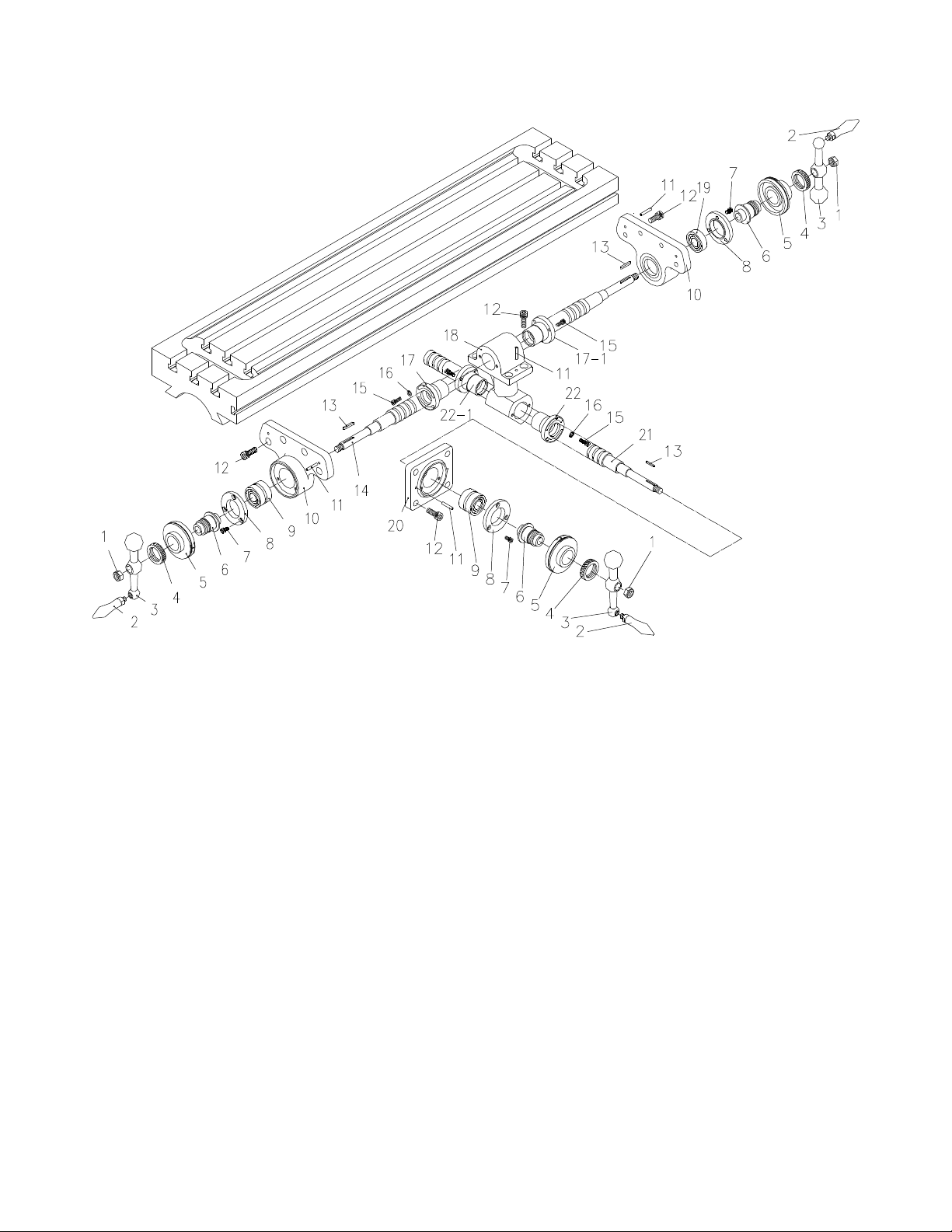
Lead Screw Assembly
Index No. P art No. Description Size Qty
1 ............... TS-0571052 ............ Jam Nut ............................................................. 1/2-20UNF .............................. 3
2 ............... LT-010C .................. Handle ............................................................... ............................................... 3
3 ............... LT-010B .................. Bal l Crank .......................................................... ..................................... .......... 3
................. LT-010BSP-CHR ..... Clutch Ball Crank (for powerfeed only) ............... chrome surface ...................... 3
................. LT-010BSP ............. Clutch Ball Crank (for powerfeed only) ............... .............................................. 3
4 ............... LT-009 .................... Dial Lock Nut ..................................................... ............................................... 3
5 ............... LT-008 .................... Dial .................................................................... ............................................... 3
6 ............... LT-007 .................... Dial Holder ......................................................... ............................................... 3
7 ............... TS-150301 .............. Hex Socke t Ca p Sc re w ...................................... M6 x 12 .................................. 9
8 ............... LT-005 .................... Bearing Retainer Ring ........................................ ............................................... 3
9 ............... BB-6204ZZ.............. Ball Bear ing ....................................................... ............................................... 3
10 ............. LT-002 .................... B earing Bracket ................................................. ............................................... 2
11 ............. LS-009 .................... Spring Pin .......................................................... 5 x 30 mm ............................... 8
12 ............. TS-1505031 ............ He x So ck e t Cap S cr e w ...................................... M 1 0 x 25 ............................... 1 6
13 ............. LS-014A .................. Key .................................................................... 3 x 3 x 25 mm ......................... 3
14 ............. MT-015D ................. Leadscrew ......................................................... ............................................... 1
15 ............. TS-1503041 ............ He x So ck e t Cap S cr e w ...................................... M 6 x 16 ................................ 1 0
16 ............. TS-1550051 ............ Washer .............................................................. M7 ......................................... . 4
17 ............. MT-019B ................. Feed Scr ew Nut ( set of 2; includes index # 17-1) ............................................... 1
18 ............. MT-017 ................... F eed Nut Bracket ............................................... ............................................... 1
19 ............. BB-6204ZZ.............. Ball Bearing ....................................................... ............................................... 1
20 ............. MT-025 ................... C ross Feed Bear ing Bracket .............................. ............................................... 1
21 ............. MT-024 ................... C ross Feed Sc r ew ............................................. ............................................... 1
22 ............. MT-022 ................... C ross F
eed Nut (set of 2; includes index # 17-22) .............................................. 1
36
Page 37
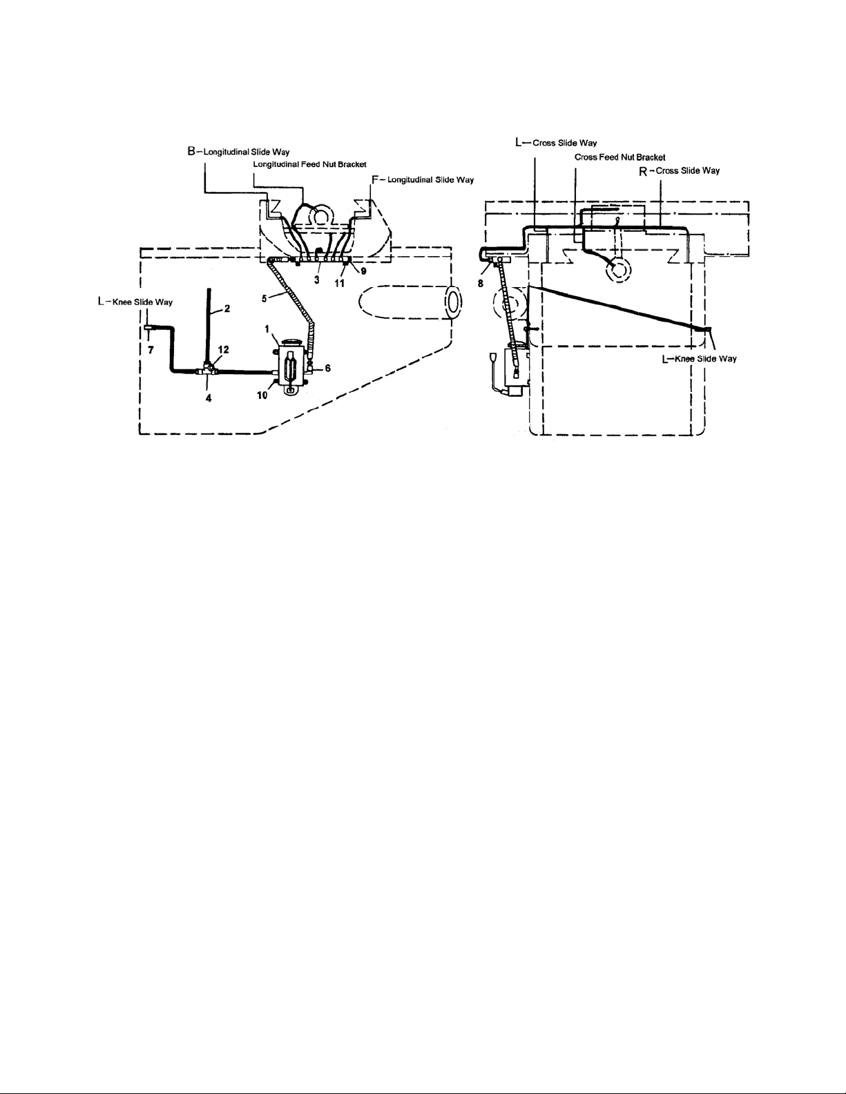
One-Shot Lubrication System
Index No. P art No. Description Size Qty
................. LT-8-A ..................... Hand Oil er Assembl y (i ncludes index #1,1A,4, 5, 9) ............................................ 1
1 ............... LT-8 ........................ Hand Oiler ......................................................... ............................................... 1
1A............. LT-8-SG .................. Hand Oiler Sight Glass (w/gasket)...................... ............................................... 1
2 ............... ALMP-04 ................. Aluminum Pipe .................................................. 3.5M ....................................... 1
................. ALMP-04-VS ........... Oil Line Set w/ Fittings ....................................... ............................................... 1
3 ............... DB-4 ....................... Oil Regulati ng Distributor ................................... ............................................... 1
4 ............... PKD-4 ..................... T-Join t ............................................................... ............................................... 1
5 ............... FHC-404 ................. Fle xib le Steel Tube ............................................ ............................................... 1
6 ............... PH-1-1/PB-4 ............ Check Joint ........................................................ ............................................... 2
7 ............... PH-4 ....................... Elbo w Joint ........................................................ ............................................... 2
8 ............... PA-4/PB-4 ............... Straight Joint...................................................... ............................................. 14
9 ............... PG-004 ................... Union ................................................................. .................................. ............. 1
10........JTM4VS-BUTW1458 ..... Screw ................................................................ ............................................... 4
11 ............. TS-1503061 ............ He x So ck e t Cap S cr e w ...................................... M 6 x 25 .................................. 2
12 ............. TS-1502061 ............ He x So ck e t Cap S cr e w ...................................... M 5 x 25 .................................. 1
37
Page 38

Electrical Connections – Single Phase only
38
Page 39

Electrical Connections – 3 Phase only
39
Page 40

427 New Sanford Road
LaVergne, Tennessee 37086
Phone: 800-274-6848
www.jettools.com
40
 Loading...