

Page 1
This .pdf document is bookmarked
Operating Instructions and Parts Manual
36-inch Metalworking Band Saw
Model VBS-3612
JET
427 New Sanford Road
LaVergne, Tennessee 37086 Part No. M-414470A
Ph.: 800-274-6848 Revision C2 03/2015
www.jettools.com Copyright © 2014 JET
Page 2

Warranty and Service
JET warrants every product it sells against manufacturers’ defects. If one of our tools needs service or repair, please
contact Technical Service by calling 1-800-274-6846, 8AM to 5PM CST, Monday through Friday.
Warranty Period
The general warranty lasts for the time period specified in the literature included with your product or on the official
JET branded website.
• JET products carry a limited warranty which varies in duration based upon the product. (See chart below)
• Accessories carry a limited warranty of one year from the date of receipt.
• Consumable items are defined as expendable parts or accessories expected to become inoperable within a
reasonable amount of use and are covered by a 90 day limited warranty against manufacturer’s defects.
Who is Covered
This warranty covers only the initial purchaser of the product from the date of delivery.
What is Co vered
This warranty covers any defects in workmanship or materials subject to the limitations stated below. This warranty
does not cover failures due directly or indirectly to misuse, abuse, negligence or accidents, normal wear-and-tear,
improper repair, alterations or lack of maintenance. JET woodworking machinery is designed to be used with Wood.
Use o f these ma chin es in t he pro cessing of metal , pl astics, or oth er m aterials outsid e recommen ded guidelines may
void the warranty. The exceptions are acrylics and other natural items that are made specifically for wood turning.
Warranty Limitations
Woodworking products with a Five Year Warranty that are used for commercial or industrial purposes default to a
Two Year Warranty. Please contact Technical Service at 1-800-274-6846 for further clarification.
How to Get Technical Support
Please contact Technical Service by calling 1-800-274-6846. Please note that you will be asked to provide proof
of initia l p u rch a s e whe n calling. If a product requires further inspection, the Technical Service representative will
explain and assist with any additional action needed. JET has Authorized Service Centers located throughout the
United States. For the name of an Authorized Service Center in your area call 1-800-274-6846 or use the Service
Center Locator on the JET website.
More Informa tion
JET is constantly adding new products. For complete, up-to-date product information, check with your local distributor
or visit the JET website.
How S tate Law A pplies
This warranty gives you specific legal rights, subject to applicable state law.
Limitations on This Warranty
JET LIMITS ALL IMPLIED WARRANTIES TO THE PERIOD OF THE LIMITED WARRANTY FOR EACH PRODUCT.
EXCEPT AS STATED HEREIN, ANY IMPLIED WARRANTIES OF MERCHANTABILITY AND FITNESS FOR A
PARTICULAR PURPOSE ARE EXCLUDED. SOME STATES DO NOT ALLOW LIMITATIONS ON HOW LONG AN
IMPLIED WARRANTY LASTS, SO THE ABOVE LIMITATION MAY NOT APPLY TO YOU.
JET SHALL IN NO EVENT BE LIABLE FOR DEATH, INJURIES TO PERSONS OR PROPERTY, OR FOR
INCIDENTAL, CONTINGENT, SPECIAL, OR CONSEQUENTIAL DAMAGES ARISING FROM THE USE OF OUR
PRODUCTS. SOME STATES DO NOT ALLOW THE EXCLUSION OR LIMITATION OF INCIDENTAL OR
CONSEQUENTIAL DAMAGES, SO THE ABOVE LIMITATION OR EXCLUSION MAY NOT APPLY TO YOU.
JET sells through distributors only. The specifications listed in JET printed materials and on official JET website are
given as general information and are not binding. JET reserves the right to effect at any time, without prior notice,
those alterations to parts, fittings, and accessory equipment which they may deem necessary for any reason
whatsoever. JET
Product Listing with Warranty Period
90 Days – Parts; Consumable items; Light-Duty Air Tools
1 Year – Motors; Machine Accessories; Heavy-Duty Air Tools; Pro-Duty Air Tools
2 Year – Metalworking Machinery; Electric Hoists, Electric Hoist Accessories; Woodworking Machinery used
for industrial or commercial purposes
5 Year – Woodworking Machinery
Limited Lifetime – JET Parallel clamps; VOLT Series Electric Hoists; Manual Hoists; Manual Hoist
Accessories; Shop Tools; Warehouse & Dock products; Hand Tools
NOTE: JET is a division of JPW Industries, Inc. References in this document to JET also apply to JPW Industries,
Inc., or any of its successors in interest to the JET brand.
®
branded products are not sold in Canada by JPW Industries, Inc.
2
Page 3

Table of Contents
Warranty and Servic e .............................................................................................................................. 2
Table of Contents .................................................................................................................................... 3
Warning ................................................................................................................................................... 4
Introduction ............................................................................................................................................. 6
Specifica tions ................................................................................................................ .......................... 6
Features and Terminology ....................................................................................................................... 7
Unpac king ............................................................................................................................................... 8
Contents of the Shipping Container ...................................................................................................... 8
Installation and Assembly ........................................................................................................................ 9
Fence ......................................................................................................................... ......................... 9
Feed Screw.......................................................................................................................................... 9
Shear ................................................................................................................................................... 9
Circle Cutting Attachment ..................................................................................................................... 9
Grounding Inst r uc tions ........................................................................................................................... 10
Extension cords ................................................................................................................................. 10
230 Volt, Three Phase Operation ....................................................................................................... 10
Converting from 230 V olt t o 460 V olt (Thr ee P hase) ........................................................................... 11
Three-Phase Test Run ....................................................................................................................... 11
Adjustments ................................................................................................................... ....................... 1 1
Blade Removal and Installation .......................................................................................................... 11
Blade Tension .................................................................................................................................... 12
Blade Tracking ................................................................................................................................... 12
Guide Post ......................................................................................................................................... 13
Blade Guides ..................................................................................................................................... 13
Squaring Wor k Table with Blade ........................................................................................................ 14
Auxiliar y Ta b le ............................................................................................................... .................... 1 4
Replacing Drive Belts ......................................................................................................................... 14
Work Lamp Bulb ................................................................................................................................ 15
Band Saw Operation.............................................................................................................................. 15
Blade Break-In P r oc edur e .................................................................................................................. 15
Setting Blade Speed .......................................................................................................................... 15
Evaluating Cutting Efficiency .............................................................................................................. 16
Welder Ope r a t io n .............................................................................................................. .................... 1 6
Shearing ............................................................................................................................................ 16
Removing Teeth................................................................................................................................. 17
Welding ....................................................................................................................... ...................... 1 7
Annealing ........................................................................................................................................... 18
Blade Selecti on ..................................................................................................................................... 19
Width ................................................................................................................................................. 19
Gage.................................................................................................................................................. 20
Pitch ......................................................................................................................... ......................... 20
Shape ................................................................................................................................................ 20
Set ..................................................................................................................................................... 21
Material .............................................................................................................................................. 21
Blade Breakage ................................................................................................................................. 21
Speed and Pitch Chart ........................................................................................................................... 23
Typical Band Saw Operat ions ................................................................................................................ 24
Troubleshooting – Mechanical and Electri c al P r oblem s .......................................................................... 26
Replacement Parts ................................................................................................................................ 29
Parts List: VBS- 3612 B and S aw ......................................................................................................... 30
Optional Accessories ......................................................................................................................... 34
VBS-3612 Band Saw ......................................................................................................................... 35
VBS-3612 Band Saw ......................................................................................................................... 36
Parts List: Welder, Shear and Work Lamp Assemblies ....................................................................... 37
Welder, Shear and Work Lam p Assembli es ........................................................................................ 39
Electri c al Connec tions – 3Ph, 230/460V ................................................................................................ 40
Electri c al Connec tions – 3Ph, 230/460V ................................................................................................ 41
Electrical Bo x................................................................................................................. ........................ 4 2
3
Page 4

Warning
1. Read and understand the ent ire owner’s manual befor e att em pting assembly or operation.
2. Read and understand the warnings po sted on the m achine and i n thi s manual. Fail ure to comply wit h
all of these warnings m ay cause seriou s i njury.
3. Replace the warning labels if they become obscured or remov ed.
4. This band saw is designed and i ntended for use by proper ly trai ned and ex peri enced personnel onl y.
If you are not familiar with the proper and safe operation of a band saw, do not use until proper
training and knowledge have been obtained.
5. Do not use this band saw for other than its intended use. If used for other purposes, JET discl aims
any real or implied warrant y and holds itself harmless from any injury that may result from that use.
6. Always wear approv ed safety glasses/face shields whil e using this band saw. Everyday eyeglasses
only have impact resi stant lenses; they are not safety glasses.
7. Before operating this band saw, remove tie, rings, watches and other j ewelry, and roll sleeves up past
the elbows. Remove all loose cl othing and c onfine long hair. Non- sli p footwear or anti- skid floor stri ps
are recommended. Do not wear gloves.
8. Wear ear protector s (plugs or muffs) during ext ended peri ods of oper ation.
9. Some dust created by power sanding, sawing, grinding, drilling and other construction activities
contain chemi cals known to cause cancer , bir th defects or other r eproductiv e harm . Some exampl es
of these chemic als are:
• Lead from lead based paint.
• Crystalli ne sil ic a from bricks, cement and other m asonry pr oduc ts.
• Arsenic and chromium from chemically treated lumber.
Your risk of exposure varies, depending on how often you do this type of work. To reduce your
exposure to these chemicals, work in a well-ventilated area and work with approved safety
equipment, such as face or dust masks that are specifically designed to filter out microscopic
particles.
10. Do not operate this machi ne while tired or under the influence of drugs, alcohol or any medicati on.
11. M ak e c er tain the switch is in the OFF position before connecting the machine to the power supply.
12. M ak e c er tain the machine is properl y grounded.
13. M ak e all machine adjustments or maintenance with the machine unplugged from the power source.
14. Remove adjusting keys and wrenches. Form a habit of checking to see that keys and adjusting
wrenches are removed from the machine before turning it on.
15. Keep safety guards in place at all times when the machi ne is in use. If removed for maintenance
purposes, use extreme caution and replace the guards immediately.
16. Check damaged parts. Before further use of the machine, a guard or other part that is damaged
should be carefully checked to determine that it will operate properly and perform its intended
function. Chec k for alignment of moving par ts, binding of moving parts, breakage of parts, mounting
and any other conditions that may affect its operation. A guard or other part that is damaged should
be properly repaired or replaced.
17. P r ov ide for adequate space surrounding work area and non-glar e, overhead lighting.
18. K eep the floor around the machi ne cl ean and fr ee of scrap material, oil and grease.
19. K eep v isitors a safe distanc e from the work area. Keep children away.
20. M ak e y our workshop child proof wit h padloc k s, m aster switches or by removing start er k ey s.
4
Page 5

21. Giv e your work undivi ded attention. Looki ng around, carryi ng on a conversati on and “horse-play” ar e
careless acts that can r esul t in serious injury.
22. Maintain a balanced stance at all times so that you do not fall or lean against the blade or other
moving part s. Do not over r eac h or use excessive force to perform any mac hine operation.
23. Use the ri ght t ool at the cor rect speed and feed r ate. Do not for ce a tool or attachment to do a job for
which it was not designed. T he ri ght tool will do the job better and safer.
24. Use recom mended accessories; i mproper accessories m ay be hazar dous.
25. Mai ntain tools with care. Keep bl ades sharp and clean for the best and saf est performance. Follow
instructions for lubricating and changing accessories.
26. Turn off the machine bef ore cleaning. Use a brush or compressed air t o remove chips or debris — do
not use your hands.
27. Do not stand on the machine. Seri ous i nj ur y c ould oc c ur if the mac hi ne tips over.
28. Never leave the machine r unning unatt ended. Turn the power off and do not leave t he machine until
the blade comes to a complet e stop.
29. Remove loose items and unnecessary work pieces from the area bef or e start ing the machine.
30. Never place hands directly in line with the saw blade.
31. A lways use push sticks when cutting small material.
32. Raise or lower the blade guide only when the machine has been turned off and the blade has stopped
moving.
33. Al ways wear leather gloves when handling sa w blades. The operator should not wear gloves when
operating the machine.
34. Do not allow the saw blade to rest against the workpiece when the saw is not running.
35. The saw must be stopped and the el ectrical supply must be cut off before any blade r eplacement,
drive belt repl ac em ent, or any periodic service or maintenance i s performed on the machine.
36. Remov e cut off pieces caref ully, keeping hands a way from the blade. T he saw must be stopped and
the electrical suppl y c ut off or machine unplugged before reaching into the cutting ar ea.
Familiariz e you rself with the following safety no tices used in this manual:
This means that if precautions are not heeded, it may result i n minor injury and/or
possible machine damage.
This means that if precautions are not heeded, it may result i n serious injury or possibly
even death.
- - SAVE THESE INSTRUCTIONS - -
5
Page 6

Introduction
This manual is provided by JET covering the safe operation and maintenance procedures for a JET
Model VBS-3612 Band Saw. This manual contains instructions on installation, safety precautions, general
operating proc edures, maintenance i nstructions and part s breakdown. This m achine has been designed
and constructed to pr ovi de years of troubl e free operation if used in accor dance wit h instructi ons set fort h
in this manual. If there are any questions or comm ents, please contact either your local supplier or JET.
JET can also be reached at our web site: www.jettools.com.
Specifications
Model Number ........................................................................................................................... VBS-3612
Stock Number................................................................................................................................ 414470
Blade Speeds (SFP M) .................................................................................... Low 50-410; High 540-4925
Height Capacity , M aximum (in.) ............................................................................................................. 12
Throat Capacit y , Maximum (in.) ............................................................................................................. 36
Table Size, Main (L x W)(in.)............................................................................................... 23-5/8 x 27-1/2
Table Size, Auxiliary (L x W)(in.) ......................................................................................... 17-3/4 x 27-1/2
Table Height at 90° (in.) ......................................................................................................................... 40
Table Tilt (deg.) ...................................................................................................................... 10° L, 45° R
Welder (KVA) ....................................................................................................................................... 4 .2
Blade Length, approx. (in.) .............................................................................................. 195-1/4 – 198-1/4
Blade Width (in.) ............................................................................................................... 1/8 min., 1 ma x.
Motor ........................................................................... TEFC, 3HP, 3Ph, 230/460V (pr ewir ed 230V ), 60Hz
Floor Space Requi r ed ( LxWx H) (in.) ........................................................................................ 69 x 32 x 81
Net Weigh t (lb s.) ............................................................................................................................... 1,760
The above specifications were current at the time this manual was published, but because of our policy of
continuous impr ovement, JET reserves the right to change specificati ons at any tim e and without prior
notice, without incurring obligati ons.
6
Page 7
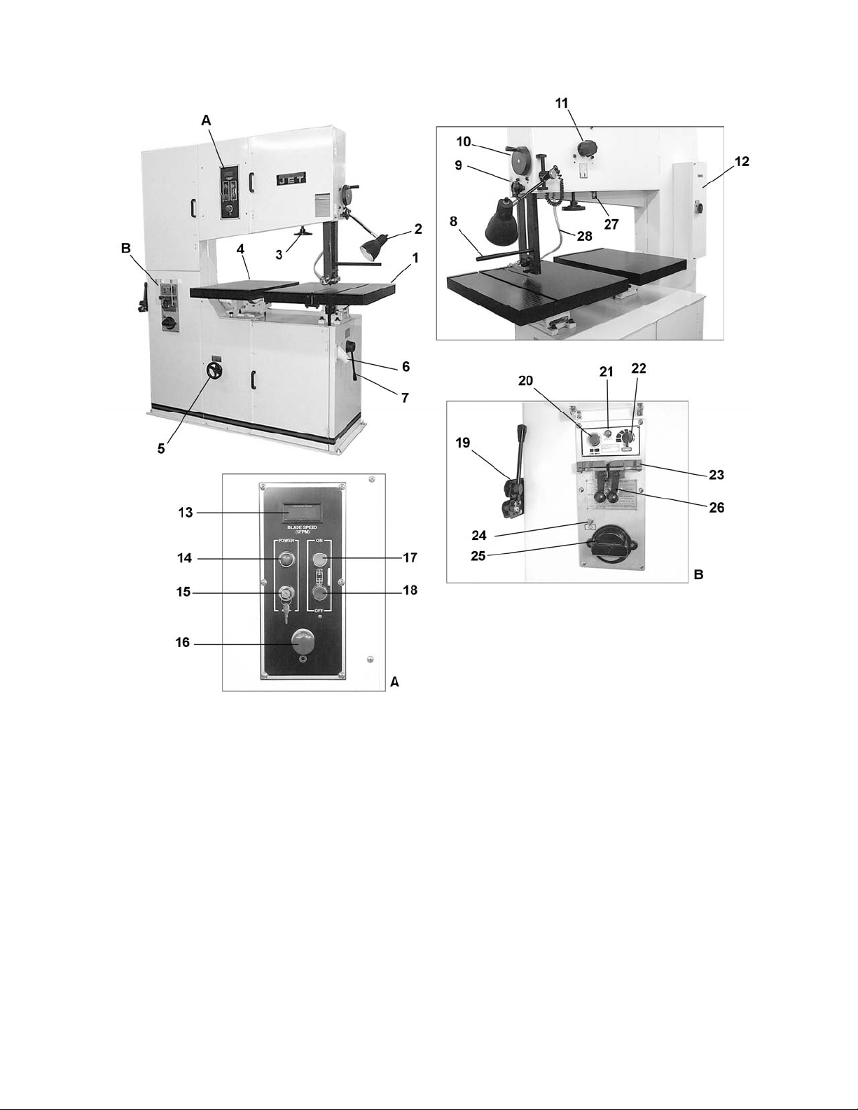
Features and Terminology
1 – Main Work Table
2 – Work Lamp
3 – Blade Tension Handwheel
4 – Auxiliary Work Table
5 – Variable Speed Handwheel
6 – Chip Port
7 – Gear Shift Lever
8 – Rod for Circle Cutting Attachment
9 – Guide Post Lock Knob
10 – Guide Post Raise/Lower Handwheel
11 – Blade Tracking Knob
12 – Electrical box
13 – Blade Speed readout (SFPM)
14 – Power Indicator Light
15 – Control Panel Loc k out
16 – Emergency Stop Button
17 – Blade Start Button
18 – Blade Stop Button
19 – Shear
20 – Weld Switch
21 – Anneal Switch
22 – Clamp Pressure Selector
23 – Clamp Jaws
24 – Grinding Wheel Swit c h
25 – Grinding Wheel
26 – Clamp Handles
27 – Blade Tension Gauge
28 – Chip Blower Hose
7
Page 8
Unpacking
Open shipping cont ainer and check f or shipping
damage. Report any damage immediately to
your distributor and shipping agent. Do not
discard any shippi ng material until the Band Saw
is set up and running properly.
Compare the content s of your container with the
following parts list to make sure all parts are
intact. Mi ssing parts, if any, should be reported
to your distributor. Read the instruction manual
thoroughly for assembly, maintenance and
safety instructions.
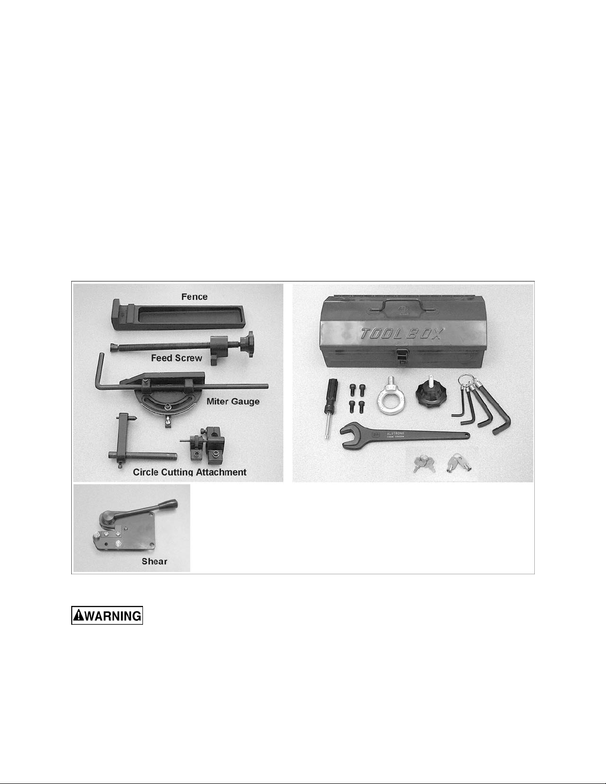
Contents of the Shipping Container
1 Band Saw
1 Fence
1 Feed Screw
1 Miter Gauge
1 Circle Cutting Attachment
1 Shear
1 Tool box, cont aining:
1 Reversible Screwdriver
2 Socket Head Cap Screws, 5/16” x 1”
2 Socket Head Cap Screws, 5/16” x 5/ 8”
1 Eye Bolt
1 Knob
1 Set of Hex Wrenches
1 Wrench, 26mm
1 Set of Keys for control panel
1 Set of Keys for rear door
1 Owner's Manual
1 Warranty Card
Read and understand the entire contents of this manual before attempting set-up
or operation! Failure t o co mply may cause serious injury.
8
Page 9
Installation and Assembly
Tools requi red for assemb ly:
Forklift with strap or chain
Eye bolt (provided)
Set of hex wrenches (provided)
Remove all crati ng and plastic from ar ound the
band saw. Remove any lag screws or holding
straps which secure t he band saw to the wood
pallet.
Remove the eye bolt from the tool box, and
screw it into the hole at the top of the machine.
Use a forklift with a strap or chain c onnected to
the eye bolt to lift the band saw fr om the pallet.
Move the band saw to its permanent location
which should be dry, well ventilated, with
sufficient lighting. Leave enough space on all
sides to handle long stock or perform routine
maintenance on the machine. Make sure the
floor is level and able to support the weight of
the machine.
The Band Saw may be further stabilized by
securing it to the floor using lag screws through
the four holes in t he stand.
Areas of the Band Saw have been given a
protectiv e coating at the fact ory. This should be
removed with a soft cloth moistened with
kerosene or mi neral spirits. Do not get solvents
near plastic or rubber part s, and do not use an
abrasive pad as it may scratc h m etal surfaces.
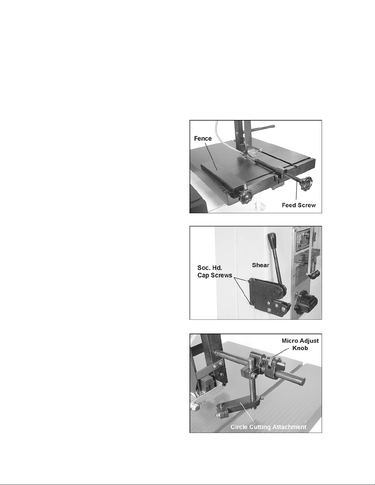
Fence
Place the f ence (Figure 1) onto the groove in the
table as shown, and scre w in the k nob (f rom the
toolbox) to tighten the fence in position.
Feed Screw
Use two socket head cap screws (provided) to
mount the feed screw to the front edge of the
table (Figure 1). Use a 6mm hex wrench to
tighten the screws.
Shear
Mount the shear to the back edge of the band
saw with two socket head cap screws
(provided), as shown in Figure 2.
Figure 1
Figure 2
Circle Cutting Attachment
To use the circle cutting attachment , mount it to
the rod as shown in Figur e 3.
Figure 3
9
Page 10

Grounding Instructions
Electrical connections must
be made by a qualified electrician in
compliance with all relevant codes. This
machine must be properly grounded to help
prevent electrical shock and possible fatal
injury.
This machine must be grounded. I n the event of
a malfunction or breakdown, groundi ng provides
a path of least r esistance f or electric current to
reduce the ri sk of el ectri c shock .
Improper connection of the equipmentgrounding conductor can result in a risk of
electric shock. The conductor with insulation
having an outer surface that is green with or
without yellow stripes, is the equipmentgrounding conduct or. If repair or replac ement of
the electric cord or plug is necessary, do not
connect the equipment-groundi ng conduct or to a
live terminal.
Check with a qualified electrician or service
personnel if the grounding instructions are not
completely understood, or if in doubt as to
whether the tool is properly grounded.
Repair or replace a damaged or worn cord
immediately.
Make sure the voltage of your power supply
matches the specif ications on the m otor plate of
the Band Saw. The machine should be
connected to a dedicated circuit.
Extens ion cords
Recomm end ed Ga ug es (A WG ) of Extensi on Co rd s
Extension Cord Length *
25
50
75
100
150
200
Amps
feet
feet
feet
feet
feet
feet
The use of an extension cord is not
recommended for this Band Saw. But if one is
necessary, m ake sure the cord rati ng is suitable
for the amperage listed on the machi ne’s motor
plate. An undersized cord will cause a drop in
line voltage resulting in loss of power and
overheating.
Use the chart in Fi gure 4 as a general guide in
choosing the correct size cord. If in doubt, use
the next heavi er gauge. The smaller the gauge
number, the heavier the cord.
230 Volt, Three Phase Operation
The three-phase model i s factory wired f or 230
volt, but can be converted to 460 volt if so
desired (see “Converting From 230 Volt to 460
Volt”). You may either install a plug or “hardwire” the Band Saw direc tly to a control panel.
If you are connec ting a plug, use a proper ULlisted plug suitable for 230 volt operation.
< 5 16 16 16 14 12 12
5 to 8 16 16 14 12 10 NR
8 to 12 14 14 12 10 NR NR
12 to 15 12 12 10 10 NR NR
15 to 20 10 10 10 NR NR NR
21 to 30 10 NR NR NR NR NR
*based on li miting th e lin e vol tage drop to 5V at 15 0% of the
rated amp eres.
NR: Not Recommended.
Figure 4
10
Page 11
If the Band Saw is to be hard- wired to a panel,
make sure a disconnect is available for the
operator. During hard-wiring of the Band Saw,
make sure the fuses hav e been removed or the
breakers have been tripped in the circuit to
which the Band Saw will be connected. Place a
warning placard on the fuse holder or circuit
breaker to prevent it being turned on while the
machine is being wired.
Converting from 230 Volt to 460 Volt (Three Phase)
To convert from 230 volt to 460 volt:
1. In t he band saw’s electri cal box, change the
setting on the dial of the overload relay
(“FR” on page 42).
2. All re-wiring is done in the electrical box
only, by moving the j umpers at the terminal
block. Re-connect jumpers from 230V to
460V positions as shown in the diagram
inside the electrical box. (The diagram is
also incl uded in the back of t his manual.)
3. If using a plug, install a proper UL-listed
plug suitable for 460 volt operation.
IMPORTANT: Consult the diagrams on pages
40-42 for any clarification of these changes on
230V to 460V conversi on.
Three-Phase Test Run
After wiring the band saw, you should check that
the wires have been connected properly.
Connect machi ne to the power source and turn
it on for an instant to watch the direction of blade
moveme nt.
If the blade runs upward instead of downward,
disconnect machine from power, and switch
any two of the three leads in the motor junction
box (see “Elect ri c al Connec tions”, page 40).
Adjustments
Blade Removal and Installation
Wear leather gloves when
removing or in stalling band saw blades. New
blades usuall y come in a coiled position ; to
prevent inj ury, hold the blad e with one hand
while carefully uncoiling it with the other.
1. Disconnect machine from power source.
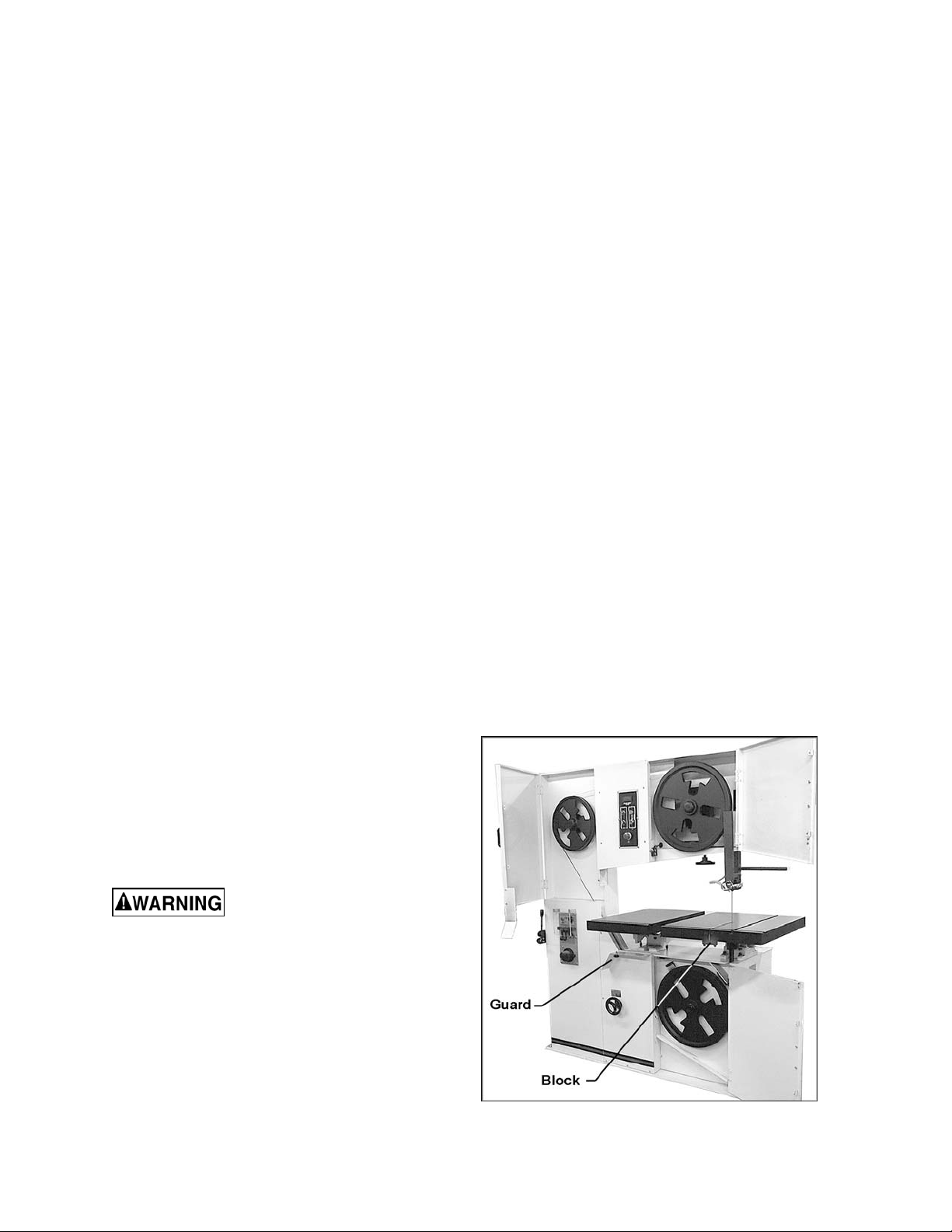
2. Open t he upper and lower doors, and swing
away the guard (Figur e 5) .
3. Remove the block from the f ront edge of t he
table (Figure 5).
Figure 5
11
Page 12
4. Loosen tension on the blade by turning t he
tension handwheel (Figure 6) to the left.
5. Remove the worn blade and install the new
blade, making sure the teet h face downward
where they pass through the slot in the
table.
6. Use the tension handwheel to tighten the
tension on the bl ade.
7. Proceed with “Blade Tension” and “Blade
Tracking” bef or e oper ating the band saw.
Blade Tension
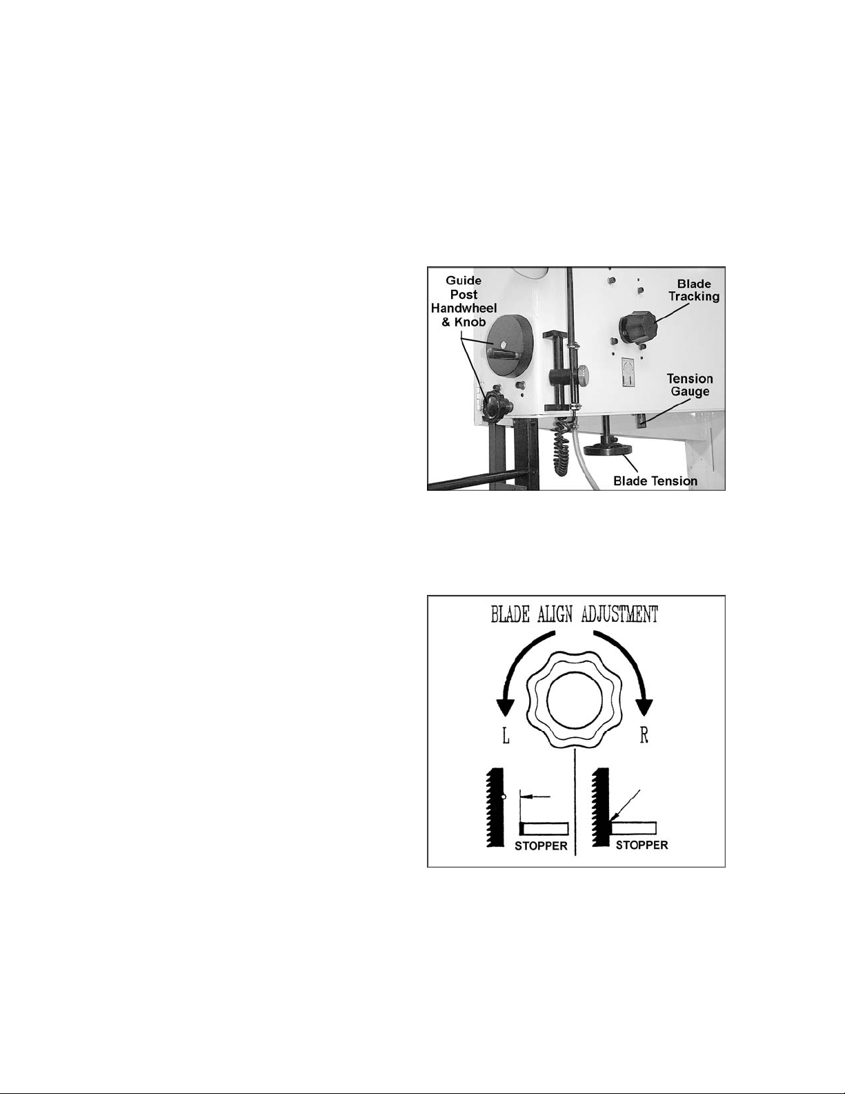
Rotate blade tension handwheel to the right to
increase tension on the blade, to the left to
decrease tension on the blade. Initially, set the
blade tension t o correspond to the width of your
blade, as indicat ed on the tension gauge (Figur e
6). As you become familiar with the saw, you
may find it necessary to change the blade
tension from the initi al setting, depending on t he
width of the blade as well as the material being
worked.
Keep in mind that too much or too little blade
tension can cause blade breakage and/or poor
cutting perf ormance.
If the band saw is not t o be used f or a period of
time, release tension on the blade – this will
prolong it s life. First make a note of the specif ic
tension setting for that blade. The tension can
then be re-established quickly when operations
are resumed.
Blade Tracking
1. Disconnect machine from power source.
Figure 6
2. Open the top blade wheel doors.
3. Move the gear shift lever into neutral
position (str aight down).
4. Move the upper and lower blade guides
away from the blade ( see “Blade Guides”).
5. Rotate upper blade wheel by hand,
observing the position of the blade as it
rides upon the wheel. The blade should
track as near the center of the wheel as
possible.
6. If the blade does not track properly, rotate
the blade tracking knob (Figure 6) clock wise
to move the blade toward the front of the
wheel (as vi ewed from the front of the saw)
or counterclockwise to move the blade
toward the rear of the wheel. NOTE: This
will also move the blade away from or
toward the stoppers on the blade guide
assemblies, as shown i n Figure 7.
Figure 7
12
Page 13
IMPORTANT: These are sensitive
adjustments; make them gradually and
allow the blade tim e to reac t t o the changes.
7. When satisfied, return the upper and lower
blade guides cl ose to the blade.
8. Close upper and lower doors.
Guide Post
For effectiv e cutting and for safety’s sake, ther e
should be a minimum amount of space between
the top of the workpiece and the bott om of the
blade guides. Loosen the locking knob (see
Figure 6) and r otate the handwheel ( Fi gure 6) to
raise or lower the guide post so that the guides
clear the workpiece by about 3/16”.
Blade Guides
Blade guides must be
properly adjusted or damage may occur to
the blade and/o r guides.
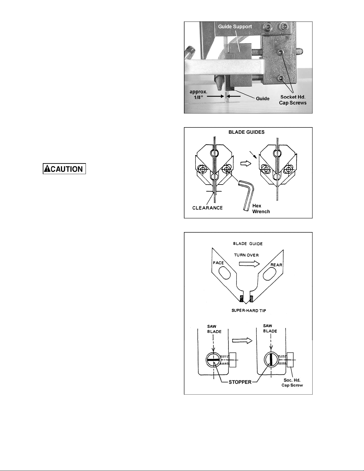
1. Loosen the two socket head cap screws on
the guide housing. S ee Figure 8.
Figure 8
2. Move the guide support forward or
backward in accordance with the width of
the blade. The front end of the blade guides
should be adjusted approximately 1/8”
behind the blade teeth. See Figure 8.
3. Tighten the hex c ap screws securel y .
4. This procedure should be done for both
upper and lower guide housings.
5. Loosen the socket head c ap screws (Figure
9) on the blade guides.
6. Move the blade guides so they are as close
to the blade as possible without touching it.
7. Ti ghten the socket head c ap screws (Fi gure
9).
8. This procedure should be done for both
upper and lower blade gui des.
As the blade guides receive use, they will
become worn at the front end. If the blade
guides become dif ficult to adjust, switch the l eft
and right blade guides (Figure 10).
The stopper posit ioned behi nd the back edge of
the blade (Figure 10) will also become worn with
use, and the friction of the shaft with the saw
blade may cause lines in the surface of the
stopper. If this occurs, loosen the socket head
cap screw, and rotate the stopper to either side
to change its position on the blade. Re-tighten
socket head cap screw.
Figure 9
Figure 10
13
Page 14
Squaring Work Table with Blade
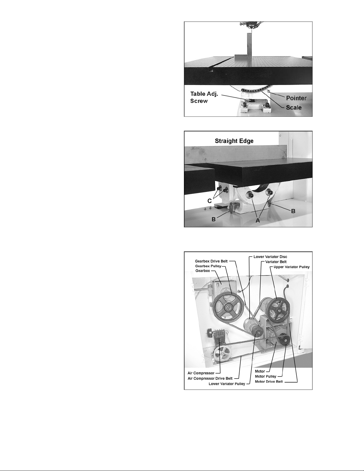
1. Place the table in horizontal posi ti on with “0”
on the scale (Figur e 11) .
2. Pl ace a machini st’s square on the tabl e and
against the bl ade as shown.
3. If the square is not flush against t he blade,
loosen the screw below the table (Figur e 11)
with a 26mm wrench (provided).
4. Tilt the table as needed until the square is
flush with bl ade. Reti ghten the screw.
5. Make sure the pointer is set at “0” on the
scale. If it needs slight adjustment, loosen
the screw and shif t the pointer until it ali gns
with “0”. Re-tighten the screw.
Auxiliary Table
1. After the main work table has been set
perpendicular to the blade, use a straight
edge to confirm that the auxiliary table is
level with the main table, as shown in Figure
12. If the auxil iary table is not l evel with the
main table, make adjustments as follows.
2. To tilt the auxiliary table lef t or right, loosen
the screws (A, Figure 12) and turn one of
the stops (B, Figure 12) as needed. Retighten screws (A, Figure 12) securely after
adjustment.
3. To adjust the table front to back, loosen
screws (C, Figure 12). Re-tighten screws
securely after adjustment.
Replacing Drive Belts
(See Figure 13)
Figure 11
Figure 12
1. Disconnect machine from power source.
2. To remove the mo to r dri ve b elt , loosen the
four screws at the ba se of the mot or. Lift up
on the motor to slacken and remove the
belt.
3. To r emove the air compressor drive belt,
loosen the four hex nuts on the base of the
air compressor and sl ide the compressor in
the dir ection of t he motor. After instal ling a
new belt, slide the compressor away from
the motor to tension the belt, and re-tight en
the four hex nut s.
4. To remove the gearbox drive belt, l oosen
the hex nuts on the base of the lower
variator, and sl ide the lower v ariator upward
to slacken and remov e the belt .
5. To remove the variator belt, loosen the four
hex nuts on the variator and push the
variator upward to slack en the belt.
Figure 13
14
Page 15

6. After installing new belts, make sure they
are tensioned properly.
Work Lamp Bulb
The Work Lamp uses a 20W/120V halogen
bulb.
Band Saw Operation
Consult “Features and Terminology” on page 7
for identification of the controls.
Unlock the control panel using the provided
keys.
Never operate the band saw
without blade co vers in place and secured.
Blade Break-In Procedure
New blades are v ery sharp and, ther efore, have
a tooth geometry that is easily damaged if a
careful break-in procedure is not followed.
Consult the blade manufacturer’s literature for
break-in of specific bl ades on specific material s.
The following procedure will be adequate,
however, for br eak-in of JET-suppli ed blades on
lower alloy ferrous materials.
1. Use a section of round stock.
2. Operate t he saw at low speed. Start the cut
with a very light feed rate.
3. When the saw has completed about 1/3 of
the cut, increase the feed rate slightly and
allow the saw to complete the cut.
4. Keep the feed r ate at the same setting and
begin a second cut on the same or similar
workpiece.
5. When the saw has completed about 1/3 of
the cut, increase the feed rate while
watching the chip formati on until cutting is at
its most efficient rate (refer to “Evaluating
Cutting Efficiency” below). Allow the saw to
complete the cut.
6. The blade is now considered ready for use.
Setting Blade Speed
1. Refer to the Speed and Pitch selection c hart
on page 23. Select t he speed setting for the
material to be cut.
2. While the machine is NOT running, move
the gear shift lever to the required speed
setting (high or low). See Figure 14.
Move the gear shift lever
only when the machine is NOT running, to
prevent damage to the gearbox.
Figure 14
15
Page 16

3. Start the saw using the pushbutt on.
4. Turn the speed setting handwheel (Figure
14) to the required speed. Turning the
handwheel clockwise increases speed.
Turning counterclockwise decreases speed.
Rotate the speed setting
handwheel only when the band saw is
running.
Evaluating Cutting Efficiency
The best way to determine whether the blade is
cutting effi ciently is to observe the chi ps formed
by the cutting.
• If the chip formation is powdery, then the
feed is much too light, or the blade is dull.
• If the chips f ormed are curled, but c olored –
blue or straw colored from heat generated
during the cut – then the feed rate is too
high.
• If the chips are slightly curled and are not
colored by heat – the blade is sufficiently
sharp and is cutti ng at it s most efficient rate.
Welder Operation
Wear eye protection while
operating the welder. Use care when
handling the blade after welding to avoid
burns.
The welding procedure involves the following
steps: Shearing the blade, grinding teeth to
allow for the weld area, the actual welding,
inspection of t he blade, annealing, grinding and
a final inspection of the blade. This procedure
can be accomplished using the shear and
welder assembli es on your band saw. Proceed
as follows:
Shearing
Cut the blade to the longest length needed for
the band saw. Using the shear to cut your blade
will ensure that the blade ends are cut flat,
square and smooth.
1. Place the blade in the shear as shown in
Figure 15. Make sure the blade is held
square with the shear knif e, so that the cut
will be square with the blade.
Figure 15
2. Posit ion the blade so that the cut is made at
a place that allows for uniform spacing of
the teeth. See Fi gur e 16.
3. Push down the handle.
Figure 16
16
Page 17

IMPORTANT: If a blade has been cut by usi ng
snips, the ends of the blade must be ground
square before weldi ng them together, as shown
in Figure 17.
Removing Te eth
In fine pitched blades, one or more of the teeth
on each side of the cut may need to be removed
by grinding so t hat the weld area of the blade i s
uniform and t he teeth will be uniformly spaced.
See Figure 16.
Welding
4. Carefully cl ean the ends of the blade which
will contact the welder jaws. Remove any
dirt, oil, scale and oxide.
Any rust (oxide) on the blade
in the vicinity of the weld must be ground off
before the blade can be welded.
5. Turn pressure knob to “0” position (pointed
downward). NOTE: There will be some
resistance when turning the knob.
6. Insert one end of the blade in the left clamp
(Figure 18). Position the back edge of the
blade against the back edge of the left
clamp. Then position the end of the blade
midway between the left and right clamps.
Tighten the left clamp.
7. Insert t he other end of the blade in the right
clamp. Positi on the back edge of the blade
against the back of the right clamp. Then
butt the end of the blade against the other
end of the blade (the blade ends need to be
in contact with each other). Tighten the ri ght
clamp.
8. Set the pressure selector switch
(counterclockwise rotation) to the
approxim ate setting required for the width of
the blade being wel ded.
Figure 17
Figure 18
Keep hands cl ear of the weld
area and the clamp jaws during welding.
9. Press and hold t he weld button (Fi gure 18).
When the weld button is pushed, the left
clamp moves to t he right to apply pressure
to the blade ends. At the same time, sparks
will come from the blade ends as they are
being welded. Do not release weld button
until the blade joint is “red hot.”
10. Release the weld button, and wait 3 or 4
seconds until blade returns to original c olor.
Unclamp the blade.
11. Rotat e the pressure selector switc h back to
“0”.
17
Page 18

The welder is designed for
intermittent use. Repeated welding within a
short period of time may cause the welder to
overheat.
12. Remove the blade from the clamps, and
carefully i nspect it. The spacing of the teeth
should be uniform and the weld should be
located in the center of the gullet.
Misalignment is easily noted at this time
from the weld appearance. See Figure 19
for examples of incorrect welds.
13. If the weld i s imperfect, ref er to the troubleshooting section on page 28 for possible
remedies to any problems. Make c or r ec tions
before anneali ng.
Annealing
The blade must now be annealed, or cooled at a
controlled rate to prevent it from becoming too
brittle.
14. Turn the pr essure selector knob all the way
to the left so the clamp jaws are cl osest to
each other.
15. I nsert the blade into the clamps so the weld
area is centered between the clamps.
Secure the blade in the jaws with the clamp
handles.
Figure 19
16. Quickly press and release (jog) the anneal
button (Figure 18). Repeat the press-andrelease process unt il you see a slightly red
glow from the weld area.
Do not press and hold the
anneal push button. The weld will be
overheated and will fail du e to the excessive
heat.
17. Rel ease both blade cl amps, allow the blade
to cool, then remove the blade from the
clamps.
18. Check the integrity of the weld. Bend the
blade to form a radius at the point of the
weld. The size of the radius should be
approxim ately the same as the radius of the
band saw driv e wheel. The weld must hol d
and not break or crack after forming the
radius. If the weld breaks, cut away the
welded area and repeat the weldingannealing process.
19. Check to make sure the welded section is
the same thick ness as the rest of the blade.
If not, grind off excess weld material using
the grinder ( Figure 20). Figure 21 i llustrates
some unacceptable grindings.
Figure 20
Figure 21
18
Page 19

If the blade is thicker at the
weld than at the rest of the blade, using the
blade may damage the guides.
20. W hen grinding, do not hit the teeth, or grind
deeper than the thickness of the blade; or
burn or overheat the weld area. Be sure to
remove flash from the back edge of the
blade. Any flash or “stub” teeth which
project beyond the normal set or height of
the other teeth must be ground off.
Clean Up
It is very important that the clamp j aws be kept
clean at all times. The jaws or inserts must be
wiped or scraped cl ean after every weld. Doing
this will ensure better welds by holding proper
alignment, preventing flash from becoming
embedded in the bl ade, and pr eventing shorts or
poor electri c al c ontact.
Blade Selection
Using the proper bl ade for the job will incr ease
the operating eff iciency of your band saw, help
reduce necessary saw maintenance, and
improve your pr oduc tivity. Thus, it is important to
follow certain guidelines when selecting a saw
blade. Blade break age, teeth stripping, crooked
cuts, and other com m on complai nts are, in most
instances, caused by usi ng the wrong blade.
Consider these fac tors when selecting a blade:
• The type of materi al y ou will be c utti ng.
• The thickness of the workpi ec e.
• The features of the workpiece, such as
bends or curves wit h small radii.
These factors are important because they
involve basic concepts of saw blade design.
There are six blade features that are normally
changed to meet certain sawing requirements:
1. width
2. gage
3. pitch (number of teeth per inch)
4. tooth form (or shape)
5. the “set” of the teeth
6. the blade material itself
Width
Band saw width is measured from the back of
the blade to the ti p of the tooth. Always use the
widest blade possible that still performs the
needed job. Generally, wider blades are used
for straight cutting. Narrower blades are used
when the part being cut has curves with small
radii. Refer t o the chart in Figure 22 to select a
width for radius cutting.
The rad ii in this chart ar e all b ased on cutting 1-inch th ick
mild steel and using manual feed. In order to cut a close
tolerance radius t h e f oll ow i ng factor s , in ad dition t o th e bl ade
width, must be considered: thickness, machinability, feed
force and the l ocation of the pi vot poi nt. Hea vy feed i n thic k
work, for example, results in a barrel-shaped cut.
Figure 22
19
Page 20

Gage
Use the standard gage ( blade thi ckness) except
when the increased thickness of the workpiece
decreases accuracy and width cannot be
increased to compensate.
Examples of heavy gage applications:
1. When radius cutting in thick materials.
2. When the maximum width usable on the
machine still provides insufficient beam
strength f or the blade. (Beam strength i s the
blade’s resistance to compression caused
by strong feeding or the type of material
being cut).
Pitch
Pitch is measured i n “teet h per inch” (T.P .I.) and
can be constant or variable. Figure 23 shows
blades with differ ent pitches. A fine pitch (more
teeth per inch) will cut slower but smoother. A
coarse pitch (fewer teeth per inch) will cut
rougher but faster.
As a rule of thumb, the thicker the workpiece,
the coarser will be the blade pitch. If you have to
cut a hard or very brittle material, you will
probably want to use a blade with a finer pitch in
order to get clean c uts.
Using a blade with too few teeth may cause
vibration and a r ough cut, while too many teeth
may cause the gullets to fill with shavings and
overheat the blade.
As a general rule, use a blade that will hav e no
fewer than 6 and no m ore than 12 teeth in the
workpiece at any given time.
The chart on page 23 will aid in determining
pitch for a particular job.
Shape
Figure 23
Figure 24 shows comm on types of tooth shape.
Tooth shape has an effec t on cutt ing rate.
The Regular blade, sometimes called a “raker”
blade, has evenly spaced teeth that are the
same size as the gullets, and a 0-degree rake
angle. This is a good general-purpose blade,
and often works well with ferrous metals.
The Skip type has fewer teeth and larger gullets,
providing the added chip clearance needed for
cutting softer, nonferrous materials, as well as
non-metalli c applications such as wood, plasti c,
cork, and composi tion materials.
The Hook blade has larger t eeth and gullet s and
a positive r ake angle which permits better feed
and chip removal. It is useful f or both cast iron
as well as hard, nonfer r ous all oy s.
Figure 24
20
Page 21

Variable-tooth blades combine features of the
other styles. They generally offer smooth cuts
and long blade life, while reducing noise and
vibration.
Set
The term “set” refers to the way in which the
saw teeth are bent or positioned. Bending the
teeth creat es a kerf that is wider than the back
of the blade.
Set patterns are usually selected depending
upon the type of material t hat needs to be cut.
Three common set pat terns are shown in F i gure
25.
The Regular, or Raker, set is generally furnished
on blades which have 2 to 24 teeth per inch.
These blades hav e one tooth set to left, one t o
right, and one unset tooth called a raker. The
raker set is oft en used for contour c utting.
The Wave set is generall y furnished on blades
which have 8 to 32 teeth per inch. This set has
groups of teet h bent alternately to left and right,
which reduces the strain on individual teeth.
Blades with a wave set are used where tooth
breakage is a problem, such as in cutting thin
stock or where a variety of work is cut without
changing blades; al so when the thickness of the
workpiece changes, such as cutting hollow
tubing or struc turals.
The Straight set has teeth in a consistent,
alternati ng pattern, which is good for fast, basic
cuts where a fine finish is not im portant. This set
is also popular f or cut ting wood and plastics.
Material
Some of the most common blade materials
include:
Carbon Steel Blade – widely used because of
its general adapt ability for all types of work and
for its lower cost. Excellent for cutting
nonferrous met als and plastics.
High Speed Steel Blade – resists heat
generated while cutting to a far greater extent
than carbon steel blades. B est suited for cutting
nonferrous metals.
Figure 25
Blade Breakage
Band saw blades are subject to high stresses
and breakage may sometimes be unavoidable.
However, many f actor s can be controlled t o hel p
prevent most blade breakage. Here are some
common causes for break age:
1. Misalignment of the blade guides.
2. Feeding workpiec e too quickly.
3. Using a wide blade to cut a short radius
curve.
4. Excessive tension.
5. Teeth are dull or impr oper ly set.
6. Upper guides are set too high off the
workpiece.
7. Faulty weld on bl ade.
Carbide-Tipped Blade – Best used for cutting
titanium, beryllium, and case hardened
materials.
21
Page 22

Maintenance
Before doing maintenance on
the machine, disco nnect it f rom the electri cal
supply by pulling out the plug or switching
off the main switch! Failure to comply may
cause serious inj ury.
Use a brush to loosen accumulated chips and
debris. Use a shop vacuum to remove the
debris. Make sure the chip brush on the lower
band wheel is properly adjusted.
Lubricate the air compressor with air tool oil
about every six months, or more frequently if
necessary. Unscrew the cap (Figure 26) and
add oil. Replac e cap when fi nished.
Add grease to the gear box through the grea se
fitting; also add grease as needed to the worm
gear.
If the power cord is worn, cut, or damaged in
any way, have it repl ac ed immediately.
Figure 26
The chart (Figure 27) identifies areas that
require cleaning and/or lubricating. Use good
quality, gener al pur pose l ubr icants.
Machine Part Lubricant Frequency
Bearings Machine oil Wipe down every day and
lubricate ev er y 6 mont hs
Rack and sliding portion of
Guide Post
Gear shift lever Grease every 6 months
Worm gear Grease every 3 months
Variator pull ey Machine oil every 3 months
Blade tension screw Grease once a month
Air compressor reservoir Air Tool oil every 6 months
Weld clamp jaws ------- clean after each use
Rubber tire ------- wipe off daily
Work tables ------- clean daily
Grease every 7 days
Figure 27
22
Page 23

Speed and Pitch Chart
23
Page 24

Typical Band Saw Operations
24
Page 25

Troubleshooting – Operating Problems
Trouble Probable Cause Remedy
Blade has been improper ly welded. Re-weld the blade (see page s 16-19).
Saw blade is twisted.
Cuts not straight .
Blade slips off
wheel(s).
Blade quickly
becomes dull.
Blade not installed properly.
Feeding workpiec e too forcefully. Decrease feed rat e.
Incorrect choi c e of blade.
Blade tooth has impr oper set. File to proper set or r eplac e blade.
Not enough blade tensi on. Increase tension.
Guide post too high.
Feed rate too strong. Decrease feed rat e.
Blade not tensioned enough. Increase tension.
Wheels not ali gned pr oper ly .
Blade speed too fast. Use slower speed.
Wrong blade f or the job. Use proper blade f or workpiec e.
Feed rate excessive. Decrease feed rate.
Set the guide inserts cl oser, and
increase blade t ensi on.
Use a proper width blade for r adius or
wavy line cutting.
Set guide post closer t o the
workpiece.
Contact technic al serv ice for
adjustment of wheel alignment.
Blade warps.
Band Saw is noisy, or
vibrates too m uc h.
Blade teeth keep
breaking.
Blade becomes
damaged easily.
Dull blade. Sharpen or replac e blade.
Guide post not fixed pr oper ly. Fix guide post in position.
Blade not tensioned enough. Increase tension.
Blade not 90° to tabl e.
Band Saw not resting on l ev el
surface.
The variator pulley is damaged. Replace pulley.
Incorrect blade for the job. Select proper bl ade pitch and style.
Blade is of inferior m aterial. Use better qualit y blade.
The blade has been over - annealed. Decrease annealing temperature.
Too large a gap between blade
guides and blade.
Blade too wide f or short radius
cutting.
Adjust table perpendicular to blade
(see page 14).
Floor must be flat.
Adjust proper gap bet ween guides
and blade (see page 13).
Select narrower blade appr opr iate to
the job.
25
Page 26

Troubleshooting – Mechanical and Electrical Problems
Trouble Probable Cause Remedy
Machine will not
start/restart or
repeatedly trips
circuit breaker or
blo ws fuses.
Verify machine is connected to power
No incoming power.
Cord damaged. Replace cord.
Overload automatic reset has not
reset.
Band Saw frequently trips.
Building circuit breaker trips or fuse
blows.
source. Make sure START but ton is
pushed in completely, and the STOP
button is disengaged.
When the band saw overloads on the
circuit breaker built into the motor
starter, it may take time for the
machine to cool down befor e r estar t.
Allow unit to adequately cool before
attempting r estar t. If problem persists,
check amp setting on t he m otor
starter.
One cause of overl oading trips which
are not electric al in nature is too
heavy a cut. The solution is to reduce
feed pressure int o the blade. If too
heavy a cut is not the probl em, then
check the amp setti ng on the over load
relay. Matc h the f ull load am ps on the
motor as noted on the motor plate. If
amp setting is correc t t hen there is
probably a loose electrical lead.
Check amp setti ng on motor star ter.
Verify that band saw is on a circ uit of
correct size. If circuit size is correct,
there is probabl y a loose el ectr ic al
lead. Check am p setting on motor
starter.
Switch or motor f ailur e ( how to
distinguish).
Motor overheat ed.
If you have access to a voltmeter, you
can separate a starter f ailure from a
motor fai lu re by fi r st, veri fyin g
incoming volt age at 220+/-20 and
second, checking the voltage
between starter and motor at 220+/-
20. If incomi ng v oltage is incorrect,
you have a power supply problem. If
voltage between start er and m otor is
incorrect, y ou hav e a starter pr oblem.
If voltage between starter and motor
is correct, you hav e a motor pr oblem.
Clean motor of dust or debri s to allow
proper air circulation. Allow motor to
cool down before r estar ting.
26
Page 27

Trouble Probable Cause Remedy
Machine will not
start/restart or
repeatedly trips
circuit breaker or
blo ws fuses.
Band Saw does not
come up to speed.
If electri c mot or i s suspect, y ou have
two options: Have a qualified
Motor failure.
Miswiring of the unit.
Swit c h failur e.
Extension cord too light or too long.
Low current. Contact a qualified electrician.
electrician test the motor for function
or remove the motor and take it t o a
qualified elec tric motor repair shop
and have it tested.
Double check to confi rm all electrical
connections are cor r ec t. Refer to
appropriate wir ing diagrams on pages
40 and 41 to make any needed
corrections.
If the start/ stop switc h is suspect, you
have two options: Have a qualified
electrician test the switch for function,
or purchase a new start/stop switch
and establish if t hat was the problem
on changeout.
Replace with adequat e si z e and
length cord.
27
Page 28

Troubleshooting – Welded Blade Inspection
Trouble Probable Cause Remedy
Weld is misali gned.
Misaligned weld:
Blade ends are
overlapped.
Weld breaks when
used.
Dirt or scale on clam p jaws or blade.
Blade ends not square.
Blade ends not correc tly aligned when
clamped in jaws.
Worn clamp jaws Replace clamp jaws.
Clamp jaws not aligned c or r ec tly. Align jaws correct ly.
Pressure knob is set for wider blade
than the one used.
Blade ends or clam p jaws not aligned
correctly.
Weld is weak and incomplete;
possible “blow holes” (see Figure 19).
Weld has been ground too thi n. Cut and re-weld the blade ends.
Weld is not anneal ed correc tly.
Always keep jaws clean. Clean blade
before welding.
Before welding, grind cut edges of the
blade until they are square. Use the
shear on the band saw for square
cuts.
Align the ends properly before
clamping.
Adjust the pressure knob corr ec tly for
particular blade width.
Make correcti ons as needed.
Cut and re-weld the blade ends.
Follow annealing i nstr uc tions on page
18.
Incomplete weld. Pressure knob not set correctly . Make appropriate adjustment
Improper clamping procedures.
Limit switch ( #1, page 39) not
adjusted correctly.
Defectiv e limit switc h; doesn’t break
circuit at end of welding operation.
Clamp jaw movement obstruc ted by
kinked jaw cable or tangled wires.
Incorrect annealing heat.
Brittle weld.
Scale or oil on weld caused poor
annealing.
Follow instructions on pages 16
through 19.
Adjust limit switch correctly.
Replace limit switc h.
Bend cable and untangle wires.
Bring weld up to correc t color ( see
page 18).
Keep clamp jaws and blade cl ean.
28
Page 29

Troubleshooting – Welder Mechanical Problems
Trouble Probable Cause Remedy
Weld could not be
made. Jaws do not
move.
Weld area melts
when weld switch is
pushed.
Blade cannot be
tightly clamped with
the clamp jaws.
Annealing doesn’t
occur when the
annealing button is
pushed.
Wire connection is poor; connecting
point of welding switc h is bad.
Transform er burnt out. Change transform er , or re-wire it.
Blade has oil on it. Wipe off any oil.
Blade ends have rust on them. Grind off the rust.
Welding switch is cutting off too late.
Welding press is too weak.
Jaw movement is too slow.
Clamp jaws are out of order, or
decayed.
Lower jaw inserts are out of or der . Replace lower jaw inserts.
Annealing switc h c onnec tion is poor. Change the annealing switch.
Fuse is blown. Replace fuse.
Change switch, or gri nd the
connecting por t wit h a file.
Screw the welding swit c h c onnec ting
nut tighter.
Rotate the pressure select or k nob
accordingly.
Put some oil on the rear side of t he
welding lever and the t wo jaws.
Replace clam p jaws.
Annealing button wi ll
not return to correct
position after it is
released.
Grinder will not run
when the Grinder
switch is pushed.
Annealing button has dust or debr is
around it.
Grinder motor is burnt out. Change grinder motor or re-wi r e it.
Grinder switch i s bad. Replace grinder switch.
Remove the annealing button housing
and clean out any dust or debris.
Replacement Parts
Replacement par ts are li sted on the f ollowing page s. To order parts or reac h our servi ce depar tm ent, call
1-800-274-6848, Monday t hrough Friday (see our websit e for business hours, www.jett ools.com). Havi ng
the Model Number and Serial Number of your machine availabl e when you call will allow us to serve you
quickly and acc ur ately.
29
Page 30

Parts List: VBS-3612 Band Saw
(refer to breakdowns on pages 35 and 36)
Index No. Part No. Description Size Qty
1 ............... VBS3612-101 ..........Gear Box ............................................................................................... 1
2 ............... TS-0209101 .............Socket Head Cap Screw .....................................3/8 ” -1 6 x 2-1 /4 ” ........... 4
3 ............... TS-0720091 .............Lock Wash e r ......................................................3/8" .......................... 26
4 ............... TS-0680041 .............Flat Washer ........................................................3/8" .......................... 24
5 ............... TS-0271091 .............Set Screw ...........................................................3/8”-16 x 1" ................. 4
6 ............... VBS3612-106 ..........Oil Seal ..............................................................Ф40 x Ф30 x 7m m ...... 1
7 ............... VBS3612-107 ..........Oil Seal ..............................................................Ф52 x Ф30 x 7m m ...... 1
8 ............... VBS3612-108 ..........Gear Box Cover ..................................................................................... 1
9 ............... TS-0050011 .............Hex Cap Scre w ..................................................1/4”- 2 0 x 1/2" .............. 4
10 ............. TS-0720071 .............Lo ck Was h e r ......................................................1/4 " ............................ 6
11 ............. TS-0680021 .............Fla t Washer ........................................................1/4" ............................ 6
12 ............. VBS3612-112 ..........Gear ...................................................................................................... 1
13 ............. VBS3612-113 ..........Key.....................................................................6 x 35mm ................... 1
14 ............. VBS3612-114 ..........Oil Seal ..............................................................Ф30 x Ф19 x 8m m ...... 1
15 ............. VBS3612-115 ..........Retaining Ring ...................................................30 ............................... 1
16 ............. VBS3612-116 ..........Gear ...................................................................................................... 1
17 ............. VBS2012-0530 ........Screw Nut...........................................................35mm ......................... 1
18 ............. VBS3612-118 ..........Screw Nut...........................................................26mm ......................... 1
19 ............. VBS3612-119 ..........Gear ...................................................................................................... 1
20 ............. VBS3612-120 ..........Gear Shaft ............................................................................................. 1
21 ............. VBS
22 ............. VBS3612-122 ..........Shaft Cover ........................................................................................... 1
23 ............. TS-0207041 .............Socket Head Cap Screw .....................................1/4”-20 x 3/4" .............. 9
24 ............. VBS3612-124 ..........Gear ...................................................................................................... 1
25 ............. VBS3612-125 ..........Main Shaft ............................................................................................. 1
26 ............. VBS3612-126 ..........Retaining Ring ....................................................30mm ......................... 1
27 ............. VBS3612-127 ..........Main Shaft Cover ................................................................................... 1
28 ............. VBS3612-128 ..........Oil Seal ..............................................................Ф58 x Ф40 x 8m m ...... 1
29 ............. VBS3612-129 ..........Speed Changing Shaft ........................................................................... 1
30 ............. VBS3612-130 ..........Speed Changing Arm ............................................................................ 1
31 ............. TS-0561011 .............Hex Nut ..............................................................1/4"-20 ....................... 3
32 ............. VBS3612-132 ..........Shaft Stopper ........................................................................................ 1
33 ............. TS-0270051 .............Socket Set Screw ...............................................5/16”-18 x 1/2” ............ 1
34 ............. VBS3612-134 ..........Spring .................................................................................................... 1
35 ............. VBS3612-135 ..........Slide Block ............................................................................................ 1
36 ............. VBS3612-136 ..........Clutch .................................................................................................... 1
37 ............. VBS3612-137 ..........Bras s Bushing ....................................................................................... 2
38 ............. VBS3612-138 ..........Bras s Bushing ....................................................................................... 1
39 ............. VBS3612-139 ..........Speed Changing Lever .......................................................................... 1
40 ............. VBS3612-140 ..........Shaft Housing ........................................................................................ 1
41 ............. VBS3612-141 ..........Socket Head Cap Screw .....................................10-24 x 5/8" ................ 3
42 ............. VBS3612-142 ..........Speed Lever Ring
43 ............. TS-0209031 .............Socket Head Cap Screw .....................................3/8”-16 x 3/4" .............. 1
44 ............. VBS3612-144 ..........Pulley .................................................................10” A2 ........................ 1
45 ............. TS-0209061 .............Socket Head Cap Screw .....................................3/8”-16 x 1-1/4” ........... 9
46 ............. VBS3612-146 ..........Lever Knob ............................................................................................ 1
47 ............. BB-6008...................Ball Bearing .......................................................6008 ........................... 1
48 ............. BB-6206...................Ball Bearing ........................................................6206 ........................... 1
49 ............. BB-6304...................Ball Bearing ........................................................6304 ........................... 1
49A .......... VBS3612-149A ........Work Ta b le ............................................................................................ 1
50 ............. VBS3612-150 ..........Table Support Frame ............................................................................. 1
51 ............. TS-0060071 .............He x Cap S cr e w ..................................................3/8” -1 6 x 1-1/2 ” ........... 4
52 ............. VBS3612-152 ..........Table Support Housing .......................................................................... 1
53 ............. 5513572...................Socket Head Cap Screw .....................................1/2"-12 x 2” ................. 4
54 ............. TS-0720111 .............Lo ck Was h e r ......................................................1/2 " ............................ 8
55 ............. TS-0680061 .............Fla t Washer ........................................................1/2" ............................ 8
3612-121 ..........Key.....................................................................1/4 x 5/8" .................... 2
.................................................................................. 1
30
Page 31

Index No. Part No. Description Size Qty
56 ............. TS-0561021 .............Hex Nut ..............................................................5/16”-18 ...................... 4
57 ............. VBS1220M-110........Guide Support Housing ......................................................................... 1
58 ............. TS-0208061 .............Socket Head Cap Screw .....................................5/16”-18 x 1" ............... 4
59 ............. TS-0720081 .............Lo ck Was h e r ......................................................5/1 6 "......................... 34
60 ............. TS-0680031 .............Fla t Washer ........................................................5/16"......................... 3 1
61 ............. TS-1503061 .............Socket Head Cap Screw .....................................M6 x 25 ...................... 2
62 ............. VBS3612-162 ..........Right-Handed Screw...........................................1/4 x 1" ....................... 1
63 ............. TS-0207061 .............Socket Head Cap Screw .....................................1/4-20 x 1” .................. 2
64 ............. VBS3612-164 ..........Left-Handed Screw ................................................................................ 1
65 ............. VBS3612-165 ..........Slider ..................................................................................................... 1
66 ............. VBS3612-166 ..........Table Tilt Adjust Screw .......................................................................... 1
67 ............. VBS3612-167 ..........Auxiliary Table ....................................................................................... 1
68 ............. VBS3612-168 ..........Auxiliary Table Support Frame ............................................................... 1
69 ............. VBS3612-169 ..........Table Bracket ........................................................................................ 2
70 ............. TS-0209061 .............Socket Head Cap Screw ....................................3/8”-16 x 1-1/4” ........... 4
71 ............. TS-0209081 .............Socket Head Cap Screw .....................................3/8”-16 x 1-3/4” ........... 4
72 ............. VBS3612-172 ..........Bracket .................................................................................................. 1
73 ............. TS-0561031 .............Hex Nut ..............................................................3/8"-16 ....................... 4
74 ............. VBS3612-174 ..........Adjust Screw ......................................................................................... 2
75 ............. VBS3612-175 ..........Miter Gauge .......................................................................................... 1
76 ............. TS-0208071 .............Socket Head Cap Screw .....................................5/16”-18 x 1-1/4” ......... 3
77 ............. TS-1503021 .............Socket H
78 ............. TS-1534032 .............Phillips Pan Head Machine Screw ......................M5 x 8 ........................ 1
79 ............. TS-2361051 .............Lo ck Was h e r ......................................................M5 ............................ 19
80 ............. VBS2012-1550 ........Rip Fence .............................................................................................. 1
81 ............. VBS3612-181 ..........Circle Cutting Attachment ...................................................................... 1
82 ............. TS-0208061 .............Socket Head Cap Screw .....................................5/16”-18 x 1" ............... 2
83 ............. VBS3612-183 ..........Hex Cap Sc re w ..................................................1/4 "-2 0 x 2-3/4” ........... 1
84 ............. VBS3612-184 ..........Holding Jaw ........................................................................................... 1
85 ............. VBS3612-185 ..........Feed Screw ........................................................................................... 1
86 ............. VBS3612-186 ..........Magnifying Glass ................................................................................... 1
87 ............. TS-1533032 .............Phillips Pan Head Machine Screw ......................M5 x 10 ...................... 2
88 ............. TS-1550031 .............Fla t Washer ........................................................M5 .............................. 2
89 ............. VBS3612-189 ..........Blade Guide Support ............................................................................. 1
90 ............. VBS3612-190 ..........Blade Guide Support ............................................................................. 1
91 ............. VBS16-132 ..............Blade Guides ......................................................................................... 4
92 ............. TS-1503061 .............Socket Head Cap Screw .....................................M6 x 25 ...................... 4
93 ............. TS-1551041 .............Lo ck Was h e r ......................................................M6 ............................ 10
94 ............. TS-1550041 .............Fla t Washer ........................................................M6 .............................. 4
95 ............. VBS3612-195 ..........Blade Stopper........................................................................................ 1
96 ............. VBS3612-196 ..........Blade Stopper........................................................................................ 1
97 ............. VBS2012-1350 ........Blade Guide Post................................................................................... 1
98 ............. VBS
99 ............. TS-0206022 .............Socket Head Cap Screw .....................................10-24 x 1/2" ................ 3
100 ........... VBS2012-1360 ........Guide Post Housing ............................................................................... 1
101 ........... VBS3612-1101 ........Blade Guard, Left .................................................................................. 1
102 ........... VBS3612-1102 ........Blade Guard, Right ................................................................................ 1
103 ........... VBS2012-1400 ........Spring.................................................................................................... 2
104 ........... VBS2012-1410 ........Spring Locker ........................................................................................ 1
105 ........... TS-0207071 .............Socket Head Cap Screw .....................................1/4”-20 x 1-1/4 " ........... 2
106 ........... VBS3612-1106 ........Post Housing Spring .............................................................................. 1
107 ........... VBS2012-1450 ........Post Elevating Gear ............................................................................... 1
108 ........... TS-1550071 .............Flat Washer ........................................................M10 ............................ 1
109 ........... TS-1540071 .............Hex Nut ..............................................................M10 ............................ 2
110 ........... VBS3612-1110 ........Guide Post Locker ................................................................................. 1
111 ........... VBS3612-1111 ........Handwheel ............................................................................................ 1
112 ........... TS-0270051 .............Socket Set Screw ...............................................5/16”-18 x 1/2" ............ 1
113 ........... VBS3612-1113 ........Handwheel Knob ................................................................................... 1
114 ........... VBS3612-1114 ........Main Drive Motor ................................................3HP 3PH .................... 1
2012-1351 ........Gear Rack ............................................................................................. 1
ead Cap Screw ....................................M6 x 10 ...................... 8
31
Page 32

Index No. Part No. Description Size Qty
115 ........... TS-0051051 .............Hex Cap Screw ..................................................5/16”-18 x 1" ............... 8
116 ........... VBS3612-1116 ........Motor Pulley (serial no: 13033613 and lower) .....4-1/8” A3 .................... 1
................. VBS3612-1116N ......Motor Pulley (serial no: 13033614 and higher) ....65mm ......................... 1
117 ........... VB-A44 ....................V-Belt .................................................................2010+7070 ................. 2
................. VB-A43 ....................V -Belt (serial no.: 13123617 and higher) .............A43 ............................ 2
118 ........... VB-A50 ....................V-Belt .................................................................7300+7071 ................. 2
119 ........... BA62........................V-Belt (serial no: 13033613 and lower) ...............2010+4450 ................. 1
................. BA59........................V-Belt (serial no: 13033614 and higher) ................................................. 1
120 ........... VBS2012-BV875 ......V-Belt .................................................................7020+7220 ................. 1
121 ........... VBS1220A-301 ........Low e r Wheel ......................................................................................... 1
122 ........... VBS1220A-302 ........Rubber Tire ........................................................................................... 2
123 ........... VBS3612-1123 ........Rubber Tire ........................................................................................... 1
124 ........... VBS2012-3030 ........Tapered Sleev e ..................................................................................... 1
125 ........... VBS2012-3040 ........Wheel Locking Nut ................................................................................ 1
126 ........... VBS1220A-305 ........Upper Wheel ......................................................................................... 1
127 ........... VBS3612-1127 ........Auxiliary Wheel ...................................................................................... 1
128 ........... VBS2012-3060 ........Upper Wheel Lock ................................................................................. 2
129 ........... VBS2012-3070 ........Upper Wheel Nut ................................................................................... 1
130 ........... VBS2012-3080CP ....Slide Block Housing ............................................................................... 1
131 ........... TS-0209051 .............Socket Head Cap Screw .....................................3/8”-16 x 1” ............... 1 0
132 ........... VBS3612-1132 ........Auxiliary Wheel Shaft............................................................................. 1
133 ........... TS-0271071 .............Socket Set Screw ...............................................3/8”-16 x 3/4" .............. 4
134 ........... VBS2012-3090 ........Slide Block Seat .................................................................................... 1
135 ........... VBS2012-3100 ........Slide Block Guide .................................................................................. 2
136 ........... TS-
137 ........... VBS2012-3110 ........Upper Wheel Slider ............................................................................... 1
138 ........... TS-0267041 .............Socket Set Screw ...............................................1/4"-20 x 3/8" .............. 4
139 ........... VBS2012-3111 ........Slider Cover .......................................................................................... 1
140 ........... VBS2012-3112 ........Slider Screw Shaft ................................................................................. 1
141 ........... VBS2012-3113 ........Slider Pin ............................................................................................... 1
142 ........... VBS2012-3120 ........Wheel Elevation Shaft ........................................................................... 1
143 ........... VBS2012-3121 ........Spring.................................................................................................... 1
144 ........... VBS2012-3150 ........Washer.................................................................................................. 1
145 ........... VBS2012-3180 ........Indicator Rings ...................................................................................... 3
146 ........... VBS2012-3190 ........Tension Indicator ................................................................................... 1
147 ........... VBS2012-3200 ........Wheel Tilt Ad ju ster ................................................................................ 1
148 ........... VBS2012-3220 ........Wheel Tilt Connector ............................................................................. 1
149 ........... VBS2012-3240 ........Connector Washer ................................................................................. 1
150 ........... VBS3612-1150 ........Connector Housing ................................................................................ 1
151 ........... TS-1504041 .............Socket Head Cap Screw .....................................M8 x 20 ...................... 3
152 ........... VBS2012-9030 ........Handwheel ............................................................................................ 1
153 ........... TS-0208031 .............Socket Head Cap Screw .....................................5/16”-18 x 5/8" ............ 2
154 ........... VBS3612-1154 ........Wheel Tilt Kno b ..................................................................................... 1
155 ........... G6205 ......................Ball Bearing ........................................................6205 ........................... 2
156 ........... BB-6305...................Ball Bearing ........................................................6305 ........................... 2
157 ........... VBS3612-1157 ........Air Pump Suspension Arm .................................................................... 2
158 ........... TS-0081031 .............Hex Cap Screw ..................................................5/16”-18 x 3/4" ............ 4
159 ........... VBS2012-4170 ........Air Nozzle .............................................................................................. 1
160 ........... VBS2012-4180 ........Air Nozzle Clip ....................................................................................... 1
161 ........... VBS3612-1161 ........Air Compressor ..................................................................................... 1
162 ........... VBS3612-1162 ........Main Body ............................................................................................. 1
163 ........... VBS3612-1163 ........Rear Door, Right ................................................................................... 1
164 ........... VBS3612-1164 ........Rear Door, Left ...................................................................................... 1
165 ........... TS-1533032 .............Pan Head Screw ................................................M5 x 10 .................... 14
166 ........... VBS3612-1166 ........Front Lower Door................................................................................... 1
167 ........... VBS3612-1167 ........Front Upper Door, Right ........................................................................ 1
168 ........... VBS3612-1168 ........Front Upper Door, Left ........................................................................... 1
169 ........... VBS3612-1169 ........Upper Door Hinge.................................................................................. 4
170 ........... TS-1533032 .............Phillips Pan Head Machine Screw ......................M5 x 10 ................... 12
0209071 .............Socket Head Cap Screw .....................................3/8”-16 x 1-1/2” ........... 4
32
Page 33

Index No. Part No. Description Size Qty
171 ........... TS-1540031 .............Hex Nut ..............................................................M5 ............................ 10
172 ........... TS-1533052 .............Phillips Pan Head Machine Screw ......................M5 x 16 ..................... 8
173 ........... VBS3612-1173 ........Hinge .................................................................................................... 6
174 ........... VBS3612-1174 ........Spring Plate ........................................................................................... 6
175 ........... VBS3612-1175 ........Handle Arm ........................................................................................... 3
176 ........... TS-1534052 .............Phillips Pan Head Machine Screw ......................M6 x 16 ...................... 6
177 ........... TS-1540041 .............Hex Nut ..............................................................M6 .............................. 6
178 ........... 9600 ........................Chip Stopper ......................................................................................... 1
179 ........... TS-2288202 .............Phillips Pan Head Machine Screw ......................M8 x 12 ...................... 3
180 ........... VBS3612-1180 ........Pointer................................................................................................... 1
181 ........... VBS2012-9780 ........Brush Bracket ........................................................................................ 1
182 ........... TS-2361081 .............Lock Wash e r ......................................................M8 .............................. 1
183 ........... TS-0050031 .............Hex Cap Scre w ..................................................1/4" -2 0 x 3/4" .............. 1
184 ........... VBS2012-9790 ........Chip Brush ............................................................................................ 1
185 ........... VBS3612-1185 ........Eye Bolt ................................................................................................. 1
186 ........... VBS2012-6600 ........Push button, On .................................................................................... 1
187 ........... VBS2012-6602 ........Push button, Off .................................................................................... 1
188 ........... VBS2012-6610 ........Emergency Stop Switch ......................................................................... 1
189 ........... VBS3612-1189 ........Limit Switch ........................................................................................... 3
190 ........... VBS2012-6650 ........Key Switch ............................................................................................ 1
191 ........... VBS3612-1191 ........Main Switch ........................................................................................... 1
192 ........... TS-2284301 .............Phillips Flat Head Machine Screw .......................M4 x 20 ...................... 2
193 ........... VBS3612-1193 ........Contacto r .............................................................................................. 1
194 ........... TS-1532052 .............Phillips Pan Head Machine Screw ......................M4 x 15 ...................... 8
195 ........... VBS3612-1195 ........Overload Relay ...................................................................................... 1
196 ........... VBS2012-6742 ........Pilot Light, Green (Power) ...................................................................... 1
197 ........... VBS3612-1197 ........Voltage Reducer .................................................................................... 1
198 ........... TS-2284082 .............Phillips Pan Head Machine Screw ......................M4 x 8 ...................... 16
199 ........... VBS3612-1199 ........Fuse Block ............................................................................................ 3
200 ........... TS-1534052 .............Phillips Pan Head Machine Screw ......................M6 x 15 ...................... 3
201 ........... VBS3612-1201 ........Fuse Holder ........................................................................................... 2
202 ........... VBS3612-1202 ........Fuse Holder ........................................................................................... 1
203 ........... VBS3612-1203 ........Wire Housing ......................................................................................... 3
204 ........... VBS3612-1204 ........Ground Seat .......................................................................................... 1
205 ........... VBS3612-1205 ........Electrica l Box......................................................................................... 1
206 ........... TS-1502081 .............Socket Head Cap Screw .....................................M5 x 35 ...................... 2
207 ........... VBS3612-1207 ........Wiring Plate ........................................................................................... 1
208 ........... TS-0810012 .............Round Head Screw ............................................10-24 x 1/4" ................ 4
209 ........... VBS3612-1209 ........Wiring Duct ............................................................................................ 1
210 ........... VBS3612-1210 ........Control Plate ......................................................................................... 1
211 ........... VBS3612-1211 ........Copper Pan Head Screw ....................................M4 x 10 ...................... 6
212 ........... VBS2012-8712 ........Indicator Plate ....................................................................................... 1
213 ........... VBS2012-8372 ........Variator Instruction ................................................................................ 1
214 ........... VBS2012-8422 ........Gear Box Instruction .............................................................................. 1
215 ........... VBS3612-1215 ........Tilt Indicator Scale ................................................................................. 1
216 ........... VBS2012-7000CP ....Motor Spring Housing ............................................................................ 1
217 ........... TS-0051061 .............Hex Cap Screw ..................................................5/16”-18 x 1-1/4" ....... 16
218 ........... VBS2012-7010 ........Spring.................................................................................................... 1
219 ........... VBS3612-1219 ........Variator Disk, Upper Outer ..................................................................... 1
220 ........... TS-0208041 .............Socket Head Cap Screw .....................................5/16”-18 x 3/4" ............ 3
221 ........... VBS2012-7030 ........Variator Disk, Upper Inner ..................................................................... 1
222 ........... VBS2012-7040
223 ........... VBS3612-1223 ........Variator Disk Shaft ................................................................................. 1
224 ........... TS-1501051 .............Socket Head Cap Screw .....................................M4 x 16 ...................... 3
225 ........... VBS3612-1225 ........Key.....................................................................6 x 80mm ................... 1
226 ........... VBS2012-7060 ........Variator Housing .................................................................................... 1
227 ........... VBS3612-1227 ........Retaining Ring ....................................................16 ............................... 1
228 ........... VBS3612-1228 ........Pulley .................................................................9 ” A2 .......................... 1
229 ........... TS-0209051 .............Socket Head Cap Screw .....................................3/8”-16 x 1" ................. 1
........Variator Housing Tube ........................................................................... 1
33
Page 34

Index No. Part No. Description Size Qty
230 ........... VBS2012-7080 ........Worm Gear ............................................................................................ 1
231 ........... TS-0207031 .............Socket Head Cap Screw .....................................1/4”-20 x 5/8" .............. 1
232 ........... VBS2012-7090 ........Worm Gear Hou sing .............................................................................. 1
233 ........... TS-0267061 .............Set Screw ...........................................................1/4"-20 x 5/8" .............. 4
234 ........... VBS2012-7100 ........Gear Shaft ............................................................................................. 1
235 ........... VBS2012-7110 ........Worm .................................................................................................... 1
236 ........... TS-0267041 .............Socket Set Screw ...............................................1/4"-20 x 3/8" .............. 1
237 ........... VBS2012-7120 ........Arm ....................................................................................................... 1
238 ........... VBS2012-7190 ........Screw Nut.............................................................................................. 1
239 ........... BB-6007...................Ball Bearing ........................................................6007 ........................... 2
240 ........... VBS2012-7200 ........Spring Housing ...................................................................................... 1
241 ........... VBS2012-721 ..........Spring .................................................................................................... 1
242 ........... VBS2012-7220 ........Variator Disk, Lower Outer ..................................................................... 1
243 ........... VBS2012-7230 ........Variator Disk, Lower Inner ..................................................................... 1
244 ........... VBS2012-7250 ........Variator Shaft ........................................................................................ 1
245 ........... VBS3612-1245 ........Key.....................................................................6 X 60mm ................... 1
246 ........... VBS3612-1246 ........Shaft Housing ........................................................................................ 1
247 ........... VBS2012-7290 ........Spacer................................................................................................... 1
248 ........... VBS3612-1248 ........Socket Head Cap Screw .....................................10-24 x 5/8" ................ 3
249 ........... VBS3612-1249 ........Pulley .................................................................4 -1/8” A2 .................... 1
250 ........... VBS3612-1250 ........Speed Readout Detect or ....................................................................... 1
251 ........... VBS1220M-661........Digital Tachometer ................................................................................ 1
252 ........... BB-6204...................Ball Bearing ........................................................6204 ........................... 1
253 ........... TS-1502021 .............Socket Head Cap Screw .....................................M5 x 10 ...................... 1
254 ........... TS-1524041 .............Socket Set Screw ...............................................M8 x 16 ...................... 1
255 ........... BB-6303...................Ball Bearing .......................................................6303 ........................... 1
Optional Accessories
Stock No Description
5674030 Replacement Blade – 1/4" x .025" x 197" x 14R-C
34
Page 35

VBS-3612 Band Saw
35
Page 36

VBS-3612 Band Saw
36
Page 37

Parts List: Welder, Shear and Work Lamp Assemblies
(refer to breakdown on page 39)
Index No. Part No. Description Size Qty
1 ............... JWG34-60 1..............Limit Switch ........................................................................... ................ 1
2 ............... PR-EV-6011.............In sulator ................................................................................................ 1
3 ............... VBS3612-203 ..........Pan Head Bolt ....................................................1/8”-32 x 5/8" .............. 2
4 ............... TS-0720051 .............Lock Wash e r ......................................................1/8" ............................ 2
5 ............... PR-EV-6020.............Guide Block ........................................................................................... 1
6 ............... TS-1502061 .............Socket Head Cap Screw .....................................M5 x 25 ...................... 2
7 ............... TS-1551031 .............Lock Wash e r ......................................................M5 .............................. 2
8 ............... PR-EV-6021.............Spring Bracket ....................................................................................... 1
9 ............... TS-1533032 .............Phillips Pan Head Machine Screw ......................M5 x 8 ........................ 2
10 ............. PR-EV-6030.............Guide Casting........................................................................................ 1
11 ............. TS-1534041 .............Flat Head Screw .................................................M5 x 10 ...................... 4
12 ............. PR-EV-6040.............Housing ................................................................................................. 1
13 ............. TS-1533052 .............Phillips Pan Head Machine Screw ......................M5 x 16 ...................... 6
14 ............. PR-EV-6050.............Stationary Jaw ....................................................................................... 1
15 ............. TS-1502051 .............Socket Head Cap Screw .....................................M5 x 20 ...................... 3
16 ............. PR-EV-6051.............Insula tor ................................................................................................ 1
17 ............. PR-EV-6052.............Insula ting Tubes .................................................................................... 3
18 ............. PR-EV-6053.............Washer, In sulate ................................................................................... 3
19 ............. PR-EV-6054.............Spacers ................................................................................................. 3
20 ............. PR-EV-6060.............Eccentric Shafts .................................................................................... 2
21 ............. PR-EV-6070.............Clamp Lever, Right ................................................................................ 1
22 ............. TS-1335052 .............Round Head Screw ............................................5/16”-18 x 3/4" ............ 2
23 ............. TS-0561021 .............Hex Nut ..............................................................5/16"-18...................... 2
24 ............. PR-EV-6071.............Clamp Lever, Left .................................................................................. 1
25 ............. PR-EV-6100
26 ............. PR-EV-6101.............Clamp Support, Left ............................................................................... 1
27 ............. PR-EV-6110.............Clamp Plate, Right ................................................................................. 1
28 ............. TS-1533032 .............Phillips Pan Head Machine Screw ......................M5 x 8 ........................ 4
29 ............. TS-1551031 .............Lo ck Was h e r ......................................................M5 .............................. 2
30 ............. PR-EV-6111.............Clamp Plate, Left ................................................................................... 1
31 ............. PR-EV-6120.............Retaining Ring (Re7) ............................................................................. 2
32 ............. PR-EV-6130.............Moving Jaw ........................................................................................... 1
33 ............. TS-1502031 .............Socket Head Cap Screw .....................................M5 x 12 ...................... 2
34 ............. JWG34-615..............Weld Button ........................................................................................... 1
36 ............. PR-EV-6170.............Pressure Adjust Knob ............................................................................ 1
37 ............. PR-EV-6180.............Shaft ..................................................................................................... 1
38 ............. TS-0720071 .............Lo ck Was h e r ......................................................1/4 " ............................ 5
39 ............. TS-0680021 .............Fla t Washer ........................................................1/4" ............................ 5
40 ............. TS-0561011 .............Hex Nut ..............................................................1/4"-20 ....................... 3
41 ............. PR-EV-6200.............Cam ...................................................................................................... 1
42 ............. PR-EV-6210.............Weld Tension Arm ................................................................................. 1
43 ............. TS-081F052 .............Phillips Pan Head Machine Screw ......................1 /4 " -2 0 x 5/8" .............. 1
44 ............. PR-EV-6211.............Bushing ................................................................................................. 1
45 ............. PR-EV-6220.............Spring, Sh o r t ......................................................................................... 1
46 ............. PR-EV-6230.............Spring, Long .......................................................................................... 1
47 ............. VBS3612-247 ..........Pan Head Screw ................................................M5 x 25 ...................... 1
48 ............. TS-1540031 .............Hex Nut ..............................................................M5 .............................. 1
49 ............. VBS1220M-624........Transformer ........................................................................................... 1
50 ............. VBS3612-250 ..........Copper Pan Head Screw ....................................10-24 x 3/8" ................ 2
51 ............. TS-1551031 .............Lo ck Was h e r ......................................................3/1 6 "........................... 2
52 ............. PR-HV-6241 ............M
53 ............. TS-1534041 .............Flat Head Screw .................................................M5 x 12 .................... 10
54 ............. TS-0050171 .............He x Cap S cr e w ..................................................1/4" -2 0 x 4" ................. 2
55 ............. PR-EV-6250.............Switch ................................................................................................... 1
56 ............. PR-EV-6260.............Grinder Motor ........................................................................................ 1
57 ............. PR-EV-6270.............Spacer................................................................M6 .............................. 1
.............Clamp Support, Right ............................................................................ 1
ounting Bracket................................................................................... 1
37
Page 38

Index No. Part No. Description Size Qty
58 ............. PR-EV-6280.............Grinder Wheel ....................................................................................... 1
59 ............. TS-0680021 .............Fla t Washer ........................................................M6 .............................. 1
60 ............. TS-1540041 .............Hex Nut ..............................................................M6 .............................. 1
61 ............. VBS1220M-629........Grinder Guard ....................................................................................... 1
62 ............. PR-EV-6291.............Grinder Cover ........................................................................................ 1
63 ............. JWG34-633..............Welder Name Plate ............................................................................... 1
65 ............. PR-EV-6340.............Instruction Label .................................................................................... 1
66 ............. PR-EV-6420.............Grinder Label......................................................................................... 1
67 ............. PR-HV-6420 ............Anneal Button ........................................................................................ 1
68 ............. VBS3612-268 ..........Deflector Bracket, Right ......................................................................... 1
69 ............. VBS3612-269 ..........Pan Head Screw ................................................M4 x 8 ........................ 4
70 ............. VBS3612-270 ..........Wood Screw .......................................................1/8 X 1/4" ................... 2
71 ............. VBS3612-271 ..........Deflector Bracket, Left ........................................................................... 1
72 ............. VBS3612-272 ..........Spark Deflector ...................................................................................... 1
73 ............. PR-EV-9290.............Knobs .................................................................................................... 2
94 ............. PR-EV-1910.............Spindle Bu shing s ................................................................................... 3
95 ............. TS-0207031 .............Socket Head Bolt ................................................1/4 X 5/8" ................... 1
96 ............. TS-0207081 .............Socket Head Bolt ................................................1/4 X 1½" ................... 1
97 ............. PR-EV-1920.............Spindle Lift ........................................................................................... 1
98 ............. VBS3612-298 ..........Retaining Ring ....................................................5mm ........................... 2
99 ............. PR-EV-1930.............Blade Shaft ............................................................................................ 1
100 ........... VBS3612-2100 ........Retaining Ring ....................................................25mm ......................... 2
101 ........... PR-EV-1940.............Vaned Iron Plates .................................................................................. 2
102 ........... VBS3612-2102 ........Pan Head Bolt ....................................................3/16 X 3/8" ................. 4
103 ........... PR-EV-1950.............Lower Blades......................................................................................... 2
104 ........... PR-EV-1960.............Upper Blade .......................................................................................... 1
105 ........... PR-EV-1970.............J o int P late, Le ft ...................................................................................... 1
106 ........... TS-0208031 .............Socket Head Bolt ................................................5/16 X 5/8" ................. 2
107 ........... TS-0720081 .............Lock Wash e r ......................................................5/1 6 "........................... 2
108 ........... PR-EV-1980.............Chain Joint, Right .................................................................................. 1
109 ........... PR-EV-1990.............Handle Bar ............................................................................................ 1
110 ........... PR-EV-9210.............Knob ..................................................................................................... 1
111 ........... VBS3612-WL ...........Work Lamp Assembly .........................................110/ 12V 20W............. 1
38
Page 39

Welder, Shear and Work Lamp Assemblies
39
Page 40

Electrical Connections – 3Ph, 230/460V
40
Page 41

Electrical Connections – 3Ph, 230/460V
SB1 Weld On (White) SA4 Key Switch SQ6 Saf ety Switch
SB2 Anneal On (Green) HL Indicator Light (Green) KM Contactor
SB3 Emer gency Stop (Red) EL Lamp (20W/12V, 110V) FR Overload Relay
SB4 Main Motor Off (Red) QS General Switch T2 T r ansformer
SB5 Main Motor On (Green) SQ1 Safety Switch
SA1 Grinder Motor On SQ2 Safety Switch
SA2 Work Lamp On (Black) SQ5 Weld Auto Stop
41
Page 42

Electrical Box
(see page 41 for identification of parts)
42
Page 43

43
Page 44

427 New Sanford Road
LaVergne, Tennessee 37086
Phone: 800-274-6848
www.jettools.com
44
 Loading...