

Page 1
This .pdf document is bookmarked
Operating Instructions and Parts Manual
8-3/4" Zip-Miter Bandsaw
Model J-9225
JET
427 New Sanford Road
LaVergne, Tennessee 37086 Part No. M-414467
Ph.: 800-274-6848 Revision B2 05/2014
www.jettools.com Copyright © 2014 JET
Page 2

Warranty and Service
90 Days – Parts; Consumable items; Light-Duty Air Tools
1 Year – Motors; Machine Accessories; Heavy-Duty Air Tools; Pro-Duty Air Tools
2 Year – Metalworking Machinery; Electric Hoists, Electric Hoist Accessories
5 Year – Woodworking Machinery
Limited Lifetime – JET Parallel clamps; VOLT Series Electric Hoists; Manual Hoists; Manual Hoist
JET® warrants every product it sells against manufacturers’ defects. If one of our tools needs service or repair, please
contact Technical Service by calling 1-800-274-6846, 8AM to 5PM CST, Monday through Friday.
Warranty Period
The general warranty lasts for the time period specified in the literature included with your product or on the official
JET branded website.
• JET products carry a limited warranty which varies in duration based upon the product. (See chart below)
• Accessories carry a limited warranty of one year from the date of receipt.
• Consumable items are defined as expendable parts or accessories expected to become inoperable within a
reasonable amount of use and are covered by a 90 day limited warranty against manufacturer’s defects.
Who is Covered
This warranty covers only the initial purchaser of the product from the date of delivery.
What is Covered
This warranty covers any defects in workmanship or materials subject to the limitations stated below. This warranty
does not cover failures due directly or indirectly to misuse, abuse, negligence or accidents, normal wear-and-tear,
improper repair, alterations or lack of main tena nc e.
Warranty Limitations
Woodworking products with a Five Year Warranty that are used for commercial or industrial purposes default to a
Two Year Warranty. Please contact Technical Service at 1-800-274-6846 for further clarification.
How to Get Technical Support
Please contact Technical Service by calling 1-800-274-6846. Please note that you will be asked to provide proof
of initial purchase when calling. If a product requires further inspection, the Technical Service representative will
explain and assist with any additional action needed. JET has Authorized Service Centers located throughout the
United States. For the name of an Authorized Service Center in your area call 1-800-274-6846 or use the Service
Center Locator on the JET website.
More Information
JET is constantly adding new products. For complete, up-to-date product information, check with your local distributor
or visit the JET website.
How State Law Applies
This warranty gives you specific legal rights, subject to applicable state law.
Limitations on This Warranty
JET LIMITS ALL IMPLIED WARRANTIES TO THE PERIOD OF THE LIMITED WARRANTY FOR EACH PRODUCT.
EXCEPT AS STATED HEREIN, ANY IMPLIED WARRANTIES OF MERCHANTABILITY AND FITNESS FOR A
PARTICULAR PURPOSE ARE EXCLUDED. SOME STATES DO NOT ALLOW LIMITATIONS ON HOW LONG AN
IMPLIED WARRANTY LASTS, SO THE ABOVE LIMITATION MAY NOT APPLY TO YOU.
JET SHALL IN NO EVENT BE LIABLE FOR DEATH, INJURIES TO PERSONS OR PROPERTY, OR FOR
INCIDENTAL, CONTINGENT, SPECIAL, OR CONSEQUENTIAL DAMAGES ARISING FROM THE USE OF OUR
PRODUCTS. SOME STATES DO NOT ALLOW THE EXCLUSION OR LIMITATION OF INCIDENTAL OR
CONSEQUENTIAL DAMAGES, SO THE ABOVE LIMITATION OR EXCLUSION MAY NOT APPLY TO YOU.
JET sells through distributors only. The specifications listed in JET printed materials and on official JET website are
given as general information and are not binding. JET reserves the right to effect at any time, without prior notice,
those alterations to parts, fittings, and accessory equipment which they may deem necessary for any reason
whatsoever. JET
Product Listing with Warranty Period
®
branded products are not sold in Canada by JPW Industries, Inc.
Accessories; Shop Tools; Warehouse & Dock products; Hand Tools
NOTE: JET is a division of JPW Industries, Inc. Refer enc es i n this document to JET also apply to JPW Industries,
Inc., or any of its successors in interest to the JET brand.
2
Page 3

Table of Contents
Warranty and Service .................................................................................................................................... 2
Table of Contents .......................................................................................................................................... 3
Warning ......................................................................................................................................................... 4
Introduction.................................................................................................................................................... 6
Specifications ................................................................................................................................................ 6
Shipping Contents ......................................................................................................................................... 7
Contents of the Carton .............................................................................................................................. 7
Hardware ................................................................................................................................................... 7
Machine Features ......................................................................................................................................... 7
Machine Base ............................................................................................................................................ 7
Saw Head .................................................................................................................................................. 7
Work Stop .................................................................................................................................................. 7
Control Panel ............................................................................................................................................. 7
Assembly ....................................................................................................................................................... 8
Stand Assembly ......................................................................................................................................... 8
Mounting Saw to Stand ............................................................................................................................. 8
Electrical Connection .................................................................................................................................... 8
Controls and Indicators ................................................................................................................................. 9
Control Panel ............................................................................................................................................. 9
Blade Speeds ............................................................................................................................................ 9
Blade Selection ........................................................................................................................................... 10
Blade Break-in Procedures ..................................................................................................................... 10
Operations ................................................................................................................................................... 10
Hydraulic Feed Control ............................................................................................................................ 10
Evaluating Cutting Efficiency ................................................................................................................... 10
Setting the Work Stop.............................................................................................................................. 11
Quick Release Vise Operation ................................................................................................................ 11
Miter Cuts ................................................................................................................................................ 12
Coolant Flow Control ............................................................................................................................... 12
Adjustments ................................................................................................................................................ 12
Blade Guide Adjustment .......................................................................................................................... 12
Bearing and Guide Block Adjustment ...................................................................................................... 13
Blade Tension .......................................................................................................................................... 14
Limit Switch Adjustment .......................................................................................................................... 14
Maintenance ................................................................................................................................................ 15
Changing Blades ..................................................................................................................................... 15
Cleaning ...................................................................................................................................................... 16
Lubrication ................................................................................................................................................... 16
Coolant ........................................................................................................................................................ 16
Troubleshooting .......................................................................................................................................... 17
Parts ............................................................................................................................................................ 18
Replacement Parts .................................................................................................................................. 18
Saw Assembl y – Parts............................................................................................................................. 19
Saw Assembly Drawing (1 of 3) .............................................................................................................. 23
Electrical Box Assem bly – Parts .............................................................................................................. 26
Electrical Box Assem bly .......................................................................................................................... 27
Wiring Diagram ........................................................................................................................................... 28
3
Page 4

Warning
1. Read and understand the entire owner's manual before attempting assembly or operation.
2. Read and understa nd the warnings pos ted on the m achine and i n this m anua l. F ailure t o com pl y with
all of these warnings may cause serious injury.
3. Replace the warning labels if they become obscured or removed.
4. This bandsaw is designed and intended for use by properly traine d and experienced per sonnel onl y.
If you are not familiar with the proper and safe operation of a band saw, do not use until proper
training and knowledge have been obtained.
5. Do not use this bandsaw for other than its intended use. If used for other pur poses, JET, disclaims
any real or implied warranty and holds itself harmless from any injury that may result from that use.
6. Always wear approved s afety glasses/face shields while using th is bandsaw. Everyday eyeglasses
only have impact resistant lenses; they are not safety glasses.
7. Before operating this band saw, rem ove tie, ri ngs, watc hes and other jewe lry, an d roll s leeves up pas t
the elbows. Remove all l oos e clothing a nd conf ine lo ng hair. N on-s lip f ootwear or anti-sk id f loor strips
are recommended. Do not wear gloves.
8. Wear ear protectors (plugs or muffs) during extended periods of operation.
9. Some dust created by power sanding, sawing, grinding, drilling and other construction activities
contain chemicals k nown to cause cancer, b irth defects or other reproductive har m. Some exam ples
of these chemicals are:
• Lead from lead based paint.
• Crystalline silica from bricks, cement and other masonry products.
• Arsenic and chromium from chemically treated lumber.
Your risk of exposure varies, depending on how often you do this type of work. To reduce your
exposure to these chemicals, work in a well-ventilated area and work with approved safety
equipment, such as face or dust masks that are specifically designed to filter out microscopic
particles.
10. Do not operate this machine while tired or under the influence of drugs, alcohol or any medication.
11. Make certain the switch is in the OFF position before connecting the machine to the power supply.
12. Make certain the machine is properly grounded.
13. Make all machine adjustments or maintenance with the machine unplugged from the power source.
14. Remove adjusting keys and wrenches. Form a habit of checking to see that keys and adjusting
wrenches are removed from the machine before turning it on.
15. Keep safety guards in place at all times when the machine is in use. If removed for maintenance
purposes, use extreme caution and replace the guards immediately.
16. Check damaged parts. Before further use of the machine, a guard or other part that is damaged
should be carefully checked to determine that it will operate properly and perform its intended
function. Check f or alignment of movin g parts, binding of moving parts, break age of parts, mounti ng
and any other conditions th at may affect its operation. A guard or other part that is damaged should
be properly repaired or replaced.
17. Provide for adequate space surrounding work area and non-glare, overhead lighting.
18. Keep the floor around the machine clean and free of scrap material, oil and grease.
19. Keep visitors a safe distance from the work area. Keep children away.
4
Page 5

20. Make your workshop child proof with padlocks, master switches or by removing starter keys.
21. Give your work undiv ided attent ion. Looking ar ound, car rying on a c onversation a nd “horse-p lay” are
careless acts that can result in serious injury.
22. Maintain a balanced stance at all times so that you do not fall or lean against the blade or other
moving parts. Do not overreach or use excessive force to perform any machine operation.
23. Use the right tool at the correc t speed and feed rate. D o not forc e a tool or attachm ent to do a job f or
which it was not designed. The right tool will do the job better and safer.
24. Use recommended accessories; improper accessories may be hazardous.
25. Maintain tools with care. K eep blades sharp and clean for the best and safest performance. Follow
instructions for lubricating and changing accessories.
26. Make sure the work piece is securely clam ped in the vise. Never use your hand to hold the work
piece.
27. Turn off the machine before c leaning . Use a brus h or com press ed air to rem ove chips or debris — do
not use your hands.
28. Do not stand on the machine. Serious injury could occur if the machine tips over.
29. Never leave the machine r unning unattended. T urn the power off and do not lea ve the machine until
the blade comes to a complete stop.
30. Remove loose items and unnecessary work pieces from the area before starting the machine.
Familiarize yourself with the following safety notices used in this manual:
This means that if precautions are not heeded, it may result in minor injury and/or
possible machine damage.
This means that if precautions are not heeded, it may result in serious injury or possibly
even death.
- - SAVE THESE INSTRUCTIONS - -
5
Page 6

Introduction
This manual is provided by JET, covering the safe operation and maintenance procedures for a JET
Model J-9225 zip-miter bandsaw. This manual contains instructions on installation, safety precautions,
general operating procedures, maintenance instructions and parts breakdown. T his machine has been
designed and constructed to provide years of trouble free operation if used in accordance with
instructions set fort h in this manual. If there are an y questions or comments , please contact either your
local supplier or JET. JET can also be reached at our web site: www.jettools.com.
The JET Model J-9225 bandsaw is designed for medium production cut-of f work . Two cutting speeds an d
a hydraulic feed control allow the efficient cutting of virtually any material.
The Model J-9225 bandsaw is equipped with a c oolant system which can greatly extend b lade life and
speed the cutting of a variety of materials which are best cut with cutting fluids and coolants.
Specifications
Model .................................................................................................................................................... J-9225
Stock Number ..................................................................................................................................... 414467
Cutting Capacity
Round at 90° (in.) ............................................................................................................................... 8-3/4
Round at 45° (in.) ............................................................................................................................... 6-1/4
Round at 60° (in.) ............................................................................................................................... 3-1/2
Rectangle at 90° (in.) ................................................................................................................... 8-3/4 x 7
Rectangle at 45° (in.) ............................................................................................................. 6-1/4 x 7-1/4
Rectangle at 60° (in.) ............................................................................................................. 3-1/2 x 3-7/8
Vise Swivel (deg.) ....................................................................................................................................... 60
Blade Size (in.) ................................................................................................................... 1 x 0.035 x 96-1/2
Blade Speeds (SFPM) ...................................................................................................................... 157, 314
Blade Wheel Diameter (in.) ................................................................................................................... 11-5/8
Coolant Capacity (qt.) ................................................................................................................................. 12
Bed Height (in.) ................................................................................................................................... 38-7/16
Motor ............................................................................................................. TEFC 1.5HP, 230V, 3Ph, 60Hz
Floor Space Required (L x W x H)(in.) .................................................................................. 55 x 33 x 59-1/4
Net Weight (lbs.) ....................................................................................................................................... 485
The above specific atio ns w ere c ur rent at the time this manual was published, but bec aus e of our po licy of
continuous improvem ent, JET reserves the right to c hange specifications at any time and without prior
notice, without incurring obligations.
6
Page 7
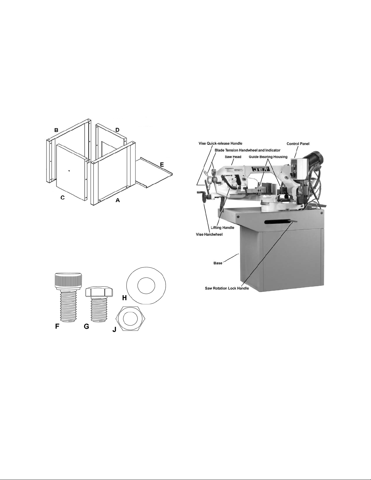
Shipping Contents
Contents of the Carton
1 Band Saw (not shown)
1 Front Stand Panel (A)
1 Rear Stand Panel (B)
1 Left Stand Panel (C)
1 Right Stand Panel (D)
1 Bottom Plate (E)
1 Operating Instructions/Parts List
1 Warranty Card
Saw Head
The saw head (Figure 1) consists of a drive
motor, gearbox, bl ade wheels, blade gu ides and
supports, control panel, blade tension
mechanism, wire brush, and the saw blade.
The drive wheel is instal led on the output shaft
of the gearbox. The driven wheel is located o n
the left side of the machine and is m ounted on a
shaft that is part of the blade tension mechanism. The blade tension mechanism is used to
tighten the saw blade on the blade wheels.
Blade tension generall y req uir es adj us tment only
after the saw blade is changed , but the tension
should be monitored with the convenient blade
tension indicator.
Contents of the Carton
Hardware
04 M8 x 25 Socket Head Cap Screw (C)
12 M8 x 20 Hex Cap Screw (D)
28 M8 Flat Washer (E)
24 M8 Hex Nut (F)
Hardware (Actual Size)
Machine Features
Figures 1 depicts t he m ain f eatures of the Mod el
J-9225 Bandsaw. The machine consists of a
machine base onto which is installed a saw
head.
Machine Base
The machine base consists of four panels that
require assembly.
Figure 1
Work Stop
A work stop is provided with the machine to
allow cutting multiple pieces of identical length
(refer to Figure 6). The stop consists of a s et rod
onto which is installed a distance set bracket,
stop rod assembly and two lock handles. The
rod is installed in a b ore in the front of the saw
bed. The distance set br ack et is moved in or out
on the set rod to establish the length of the
workpiece and the stop rod can be adjusted to
accommodate workpieces of various widths.
Control Panel
The control panel is mounted on the top of the
saw head. Refer to the Controls and Indicators
section (page 9) for a des cripti on of the con trols.
Switches and fuses required for operation and
protection of the drive motor are inside the box.
7
Page 8
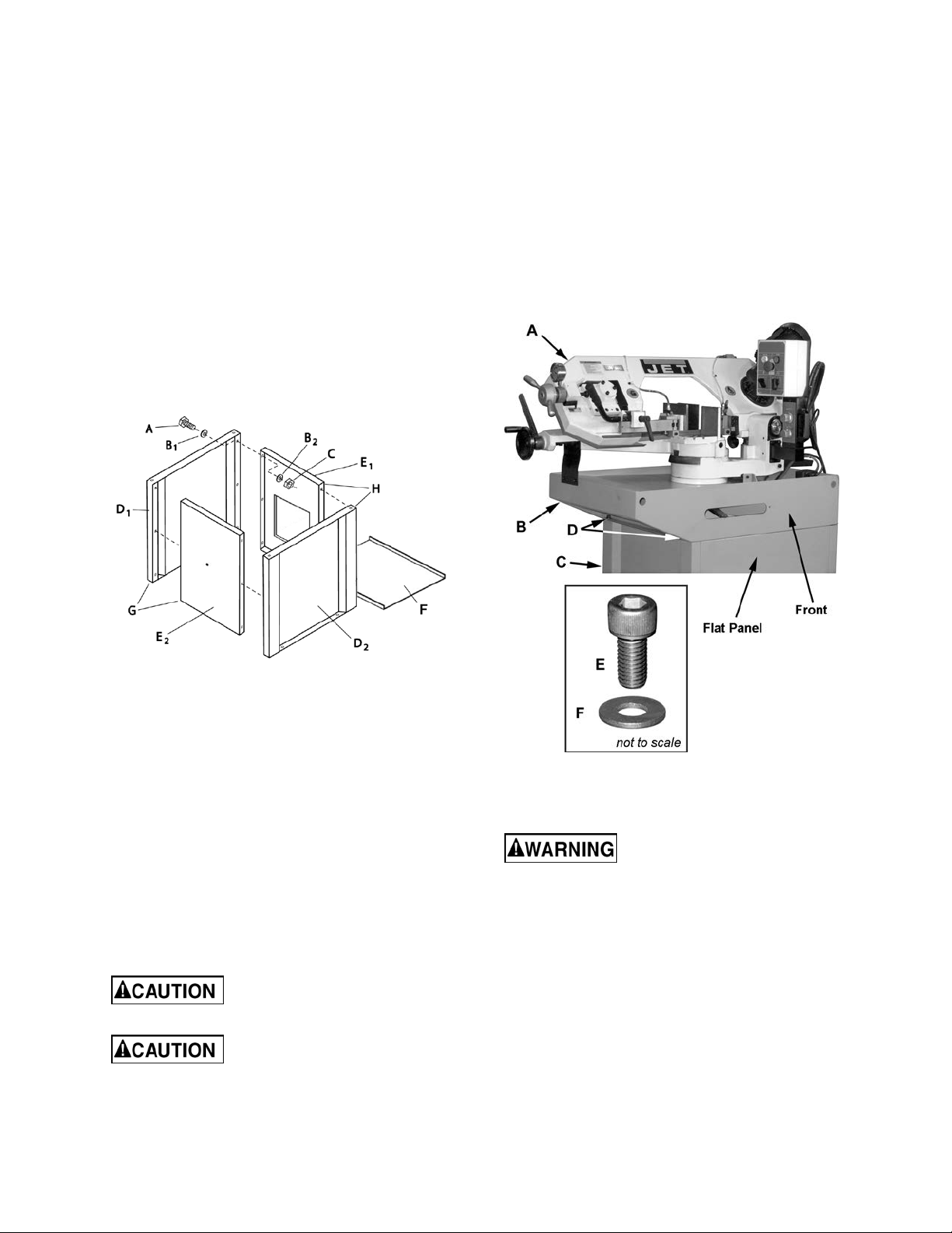
Assembly
Stand Assembly
Tools required for assembly:
Two 1/2-inch wrench es (Note: A ratch et wrench
may speed assembly time.)
Referring to Figure 2:
1. Assemble the rear (D
panels with three M8 x 20 hex cap screws
(A), six M8 flat washers (B
M8 hex nuts (C). Tighten the hex nuts.
2. Assemble E
3. Position bottom plate (F) in stand.
and D2 in the same manner.
2
) and right side (E1)
1
, B2) and three
1
Referring to Figure 3:
1. The saw (A) and stand top (B) come as an
assembled unit. Us e a hoist to l ift and place
the saw onto the stand (C).
Note that the front of the saw faces the
same direction as the flat panel of the stand.
2. Adjust the stand top (B) and stand (C) so the
corner mounting holes (D) are aligned.
3. Secure the stand top (B) to the stand (C)
with four each M8 hex socket head screws
(E) with M8 flat washers (F). Tighten with an
8mm hex wrench.
4. Finish assembling E
the same manner as above.
to D1 and E1 to D2 in
2
Figure 2
Mounting Saw to Stand
Tools required for assembly:
– 8mm hex wrench
Remove any plastic or holding straps from
around the bandsaw. Are as of the machine have
been given a protective coating at the factory.
This should be removed using a soft cloth
moistened with kerosene or a cleanerdegreaser. Do not use gasoli ne, paint thin ner, or
lacquer thinner as these will damage painted
surfaces. Do not use an abrasive pad.
Determine the final location for the saw and
allow for a sufficient work space around it.
The saw is extremely heavy.
Use a hoist to lift.
When moving the saw/stand
top assembly the cutting head, or “bow”,
should be in the down position.
Figure 3
Electrical Connection
All electrical connections
must be done by a qualified
electrician. All adjustments or repairs must
be done with the machine disconnected from
the power source, unplugged. Failure to
comply may result in serious injury!
The Model J-9225 bandsaw is rated at 230V.
This machine is not sup plied with a plug. Use a
plug and outlet rated at least 20amps. The
circuit for the mac hine should also be protected
by at least a 20 amp circuit breaker or fuse.
Make sure that the blade moves in the
correct direction. If it does not, simply reverse
two of the phase wires on the supply input.
The sawing machine is now ready for use.
8
Page 9
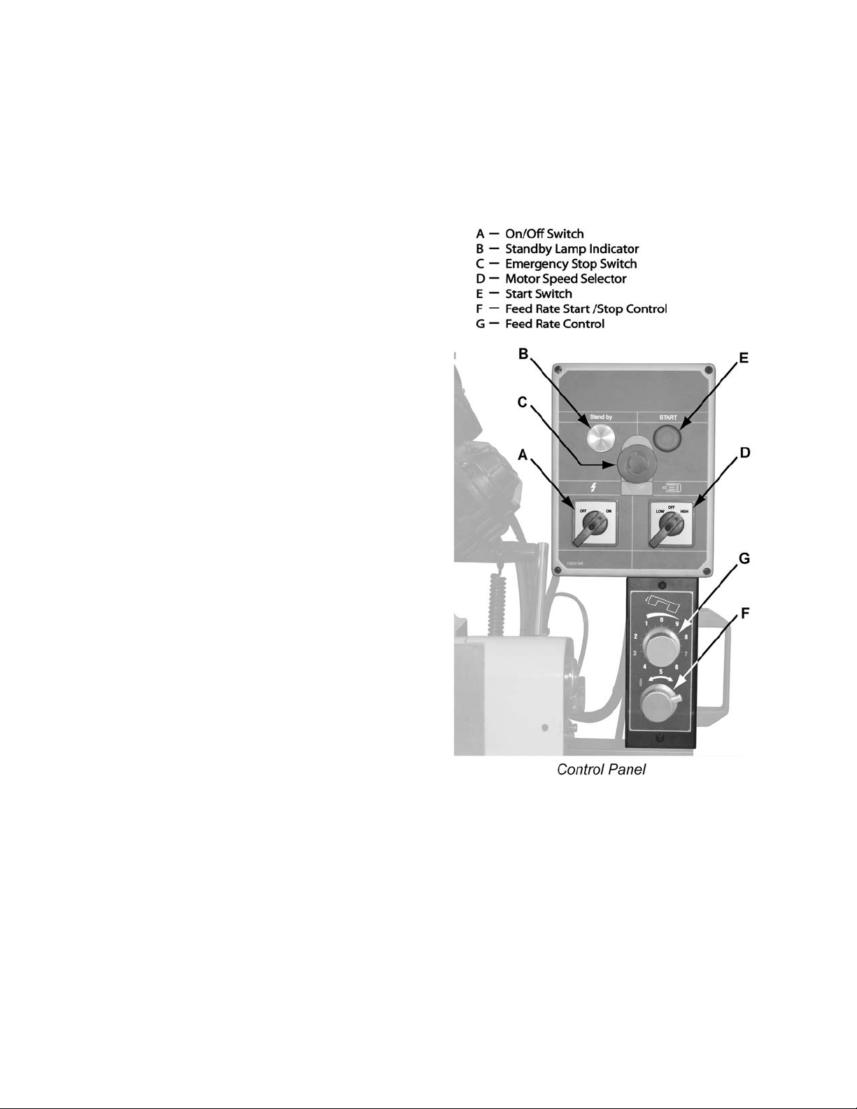
Controls and Indicators
Control Panel
The operating controls for the bandsaw are
located on the control panel (Figure 4) and
consist of the following controls and indicators:
Emergency Stop Switch – by depressing this
switch the user can quickly stop the machine
when it is in operat ion; to restart, turn clockwise
slightly to release then press Start switch
Feed Rate Control – used in conjunction with the
Feed Rate Start/Stop Control (see below); this
knob is used to set the downward head speed
that is applied to the s aw blad e. The f eed rate is
proportional to the opening of the valve. When
set to zero, the sa w head is locked in position.
Increasing the valve open ing (counter-clockwise
adjustment) increas es the feed rate; decreasing
the valve opening (clockwise adjustment)
reduces the feed rate.
Feed Rate Start/Stop Control – used in
conjunction with the Feed Rate Control (see
above); in the locked position the saw head is
prevented from descending; in the unlocked
position the saw head will descend at the rate
determined by the Feed Rate Control setting.
Motor Speed Selector – select Low for 137
SFPM, High for 275 SFPM; machine will not
operate when Off is selected.
On/Off Switch – main power switch
Standby Lamp Indicator – indicates that po wer is
present, i.e., machine is plugged in and On/Off
Switch in set to ON.
Start Switch – pres s to start machine, also: set
On/Off Switch to ON, select Motor Speed
Selector to Low or High, Emergency Stop must
be released.
Blade Speeds
The Model J-9225 bandsaw has two blade
speeds which are set by the Motor Speed
Selector dial (D, Fig . 4). In normal operation t he
machine is stopped, the speed selected
(Low/High) then restarted. Changing the speed
while in operation will shu t the machine off and
will require restarting (E, Fig. 4).
Figure 4
9
Page 10

Blade Selection
Operations
The bandsaw is deliver ed with a saw blade that
is adequate for a variety of cut-off jobs on a
variety of comm on materials. A gen eral-purpose
blade is provided as standard equipment with
the machine. After-market blades can be
acquired for specific cutting jobs.
A coarse blade could be used for a solid steel
bar, but a finer tooth blade would be used on a
thin-wall steel tube. In g eneral, the blade choic e
is determined by the thickness of the material;
the thinner the materials; the finer the tooth
pitch.
A minimum of three teeth should be on the
workpiece at all times for proper cutting. The
blade and workpiece can be damaged if the
teeth are so far apart that they straddle the
workpiece.
For very high production on cutting of special
materials, or to cut hard-to-cut materials suc h as
stainless steel, tool steel, or titanium, call JET
for more specific blade recommendations. JET
can provide you with very specific instructions
regarding the best blade ( and coolant or cutting
fluid, if needed) for the material or shape
supplied.
Hydraulic Feed Control
The weight of the saw head provides the force
needed to cut through the workpiece. T he cut -off
saw has a hydraulic cylinder that controls the
feed rate of the saw.
The hydraulic feed control circuit consists of a
single acting hydraulic cylinder and a feed rate
control. The feed contr ol cylinder resists motion
in the downward direction to control the feed
rate. The control cylinder offers no resistance
when raised upward.
The feed rate control knob (Figure 4) controls
the rate at which the s aw head is lowered. The
control knob (needle valve) controls the rate at
which the hydraulic fluid is released from the
hydraulic cylinder. When the needle valve is
closed, the cylinder is locked. With the needle
valve slightly open, the c ylinder permits s low, or
light, downward forc e. Opening the needle v alve
further increases the feed rate.
The needle valve is adjusted until the saw is
operating efficientl y. The efficiency of operation
is usually evaluate d b y obs er ving c h ip f ormation.
Blade efficiency is further described below.
Blade Break-in Procedures
New blades are very sharp and, therefore, have
a tooth geometry that is easily damaged if a
careful break-in procedure is not followed.
Consult the blade manufacturer’s literature for
break-in of specif ic blades on specific m aterials.
However, the following procedure will be
adequate for break-in of JET-supplied blades on
lower alloy ferrous materials.
1. Clamp a section of round s tock in the vise.
The stock should be 2 inches or larger in
diameter.
2. Operate the saw at low speed. S tart the cut
with a very light feed rate.
3. When the saw has com pleted 1/3 of the cut,
increase the feed rate slightl y and allow the
saw to complete the cut.
4. Keep the hydraulic cylinder needle valve in
the same position and begin a second cut
on the same or similar workpiece.
5. When the blade has completed ab out 1/3 of
the cut, increase the feed rate.
Watch the chip formation until cutting is at its
most efficient rate and allow the saw to
complete the cut (refer to Evaluating Blade
Efficiency below). The blade is no w consid-
ered ready for use.
Evaluating Cutting Efficiency
Is the blade cutting ef ficiently? The best way to
determine this is to obs erve the chips f ormed by
the cutting blade.
If the chip formation is powder y, then the feed is
much too light or the blade is dull.
If the chips formed are curled, but c ol ored – blue
or straw colored from heat generated during the
cut – then the feed rate is too high.
If the chips are slightly curled and are not
colored by heat – the b lade is sufficiently sharp
and is cutting at its most efficient rate.
10
Page 11

Setting the Work Stop
Referring to Figure 5:
The work stop is an accessory that is included
with the JET J-9225 Bandsaw. It is used to set
up the saw for making multiple c uts of the same
length.
Do not allow the blade to rest
on the workpiece when the saw is not
cutting.
Installation
1. Insert the distance set rod (A) into the hole
(B) at the front of the base as shown.
2. Secure by tightening the socket setscrew
(C) with a 3mm hex wrench.
Adjustment
3. The distanc e set brac ket (D) is m oved a long
the distance set rod (A) by loosening the
lock handle (E). The stop rod (F) can be
repositioned (G) by loosening lock handle
(H) and also by rotating the set rod (A) to
reposition the angle of the bracket (D).
Quick Release Vise Operation
Referring to Figure 6:
The vise on the J-9225 bandsaw comes
equipped with a quick-release handle that
permits the workpiec e to be rapidly repositioned
or changed for a repeated cutting operation
while requiring onl y one initial adjustment of the
vise handwheel. This is done as follows:
Figure 5
1. Place the quick-release handl e (A) in the up
position as shown.
2. Turn the handwheel (B) counterclockwise
until the workpiece can be placed in
position.
3. Place the workpiece (C) in the vise (D) and
against the work stop (E); turn the hand-
wheel (B) unti l the vise beg ins to clam p onto
the workpiece. Then back the handwhe el off
just enough to perm it the workpiece to slide
in and out of the vise.
4. Place the quick-release handle (A) in the
down position. The work piece is secure and
ready for cutting.
The vise is now set up for a repeated cutting
operation. Simply raise the quick-release
handle, reposition or replace the workpiece a nd
reset the handle down again.
11
Figure 6
Page 12

Miter Cuts
saw is
olant pump must be
submerged before operating to prevent damage
A coolant pump, which provides coolant to the
flow from the nozzles. Coolant flow should be
stop coolant flow, turn the control valves fully
) and
Referring to Figure 7, the J-9225 band
capable of making angle cuts from 0–60º. The vise
remains stationar y while the s aw head is adjusted as
follows:
1. Place the saw head (F) in the ra ised position so
the blade doesn't catch in the table slots.
2. Set the lock handle (A) to the unlock position as
indicated by the arrows.
3. Using handles (B and C), rotate the saw he ad (F)
to any desired angle within a range of 0º (square
cut) to 60º, setting it to the scale (D) on the base.
4. Set the lock handle (A) to the lock position.
Note: Two miter stops (E) on either side of the saw
base set the miter range of 0–60º. Adjust only if
necessary so the saw travel stops at 0º and 60º.
Coolant Flow Control
The co
to the pump.
workpiece, runs at all times when the machine is
turned on.
Two coolant flow control valves (A, Fig . 8), loca t ed on
the top of the bearing blocks, control the amount of
Figure 7
adjusted to be no more than the saw bla de can draw
into the workpiece by the m ovement of the blade. T o
counterclockwise.
Adjustments
Blade Guide Adjustment
Refer to Figure 9. The J-9225 Bandsaw has two
blade guide assemblies; one is stationary (A
mounted to the body of the saw head. The other,
consisting of a blade guide support or bracket (B) and
blade guide (C), is adjustable.
The position of the blade guides is important in order
to make accurate cuts and prolong blade life and is
determined by the size of the workpiece. Adjustm ent
is made as follows:
1. Place the workpiece (D) in the vise (E) and clam p
tightly.
2. Loosen the lock handle (F).
3. Slide the guide support (B) left or right so that it
just clears the piece to be cut (D).
4. Tighten the lock handle (F).
Figure 8
Figure 9
12
Page 13

Bearing and Guide Block Adjustment
from the blade can be adjusted for optimal
spacing. For most efficient
head screwdriver. Set the
s the blade without
Outer
Roller
Inner
Roller
Locking Screw
INCORRECT CORRECT
Saw Blade
Saw Blade
Referring to Figure 10:
Guide bearings and carbide guide blocks are located
on either side of the saw blade and provide stability
for the blade when the saw is in operation. These
bearings rotate on an ec centric shaft so th e distance
performance.
Guide blocks provide additional blade stability.
Guide bearings and guide block s are initially adjusted
at the factory and should rarely require adjustment.
It is always better to try a new blade when cutting
performance is poor. If performance remains poor
after changing the blade, check the blad e guides for
proper guide bearing
operation and maximum accuracy, clearance
between the blade and the guide b earings should be
0.001-inch. The bear ings will still turn f reely with this
clearance. If the clear anc e i s inc orr ec t, the bla de may
track off the drive wheel.
Disconnect the bandsaw saw
from its electrical power source.
If required, adjust the bearing and guide block on one
assembly then the other as follows:
1. Using a 3mm hex wrench, loosen two set-screws
(A) that secure the eccentric bushings.
2. Using a 4mm hex wrench, loosen the socket
head cap screw (E) securing the guide block (F).
3. With a 12mm wrench, loos en the hex nut (G) that
secures the guide block adjustment setscrew (H).
4. Position the bearings (B) by tur ning the bushings
(C) with a flatclearance between the bearings (B) and blade
(D) at approximately 0.001 inch.
When properly adjus ted, the b lade s houl d be in a
vertical position be tween the bearings as shown
in Figure 11.
5. Secure the bushing settings by tightening the
setscrews (A).
6. With a 4mm wrench adjust setscrew (H) so the
guide block (F) support
pinching the blade.
7. Tighten the socket head cap screw (E).
Figure 10
8. Maintain the position of the setscrew ( H) with the
hex wrench while tightening the hex nut (G).
13
Figure 11
Page 14

Blade Tension
when a cut is completed. If not, the limit switch
off saw from
See Adjusting the proper Bl ade Tension on page 16.
Limit Switch Adjustment
Refer to Figure 12.
The J-9225 bandsaw should shut off automatically
probably needs to be adjusted as follows:
Disconnect the cut-
its electrical power source.
1. Place the saw in the lo wered position to represent the completion of a cutting operation
2. Using a crosspoint s cr ewdr i ver an d 5/16 " wrench,
loosen two mounting screws (A).
3. Position the limit switc h assembly (B) to actuate
to the off position as it pres ses against the back
plate (C) of the control panel when the saw has
cut through the workpiece.
Figure 12
14
Page 15

Maintenance
Figure 13
Changing Blades
Refer to Figure 13 except where specified
otherwise.
Use leather gloves when
changing the saw blade to protect your
hands from cuts and scratches. Use
protective eye wear that meets ANSI
Specification Z87.1
Disconnect the cut-off saw
from its electrical power source.
Tools required:
-- 3mm, 4mm and 5mm hex wrenches
-- 12mm wrench
Removing the Blade
1. Lock the hydraulic cyli nder that controls the
descent of the saw head with the fee d rate
start/stop control (F, Fig. 4). Raise the saw
head (A) about half way up.
2. Remove the wheel cover (B) and blade
guards (C, D) and brush (M).
3. Turn the blade tension handle (J) counter-
clockwise until the blade (E) hangs loose.
4. Pull the blade (E) off the drive w heel (F) and
idler wheel (G) and out of the b lade guides
, H2). Store the removed blade carefully
(H
1
before proceeding.
Installing New Blade
5. Slide the new blade into the blade guides
, H2), then loop the bla de (E) around the
(H
1
drive wheel (F) and idler w heel (G) such that
the teeth face towards the rear of the saw
and the smooth side faces towards the front.
6. Push the blade so it seats against the
shoulders of the wheels (F, G).
Adjusting the proper Blade Tension
7. When it is seated against t he shoulder, turn
the blade tension handle (J) clockwise to
increase the tension until the scale for the
1" blade tension measures 20–28KPSI (K)
(green zone) on the tension indicator (L).
8. Replace the wheel cover (B) and blade
guards (C, D) and brush (M).
9. Reconnect the saw to the electrical power
source.
15
Page 16

Cleaning
Coolant
Clean off any preservative on machine surfaces.
After cleaning:
1. Coat machined surfaces of the cutoff saw
with a medium consistency machine oil.
Reapply the oil coating at least every six
months.
2. Clean up accumulated saw cuttings after
use. Make sure th e lea d sc r ew an d r a pi d n ut
are kept free from saw cuttings and other
material that would cause damage.
3. Clean the chip sludge from the c oolant tank.
The frequency should be d eter mined by how
often the saw is used.
Lubrication
Lubricate the following components at the
specified frequencies and using the lubricants
defined as follows:
Ball Bearings – the bearings are lubr icated and
sealed – periodic lubrication is not required.
Blade Guide Bearing – the bear ings are lubricated and sealed – periodic lubrication is not
required.
Change coolant on a frequency appropriate to
the type of coolant being used. Oil based
coolants can sour. Refer to the coolant
supplier’s instructions for change frequency.
The general-purpose coolant is a mixture of
water-soluble oil or synthetic based cool ant and
water. Mix one part of coolant to ten parts of
water (one quart of oil to ten quarts water).
Twelve quarts of coolant is the amount required
for the coolant pum p to operate properl y. Verify
that the coolant level is visible in the indicator
(Figure 14).
There are numerous coola nts on the m arket that
are formulated for special applications. Consult
your local distribut or for details in the event you
have a long range production task, or are
required to cut some of the more exotic
materials.
Wheel Bushings – six to e ight drops of oil each
week.
Pivot Points, Shafts, and Bearing areas – six
to eight drops of oil each week.
Figure 14
16
Page 17

Troubleshooting
1. Material loose in vise.
1. Clamp work securely.
Check Machinist’s Handbook for
speed/feed appropriate for the
Check Machinist’s Handbook for
Adjust blade tension to the point
Start the motor before placing the
1. Blade teeth too coarse.
Hard spots in workpiece or scale
Operating saw without pressure on
1. Use a finer tooth blade.
Increase feed pressure by reducing
Do not run blade at idle in/on
1. Workpiece not square with blade.
1. Adjust vise so it is square with the
Fault Probable Cause Suggested remedy
Excessive blade
breakage
Premature blade
dulling
2. Incorrect speed or feed.
3. Teeth too coarse for material.
4. Incorrect blade tension.
5. Saw blade is in contact with workpiece before the saw is started.
6. Misaligned guides.
7. Cracking at weld.
2. Blade speed too high.
3. Inadequate feed pressure.
4.
on/in workpiece.
5. Work hardening of material
(especially stainless steel).
6. Insufficient blade tension.
7.
workpiece.
2.
material being cut.
3.
recommended blade type.
4.
where the blade just does not slip o n
the wheel.
5.
saw on the workpiece.
6. Adjust guides.
7. Longer annealing cycle.
2. Try a lower blade speed.
3. Decrease spring tension.
4. Increase feed press ure (hard spots).
Reduce speed, increase feed pressure (Scale).
5.
spring tension.
6. Increase tension to proper level.
7.
material.
2. Feed pressure too fast.
3. Guide bearings not adjusted
4. Inadequate blade tension.
Bad cuts (crooked)
5. Span between the two blade guides
6. Dull blade.
7. Incorrect blade speed.
8. Blade guide assembly is loose.
9. Blade guide bearing assembly loose.
10. Blade track too far away from wheel
11. Guide bearing worn.
properly.
too wide.
flanges.
17
blade. (Always clam p the workpiece
tightly in the vise.)
2. Decrease pressure.
3. Adjust guide bearing clearance to
0.001 inch (0.002 inch maximum).
4. Gradually increase blade tension.
5. Move blade guide bracket closer to
work.
6. Replace blade.
7. Check blade speed.
8. Tighten blade guide assembly.
9. Tighten blade guide bearing
assembly.
10. Adjust blade tracking.
11. Replace worn bearing.
Page 18

Troubleshooting (cont.)
1. Blade speed too high for feed
1. Reduce blade speed and feed
1. Blade is binding in the cut.
1. Decrease feed pressure.
1. Blade guides worn
Blade guide bearing bracket is
1. Replace blade guides.
Fault Probable Cause Suggested remedy
Bad cuts (rough)
Blade is twisting
Unusual wear on
side/back of blade
pressure.
2. Blade is too coarse.
2. Blade tension too high
2. Blade guide bearings not adjus ted.
3.
loose.
pressure.
2. Replace with finer blade.
2. Decrease tension on Blade
2. Adjust blade guide bearings.
3. Tighten blade guide bearing bracket.
Parts
Replacement Parts
Replacement parts are liste d on the follo wing pages . To order parts or reach our service de partment, c all
800-274-6848 Monda y through Friday (see our website for bus iness hours, www.jettools.com). Having
the Model Number and Ser ial Num ber of your mac hine avail able whe n you call will al low us t o serve you
quickly and accurately.
18
Page 19

Saw Assembly – Parts
Index No. Part No. Description Size Qty
1 ............... J-9225-01 ................. Body Frame.......................................................... .................................... 1
2 ............... J-9225-02 ................. Anchor Bloc k ........................................................ .................................... 1
2A ............. J-9225-02A .............. Anchor Plate......................................................... .................................... 1
2B ............. TS-2245102 ............. Button Head Socket Screw .................................. M5x10 ......................... 2
3 ............... 9225-03 .................... Shaft ..................................................................... .................................... 1
4 ............... TS-1504061 ............. Socket Head Cap Screw ...................................... M8x30 ......................... 3
5 ............... 9225-05 .................... Bearing Co ver ...................................................... .................................... 2
6 ............... 9225-06 .................... Tapered Bearing .................................................. .................................... 2
7 ............... TS-1551061 ............. Lock Washer ........................................................ M8 ............................... 3
10-1 .......... 9180-10-1 ................. Blade Tension Gauge .......................................... .................................... 1
11 ............. 9180-11 .................... Bearing ................................................................. .................................... 1
12 ............. 9180-12 .................... Handle .................................................................. .................................... 2
13 ............. 9180-13 .................... Hub ....................................................................... .................................... 1
14 ............. 9180-14 .................... Spring Washer ..................................................... øID16.3xø31.5x1.8t .. 14
15 ............. 9225-15 .................... Lead Screw .......................................................... .................................... 1
16 ............. TS-154010 ............... Hex Nut ................................................................ M16 ............................. 1
17 ............. TS-1504041 ............. Socket Head Cap Screw ...................................... M8x20 ......................... 3
18 ............. J-9225-18 ................. Fixed Block........................................................... .................................... 1
19 ............. 9180-19 .................... Pin ........................................................................ ø 5x40 ......................... 2
20 ............. 9225-20 .................... Locking Handle .................................................... M10x60 ....................... 1
21 ............. J-9225-21 ................. Fixed Block........................................................... .................................... 1
22 ............. TS-1504041 ............. Socket Head Cap Screw ...................................... M8x20 ......................... 2
23 ............. TS-1523051 ............. Set Screw ............................................................. M6x16 ......................... 4
25 ............. 9225-25 .................... Blade Adjus t Bar .................................................. .................................... 1
26 ............. TS-1524021 ............. Set Screw ............................................................. M8x10 ......................... 2
27 ............. TS-1503021 ............. Socket Head Cap Screw ...................................... M6x10 ......................... 1
28 ............. 9225-28 .................... Lift Handle ............................................................ .................................... 1
29 ............. 9180-29 .................... Handle Grip .......................................................... .................................... 1
32 ............. TS-2246302 ............. Button Head Socket Screw .................................. M6x30 ......................... 4
35 ............. TS-1503011 ............. Socket Head Cap Screw ...................................... M6x8 ........................... 2
38 ............. 9225-38 .................... Guide Block (Front) .............................................. .................................... 1
39 ............. TS-1524051 ............. Set Screw ............................................................. M8x20 ......................... 2
40 ............. TS-1540061 ............. Hex Nut ................................................................ M8 ............................... 2
41 ............. 9225-41 .................... Guide .................................................................... .................................... 2
42 ............. 9225-42 .................... Guide .................................................................... .................................... 2
43 ............. 9225-43 .................... Eccentric Guide .................................................... .................................... 2
44 ............. BB-608ZZ ................. Bearing ................................................................. 608ZZ.......................... 4
45 ............. 9180-45 .................... C-Retainer Ring ................................................... ø8 ................................ 4
46 ............. 9225-46 .................... Eccentric Guide .................................................... .................................... 2
47 ............. TS-2246162 ............. Button Head Socket Screw .................................. M6x16 ......................... 2
48 ............. J-9225-48 ................. Blade Guard ......................................................... .................................... 1
52 ............. TS-1523011 ............. Set Screw ............................................................. M6x6 ........................... 2
54 ............. 9225-54 .................... Guide Block (Rear) .............................................. .................................... 1
55 ............. TS-1523011 ............. Set Screw ............................................................. M6x6 ........................... 2
56 ............. 9180-56 .................... Button Head Socket Screw .................................. M8x35 ......................... 2
58 ............. J-9225-58 ................. Blade Cover ......................................................... .................................... 1
59 ............. TS-1550031 ............. Flat Washer .......................................................... M5 ............................... 2
60 ............. TS-2245102 ............. Button Head Socket Screw .................................. M5x10 ......................... 2
63 ............. TS-1505061 ............. Socket Head Cap Screw ...................................... M10x40 ....................... 2
64 ............. TS-1505031 ............. Socket Head Cap Screw ...................................... M10x25 ....................... 2
65 ............. 9225-65 .................... Frame Pivot Shaft ................................................ .................................... 1
66 ............. 9225-66 .................... Cover .................................................................... .................................... 2
67 ............. 9225-67 .................... Tapered Bearing .................................................. .................................... 1
71 ............. 9225-71 .................... Motor .................................................................... 1.5HP, 3Ph, 230V ....... 1
71-1 .......... 9225-71-1 ................. Key ....................................................................... 6x6x40 ........................ 4
72 ............. TS-1482051 ............. Hex Cap Screw .................................................... M6x25 ......................... 4
19
Page 20

Saw Assembly – Parts
Index No. Part No. Description Size Qty
73 ............. TS-2361061 ............. Lock Washer ........................................................ M6 ............................... 4
74GA ........ 9225-74GA ............... Gear Box Assembly ............................................. .................................... 1
75 ............. TS-1551071 ............. Lock Washer ........................................................ M10 ............................. 4
76 ............. TS-1505021 ............. Socket Head Cap Screw ...................................... M10x20 ....................... 4
77 ............. 9225-77 .................... Reducer Cover ..................................................... .................................... 1
78 ............. 9180-78 .................... Hose Fitting .......................................................... ø8x1/4"PT ................... 1
79 ............. TS-1503041 ............. Socket Head Cap Screw ...................................... M6x16 ......................... 2
80 ............. 9180-80 .................... Coolant B lock ....................................................... .................................... 1
81 ............. 9180-81 .................... Hose ..................................................................... ø6x240L ...................... 1
82 ............. 9180-82 .................... Valve .................................................................... 1/8" .............................. 2
83 ............. 9180-83 .................... Hose Fitting .......................................................... ø6x1/8"PT ................... 4
84 ............. 9225-84 .................... Hose ..................................................................... ø6x970L ...................... 1
85 ............. TS-1505041 ............. Socket Head Cap Screw ...................................... M10x30 ....................... 1
86 ............. 9225-86 .................... Washer ................................................................. .................................... 1
87 ............. 9180-87 .................... Round Head Key .................................................. 8x7x50 ........................ 1
88 ............. 9225-88 .................... Output Shaft ......................................................... .................................... 1
89 ............. 9225-89 .................... Round Head Key .................................................. 8x7x25 ........................ 1
90 ............. 9225-90 .................... Bearing ................................................................. .................................... 1
91 ............. 9225-91 .................... Spring Sup port ..................................................... .................................... 1
92 ............. 9225-92 .................... Spring ................................................................... .................................... 1
93 ............. TS-1550071 ............. Flat Washer .......................................................... M10 ............................. 2
93-1 .......... 9225-93-1 ................. Limit Switch Bracket ............................................. .................................... 1
93-2 .......... TS-1502041 ............. Socket Head Cap Screw ...................................... M5x16 ......................... 1
93-3 .......... TS-1551031 ............. Lock Washer ........................................................ M5 ............................... 1
93-4 .......... TS-1550071 ............. Flat Washer .......................................................... M10 ............................. 1
93-5 .......... TS-1540071 ............. Hex Nut ................................................................ M10 ............................. 1
94 ............. TS-1505061 ............. Socket Head Cap Screw ...................................... M10x40 ....................... 1
95 ............. 9225-95 .................... Cylinder Assembly ............................................... .................................... 1
96 ............. 9225-96 .................... Idler Wheel ........................................................... .................................... 1
97 ............. TS-1551071 ............. Lock Washer ........................................................ M10 ............................. 2
98 ............. TS-1505041 ............. Socket Head Cap Screw ...................................... M10x30 ....................... 2
99 ............. 9225-99 .................... Nut ........................................................................ .................................... 1
100 ........... ................................. Blade (local purchase) ......................................... 1”x.035x96.5”x5/8VT .. 1
101 ........... 9225-101 .................. Drive Wheel.......................................................... .................................... 1
102 ........... 9225-102 .................. Drive Shaft Washer .............................................. .................................... 1
103 ........... TS-1492021 ............. Hex Cap Screw .................................................... M12x30 ....................... 1
104 ........... 9225-104 .................. Frame Back Cover ............................................... .................................... 1
105 ........... TS-1503041 ............. Socket Head Cap Screw ...................................... M6x16 ......................... 4
106 ........... TS-1550041 ............. Flat Washer .......................................................... M6 ............................... 4
106-1 ........ 9225-106-1 ............... Washer ................................................................. .................................... 1
107 ........... TS-2245202 ............. Button Head Socket Screw .................................. M5x20 ......................... 3
108 ........... 9225-108 .................. Hose Clip .............................................................. .................................... 3
109 ........... TS-2248162 ............. Button Head Socket Screw .................................. M8x16 ......................... 2
115 ........... 9225-115 .................. Label .................................................................... .................................... 1
116 ........... 9225-116 .................. Cover .................................................................... .................................... 1
117 ........... TS-2245162 ............. Button Head Socket Screw .................................. M5x16 ......................... 2
165A ......... 9225-165S ............... Stock Stop Assembly (#165-1 thru #165-8) ......... .................................... 1
165-1 ........ 9180-165-1 ............... Stop Block ............................................................ .................................... 1
165-2 ........ TS-1550061 ............. Flat Washer .......................................................... M8 ............................... 2
165-3 ........ 9180-165-3 ............... Locking Handle .................................................... .................................... 2
165-4 ........ 9180-165-4 ............... Stock Stop Rod .................................................... .................................... 1
165-5 ........ 9225-165-5 ............... Distance Set Rod ................................................. .................................... 1
165-7 ........ 9225-165-7 ............... Scale .................................................................... .................................... 1
165-8 ........ 9225-165-8 ............... Rivet ..................................................................... ø2 ................................ 4
170 ........... 9225-170 .................. Hand Wheel ......................................................... .................................... 1
171 ........... 9180-171 .................. Pin ........................................................................ ø5x35 .......................... 1
20
Page 21

Saw Assembly – Parts
Index No. Part No. Description Size Qty
172 ........... 9180-172 .................. Bearing Co ver ...................................................... .................................... 1
173 ........... 9180-173 .................. Bearing ................................................................. ø30xø47x3.5 ............... 1
174 ........... 9180-174 .................. Vise Handle .......................................................... .................................... 1
175 ........... 9180-175 .................. Spring ................................................................... .................................... 1
176 ........... 9180-176 .................. Bushing ................................................................ .................................... 1
178 ........... 9225-178 .................. Washer ................................................................. ø6.5xø18x1.5 .............. 1
179 ........... TS-1503041 ............. Socket Head Cap Screw ...................................... M6x16 ......................... 1
180 ........... J-9225-180 ............... Front Moveable Vise Jaw ..................................... .................................... 1
181 ........... 9225-181 .................. Vise Jaw Insert ..................................................... .................................... 1
182 ........... TS-1514011 ............. Flat Head Socket Screw ...................................... M6x12 ......................... 2
183 ........... TS-1505041 ............. Socket Head Cap Screw ...................................... M10x30 ....................... 2
184 ........... TS-1551071 ............. Lock Washer ........................................................ M10 ............................. 2
185 ........... 9225-185 .................. Vise Jaw ............................................................... .................................... 1
186 ........... J-9225-186 ............... Rear Stationary Vise Jaw ..................................... .................................... 1
187 ........... TS-1524021 ............. Set Screw ............................................................. M8x10 ......................... 1
188 ........... 9225-188 .................. Grooved Jaw Insert .............................................. .................................... 1
189 ........... TS-1514021 ............. Flat Head Socket Screw ...................................... M6x16 ......................... 2
190 ........... 9225-190 .................. Lead Screw .......................................................... .................................... 1
191 ........... TS-1524051 ............. Set Screw ............................................................. M8x20 ......................... 1
193 ........... 9225-193 .................. Socket Head Cap Screw ...................................... M6x110 ....................... 2
194 ........... J-9225-194 ............... Swivel Arm ........................................................... .................................... 1
195 ........... TS-1540071 ............. Hex Nut ................................................................ M10 ............................. 2
196 ........... 9225-196 .................. Vise Swivel Rod ................................................... .................................... 1
197 ........... 9180-197 .................. O-Retainer Ring ................................................... ø19.8xø2.4 .................. 1
198 ........... TS-2210451 ............. Hex Cap Screw .................................................... M10x45 ....................... 2
199 ........... 9225-199 .................. Bearing ................................................................. .................................... 1
200 ........... 9225-200 .................. Bushing ................................................................ .................................... 1
201 ........... 9225-201 .................. Nut ........................................................................ .................................... 1
202 ........... 9180-202 .................. Spring Eye Bolt .................................................... .................................... 1
202-1 ........ TS-1540071 ............. Hex Nut ................................................................ M10 ............................. 1
207 ........... TS-1523051 ............. Set Screw ............................................................. M6x16 ......................... 2
209 ........... 9225-209 .................. Control Box Base ................................................. .................................... 1
209-1 ........ 9225-209-1 ............... Speed Valve Knob ............................................... .................................... 1
209-2 ........ 9225-209-2 ............... Throttle Valve Knob ............................................. .................................... 1
210-1 ........ 9225-210-1 ............... Retaining O-Ring ................................................. .................................... 1
214 ........... 9225-214 .................. Control Box Label ................................................ .................................... 1
215 ........... ................................. Electrical Control Box Assembly (Reference Only) .................................. 1
216 ........... 9180-216 .................. Hex Socket Plug .................................................. 3/8"PT ......................... 1
216-1 ........ 9180-216-1 ............... Washer ................................................................. .................................... 1
217 ........... 9225-217 .................. Sight Glass ........................................................... .................................... 1
218 ........... 9225-218 .................. O-Retainer Ring ................................................... ID195x5.7W ................ 1
219 ........... TS-1551071 ............. Lock Washer ........................................................ M10 ............................. 6
220 ........... TS-1505021 ............. Socket Head Cap Screw ...................................... M10x20 ....................... 6
221 ........... J-9225-221 ............... Stand Top............................................................. .................................... 1
221-1 ........ J-9225-221-1 ............ Swivel Arm Base .................................................. .................................... 1
222 ........... 9180-222 .................. Screen .................................................................. .................................... 1
223 ........... TS-2284082 ............. Pan Head Screw .................................................. M4x8 ........................... 2
224 ........... 9180-224 .................. Stop Bolt ............................................................... M10x50 ....................... 1
224-1 ........ 9180-224-1 ............... Stop Bolt ............................................................... M10x100 ..................... 1
225 ........... TS-1540071 ............. Hex Nut ................................................................ M10 ............................. 2
227 ........... TS-1491031 ............. Hex Cap Screw .................................................... M10x25 ....................... 2
228 ........... TS-2361101 ............. Lock Washer ........................................................ M10 ............................. 2
229 ........... 9225-229 .................. Fix ed Plate ........................................................... .................................... 1
230 ........... TS-2246102 ............. Button Head Socket Screw .................................. M6x10 ......................... 2
231 ........... TS-1505051 ............. Socket Head Cap Screw ...................................... M10x35 ....................... 1
21
Page 22

Saw Assembly – Parts
Index No. Part No. Description Size Qty
232 ........... 9180-232 .................. Nut ........................................................................ .................................... 1
233 ........... 9180-233 .................. Swivel Lock Handle .............................................. .................................... 1
234 ........... TS-1550061 ............. Flat Washer .......................................................... M8 ............................... 4
235 ........... TS-1504051 ............. Socket Head Cap Screw ...................................... M8x25 ......................... 4
240 ........... 9180-240 .................. Pump .................................................................... 1/8HP .......................... 1
241 ........... TS-1534052 ............. Pan Head Screw .................................................. M6x16 ......................... 2
242 ........... TS-2361061 ............. Lock Washer ........................................................ M6 ............................... 2
243 ........... 9180-243 .................. Elbow ................................................................... 3/8"x3/8"...................... 1
245 ........... 9180-245 .................. Hose ..................................................................... ø8x1300L .................... 1
248 ........... 9180-248 .................. Tray ...................................................................... .................................... 1
249 ........... 9225-249 .................. Feed Suppor t ....................................................... .................................... 1
................. J-9225-250A ............ Stand Panel Set (Index #25 0-1 thru 250-5) ......... .................................... 1
250-1 ........ J-9225-250-1 ............ Rear Stand Panel ................................................. .................................... 1
250-2 ........ J-9225-250-2 ............ Right Stand Panel ................................................ .................................... 1
250-3 ........ J-9225-250-3 ............ Front Stand Panel with door (serial no 07080025 and higher) ................. 1
250-4 ........ J-9225-250-4 ............ Left Stand Panel with hook (serial no 07080025 and higher) ................... 1
250-5 ........ J-9225-250-5 ............ Bottom Plate (serial no 070 8002 5 and higher) .... .................................... 1
253 ........... TS-1490031 ............. Hex Cap Screw .................................................... M8x20 ....................... 12
254 ........... TS-1550061 ............. Flat Washer .......................................................... M8 ............................. 24
255 ........... TS-1540061 ............. Hex Nut ................................................................ M8 ............................. 12
256-1 ........ 9225-193 .................. Soc k et Head Cap Scr e w ...................................... M6x110 ....................... 1
256-2 ........ TS-1541021 ............. Nylon Lock Hex Nut ............................................. M6 ............................... 2
256-3 ........ TS-1550041 ............. Washer ................................................................. M6 ............................... 2
262 ........... TS-1551041 ............. Lock Washer ........................................................ M6 ............................... 4
263 ........... TS-1503041 ............. Socket Head Cap Screw ...................................... M6x16 ......................... 4
282 ........... 9180-282 .................. Handle .................................................................. .................................... 1
283 ........... TS-1504031 ............. Socket Head Cap Screw ...................................... M8x16 ......................... 2
292 ........... TS-1540071 ............. Hex Nut ................................................................ M10 ............................. 1
................. 9225-294S ............... Brush Assembly (#294-1 thru 294-7) ................... .................................... 1
294-1 ........ 9225-294-1 ............... Brush Support ...................................................... .................................... 1
294-2 ........ 9225-294-2 ............... Brush .................................................................... .................................... 1
294-3 ........ TS-1482061 ............. Hex Cap Screw .................................................... M6x30 ......................... 1
294-5 ........ TS-1540041 ............. Hex Nut ................................................................ M6 ............................... 1
294-6 ........ TS-1550041 ............. Flat Washer .......................................................... M6 ............................... 2
294-7 ........ TS-1503021 ............. Socket Head Cap Screw ...................................... M6x10 ......................... 2
298 ........... TS-1505131 ............. Socket Head Cap Screw ...................................... M10x 75L ................... 1
298-1 ........ TS-1550071 ............. Washer ................................................................. M10 ............................. 1
301 ........... 9225-301 .................. Sock et Head Cap Scr e w ...................................... M10x 110L ................. 1
304 ........... TS-1503041 ............. Socket Head Cap Screw ...................................... M6x16 ......................... 2
305 ........... TS-1551041 ............. Lock Washer ........................................................ M6 ............................... 2
306 ........... TS-1550041 ............. Flat Washer .......................................................... M6 ............................... 2
307 ........... TS-1540041 ............. Hex Nut ................................................................ M6 ............................... 2
322 ........... 9225-322 .................. Limit Switch .......................................................... .................................... 1
323 ........... TS-1501081 ............. Socket Head Cap Screw ...................................... M4x30 ......................... 2
323-1 ........ TS-2361041 ............. Lock Washer ........................................................ M4 ............................... 2
323-2 ........ TS-1540021 ............. Hex Nut ................................................................ M4 ............................... 2
................. JETLOGO-1 ............. JET Logo Plate (not shown)................................. 2-3/4” x 8” ................... 1
................. STRIPE-1-3/4 ........... Stripe (not shown) ................................................ 1-3/4”W ................ per ft.
22
Page 23

Saw Assembly Drawing (1 of 3)
23
Page 24

Saw Assembly Drawing (2 of 3)
24
Page 25

Saw Assembly Drawing (3 of 3)
25
Page 26

Electrical Box Assembly – Parts
Index No. Part No. Description Size Qty
215 ........... ................................. Electrical Control Box Assembly: 3Ph (Reference Only) .......................... 1
215-1 ........ 9180-215-1 ............... Magnetic Contactor .............................................. .................................... 1
215-2 ........ 9180-215-2 ............... Push Button Start Switch ..................................... .................................... 1
215-3 ........ 9180-215-3 ............... Speed Switch ....................................................... .................................... 1
215-4 ........ 9180-215-4 ............... On/Off Switch ....................................................... .................................... 1
215-5 ........ 9180-215-5 ............... Emergency Stop Switch ....................................... .................................... 1
215-6 ........ 9180-215-6 ............... Power Lamp ......................................................... .................................... 1
215-7 ........ 9180-215-7 ............... Transformer.......................................................... .................................... 1
215-8 ........ 9180-215-8 ............... Fuse Base ............................................................ .................................... 1
215-9 ........ 9180-215-9 ............... Fuse Lid ............................................................... .................................... 1
215-10 ...... 9180-215-10 ............. Fuse ..................................................................... 2A ................................ 1
215-11 ...... J-9180-215-11 .......... Electrical Box Cover ............................................. .................................... 1
215-12 ...... J-9225-215-12 .......... Electrical Box ....................................................... .................................... 1
215-13 ...... 9180-215-13 ............. Cable Relief.......................................................... .................................... 2
215-14 ...... 9180-215-14 ............. Cable Relief.......................................................... .................................... 1
215-15 ...... 9180-215-15 ............. Cable Relief.......................................................... .................................... 2
215-16 ...... 9180-215-16 ............. Net Plate .............................................................. .................................... 1
215-17 ...... 9180-215-17 ............. Rail ....................................................................... .................................... 1
215-18 ...... 9180-215-18 ............. Bracket ................................................................. .................................... 1
215-19 ...... 9180-P4C15 ............. Power Cable (for 3Ph) ......................................... 4cx1.5mm ................... 1
215-20 ...... 9180-M4C15 ............ Motor Cable (for 3Ph) .......................................... 4cx1.5mm ................... 1
215-21 ...... 9180-215-21 ............. Limit Cable ........................................................... .................................... 1
215-22 ...... 9180-215-22 ............. Pump Cable ......................................................... .................................... 1
215-26 ...... TS-1533032 ............. Pan Head Screw .................................................. M5x10 ......................... 4
215-27 ...... 9180-215-27 ............. Tapping Screw ..................................................... M4x8 ......................... 11
215-28 ...... 9180-215-28 ............. Screw ................................................................... M4x6 ........................... 4
215-29 ...... TS-1532052 ............. Pan Head Screw .................................................. M4x16 ......................... 4
215-30 ...... 9180-215-30 ............. Washer ................................................................. M5 ............................... 5
215-37 ...... 9180-215-37 ............. Cable Relief.......................................................... .................................... 1
215-38 ...... 9180-215-38 ............. Cable Relief.......................................................... .................................... 1
215-39 ...... 9180-215-39 ............. Wire ...................................................................... .................................... 1
215-40 ...... 9225-OL-3 ................ Overload .............................................................. 3.5 - 4.8A .................... 1
26
Page 27

Electrical Box Assembly
27
Page 28

Wiring Diagram
427 New Sanford Road
LaVergne, Tennessee 37086
Phone: 800-274-6848
www.jettools.com
28
 Loading...