

Page 1
This .pdf document is bookmarked
Operating Instructions and Parts Manual
Geared Head Horizontal Band Saw
Model HBS-814GH
JET
427 New Sanford Road
LaVergne, Tennessee 37086 Part No. M-414466
Ph.: 800-274-6848 Revision B3 02/2014
www.jettools.com Copyright © 2014 JET
Page 2

Warranty and Service
JET warrants every product it sells against manufacturers’ defects. If one of our tools needs service or repair, please
contact Technical Service by calling 1-800-274-6846, 8AM to 5PM CST, Monday through Friday.
Warranty Period
The general warranty lasts for the time period specified in the literature included with your product or on the official
JET branded website.
• JET products carry a limited warranty which varies in duration based upon the product. (See chart below)
• Accessories carry a limited warranty of one year from the date of receipt.
• Consumable items are defined as expendable parts or accessories expected to become inoperable within a
reasonable amount of use and are covered by a 90 day limited warranty against manufacturer’s defects.
Who is Covered
This warranty covers only the initial purchaser of the product from the date of delivery.
What is Co vered
This warranty covers any defects in workmanship or materials subject to the limitations stated below. This warranty
does not cover failures due directly or indirectly to misuse, abuse, negligence or accidents, normal wear-and-tear,
improper repair, alterations or lack of maintenance.
Warranty Limitations
Woodworking products with a Five Year Warranty that are used for commercial or industrial purposes default to a
Two Year Warranty. Please contact Technical Service at 1-800-274-6846 for further clarification.
How to Get Technical Support
Please contact Technical Service by calling 1-800-274-6846. Please note that you will be asked to pro vi d e pr o of
of initia l p u rch a s e whe n calling. If a product requires further inspection, the Technical Service representative will
explain and assist with any additional action needed. JET has Authorized Service Centers located throughout the
United States. For the name of an Authorized Service Center in your area call 1-800-274-6846 or use the Service
Center Locator on the JET website.
More Information
JET is constantly adding new products. For complete, up-to-date product information, check with your local distributor
or visit the JET website.
How S tat e Law A pplies
This warranty gives you specific legal rights, subject to applicable state law.
Limitations on This Warranty
JET LIMITS ALL IMPLIED WARRANTIES TO THE PERIOD OF THE LIMITED WARRANTY FOR EACH PRODUCT.
EXCEPT AS STATED HEREIN, ANY IMPLIED WARRANTI ES OF MERCHANTABILITY AND FITNESS FOR A
PARTICULAR PURPOSE ARE EXCLUDED. SOME STATES DO NOT ALLOW LIMITATIONS ON HOW LONG AN
IMPLIED WARRANTY LASTS, SO THE ABOVE LIMITATION MAY NOT APPLY TO YOU.
JET SHALL IN NO EVENT BE LIABLE FOR DEATH, INJURIES TO PERSONS OR PROPERTY, OR FOR
INCIDENTAL, CONTINGENT, SPECIAL, OR CONSEQUENTIAL DAMAGES ARISING FROM THE USE OF OUR
PRODUCTS. SOME STATES DO NOT ALLOW THE EXCLUSION OR LIMITATION OF INCIDENTAL OR
CONSEQUENTIAL DAMAGES, SO THE ABOVE LIMITATION OR EXCLUSION MAY NOT APPLY TO YOU.
JET sells through distributors only. The specifications listed in JET printed materials and on official JET website are
given as general information and are not binding. JET reserves the right to effect at any time, without prior notice,
those alterations to parts, fittings, and accessory equipment which they may deem necessary for any reason
whatsoever. JET
Product Listing with Warranty Period
90 Days – Parts; Consumable items; Light-Duty Air Tools
1 Year – Motors; Machine Accessories; Heavy-Duty Air Tools; Pro-Duty Air Tools
2 Year – Metalworking Machinery; Electric Hoists, Electric Hoist Accessories; Woodworking Machinery used
for industrial or commercial purposes
5 Year – Woodworking Machinery
Limited Lifetime – JET Parallel clamps; VOLT Series Electric Hoists; Manual Hoists; Manual Hoist
Accessories; Shop Tools; Warehouse & Dock products; Hand Tools
NOTE: JET is a division of JPW Industries, Inc. References in this document to JET also apply to JPW Industries,
Inc., or any of its successors in interest to the JET brand.
®
branded products are not sold in Canada by JPW Industries, Inc.
2
Page 3

Table of Contents
Warranty and Servic e .............................................................................................................................. 2
Table of Contents .................................................................................................................................... 3
Warning ................................................................................................................................................... 4
Introduction ............................................................................................................................................. 6
Specifica tions ................................................................................................................ .......................... 6
Unpac king ............................................................................................................................................... 7
Contents of the Shipping Container ...................................................................................................... 7
Installation and Assembly ........................................................................................................................ 8
Installing Motor..................................................................................................................................... 8
Wheels and Leveling S tands ................................................................................................................ 8
Stock Stop ........................................................................................................................................... 8
Shut-O ff Switch .................................................................................................................................... 9
Coolant Hose ....................................................................................................................................... 9
Grounding Inst r uc tions ......................................................................................................................... 9
Extension cords ................................................................................................................................. 10
Adjustments ................................................................................................................... ....................... 1 1
Vise .......................................................................................................................... ......................... 11
Squaring Vise to Blade ....................................................................................................................... 11
Positioning the Vise............................................................................................................................ 11
Miter Cuts .......................................................................................................................................... 12
Setting Downfeed Rate ...................................................................................................................... 1 2
Blade Tension .................................................................................................................................... 12
Blade Tracking ................................................................................................................................... 12
Setting Blade Speed .......................................................................................................................... 13
Blade Guides ..................................................................................................................................... 14
Blade Replacement ............................................................................................................................ 15
Bow Stop ........................................................................................................................................... 15
Operation .............................................................................................................................................. 1 6
Troubleshooting ..................................................................................................................................... 18
Replacement Parts ................................................................................................................................ 19
Base Assembly .................................................................................................................................. 20
Bow Assembly ................................................................................................................................... 21
Parts List: HBS-814GH Band Saw...................................................................................................... 22
Gear Box Assembly ........................................................................................................................... 26
Parts List: Gear Box Assembly ........................................................................................................... 27
Electrical Control Box Assembly ......................................................................................................... 28
Parts List: Electrical Control Box Assembly ........................................................................................ 29
Electri c al Connec tions ........................................................................................................................... 30
3
Page 4

Warning
1. Read and understand the ent ire owner’s manual bef or e att em pting assembly or operation.
2. Read and understand the warnings po sted on the m achine and i n thi s manual. Fail ure to comply wit h
all of these warnings m ay cause seriou s i njury.
3. Replace the warning labels if they become obscured or removed.
4. This band saw is designed and i ntended for use by pr operl y tr ained and ex peri enced personnel only .
If you are not familiar with the proper and safe operation of a band saw, do not use until proper
training and knowledge have been obtai ned.
5. Do not use this b and saw for ot her than its int ended use. If used for other pur poses, JET discl aims
any real or implied warrant y and holds itself harmless f rom any injury that may result fr om that use.
6. Always wear approved safet y glasses/face shields while using this band saw. Ev eryday eyeglasses
only have impact resi stant lenses; they are not saf ety glasses.
7. Before operating this band saw, remove tie, rings, watches and other jewelry, and roll sleeves up past
the elbows. Remove all loose clothing and confine long hair. Non- sl ip footwear or anti-ski d floor strips
are recommended. Do not wear gloves.
8. Wear ear protector s (plugs or muffs) during extended periods of operati on.
9. Some dust created by power sanding, sawing, grinding, drilling and other construction activities
contain chemi cals known to cause cancer , bir th defects or other r eproductiv e harm . Some exampl es
of these chemic als are:
• Lead from lead based paint.
• Crystalli ne sil ic a from bricks, cement and other m asonry pr oduc ts.
• Arsenic and chromium from chemically treated lum ber .
Your risk of exposure varies, depending on how often you do this type of work. To reduce your
exposure to these chemicals, work in a well-ventilated area and work with approved safety
equipment, such as face or dust masks that are specifically designed to filter out microscopic
particles.
10. Do not operate this machine while tired or under the influence of drugs, alcohol or any m edic ation.
11. Make certain t he switc h is i n the OFF position before connect ing the machine to the power supply .
12. Make certain t he machine is properly grounded.
13. Make all machine adjustments or maintenance with the machine unplugged from the power source.
14. Remove adjusting keys and wrenches. Form a habit of checking to see that keys and adjusting
wrenches are removed from the machine before turni ng it on.
15. Keep safety guards in place at all times when the machine is in use. If removed for maintenance
purposes, use extreme caution and replac e the guards immediately.
16. Check damaged parts. Before further use of the machine, a guard or other part that is damaged
should be carefully checked to determine that it will operate properly and perform its intended
function. Chec k for alignment of moving par ts, binding of moving parts, breakage of parts, mounting
and any other condi ti ons that m ay affect its operati on. A guard or ot her part that i s damaged should
be properly repaired or replaced.
17. Provide f or adequate space surrounding work area and non- glare, overhead lighting.
18. Keep the floor around the machine clean and free of scrap material, oil and grease.
19. Keep visit or s a safe di stanc e from the work area. Keep children away.
4
Page 5

20. Make your workshop chil d pr oof with padlocks, master switc hes or by removing starter k ey s.
21. Giv e your work undivi ded attention. Looki ng around, carryi ng on a conversati on and “horse-play” ar e
careless acts that can r esul t in serious injury.
22. Maintain a balanced stance at all times so that you do not f all or lean against the blade or other
moving part s. Do not over r eac h or use excessive force to perform any m ac hine operation.
23. Use the ri ght t ool at the cor rect speed and f eed rate. Do not for ce a t ool or attachm ent to do a j ob for
which it was not designed. T he ri ght tool will do the job better and safer.
24. Use recommended accessories; improper accessories may be hazardous.
25. Mai ntain tools with care. Keep bl ades sharp and clean for the best and saf est performance. Follow
instructions for lubricating and c hanging accessories.
26. Make sure the work piece is securely clamped in the vise. Never use your hand to hold the work
piece.
27. Turn off the machine before cleaning. Use a brush or compressed air to remove chips or debris — do
not use your hands.
28. Check coolant l ev el daily. Replace dirty or weak coolant.
29. Do not stand on the machine. S eri ous i njur y c oul d oc c ur if the mac hine tips over.
30. Never leave t he m ac hine r unning unattended. Turn the power off and do not l eav e the mac hine until it
comes to a complete stop.
31. Remove loose it em s and unnecessary work pieces from the ar ea before starting the machine.
Familiariz e you rself with the following safet y no tices used in this manual:
This means that if precautions are not heeded, it may result in minor injury and/or
possible machine damage.
This means that if precautions are not heeded, it may result in serious injury or possibly
even death.
- - SAVE THESE INSTRUCTIONS - -
5
Page 6

Introduction
This manual is provided by JET covering the safe operation and maintenance procedures for a JET
Model HBS-814GH Horizontal Band Saw. This manual contains instructions on installation, safety
precautions, gener al oper ati ng procedur es, mai ntenance i nstructi ons and parts breakdo wn. Thi s mac hine
has been designed and con structed t o provide year s of troubl e free operation if used in accordanc e with
instructi ons set forth i n this manual . If there are any questions or comm ents, please contact either your
local suppli er or JET. JET can also be reached at our web site: www.jettools.com.
Specifications
Model Number ........................................................................................................................ HBS-814GH
Stock Number................................................................................................................................ 414466
Round Capacity at 90° (i n.) ...................................................................................................................... 8
Round Capacity at 45° (i n.) ................................................................................................................ 6-1/2
Rectangle Capacit y at 90° (W x H) (i n.) ................................................................................. 14 x 8; 2 x 14
Rectangle Capacit y at 45° (W x H) (i n.) ............................................................................... 6-1/2 x 6; 2 x 7
Throat Depth (in.) .................................................................................................................................... 8
Vise Swivel (deg.) .................................................................................................................................. 45
Blade Wheel Diameter (in.) .................................................................................................................... 12
Blade Speeds (SFP M) .......................................................................................................... 135, 197, 256
Bed Height (in.) ..................................................................................................................................... 26
Motor ...............................................................................................1HP, 1Ph, 110/220V (pre- wir ed 110V )
Overall Dimensions (L x W x H)(in.) ...................................................................... 51-1/2 x 18-1/8 x 44-7/8
Net Weigh t (lb s.) .................................................................................................................................. 287
Shipping Weigh t (lbs.) .......................................................................................................................... 34 2
The above specifications were current at the time this manual was published, but bec ause of our policy of
continuous impr ovement , JET reserves the r ight to change specifications at any t ime and without prior
notice, without incurring obligations.
6
Page 7
Unpacking
Open shipping container and accessory boxes,
and check for shipping damage. Report any
damage immediately to your distributor and
shipping agent. Do not discard any shipping
material until the Band Saw is assembled and
running properly.
Compare the c ontent s of y our cont ainer wit h t he
following parts list to make sure all parts are
intact. Mi ssing parts, i f any, should be reported
to your distributor. Read the instruction manual
thoroughly for assembly, maintenance and
safety instructions.
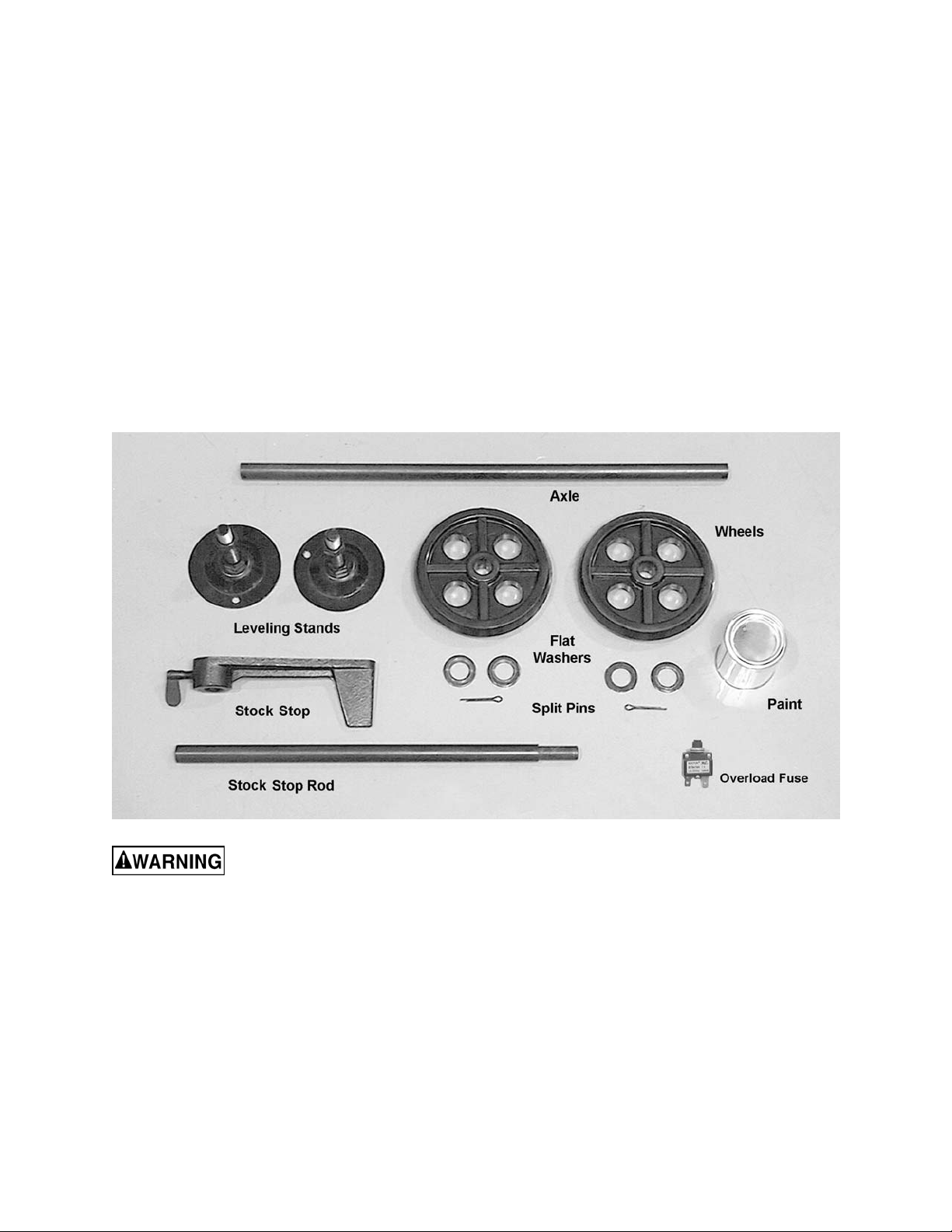
Contents of the Shipping Container
1 Band Saw
2 Leveling Stands (wit h hex nuts)
2 Wheels
1 Axle
4 Flat Washers
2 Split Pins
1 Stock Stop
1 Stock Stop Rod
1 Can White Touch-Up Paint
1 Overload Fuse 10A
1 Owner's Manual
1 Warranty Card
Read and understand the entire contents of this manual before attempting set-up
or operation! Failure t o co mply may cause serious injury.
7
Page 8
Installation and Assembly
Remove all crati ng and plastic from around the
band saw. Remove any lag screws or holding
straps which secure t he band saw to the wood
pallet.
Unpainted areas of the machine have been
treated with a r ust prevent ative. This should be
removed wit h a soft clot h and a mil d solvent . Do
not use paint thinner, lacquer thinner, gasoline
or mineral spirits; these will damage painted and
plastic surf ac es. Do not use an abrasive pad.
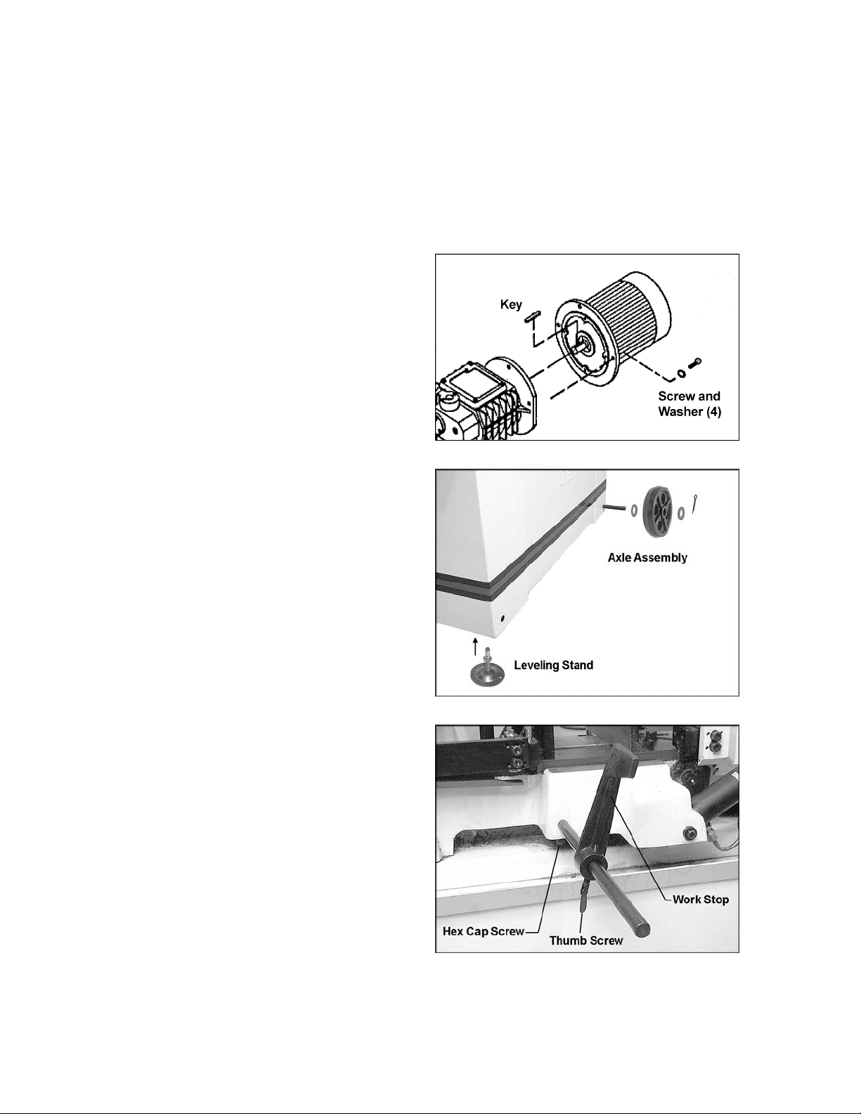
Installing Motor
Mount the motor to the gearbox using the four
M10 x 30 socket head c ap screws and f our M 10
lock washers, through the holes in the motor’s
flange. See F i gure 1. The key in t he m otor shaf t
must line up with the keyway in the gearbox
opening.
Wheels and Leveling Stands
1. Slide the band saw at an angle so that the
edges hang over the sides of the pallet.
2. Insert t he axle thr ough the holes at t he right
end of the band saw cabinet (opposite the
end where the lifting handle is mounted).
See Figure 2.
3. Install a wheel and two f lat washers on eac h
end of the axle. Insert a spli t pi n through the
hole in the axle and bend the ends of the
split pin to secure the wheel on the axle.
4. Install t he two leveling stands at t he left end
of the band saw (the end where the lifting
handle is mounted). See Figure 2. Screw
the leveling stand i nto the hole beneath the
band saw cabinet, and tighten the top hex
nut against the bott om of t he cabi net.
5. The leveli ng st ands can be later adjusted for
level by r otating the stand and re-tighteni ng
the hex nut against the c abinet.
6. Roll the band saw off the pallet.
Figure 1
Figure 2
Stock Stop
1. Insert t he stock stop rod i nto the hol e at t he
front of the base (Figur e 3) .
2. Secure the rod by tightening the hex cap
screw below the casting.
3. Slide the stock stop onto the rod, and
tighten the t humb screw. The stock stop can
be mounted so it faces either direction.
Figure 3
8
Page 9
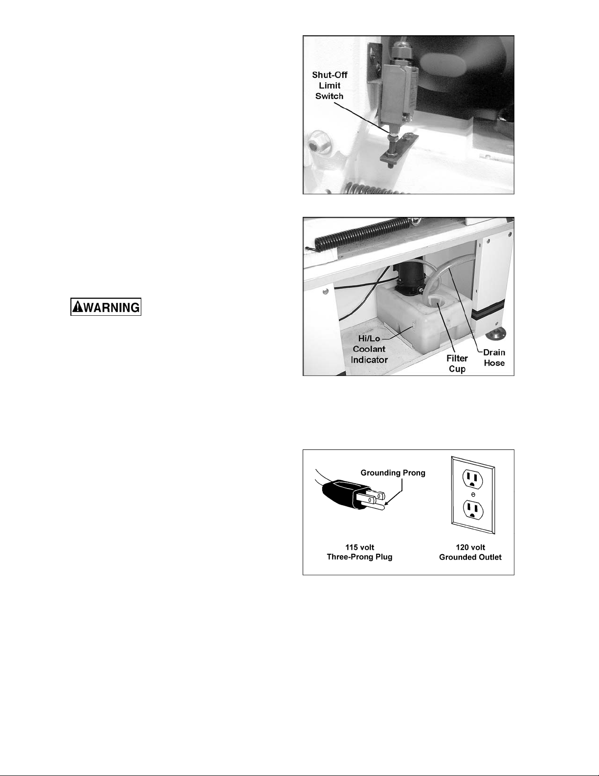
Shut-Off Switch
Remove the screw and hex nuts which hel d the
bow to the base during shipm ent. These should
be retained in case of future transportation of
the Band Saw.
The screw below the limit switch, shown in
Figure 4, has been pre-set at the factor y so that
the switch will contact the screw and stop the
blade after each cutting operation.
Coolant Hose
Before operati ng, the coolant dr ain hose (Figure
5) must be connected to the coolant pan and the
other end of the hose placed into the filter c up in
the tank as shown.
The hose from the coolant pump i s attached to a
valve which should be i nserted into the hole on
the guide assembl y (see Fi gur e 17) .
Grounding Instructions
Electrical connections must
be made by a qualified electrician in
compliance with all relevant codes. This
machine must be properly grounded to help
prevent electrical shock and possible fatal
injury.
This mac hine m ust be grounded. I n the event of
a malfuncti on or break down, groundi ng prov i des
a path of least r esistance f or electric current to
reduce the ri sk of el ectri c shock .
This band saw is pre-wired f or 115 volt and is
equipped with an electric cord having an
equipment-grounding conductor and a
grounding plug si mil ar to that shown in Fi gure 6.
The plug must be inserted int o a matching outl et
that is properly installed and grounded in
accordance with all local codes and ordinances.
Figure 4
Figure 5
Do not modify the plug provided. If it will not fi t
the outlet, have the proper outlet installed by a
qualified elec trician.
Improper connection of the equipmentgrounding conductor can result in a risk of
electric shock. The conductor, with insulation
having an outer surface that is green with or
without yellow stripes, is the equipmentgrounding conduct or. If repai r or replac ement of
the electric cord or plug is necessary, do not
connect the equipment-grounding conductor to a
live terminal.
Check with a qualified electrician or service
personnel if the grounding instructions are not
completely understood, or if in doubt as to
whether the machine is properly grounded.
Figure 6
9
Page 10

115 Volt Operation
As received fr om the f actory, your band saw is
ready to operate at 115 volt power, using an
outlet and a plug that look similar to those
illustrated in Figure 6.
A temporary adapter, which looks like the
adapter illustrated in Figure 7, may be used to
connect this plug to a two-pole receptacle as
shown, if a properly grounded outlet is not
immediately available. The temporary adapter
should only be used until a properly
grounded outlet can be installed by a
qualifi ed el ect rician.
The green colored rigid ear, lug or tab,
extending f rom the adapter must be connec ted
to a permanent ground such as a properly
grounded outlet box, as shown in Figure 7.
Make sure the voltage of your power supply
matches the specif ications on the m otor plate of
the Band Saw.
Conversion to 220 Volt
If 220 volt, single phase operation is desired, t he
following inst r uc tions must be followed:
Figure 7
1. Disconnect machine from power source.
2. Open the electrical box and change the
position of the fuse from the 115V slot to the
220V slot. An el ectrical drawing is included
inside the elect rical box, and is also shown
on page 31 of this manual.
3. The 115V att achm ent plug suppl ied wit h the
band saw must be repl aced with a UL-li sted
plug suitable for 220 volt operation. The
band saw must comply with all local and
national codes after the 220 volt plug is
install ed. The band saw with a 220 volt plug
should only be connected to an outlet
having the same configuration (Figure 8).
No adapter is available or should be used
with the 220 volt plug.
Extens ion cords
If an extensi on c or d is necessary, m ak e sure t he
cord rating i s suitable for the am perage listed on
the machine’s motor plate. An undersized cord
will cause a drop in line voltage resulting in loss
of power and ov erheating. Use only three wire
extension cords that have three-prong
grounding plugs and three- pole recept acles that
accept the mac hine’s pl ug.
Use the chart in Fi gure 9 as a general guide in
choosing the c orrect size cord. If in doubt, use
the next heavi er gauge. The small er the gauge
number, the heavier the cord.
Figure 8
Recomm end ed Ga ug es (A WG ) of Extensi on Co rd s
Extension Cord Length *
25
50
75
100
150
200
Amps
< 5 16 16 16 14 12 12
5 to 8 16 16 14 12 10 NR
8 to 12 14 14 12 10 NR NR
12 to 15 12 12 10 10 NR NR
15 to 20 10 10 10 NR NR NR
21 to 30 10 NR NR NR NR NR
*based on li miting th e lin e voltag e drop to 5V at 150% of th e
rated amp eres.
NR: Not Recommended.
feet
feet
feet
feet
feet
feet
Figure 9
10
Page 11

Adjustments
Vise
There are two set s of hol es in the bed to m ount
the right j aw. The inner hole and slot (A, Figure
10) are used for mit er cuts. The outer hole and
slot (B, Figure 10) are used for square, or 90°
cuts. Figure 10 shows the v ise l ocated i n the “A”
position for miter cuts.
Use only position “A” for miter cuts. If the “A”
position is used for square cuts, it leav es more
blade exposed to the right of the jaw.
Squaring Vise to Blade
1. To set up for square cutting, m ove the right
jaw to “B” position (Figure 10). Place a
machinist’s square on the bed against the
blade and the right vise jaw. The square
should lie along t he entire length of the jaw
and blade without a gap.
2. If adjustment is necessary, slightly loosen
the front screw on the ri ght jaw. Loosen the
hex nut at the center of the right jaw and
adjust jaw so the square li nes up properly.
Figure 10
(fixed jaw shown in “A” posit ion for mitering)
3. Re-tighten the hex nut and the front screw.
4. Loosen the handl e (C, Figure 10) on the l eft
jaw. Move t he left jaw until it c ontacts flush
with the right jaw.
5. Tighten t he handle (C, Figure 10). T he vise
is now set for square cuts.
Positioning the Vise
Keep hands away f rom blade
while adjusting the vise.
1. The workpiece is placed against the fixed
jaw, which has already been squared (see
“Squaring Vise to Blade”), or has been
locked at the appropriate angl e (see “Miter
Cuts”).
2. The vise has a quick-release f eature which
allows fast positioning of the movable jaw
against the workpiece and then a final
tightening with the handle. Lift up on the
quick release lever (D, Figure 11), then
push the movable jaw by hand until it
contacts the workpi ec e.
3. Push down the quick release lever (D,
Figure 11).
4. Turn the lead screw handle (E, Figure 11)
clockwise to cont i nue the t ight eni ng proces s
of the movable jaw until the workpiece is
securely cl am ped.
Figure 11
11
Page 12

5. The qui ck release f uncti on can al so be used
to back off the movabl e jaw when the cut is
finished.
Miter Cuts
1. For miter cuts, move the fixed jaw to the
inner holes, or “A” position, as shown in
Figure 10.
2. Rotate the fixed jaw to the desired angle,
and tighten the center hex nut.
NOTE: There is an angl e scale on the back
side of the bed. This is for reference only.
Check angles with a protractor if greater
precision is needed.
3. Adjust the movable jaw in the manner
described abov e, and tight en the handle (C,
Figure 10).
Setting Downfeed Rate
The downfeed r ate of the blade is i mportant to
band saw performance. Excessive pressure of
blade against the workpiece may break the
blade or stall the saw. In contrast, insufficient
pressure rapidl y dulls the blade.
Turn the valve lever (Figure 12)
countercl ockwise to l ower the bo w. The rat e of
downfeed is cont rolled by the dial setting (Figure
12).
Blade Tension
Blade tension has been set at t he fact ory. W hen
installing a new blade, use the tension handle
(Figure 13) to adjust blade tension (cl ockwise to
tighten). Tension is set properly when the
indicator moves into the “green” area on the
scale.
Figure 12
Blade Tracking
Tracking the blade requires
that the band saw be operating while the
back cover is removed. Use extreme caution.
Blade tracking has been tested at the factory.
Adjustment i s rarely required when the blade i s
used properly and if the blade is correctly
welded. If a tracking problem should occur,
adjust the machine as follows:
1. Raise the bow to its hi ghest position. Make
sure the hydraulic cylinder valve is closed
so the bow remains in place.
2. The blade should be properly tensioned.
NOTE: Keep proper tension on t he blade at
all times using the blade tension adjustment .
3. Open the back wheel cov er.
Figure 13
12
Page 13

While performing the
following steps, keep th e bl ade fro m rubbing
excessively on the shoulder of the wheel.
Excessive rubbing will damage the wheel
and/or the blade.
4. Start the saw. Turn the set screw (Figure
14) to tilt the idler wheel until the blade is
touching the shoulder of the idler wheel.
5. Turn the set screw (Fi gure 14) so the blade
starts to move away from the shoulder of
the wheel; then immediately turn the set
screw in the other direction so the blade
stops; then moves slowly towards the
shoulder. NOTE: This adjustment is
sensitive; do it gradually and in small
increment s all owing the wheel to r espo nd to
the changes.
Keep your fingers clear of
the blade and wheel to avoid injury.
6. Tur n the set scre w to stop the shif ti ng of the
blade on the wheel as it gets closer to the
wheel shoulder. Put a six-inch length of
paper between the blade and the wheel.
See Figure 15. The paper should not be cut
as it passes between the wheel shoulder
and the blade.
7. Turn the set screw a small amount. Repeat
the insertion of the paper between the wheel
shoulder and the bl ade u nti l the paper is cut
into two pieces.
NOTE: You may have to repeat the check
with the paper several times before the
blade and the shoulder cut the paper into
two pieces. Do not hurry the adjustment.
Patience and acc uracy here will pay off wit h
better, more accurate, quieter cutting and
longer machine and blade life.
8. When the paper is cut, back off the set
screw slightl y. This assure s that t he bl ade is
not touching the shoul der of the wheel.
Figure 14
Figure 15
IMPORTANT: If the blade is al lowed to run
against the shoulder of the wheel, it will
wear off the shoulder.
Setting Blade Speed
Rotate the dial (see Figure 16) to the desired
setting – 135, 197 or 256 feet per minute.
Do not change blade speed
during a cutting operat ion.
Figure 16
13
Page 14

Material c hips or shavings are the best i ndicator
of proper bl ade speed and downfeed rate. The
ideal chi p is thin, tightl y curled and warm to the
touch. Chips that range from golden brown to
black indicate excessive force. Blue chips
indicate extreme heat from too high a blade
speed, which will shorten blade life. Thin or
powdered chips indicate insufficient downfeed
rate.
Blade Guides
Loosen the handle (Figure 17) and slide the
guide assembly as close to the workpiece as
possible. This will prevent excessive exposure
of the blade duri ng oper ation.
[NOTE: The handl e (Figure 17) can be adj usted
out of the way. Lift up on the handle and rotate it
on the pin. Release the handle, making sure it
seats itself proper ly on the pin.]
The guide bearings and carbide guide blocks
come pre-adj usted from the fact ory, but should
be inspected frequently and adj ustments made
as needed. For most efficient operation and
maximum accuracy, provide 0.001” clearance
between the blade a nd the gui de bearings. The
bearings will still turn freely with this clearance.
If the clear ance i s incorr ect, the bl ade m ay track
off the drive wheel.
1. Disconnect machine from power source.
Figure 17
2. Loosen the t wo socket head cap scre ws (A,
Figure 18) and move the guide seat (B,
Figure 18) up or down unt i l t he gui de bloc ks
(D, Figure 18) are positioned adequately
across the width of the blade.
3. Loosen the socket head cap screws (C,
Figure 18) on the carbide guide blocks (D,
Figure 18) and shi ft both guide bloc ks until
they place a light pressure on the blade. Retighten the socket head cap screws (C,
Figure 18).
4. The outer guide bearing (E, Figure 18) is
mounted to an eccentric bushing and is
adjustable. Loosen the hex nut (F, Figure
18) and rotate the bearing shaft (G, Figure
18) with a wrench until the bearing (E,
Figure 18) clears the blade by
approxim ately .001”. Do not pinch the blade.
5. Re-tighten hex nut (F, Figure 18).
6. Repeat these steps for the other blade
guide assembly.
Figure 18
14
Page 15

Blade Replacement
A general-use variable-tooth blade is provided
with this metal cutting band saw. Additional
blades can be used and are av ail able from y our
JET distri butor.
The choice of blade pitch is governed by the
thickness of the work to be cut: the thinner the
workpiece, the m ore teeth advised. A minimum
of 3 teeth should engage the workpiece at all
times. If t he teeth of the blade are so far apar t
that they straddle the work, severe damage to
the workpiece and to the blade can result.
1. Disconnect machine from power source.
2. Loosen the handle (Figure 17) and move
the blade guides away from the wheel, as
shown in Figure 19.
3. Raise the bow, making sure the hydraulic
cylinder is closed so the bow will remain
stationary.
4. Open t he back cover, by looseni ng the two
knobs and the four screws on the brackets.
5. Loosen tension on the blade.
Figure 19
6. Remove t he blade f rom between the gui des
and from around the wheels. (Use gloves
when handling sharp bl ades!).
7. Install new blade on wheels, making sure
the teeth point downward in the proper
cutting di rection. See Fi gure 20; also noti ce
the blade dir ection arrow on the f ront of the
bow.
8. Increase blade tension just enough to hold
the blade on the wheels. M ake sure back of
blade rests lightly against the shoulder of
both wheels.
9. Twist bl ade slightly to allow it to slip into the
guides.
10. T he blade should be t ensioned and t racked
properly before use. See “Blade Tension”
and “Blade Tracking” above.
Bow Stop
The stop screw (Fi gure 21) cont rol s the dept h of
fall of t he bow to prevent the bl ade from hitti ng
the bed casting. The stop scre w has been set at
the factory. If future adjustment is needed,
loosen the hex nut and rotate the screw, then retighten the hex nut.
Figure 20
Figure 21
15
Page 16

Operation
Figure 22 shows the contr ol panel functions.
The Emergency Stop shuts do wn all f unctions
on the band saw. The machine will not start if
the emergenc y stop is still engaged. T o start the
machine, twist t he emergency stop butt on until it
pops back out.
IMPORTANT: When cutting magnesium, never
use soluble oils or em ulsions (oil-water mix) as
water will greatly intensify any accidental
magnesium chi p fi re. S ee your i ndustri al cool ant
supplier for specific coolant recommendations
when cutti ng magnesium.
General Operating Procedure:
1. Give machine an overall inspection. Verify
that all guards, cov ers, etc. are in plac e and
in working order, the blade is tensioned
properly and t he toot h dir ection m atches t he
arrow on the bow. Check that the blade
guides are set correctly, and also the wire
brush.
2. Place workpiece in vise and tighten vise.
The workpiece should be fitted directly
between the jaws without adding other
objects.
Figure 22
When the workpiece to be cut is a profiled
section, fl at piece or special shape, ref er to
the examples sho wn in Figur e 23 for pr oper
clamping positions. The top row shows
acceptable clamping positions, the bottom
row sho w s unacceptabl e posit ions.
If the thic kness of the profiled section i s very
thin, a piece which duplicates the profile
should be fitted inside the workpiece itself,
to prevent the workpiece being crushed
between the jaws.
Never hold a workpiece by
hand when cu tting it – t he workp iece should
be firmly secured in the vise. Do not reach
into the cutting area during cutting
operations.
3. Rotate t he speed dial to the desir ed setti ng.
Do not rotate the speed dial during a
cutting operati on .
4. Set a suitable downfeed rate for that
operation on the cylinder dial.
5. Push the start button to start the blade
circulating.
6. Turn on the coolant flow.
Figure 23
16
Page 17

7. Open t he valve on the hydrauli c cylinder to
allow the bow to desce nd in a gradual and
controlled manner.
8. The m achine will shut off at the completi on
of the cut. Turn off the coolant flow, and
remove the workpiec e.
9. Return the bow to vertical position for the
next c u t.
Maintenance
Before doing maintenance
on the machine, disconnect it from the
electrical supply by pulling out the plug or
switching off the main switch. Failure to
comply may cause seriou s injury.
Clean the band saw regularly after each day’s
work. Clear metal shavings with the provided
brush, do not use your hands. Do not use
compressed air.
To prevent corrosion of machined surfaces
when a soluble oil is used as coolant, pay
particular attention to wiping dry the surfaces
where fluid acc um ulates and does not evaporate
quickly, such as between the machi ne bed and
vise.
If the power cord is worn, cut, or damaged in
any way, have it repl ac ed immediately.
All ball bearings are perm anentl y lubri cated and
sealed. They require no further lubric ation.
Grease the vise l ead screw as needed.
Place a thin coat of oil on the bed surface on
which the vise jaw slides.
Maintain coolant level. Low coolant level can
cause foaming and high blade temperatures.
Replace dirt y coolant; dirty or weak coolant can
clog the pump, cause crooked cuts, a low
cutting rat e and/or permanent blade damage. To
fill the tank, remove the filter cup and pour
coolant i nto the hol e. A “Hi/Lo” mark on t he tank
indicates proper level (see Figure 5).
Maintain oil level in the gear box, using SAE No.
10. To check level of the gear box oil, place bow
in down posit ion so that oil drains do wn. Check
level in sight glass on side of gear casing.
Correct l ev el is the dot in t he mi ddl e of t he si ght
glass. Figure 24 shows the locations of the fill
hole, sight gl ass and drain plug for the gear box.
Completely drai n and refill the gear box oil once
a year.
Figure 24
17
Page 18

Troubleshooting
Trouble Probable Cause Remedy
Motor will not start. No incoming power. Check plug connection.
Blown electri c al panel fuses. Replace fuses.
Overload trips
frequently.
Band Saw vibrates
excessively.
Miter cuts not
accurate.
Thermal overload has tripped.
Defective motor, switch, power cable,
or plug.
Motor is overheating. Check that motor air intakes are clear.
Downfeed rate too f ast . Reduce downfeed rat e.
Motor is faulty.
Base on uneven surfac e. Adjust base for even support.
Saw blade has cracks. Replace blade immediately.
Too heavy a cut.
Setting of the miter stops is not
correct.
Blade is worn, cutting crooked. Replace blade.
Wait several minutes for overload to
reset itself.
Qualified electrician/service personnel
should inspect these i tems.
Motor should be i nspect ed by
qualified elec trician/service personnel.
Reduce downfeed rate and blade
speed.
Loosen the screws and adjust the
stops to correct positions. Use an
adjustable square or protractor t o
check angle setti ngs.
Cuts not square. Feed pressure too great . Decrease feed pressure.
Adjust stop until blade is square with
vise.
Check Machinist’s Handbook for
recommended blade type.
Re-adjust these. See page 14.
Check positi oning and clamping in the
vise.
Check Machinist’s Handbook for
blade recommendations.
Finished surfac e of
workpiece is rough,
unsatisfactory.
90° angle stop is not set c orrec tly.
Incorrect blade toothing in relation t o
workpiece.
Blade is worn, cutting crooked. Replace blade.
Incorrect adjustment of bearing
guides and guide assembly.
Workpiec e inc or r ectly posi tioned in
vise.
Poor blade tensi on. Check and correct if needed.
Blade is dull. Replace blade.
Improper bl ade for cutting operation.
Downfeed rate too f ast . Reduce downfeed rat e.
Blade tension too low. Increase blade tensi on.
18
Page 19

Trouble Probable Cause Remedy
Excessive blade
breakage.
Premature Blade
Dulling.
Incorrect blade tension. Adjust accordingly (see page 12).
Incorrect blade speed or downf eed
rate.
Workpiec e loose i n vi se. Clamp workpiece securely.
Blade rubs on wheel shoulder. Adjust blade trac ki ng.
Teeth too coarse f or mat eri al.
Teeth in contact with workpiece
before saw is started.
Blade guides are misal igned. Adjust as needed. See page 14.
Blade too thick for wheel diameter. Use thinner blade.
Cracking at weld; poor annealing of
blade.
Teeth too coarse. Use finer toot h blade.
Blade speed too fast. Reduce speed.
Inadequate downf eed rate. Adjust cylinder dial setting as needed.
Adjust acccordingly.
Use appropriate bl ade for material
being cut.
Start motor before blade contacts
workpiece.
Replace blade.
Scale: Reduce speed and incr ease
Hard spots or scale on mat eri al.
Work hardeni ng of material
(especially stainless steel)
Blade installed backwards.
Insuffici ent blade tension. Adjust as needed.
downfeed rate. Hard S pots: Increase
downfeed rate.
Increase downfeed r ate.
Remove blade, twist inside-out and
re-install.
Replacement Parts
Replacement par ts are li sted on the f ollowing page s. To order parts or reac h our servi ce depar tm ent, call
1-800-274-6848 Monday through F riday ( see our websit e f or business hours, www.jett ools.com). Hav ing
the Model Num ber and S eri al Num ber of y our machi ne avail abl e when you cal l will allow us to serve you
quickly and acc ur ately.
19
Page 20

Base Assembly
20
Page 21

Bow Assembly
202
21
Page 22

Parts List: HBS-814GH Band Saw
Index No. P art No. Description Size Qty
1 ............... HBS814GH-001 ............. Base ............................................................................................... 1
2 ............... HBS814GH-002 ............. Stand Complete Assembl y .............................................................. 1
2-1............ HBS 814GH-002-1 .......... Coolant Pan .................................................................................... 1
2-2............ HBS 814GH-002-2 .......... Leg ( Right) ...................................................................................... 1
2-3............ HBS 814GH-002-3 .......... Leg ( Left) ........................................................................................ 1
2-4............ HBS 814GH-002-4 .......... Panel .............................................................................................. 1
3 ............... HBS814GH-003 ............. Vise Jaw Bracket (Front) ................................................................. 1
4 ............... HBS814GH-4 ................. Washer ........................................................10 x 25 x 2.................. 2
5 ............... HBS814GH-005 ............. Carriage Bolt ................................................1/2"-12 x 2” ................. 1
6 ............... TS-0209071 ................... Socket Head Cap Screw ..............................3/8"-1 6 x 1-1/2 "L ......... 1
7 ............... 6290483......................... Hex Nut ........................................................1/2”-12........................ 1
8 ............... HBS814GH-063 ............. Washer ........................................................12 x 28 x 2.................. 2
9 ............... HBS814GH-009 ............. Hex Cap Scre w ............................................1/2"-12 x 2"L ............... 1
10 ............. HBS814GH-010 ............. Vise Jaw Bracket (Rear) .................................................................. 1
11 ............. HBS814GH-011 ............. Miter Clamp Bolt .............................................................................. 1
13 ............. HBS814GH-013 ............. Handle ............................................................................................ 1
14 ............. HBS814GH-014 ............. Crank .............................................................................................. 1
15 ............. HBS814GH-015 ............. Washer ........................................................12 x 23 x 2.................. 1
16 ............. HBS814GH-016 ............. Thrust Flange .................................................................................. 1
17 ............. TS-0267051 ................... Socket Set Screw .........................................1/4"-20 x 1/2"L ............ 1
18 ............. HBS814GH-018 ............. Acme Nut ..................................................... .................................. 1
19 ............. HBS814GH-019 ............. Acme Screw .................................................................................... 1
20 ............. HBS814GH-020 ............. Pin ...............................................................5 x 34L ....................... 2
21 ............. HBS814GH-021 ............. Vise Cam ........................................................................................ 1
22 ............. TS-
23 ............. HBS814GH-023 ............. Washer ........................................................8 x 25 x 3 ................... 2
24 ............. HBS814GH-024 ............. Shipping Bracket ............................................................................. 1
25 ............. TS-0060081 ................... Hex Cap Screw ............................................3 /8 "- 1 6 x 1-3/4 " ........... 1
26 ............. TS-0060091 ................... Hex Cap Screw ............................................3 /8 "- 1 6 x 2" ................. 1
27 ............. HBS814GH-285 ............. Washer ........................................................10 x 20 x 2.................. 1
28 ............. TS-0561031 ................... Hex Nut ........................................................3/8”-16........................ 2
29 ............. HBS814GH-029 ............. Knob ............................................................................................... 1
30 ............. HBS814GH-030 ............. Shaft ............................................................................................... 1
37 ............. HBS814GH-037 ............. Fiber washer ................................................................................... 8
40 ............. HBS814GH-040 ............. Cover .............................................................................................. 1
41 ............. TS-081C022 .................. Phillips Pan Head Machine Screw ................#10-24 x 3/8"L ............ 2
50 ............. HBS814GH-050 ............. Stop Block ....................................................................................... 1
51 ............. HBS814GH-051 ............. Thumb Screw .................................................................................. 1
52 ............. HBS814GH-052 ............. Stock Stop Rod ............................................................................... 1
53 ............. TS-0051031 ................... Hex Cap Screw ............................................5 /1 6 "- 1 8 x 3/4"L .......... 1
54 ............. TS-0267061 ................... Socket Set Screw .........................................1/4"-20 x 5/8"L ............ 1
55 ............. HBS814GH-055 ............. Cylinder Lower Support ................................................................... 1
56 ............. TS-0060061 ................... Hex Cap Screw ............................................3 /8 "- 1 6 x 1-1/4 "L ......... 2
57 ............. HBS814GH-285 ............. Washer ........................................................10 x 20 x 2.................. 2
58 ............. HBS814GH-058 ............. Bearing ........................................................................................... 1
59 ............. HBS814GH-059 ............. Washer ........................................................................................... 1
60 ............. HBS814GH-060 ............. Spring ............................................................................................. 1
61 ............. HBS814GH-061 ............. Pivot Shaft....................................................................................... 1
62 ............. HBS814GH-062 ............. Bushing ........................................................................................... 1
63 ............. HBS814GH-063 ............. Washer ........................................................12 x 28 x 2.................. 2
64 ............. 6290483......................... Hex Nut ........................................................1/2"-12 ....................... 2
69 ............. HBS814GH-069 ............. Bracket............................................................................................ 1
70 ............. TS-0060031 ................... Hex Cap Screw ............................................3 /8 "- 1 6 x 3/4"L ............ 1
71 ............. HBS814GH-071 ............. Washer ........................................................10 x 25 x 3.................. 1
76 ............. HBS814GH-076
77 ............. TS-0050011 ................... Hex Cap Screw ............................................1 /4 "- 2 0 x 1/2"L ............ 1
81 ............. TS-081C022 .................. Phillips Pan Head Machine Screw ................#10-24 x 3/8"L ............ 2
0051021 ................... Hex Cap Scre w ............................................5 /1 6 " -1 8 x 5/8"L .......... 2
............. Screen ............................................................................................ 1
22
Page 23

Index No. P art No. Description Size Qty
82 ............. TS-069204 ..................... Flat Washer..................................................#10 ............................. 2
83 ............. HBS814GH-083 ............. Scale ............................................................................................... 1
84 ............. HBS814GH-084 ............. Spring ............................................................................................. 1
85 ............. HBS814GH-085 ............. Spring Adjusting Screw ................................................................... 1
86 ............. TS-0051031 ................... Hex Cap Screw ............................................5 /1 6 "- 1 8 x 3/4"L .......... 1
87 ............. HBS814GH-087 ............. Washer ........................................................8 x 23 x 2 ................... 1
88 ............. HBS814GH-088 ............. Spring Handle Bracket..................................................................... 1
89 ............. HBS814GH-092 ............. Washer ........................................................10 x 23 x 2.................. 1
90 ............. TS-0561031 ................... Hex Nut ........................................................3/8-16 ......................... 1
92 ............. HBS814GH-092 ............. Washer ........................................................10 x 23 x 2.................. 3
93 ............. TS-0209061 ................... Socket Head Cap Screw ..............................3/8" -1 6 x 1-1/4 " L ......... 3
96 ............. HBS814GH-096 ............. Rear Pivot Bracket .......................................................................... 1
98 ............. TS-0267051 ................... Socket Set Screw .........................................1/4"-20 x 1/2"L ............ 1
99 ............. HBS814GH-099 ............. Cylinder Upper Support ................................................................... 1
100 ........... HBS814GH-100 ............. Shaft .............................................................................................. 1
101 ........... TS-0060051 ................... Hex Cap Scre w ............................................3/8"-1 6 x 1"L ............... 2
102 ........... HBS814GH-4 ................. Washer ........................................................10 x 25 x 2.................. 2
103 ........... HBS814GH-103 ............. Cylinder Complete Set..................................................................... 1
105 ........... HBS814GH-105 ............. Cross Round Head Screw ............................1/4"-20 x 5/8"L ............ 4
106 ........... HBS814GH-106 ............. Washer ........................................................6.3 x 19 x 1.5 .............. 4
107 ........... HBS814GH-107 ............. Pump ...........................................................1/8HP,110/220V,1PH . 1
108 ........... HBS814GH-108 ............. Close Nipple .................................................3/8"PT ........................ 1
109 ........... HBS814GH-109 ............. Hose ............................................................OD12 x ID8 x 2000 ..... 1
110 ........... HBS814GH-110 ............. Hose Clip .....................................................5/8" ............................ 3
111 ........... TS-081C022 .................. Phillips Pan Head Machine Screw ................#10-24 x 3/8"L ............ 3
113 ........... HBS814GH-092 ............. Washer ........................................................10 x 23 x 2.................. 2
114 ........... TS-0209031 ................... Socket Head Cap Screw
118 ........... HBS814GH-118 ............. Hose ............................................................OD16 x ID13 x 260 ..... 1
................. HBS814GH-118N .......... Hose ............................................................OD24 x ID1 8 .5 x 650 .. 1
119 ........... HBS814GH-119 ............. Coolant Tank ................................................................................... 1
126 ........... HBS814GH-126 ............. Washer ........................................................5/8" x 40 x 3" .............. 4
127 ........... HBS814GH-127 ............. Wheel ............................................................................................. 2
128 ........... 5519932......................... Cotter Pin .....................................................3 x 25L ....................... 2
129 ........... HBS814GH-129 ............. Wheel Rod ...................................................................................... 1
133 ........... 6290483......................... Hex Nut ........................................................1/”2-12........................ 2
134 ........... HBS814GH-134 ............. Coaster of Stand ..........................................1 /2 " ............................ 2
137 ........... TS-0680041 ................... Washer ........................................................3/8" ............................ 8
138 ........... TS-0060051 ................... Hex Cap Scre w ............................................3/8"-1 6 x 1"L ............... 8
139 ........... HBS814GH-139 ............. Handle ............................................................................................ 1
140 ........... HBS814GH-140 ............. Flat Cross Head Screw .................................M5-0.8 x 12L .............. 1
141 ........... TS-1523051 ................... Socket Set Screw .........................................M6-1 x 15L ................. 4
142 ........... HBS814GH-142 ............. Door Clip Lower .............................................................................. 2
143 ........... HBS814GH-143 ............. Washer ........................................................6.3 x 16 x 1.5 .............. 4
144 ........... TS-0050011 ................... Hex Cap Scre w ............................................1/4"-2 0 x 1/2"L ............ 4
146 ........... HBS814GH-146 ............. Body Frame .................................................................................... 1
147 ........... TS-0720091 ................... Lock Was h e r ................................................3/8" ............................ 4
148 ........... TS-0060061 ................... Hex Cap Scre w ............................................3/8"-1 6 x 1-1/4 "L ......... 4
152 ........... HBS814GH-152 ............. Upper Bracket hold down ................................................................ 1
153 ........... HBS814GH-285 ............. Washer ........................................................10 x 20 x 2.................. 2
154 ........... TS-0060051 ................... Hex Cap Scre w ............................................3/8"-1 6 x 1" ................. 2
155 ........... HBS814GH-155 ............. Blade.............................................0.032" x 3/4" x 2464L x 5-8T" ...... 1
156 ........... HBS814GH-156 ............. Drive Wheel .................................................................................... 1
157 ........... TS-0267051 ................... Socket Set Screw .........................................1/4"-20 x 1/2"L ............ 1
158 ........... 5519933......................... C-Retainer Ring ...........................................S2 5 ............................ 1
159 ........... HBS814GH-159 ............. Bl
160 ........... HBS814GH-143 ............. Washer ........................................................6.3 x 16 x 1.5 .............. 4
161 ........... HBS814GH-161 ............. Knob ............................................................................................... 4
163 ........... HBS814GH-163 ............. Clamp Block Guide Arm .................................................................. 1
164 ........... TS-1550071 ................... Flat Washer..................................................M10 ............................ 1
ade Back Cover............................................................................ 1
..............................3/8"-16 x 3/4"L ............ 2
23
Page 24

Index No. P art No. Description Size Qty
165 ........... HBS814GH-165 ............. Grip ..............................................................M10-1.5 x 52L ............ 1
166 ........... HBS814GH-166 ............. Idler Wheel Assembly ...................................................................... 1
166-1 ........ HBS814GH-166-1 .......... Idler Wheel ...................................................................................... 1
166-2 ........ HBS814GH-166-2 .......... Be aring Cover ................................................................................. 1
166-3 ........ HBS814GH-211 ............. Washer ........................................................8 x 18 x 1.5 ................. 1
166-4 ........ TS-0051031 ................... Hex Cap Screw ............................................5 /1 6 " -1 8 x 3/4"L .......... 1
166-5 ........ HBS814GH-166-5 .......... Cross Round Head Scre w ............................#10-24 x 3/8"L ............ 3
166-6 ........ HBS814GH-166-6 .......... Bushing ........................................................................................... 1
166-8 ........ BB-6202ZZ .................... Bearing ........................................................6202ZZ....................... 2
166-9 ........ HBS814GH-166-9 .......... Bushing ........................................................................................... 1
173 ........... HBS814GH-173 ............. Shaft Assembly ............................................................................... 1
173-1 ........ HBS814GH-173-1 .......... Sliding Plate Draw Block ................................................................. 1
173-2 ........ HBS814GH-173-2 .......... Blade Wheel Shaft........................................................................... 1
173-3 ........ HBS814GH-173-3 .......... Pin ...............................................................4 x 22L ....................... 1
174 ........... HBS814GH-174 ............. Control Box Assembly ..................................................................... 1
174-1 ........ HBS814GH-174-1 .......... C ontrol Box ..................................................................................... 1
174-2 ........ HBS814GH-174-2 .......... Control Plate ................................................................................... 1
174-3 ........ HBS814GH-174-3 .......... Label for Name Plate ....................................................................... 1
174-4 ........ TS-1533042 ................... Phillips Pan Head Machine Screw ................M5-0.8P*12L .............. 4
174-5 ........ TS-1550041 ................... Flat Washer..................................................M6 .............................. 2
174-6 ........ TS-1482031 ................... Hex Cap Screw ............................................M 6 -1 .0 x 15L .............. 2
175 ........... TS-0561031 ................... Hex Nut ........................................................3/8-16 ......................... 1
176 ........... HBS814GH-176 ............. Sliding Plate .................................................................................... 2
177 ........... HBS814GH-177 ............. Blade Tension Slide Bloc k ............................................................... 1
178 ........... TS-0270071 ................... Socket Set Screw .........................................5/16"-18 x 3/4"L .......... 1
179 ........... TS-0051071 ................... Hex Cap Scre w ............................................5/16"- 1 8 x 1-1/2 "L ....... 2
180 ........... HBS814GH-180 ............. Washer ........................................................8 x 12 x 2 ................... 2
181 ........... TS-0051031 ................... Hex Cap Screw ............................................5/16"-18 × 3/4"L .......... 4
182 ........... TS-0720081 ................... Lock Washer ................................................5/16"........................... 4
186 ........... HBS814GH-200 ............. Phillips Pan Head Machine Screw ................1/4"-20 x 3/8"L ............ 1
187 ........... HBS814GH-187 ............. Blade Guard .................................................................................... 1
190 ........... HBS814GH-190 ............. Blade Guide Assembly .................................................................... 1
190-1 ........ HBS814GH-190-1 .......... Blade Guide .................................................................................... 1
190-2 ........ HBS814GH-190-2 .......... Adjustable Bracket (Front) ............................................................... 1
190-3 ........ HBS814GH-211 ............. Washer ........................................................8 x 18 x 1.5 ................. 2
190-4 ........ TS-0720081 ................... Lock Washer ................................................5/16"........................... 2
190-5 ........ TS-0208071 ................... Socket Head Cap Screw ..............................5/16"-18 x 1-1/4 ” L ....... 2
190-6 ........ TS-1523031 ................... Socket Set Screw .........................................M6-1P*10L ................. 2
190-7 ........ TS-1503041 ................... Socket Head Cap Screw ..............................M6 -1 x 15L ................. 2
190-8 ........ TS-1540071 ................... Hex Nut ........................................................M10-1.5 x P1 .............. 2
190-9 ........ TS-2361101 ................... Lock Washer ................................................M10 ............................ 2
190-10 ...... HBS814GH-190-10 ........ Carbide Guide ................................................................................. 2
190-11 ...... TS-0207041 ................... Socket Head Cap Screw ..............................1/4" -2 0 x 3/4"L ............ 2
190-12 ...... HBS814GH-190-12 ........ Top Guide Left ................................................................................ 1
190-13 ...... TS-1503021 ................... Socket Head Cap Screw ..............................M6-1 x 10 ................... 1
191 ........... HBS814GH-191 ............. Eccentric shaft Assembly................................................................. 2
191-1 ........ HBS814GH-191-1 .......... Eccentric shaft................................................................................. 2
191-2 ........ BB-608ZZ ...................... Bearing ........................................................608ZZ......................... 2
191-3 ........ 5515607......................... C-Retaining Ring ..........................................S10 ............................ 2
192 ........... HBS814GH-192 ............. Bearing Shaft Assembly .................................................................. 2
192-1 ........ HBS814GH-192-1 .......... Bearing Shaft .................................................................................. 2
192-2 ........ BB-608ZZ ...................... Bearing ........................................................608ZZ......................... 2
192-3 ........ 5515607......................... C-Retaining Ring ..........................................S10 ............................ 2
198 ........... HBS814GH-198 ............. Brush Assembly .............................................................................. 1
198-1 ........ HBS814GH-198-1 .......... Brush Support ................................................................................. 1
198-2 ........ HBS814GH-198-2 .......... Brush .............................................................................................. 1
198-3 ........ HBS814GH-198-3 .......... Bushing ........................................................................................... 1
198-4 ........ HBS814GH-285 ............. Washer ........................................................10 x 20 x 2.................. 1
198-5 ........ TS-1523031 ................... Socket Set Screw .........................................M6-1 x 10L ................. 1
24
Page 25

Index No. P art No. Description Size Qty
198-6 ........ HBS814GH-198-6 .......... Bushing ........................................................................................... 1
200 ........... HBS814GH-200 ............. Phillips Pan Head Machine Screw ................1/4"-20 x 3/8"L ............ 2
201 ........... TS-0680021 ................... Flat Washer..................................................1/4" ............................ 2
202 ........... HBS814GH-202 ............. Blade Guide Assembly .................................................................... 1
202-1 ........ HBS814GH-202-1 .......... Blade Adjustabl e ............................................................................. 1
202-5 ........ TS-1540071 ................... Hex Nut ........................................................M10-1.5 x P1 .............. 2
202-6 ........ TS-2361101 ................... Lock Washer ................................................M10 ............................ 2
202-13 ...... HBS814GH-202-13 ........ Carbide Guide ................................................................................. 2
202-14 ...... TS-0207041 ................... Socket Head Cap Screw ..............................1/4" -2 0 x 3/4"L ............ 2
202-15 ...... HBS814GH-202-15 ........ Top Guide Right .............................................................................. 1
211 ........... HBS814GH-211 ............. Washer ........................................................8 x 18 x 1.5 ................. 2
212 ........... TS-0720081 ................... Lock Washer ................................................5/16"........................... 2
213 ........... TS-0208121 ................... Socket Head Cap Screw ..............................5/16"- 1 8 x 2-1/2 "L ....... 2
231 ........... HBS814GH-231 ............. Handle Body ................................................................................... 1
232 ........... HBS814GH-232 ............. Blade Tension Bar ........................................................................... 1
233 ........... HBS814GH-233 ............. Knob ............................................................................................... 2
234 ........... HBS814GH-234 ............. Indicator plate ................................................................................. 1
235 ........... HBS814GH-235 ............. Thrust Rearing .............................................10 x 25 x 2.................. 2
238 ........... HBS814GH-238 ............. Sleeve ............................................................................................. 1
239 ........... HBS814GH-239 ............. Spring ..........................................................23 x 12.2 x 1.5t ........... 8
240 ........... HBS814GH-240 ............. Scale ............................................................................................... 1
241 ........... HBS814GH-241 ............. Rivet ............................................................Ø2 x 6 ........................ 2
249 ........... HBS814GH-249 ............. Spring ............................................................................................. 1
271A ........ HBS814GH-271A ........... Electrical Control Box ..................................................................... 1
272 ........... HBS814GH-272 ............. Cable Clamp ................................................................................... 2
281 ........... TS-081F052 ................... Pan Head Phillips Screw ..............................1 /4 "- 2 0 x 3/4"L ............ 8
282 ........... HBS814GH-143 ............. Washer ........................................................6.3 x 16 x 1.5 ............ 16
283 ........... TS-0570011 ................... Hex Nut ........................................................1/4-20 ......................... 8
284 ........... TS-0060051 ................... Hex Cap Scre w ............................................3/8"-1 6 x 1"L ............... 8
285 ........... HBS814GH-285 ............. Washer ........................................................10 x 20 x 2................ 16
286 ........... TS-0561031 ................... Hex Nut ........................................................3/8-16 ......................... 8
287 ........... HBS814GH-287 ............. Valve Assembly ............................................................................... 1
287-1 ........ HBS814GH-287-1 .......... Micro Control Block ......................................PT1/8" x 1/4" .............. 1
287-2 ........ HBS814GH-287-2 .......... Valve ............................................................PT1/8" x 1/8" .............. 1
287-3 ........ HBS814GH-287-3 .......... Jet Pipe ........................................................................................... 1
287-4 ........ HBS814GH-287-4 .......... O-Ring .........................................................8 x 4.5 x 1.9 ................ 1
290 ........... HBS814GH-105 ............. Cross Socket Head Screw ............................1/4"-20 x 5/8"L ............ 2
291 ........... HBS814GH-143 ............. Washer ........................................................6.3 x 16 x 1.5 .............. 2
292 ........... HBS814GH-292 ............. Support Pl ate .................................................................................. 1
400 ........... HBS814GH-400 ............. Limit Plate ....................................................................................... 1
401 ........... HBS814GH-143 ............. Washer ........................................................6 x 16 x 1.5mm ........... 2
402 ........... TS-0207031 ................... Socket Head Cap Screw ..............................1/4”-2 0 x 5/8” .............. 2
403 ........... TS-0570011 ................... Nut ...............................................................1/4”............................. 1
404 ........... TS-0208071 ................... Socket Head Cap Screw ..............................5/16”-18 x 1-1/4” ......... 1
405 ........... HBS814GH-405 ............. Bracket............................................................................................ 1
406 ........... TS-1550041 ................... Washer ........................................................M6 .............................. 2
407 ........... TS-133032 ..................... Pan Head Phillips Scr ew ..............................M5-0 .8 x 10 ................ 2
408 ........... HBS814GH-408 ............. Limit Switch ..................................................................................... 1
409 ........... TS-1550021 ................... Washer ........................................................M4 .............................. 2
410 ........... HBS814GH-410 ............. Pan Head Phil lips Screw ..............................M 4 -0 .4 x 30L .............. 2
800 ........... HBS814GH-800 ............. Gear Box Assembly ......................................................................... 1
801 ........... HBS
802 ........... HBS814GH-802 ............. Motor.................................................1HP, 110/220V, 60HZ,1P H ..... 1
................. HBS814GH-MF .............. Motor Fan (not show) ...................................................................... 1
................. HBS814GH-MFC ........... Motor Fan Cover (not show) ............................................................ 1
803 ........... TS-1505041 ................... Socket Head Cap Screw ..............................M10-1 .5 x 30L ............ 4
804 ........... TS-2361101 ................... Lock Washer ................................................M10 ............................ 4
814GH-801 ............. Key ..............................................................6 x 6 x 40L.................. 1
25
Page 26

Gear Box Assembly
26
Page 27

Parts List: Gear Box Assembly
Index No. Part No. Descripti on Size Qty
.................. HBS814GH-800 ............ Gear Box Assembly ......................................................................... 1
800-1 ......... HBS814GH-800-1 ......... Gear Box Enclosure ........................................................................ 1
800-2 ......... HBS814GH-800-2 ......... Gear Box Cover .............................................................................. 1
800-3 ......... HBS814GH-800-3 ......... Speed-Changing Gear Shaft ........................................................... 1
800-4 ......... HBS814GH-800-4 ......... Speed Lever .................................................................................... 1
800-5 ......... HBS814GH-800-5 ......... Spring ............................................................................................. 1
800-6 ......... SB-8MM ....................... Steel Ball ......................................................8 ................................. 1
800-7 ......... HBS814GH-800-7 ......... Speed Indi c ator Di al ....................................................................... 1
800-8 ......... TS-1502071 .................. Socket Head Cap Screw ..............................M5 -0.8 x 28L .............. 1
800-9 ......... HBS814GH-800-9 ......... Worm Shaft ..................................................................................... 1
800-10 ....... HBS814GH-800-10 ....... Speed-Changing Rod ...................................................................... 1
800-11 ....... HBS814GH-800-11 ....... Speed-Changing Key ...................................................................... 1
800-12 ....... HBS814GH-800-12 ....... Torsion Spring ................................................................................. 1
800-13 ....... HBS814GH-800-13 ....... Pin ...............................................................3 x 10L ....................... 2
800-14 ....... HBS814GH-800-14 ....... Gear................................................................................................ 1
800-15 ....... HBS814GH-800-15 ....... Gear................................................................................................ 1
800-16 ....... HBS814GH-800-16 ....... Gear................................................................................................ 1
800-17 ....... HBS814GH-800-17 ....... Washer ........................................................................................... 4
800-18 ....... HBS814GH-800-18 ....... Bushing Bracket .............................................................................. 1
800-19 ....... PWBS14-123 ................ C-Retainer Ring ...........................................R35 ............................ 2
800-20 ....... TS-1523011 .................. Socket Set Screw .........................................M6-1 x 6L ................... 2
800-21 ....... HBS814GH-800-29
800-22 ....... HBS814GH-800-22 ....... Cover .............................................................................................. 1
800-23 ....... HBS814GH-800-23 ....... Gear Shaft....................................................................................... 1
800-24 ....... HBS814GH-800-24 ....... Gear................................................................................................ 1
800-25 ....... HBS814GH-800-25 ....... Gear................................................................................................ 1
800-26 ....... HBS814GH-800-26 ....... Gear................................................................................................ 1
800-27 ....... 6291479 ....................... Key ..............................................................5 x 5 x 32L .................. 1
800-28 ....... 5513018 ....................... C-Retainer Ring ...........................................S1 7 ............................ 2
800-29 ....... HBS814GH-800-29 ....... Bearing ........................................................6003LLB ..................... 1
800-30 ....... HBS814GH-800-30 ....... Bearing ........................................................6007LLB ..................... 1
800-31 ....... HBS814GH-800-31 ....... C-Retainer Ring ...........................................R62 ............................ 1
800-33 ....... HBS814GH-800-33 ....... Oil Seal ........................................................62 x 35 x 8.................. 1
800-37 ....... HBS814GH-800-37 ....... Drive Gea r Shaft ............................................................................ 1
800-38 ....... HBS814GH-800-38 ....... Worm Gear ..................................................................................... 1
800-39 ....... 5519933 ....................... C-Retainer Ring ...........................................S2 5 ............................ 2
800-40 ....... 1020A-292 .................... Key ..............................................................6 x 6 x 2 0L.................. 2
800-41 ....... HBS814GH-800-41 ....... Bearing ........................................................60205LLB ................... 2
800-42 ....... HBS814GH-800-42 ....... Bearing Spacer ............................................................................... 1
800-43 ....... HBS814GH-800-43 ....... Cover .............................................................................................. 1
800-44 ....... HBS814GH-800-44 ....... O-Ring .........................................................35 x 29 x 3.................. 2
800-45 ....... TS-1533042 .................. Cross Round Head Screw ............................M5-0.8 x 13L .............. 3
800-46 ....... HBS814GH-800-46 ....... Plug .............................................................PT3/8" ........................ 1
800-47 ....... TS-1503051 .................. Socket H
800-48 ....... HBS814GH-800-48 ....... Vent Plug ........................................................................................ 1
800-49 ....... HBS814GH-800-49 ....... Scale ............................................................................................... 1
800-50 ....... HBS814GH-800-50 ....... Rivet ............................................................2 x 4 ........................... 2
800-51 ....... HBS814GH-800-51 ....... Bearing Cover ................................................................................. 1
800-52 ....... TS-1533032 .................. Cross Round Head Screw ............................M5-0.8 x 10L .............. 3
800-53 ....... HBS814GH-800-53 ....... Gear Box Gasket ............................................................................. 1
800-54 ....... HBS814GH-800-54 ....... Plug .............................................................PT1/4" ........................ 1
800-55 ....... HBS814GH-800-55 ....... Oil level gauge .............................................19 ............................... 1
800-56 ....... HBS814GH-800-56 ....... O- Ring ........................................................15.8 x 2.4b ................. 1
800-57 ....... HBS814GH-800-57 ....... C-Retainer Ring ...........................................R20 ............................ 1
....... Bearing ........................................................6003LLB ..................... 2
ead Cap Screw ..............................M6-1 x 20L ................. 4
27
Page 28

Electrical Control Box Assembly
28
Page 29

Parts List: Electrical Control Box Assembly
Index No. P art No. Description Size Qty
................. HBS814GH-271A ........... Electrical Control Box Assembly ...................................................... 1
271-1 ........ HBS814GH-271-1 .......... Relay .............................................................................................. 1
271-2 ........ HBS814GH-271-2 .......... Magneti c Contactor ......................................................................... 1
271-3 ........ HBS814GH-271-3 .......... Push-Button Start (Green) ............................................................... 1
271-4 ........ HBS814GH-271-4 .......... Push-Button Stop (Red) .................................................................. 1
271-5 ........ HBS814GH-271-5 .......... Selector Switch ............................................................................... 1
271-6 ........ HBS814GH-271-6 .......... Emergency-Stop Switch .................................................................. 1
271-7 ........ HBS814GH-271-7 .......... Transformer .................................................................................... 1
271-8 ........ HBS814GH-271-8 .......... End Clip Dinn .................................................................................. 1
271-10 ...... HBS814GH-271-10 ........ Fuse-Base....................................................................................... 2
271-11 ...... HBS814GH-271-11 ........ Fuse-Lid .......................................................................................... 1
271-12 ...... HBS814GH-271-12 ........ Fuse................................................................................................ 1
271-13 ...... HBS814GH-271-13 ........ Cover Electrical Enclosure............................................................... 1
271-14 ...... HBS814GH-271-14 ........ Electrical Enclosure ......................................................................... 1
271-17 ...... HBS814GH-271-17 ........ Cord Grip (18/2 SJT) ....................................................................... 1
271-18 ...... HBS814GH-271-18 ........ Cord Grip (14/3 SJT) ....................................................................... 4
271-19 ...... HBS814GH-271-18 ........ Cord Grip (14/4 SJT) ....................................................................... 3
271-20 ...... HBS814GH-271-20 ........ Mount Grill....................................................................................... 1
271-21 ...... HBS814GH-271-21 ........ Din-Rails ......................................................................................... 1
271-22 ...... HBS814GH-271-22 ........ Auto-Reset ...................................................................................... 1
271-23 ...... HBS814GH-271-23 ........ Auto-Reset ...................................................................................... 1
271-24 ...... HBS814GH-271-24 ........ Ground strip .................................................................................... 1
271-25 ...... HBS814GH-271-25 ........ Power Cable ................................................................................... 1
271-26
271-27 ...... HBS814GH-271-27 ........ Limit Cable ...................................................................................... 1
271-28 ...... HBS814GH-271-28 ........ Pump Cable .................................................................................... 1
271-29 ...... HBS814GH-271-29 ........ Control Cable .................................................................................. 1
271-33 ...... TS-133032 ..................... Phillips Pan Head Machine Screw ................M5 × 8 ........................ 4
271-34 ...... HBS814GH-271-34 ........ Tap Screw ....................................................M4 × 8 ...................... 16
271-35 ...... TS-2284082 ................... Phillips Pan Head Machine Screw ................M4 × 8 ........................ 5
271-36 ...... TS-1532052 ................... Phillips Pan Head Machine Screw ................M4 × 15 ...................... 4
271-37 ...... TS-1550031 ................... Washer ........................................................M5 .............................. 6
271-38 ...... HBS814GH-271-38 ........ Spark Eliminator (not shown) ........................1μF/120Ω2E/1G3 0 ..... 1
...... HBS814GH-271-26 ........ Motor Cable .................................................................................... 1
29
Page 30

Electrical Connections
30
Page 31

31
Page 32

427 New Sanford Road
LaVergne, Tennessee 37086
Phone: 800-274-6848
www.jettools.com
32
 Loading...