

Page 1

This .pdf document is bookmarked
Operating Instructions and Parts Manual
Horizontal/Vertical Bandsaw
Model: HVBS-56M
JET
427 New Sanford Road
LaVergne, Tennessee 37086 Part No. M-414458
Ph.: 800-274-6848 Revision G3 02/2014
www.jettools.com Copyright © 2014 JET
Page 2

Warranty and Service
JET warrant s every prod uct i t sell s against m anuf acturers ’ def ects. If o ne of o ur tools need s servi ce or r epair, please
contact Technical Service by calling 1-800-274-6846, 8AM to 5PM CST, Monday through Friday.
Warranty Period
The general warranty lasts for the time period specified in the literature included with your product or on the official
JET branded website.
• JET products carry a limited warranty which varies in duration based upon the product. (See chart below)
• Accessories carry a limited warranty of one year from the date of receipt.
• Consumable items are defined as expendable parts or accessories expected to become inoperable within a
reasonable amount of use and are covered by a 90 day limited warranty against manufacturer’s defects.
Who is Covered
This warranty covers only the initial purchaser of the product from the date of delivery.
What is Co vered
This war ranty covers any defects in workmanship or materi als subject to t he limit ations stated below. This wa r ranty
does not cover failures due directly or indirectly to misuse, abuse, negligence or accidents, normal wear-and-tear,
improper repair, alterations or lack of maintenance.
Warranty Limitations
Woodworking products with a Five Year Warranty that are used for commercial or industrial purposes default to a
Two Year Warranty. Please contact Technical Service at 1-800-274-6846 for further clarification.
How to Get Technical Support
Please contact Technical Service by calling 1-800-274-6846. Please note that you will be asked to provide proof
of initial purchase when calling. If a product requires further inspecti o n, the Techn ic a l Servi c e r epr esent a tive will
explain and assist with any additional action needed. JET has Authorized Service Centers located throughout the
United States. For the name of an Authorized Service Center in your area call 1-800-274-6846 or use the Service
Center Locator on the JET website.
More Informat io n
JET is constantly adding new products. For complete, up-to-date product information, check with your local distributor
or visit the JET website.
How S tate Law A pplies
This warranty gives you specific legal rights, subject to applicable state law.
Limitations on This Warranty
JET LIMITS ALL IMPLIED WARRANTIES TO THE PERIOD OF THE LIMITED WARRANTY FOR EACH PRODUCT.
EXCEPT AS STATED HEREIN, ANY IMPLIED WARRANTIES OF MERCHANTABILITY AND FITNESS FOR A
PARTICULAR PURPOSE ARE EXCLUDED. SOME STATES DO NOT ALLOW LIMITATIONS ON HOW LONG AN
IMPLIED WARRANTY LASTS, SO THE ABOVE LIMITATION MAY NOT APPLY TO YOU.
JET SHALL IN NO EVENT BE LIABLE FOR DEATH, INJURIES TO PERSONS OR PROPERTY, OR FOR
INCIDENTAL, CONTINGENT, SPECIAL, OR CONSEQUENTIAL DAMAGES ARISING FROM THE USE OF OUR
PRODUCTS. SOME STATES DO NOT ALLOW THE EXCLUSION OR LIMITATION OF INCIDENTAL OR
CONSEQUENTIAL DAMAGES, SO THE ABOVE LIMITATION OR EXCLUSION MAY NOT APPLY TO YOU.
JET sells through distributors only. The specifications listed in JET printed materials and on official JET website are
given as general information and are not binding. JET reserves the right to effect at any time, without prior notice,
those alterations to parts, fittings, and accessory equipment which they may deem necessary for any reason
whatsoever. JET
Product Listing with Warranty Period
90 Days – Parts; Consumable items; Light-Duty Air Tools
1 Year – Motors; Machine Accessories; Heavy-Duty Air Tools; Pro-Duty Air Tools
2 Year – Metalworking Machinery; Electric Hoists, Electric Hoist Accessories; Woodworking Machinery used
for industrial or commercial purposes
5 Year – Woodworking Machinery
Limited Lifetime – JET Parallel clamps; VOLT Series Electric Hoists; Manual Hoists; Manual Hoist
Accessories; Shop Tools; Warehouse & Dock products; Hand Tools
NOTE: JET is a division of JPW Industries, Inc. References in this document to JET also apply to JPW Industries,
Inc., or any of its successors in interest to the JET brand.
®
branded products are not sold in Canada by JPW Industries, Inc.
2
Page 3

Table of Contents
Warranty and Servic e .............................................................................................................................. 2
Table of Contents..................................................................................................................................... 3
Warning ................................................................................................................................................... 4
Minimum gage for cor d ............................................................................................................................ 5
Grounding Inst r uc tions ............................................................................................................................. 6
Specifica tions ................................................................................................................ .......................... 7
Unpacking and Clean- Up ......................................................................................................................... 8
Tools Supplied for Assembly.................................................................................................................... 8
Tools Required for Assembly ................................................................................................................... 8
Assembly ................................................................................................................................................ 8
Vertical Cutting Plate Assembly ............................................................................................................. 10
Electri c al Connec tions ........................................................................................................................... 11
Changing Blade Speed .......................................................................................................................... 12
Adjusting Bl ade Guides ......................................................................................................................... 12
Adjusting Bl ade Tension ........................................................................................................................ 1 2
Changing Blades ................................................................................................................................... 13
Adjusting Bl ade Guide Bearings............................................................................................................. 13
Adjusting Bl ade Trac ki ng ....................................................................................................................... 1 4
Adjusting Feed Pressure........................................................................................................................ 14
Blade-Table S quar eness ....................................................................................................................... 14
Adjusting Automatic Shut-Off ................................................................................................................. 15
Adjusting the Vise .................................................................................................................................. 15
Lubrication............................................................................................................................................. 15
Breakdown for Bow Assembly ............................................................................................................... 17
Parts List for the HV BS-56M B andsaw ................................................................................................... 19
Wiring Diagram ...................................................................................................................................... 22
3
Page 4

Warning
Read and understand the entire instruction manual before operating machine.
This bandsaw is designed and intended for use by properly trained and experienced personnel
only. If you are not familiar with the proper and safe use of a bandsaw, do not use until proper
training and knowl edge have been obtained.
“Warning: F or you own safet y r ead i nstr uc tion manual before operati ng saw.”
a) Wear eye protection.
b) Do not remove jammed cut off piec es until blade has stopped.
c) Maintain proper adjustment of blade tension, blade guides, and thrust bearing.
d) Adjust upper gui de to just clear workpiece.
e) Hold workpiece fi rmly against table.
1. Keep guar ds i n place and in working order.
2. Remove adjusting keys and wrenches. Form a habit of checking to see that keys and adjusting
wrenches are removed from the machine before turning it on.
3. Keep work ar ea c lean. Clutter ed ar eas and benches i nvite accidents.
4. Don’t use in dangerous envi ronm ent. Don’t use power tools in damp or wet locations, or ex pose them
to rain. Keep work area well lighted.
5. Keep c hildren away. All vi sitor s should be k ept a safe distance from the work area.
6. Mak e y our workshop child proof wi th padlocks, master switches or by rem ov ing starter keys.
7. Don’t force tool. It will do the job bett er and m or e safely at the rate for which it was designed.
8. Use the right t ool at the corr ect speed and f eed rat e. Do not forc e a tool or att achment to do a job for
which it was not designed.
9. Use proper extension cord. Make sure your extension cord is in good condition. When using an
extension cord, be sure to use one heavy enough to carry the current your product will draw. An
undersized cord will cause a drop in voltage resulting in loss of power and overheating. Table 1
shows the correct size t o use depending on cord lengt h and nameplate ampere rating. If in double,
use the next heavier gage. The smaller the gage number, t he heav ier the cor d.
10. W ear proper apparel. Do not wear loose clothi ng, gloves, neckties, r ings, bracelet s, or other jewelry
which may get caught in moving parts. Nonslip footwear is recommended. Wear protective hair
covering t o contain long hair.
11. Always wear approv ed safety glasses/f ace shields while using thi s bandsaw. Also use face or dust
mask if cutting oper ation is dusty. Everyday eyeglasses only have impact resi stant lenses; they are
NOT safe ty glasses.
12. Secure work. Use clamp or vise to hold work when practi cal. It is safer than using your hand and it
frees both hands to operate t ool.
13. Don’t overreac h. Keep pr oper footing and balance at all times.
14. Maintain tools with care. Keep tools sharp and clean for the best and safest performance. Follow
instructions for lubricating and c hanging accessories.
15. Di sconnect tool s before servicing; when changing ac cessories such as blades, bi ts, cutter s, and the
like.
16. Reduc e the risk of unint entional starting. Mak e sure switc h is i n off posi tion before plugging in.
17. Use recomm ended acc essories. Consul t t he owner’s m anual for recomm ended accessories. T he use
of improper accessories may cause risk of injury to persons.
18. Never stand on tool. Serious injury could occur if the tool is tipped or if the cutting tool is
unintentionally contacted.
4
Page 5

19. Some dust created by power sanding, sawing, grinding, drilling and other construction activities
contain chemi cals known to cause cancer , bir th defects or other r eproductiv e harm . Some exampl es
of these chemic als are:
• Lead from lead based paint.
• Crystalli ne sil ic a from bricks, cement and other masonry products.
• Arsenic and chromium from chemically treated lum ber.
Your risk of exposure varies, depending on how often you do this type of work. To reduce your
exposure to these chemicals, work in a well-ventilated area and work with approved safety
equipment, such as face or dust masks that are specifically designed to filter out microscopic
particles.
20. Check damaged parts. Before further use of the machine, a guard or other part that is damaged
should be carefully checked to determine that it will operate properly and perform its intended
function. Chec k for alignment of moving par ts, binding of moving parts, breakage of parts, mounting
and any other conditions that may affect its operation. A guard or other part that is damaged should
be properly repair ed or r eplac ed.
21. Feed work into a blade or cutt er only against the direction of r otation of the blade or cutter.
22. Never leav e tool running unattended. Turn power off . Don’t leave tool until it comes to a c ompl ete
stop.
23. Giv e your work undivi ded attention. Looki ng around, carryi ng on a conversati on and “horse-play” ar e
careless acts that can r esul t in serious injury.
24. Do not operate this machine while tired or under the influence of drugs, alcohol or any medic ation.
25. Never leave the m ac hine r unning unattended. Turn the power off and do not l eav e the mac hine until it
comes to a complete stop.
26. Tur n off the machine bef ore cleaning. Use a brush or compressed air t o remove chips or debris — do
not use your hands.
Minimum gage for cord
Volts
Total length of cord in feet
120V 25 ft. 50ft. 100ft. 150ft.
Ampere Rating
240V 50ft. 100ft. 200ft. 300ft.
Not
More More
Than Than
0 6 16 16 14
6 10 161412
10 12 16 14 12
12 16 12
18
18
16
14
AWG
Not Recommended
Only the applicable parts o the Table need to be included, For instance, a
120-volt product need not include the 240-volt heading
Table 1
5
Page 6
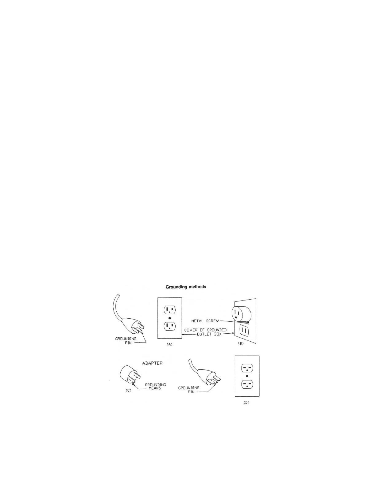
Grounding Instructions
Caution: This tool must be grounded while in use to protect the operator from electric shock.
In the event of a malfunction or breakdown, grounding provides a path of least resistance for electric
current to reduce the risk of electric shock. This tool is equipped with an electric cord having an
equipment-gr ounding conduct or and a grounding pl ug. The plug m ust be plugged into a mat ching outl et
that is properly installed and grounded in acc or danc e with all local codes and ordinances.
Do not modify the plug provided. If it will not fit the outlet, have the proper outlet installed by a qualified
electrician.
Improper connection of the equipment-grounding conductor can result in a risk of electric shock. The
conductor, with insulation having an outer surface that is green with or without yellow stripes, is the
equipment-gr ounding c onductor . If r epair or repl acement of the elec tri c cord or pl ug is necessary , do not
connect the equipment-grounding conductor to a live terminal.
Check with a qualified electrician or service personnel if the grounding instructions are not completely
understood, or if in doubt as to whether the tool is properly grounded. Use only three wire extension
cords that hav e three- pr ong gr ounding plugs and three-pole r ec eptacles that accept the tool’s plug.
Repair or replace a dam aged or worn cord im mediately.
This tool is int ended for use on a circuit that has an outl et that looks like the one illustr ated in sketch A.
The tool has a groundi ng that looks li ke the pl ug ill ustrated i n sketch A. A temporary adapter, which looks
like the adapter illustrat ed in sketches B and C, may be used to connect this plug to a 2-pole receptacle
as show in sketch B if a properly until a properly grounded outlet can be installed by a qualified
electrici an. (This adapter is not permitted in Canada) The green-color ed rigid ear, lug, the like, extendi ng
from the adapter must be c onnec ted to a permanent ground such as a properly gr ounded outlet box.
This tool is int ended for use on a circuit that has an outlet that l ooks like the one illustrated in sketch D.
The tool has a grounding t hat looks like the plug illustrated in sketch D. Make sure the tool is connected to
an outlet havi ng the same configuration as the pl ug. No adapter is available or should be used wit h this
tool. If the tool must be reconnected for use on a different type of electric circuit, the reconnect ion should
be made by qualified service personnel; and after reconnection, the tool should comply with all local
codes and ordinances.
6
Page 7
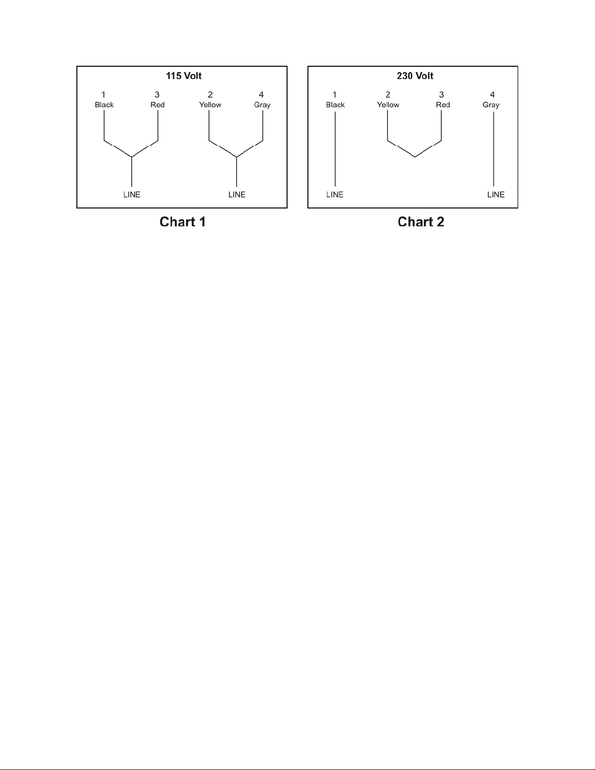
The conversion fro m 115V to 230V op erat ion must be done by a qualified elect rician.
Specifications
Model Number .......................................................................................................................... HVBS-56M
Stock Number................................................................................................................................ 414458
Horizontal Capacity:
Round @ 90° .................................................................................................................................... 5”
Round @ 45° .................................................................................................................................... 3”
Rectangle @ 90° .......................................................................... 5”(H) x 5-3/4”(W), and 2”(H) x 6”(W)
Rectangle @ 45° ....................................................................................................... 4-1/2”(H ) x 3”(W)
Throat Depth .......................................................................................................................................... 5”
Vertical Work Table Size...................................................................................................... 9-5/8” x 9-1/2”
Vise Swivels ......................................................................................................................................... 45°
Blade Size ............................................................................................................... 1/2” x 0.025” x 64-1/2”
Blade Wheel Diameter ...................................................................................................................... 7-3/8”
Speeds ........................................................................................................................ 80, 120, 200 SFPM
Bed Height ..................................................................................................................................... 25-1/2 ”
Floor Space Requi r ed ...................................................................................................... 16-1/4 ” x 42-1/2”
Motor (UL listed) ........................................................................... 1/2 HP, 1 Ph, 115/230V, prewired 115V
Net Weight (approx.)...................................................................................................................... 115 lbs.
The specifi cati ons in this m anual are giv en as general i nform ation and are not bi nding. J ET reserv es the
right to eff ect, at any tim e and wit hout pri or notic e, changes or alt erat ions to par ts, fi tti ngs, and accessory
equipment deemed nec essary for any reason whatsoever.
7
Page 8
Unpacking and Clean-Up
Note: Read and understand the entire manual
before attem pting setup or operation.
1. Remove all content s form the shipping
carton.
2. I nspect c ontents for shippi ng dam age and
report any damage t o your distributor.
3. Wipe bed and vise assembly wit h cl ean
cloth to remov e excess oil used to pr event
rust.
4. Do not discard any packing material until
saw has been assembl ed and is running
properly.
Tools Supplied for Assembly
Wrench 12/14mm
4mm Angle Hex Wrench
Tools Required for Assembly
• #2 Cross Point Screwdriver
• 6-8" Adjustable Wrench or Wrench Set
• Pliers - Regular or Needl e Nose
• Ratchet and Sockets will Speed Assembly
Assembly
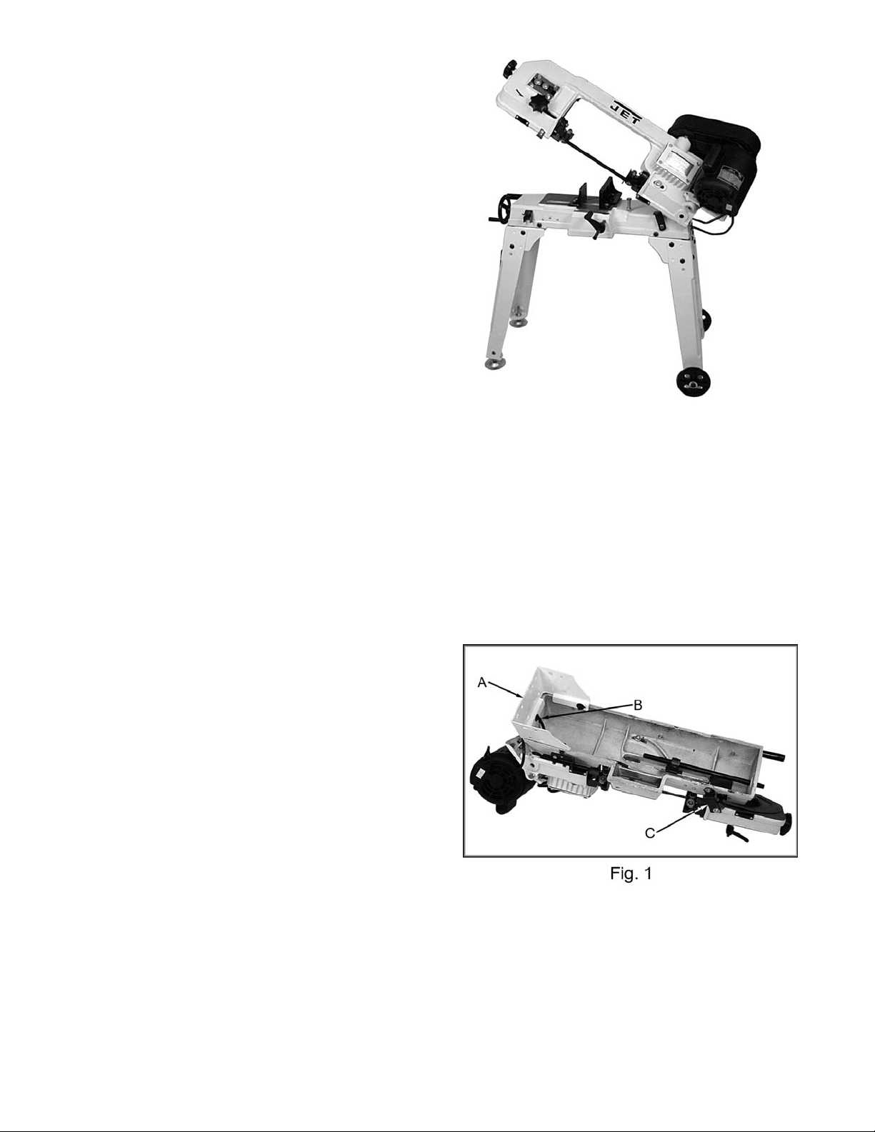
1. With the help of another person tur n the saw
over so that it rests on the m otor and saw
bow, Figure 1. Place it on a piece of
cardboard, or a surface that will not damage
the saw.
2. Attach a cross brace (A, Fig. 1) to t he motor
side of the bed using t hr ee 5/16”x 1” hex cap
bolts, six 5/16” flat washers, and secure with
three 5/16” hex nuts. Hint: Tighten the nut
(B, Fig. 1) on the end of the bed first
followed by the nuts on the si des.
3. Attach a leg to the cross brace using f our
5/16”x3/ 4” car ri age bolts, four 5/16” flat
washers and four 5/ 16” hex nuts. Use a
12mm wrench to tighten. Repeat for other
leg.
4. Remove the brace (C, Fig. 1) on the
opposite end of the bed and bow using a
10mm wrench.
8
Page 9

5. Attach a cross brace to the opposit e end of
the bed using three 5/ 16”x1” hex cap bolts,
six 5/16” flat washers, and secur e wi th three
5/16” hex nuts. Tighten the nut on the end
of the bed first followed by the nuts on the
sides.
6. Attach a leg to the cross brace using f our
5/16”x3/ 4” car ri age bolts, four 5/16” flat
washers and four 5/ 16” hex nuts. Use a
12mm wrench to tighten. Repeat for other
leg.
7. Attach the adjustable feet (A, Fig. 2) to the
legs opposite of t he m otor, using the
provided hardware.
8. Slide the axle (A, Fig. 3) thr ough the legs.
Place a large fl at washer (B, Fi g. 3) on both
sides of the wheels and plac e on the axle.
Secure wheels with t wo spli t pins (C, Fig. 3).
9. Carefully tur n the saw onto it s stand and
adjust the feet so the bed is level.
10. P ut the handle (A, Fig. 4) through holes in
the stand legs opposite of the wheel
assembly and secure with split pins.
9
Page 10

11. S lide pulley cov er (A, Fi g. 5) around motor
shaft and worm gear shaf t. Secure with two
hex cap screws and washers (B, Fig. 5).
12. Lift motor with one hand while the other
hand places V-belt (C, Fig.5) on both pulleys.
13. A ttach the tension brac k et (D , Fi g. 5) to the
saw bow with one 5/16”x3/4” hex head bolt
and flat washer (E, Fig. 5).
14. Connec t the two tension brack ets with one
5/16”x3/ 4” car ri age bolt, one 5/16” flat
washers and one 5/16” hex nut (F, Fig. 5).
Hint: Insert the carri age bolt from the inside
so the hex nut is easy to access with a
wrench.
15. Tension belt by pressing down on the m otor
while tightening hex nut (F, Fig. 5) until
finger pressure on the belt between the two
pulleys causes approxim ately 1/2" deflecti on.
Close pulley cover . Don’t ov er tighten the
belt.
16. Insert stop rod (A, Fig. 6) into bed and
tighten set screw (B, Fig. 6). Slide stock
stop (C, Fig. 6) onto r od and tight en set
screw (D, Fig. 6) to hold in plac e.
17. S lide handwheel (E, Fi g. 6) onto shaft and
secure by tight ening set screw (F, Fig. 6).
Make sure set screw seats on flat portion of
shaft.
Vertical Cutting Plate Assembly
Note: These steps are only nec essary when
using the bandsaw in the ver tical mode.
Disconnect the b and saw
from the power source before making any
repairs or adjustments. Failure to comply
may cause serious injury!
1. Disconnect the b and saw from the power
source.
2. Raise the arm to the vertical position and
lock in place wit h lev er (A, Fi g. 7) .
3. Loosen bolt (B, Fig. 7) and insert br acket (C,
Fig. 7). Tighten bolt just enough to hold the
bracket in place.
10
Page 11

4. Remove two screws (D, Fig. 7) and plate ( E,
Fig. 7).
5. G uide blade through slot i n table (A, Fig. 8)
and fasten table with two screws (B, Fig. 8).
6. F asten support bracket to under si de of table
using screw (C, Fig. 8) and hex nut .
7. T ighten bolt (B, Fig 7).
Electrical Connections
All electrical connect ions
must be completed by a qualified electrician.
Failure to compl y may cause seri ou s in ju ry!
The HVBS-56M band saw is rated at 115/230V
and comes from the fact or y prewir ed 115V .
To switch to 230V operation, follow the wiri ng
diagram found on the inside of the motor
junction box. The pl ug on the end will have to
be replaced with a plug that is rated at 230V.
This bandsaw is designed f or use on a circ uit
with an outlet t hat looks li k e ( A, Fig. 9). The
bandsaw has a grounding prong as i llustrated in
(B, Fig. 9). A temporary adapt er (C, Fig. 9) may
be used to connect the plug t o a two pole
receptacl e ( D, Fi g. 9) if a properly grounded
outlet is not av ailable. The temporary adapter
should only be used until a pr operl y gr ounded
outlet can be instal led by a qualified electrician.
The green color ed lug m ust be securely
fastened to the cov er plate screw.
Before hooki ng up to t he power source, be sure
the switch is in the off posi tion.
11
Page 12

Changing Blade Speed
1. Disconnect the mach in e f rom the power
source.
2. Place saw arm in the horizontal position.
3. Loosen tensioning pl ate hex nut (A, Fig.10).
4. O pen pulley cover (B, Fig. 10). Lift mot or
with one hand while pl aci ng the belt (C, Fig.
10) on the desired pull ey c om bination.
5. T ensi on belt by pressing down on the motor
while tightening hex nut (A, Fig. 10) until
finger pressure on the belt between the two
pulleys causes approxim ately 1/2" deflecti on.
Close pulley cover . Don’t ov er tighten the
belt.
6. Close pulley cover and connec t t o power
source.
The general rule for band saw blade speed is
the harder the material being cut, the slower the
blade speed. Reference Figure 11 for a guide to
blade speed for a type of material being cut.
Adjusting Blade Guides
1. Disconnect mach in e f rom the power
source.
2. Loosen k nob ( A , Fig. 12) and slide blade
guide assembly ( B, Fig. 12), as close as,
possible without interference to the material
being cut. Tighten knob.
3. Loosen bolt (C, Fig. 12) and slide blade
guide assembly ( D, Fi g. 12), as close as,
possible without interference to the material
being cut. Tighten bolt
Adjusting Blade Tension
1. Disconnect mach in e f rom the power
source.
2. O pen blade cover and observe the posi tion
of the blade on the wheel. If the blade is not
next to the wheel flange, adjust blade
tracki ng following the steps under "Adjusting
Blade Tracking".
3. If the blade is next to the wheel fl ange,
loosen the blade guide assembly lock knob
and hex head bolt (A & C, Fig. 12) and sli de
the blade guide assembl ies as far apart as
possible. Loc k in pl ac e.
4. Depres s bl ade. Finger pressure should
cause approxim ately .004" deflection. T ur n
blade tension knob ( B , Fi g. 12) until the
proper tension i s achieved. Re-position
guides for cutting material.
12
Page 13

Changing Blades
1. Disconnect mach in e f rom the power
source.
2. Raise the saw arm to the vertical position
and lock in place wit h loc k lever.
3. O pen blade cover by removing the small
knob found on the topsi de of t he bow.
4. Remove red blade guards by removing two
screws.
It is essential these two
guards be installed after the new blade has
been fitted. Fai lu re to comply may cause
serious injury!
5. Release tension on the blade by turning
tensioning knob ( B , Fi g. 12), and remove the
blade.
6. Place new blade between the blade guide
assemblies and around each wheel. Make
sure blade teeth are pointing in the proper
direction, Figure 13. Tension enough to
hold in place.
7. I nstall red blade guards with two screws.
8. T ensi on blade fully, see “Adjusting Blade
Tension”.
9. Place two to three drops of li ghtweight oil on
the blade.
10. Connec t machine to the power source.
11. Run sa w and make sure blade is tracking
properly, see "Adjusting Blade Tracki ng".
As a general rule, t he thinner the material to be
cut, the more teeth per inch on the blade. A
minimum of three teeth should be in contact with
the material at all times during the cut. If the
teeth straddl e the material, severe damage can
result to the mat eri al and the blade.
Adjusting Blade Guide Bearings
1. Disconnect mach in e f rom the power
source.
2. Loosen bolt (A, Fig. 14) and adjust assem bly
so that back roll er bearing is
approximat ely .002" - .003" from the back of
the blade. Tight en bolt.
3. Loosen nut (B, Fig. 14) and turn nut (C, Fig.
14) to adjust ecc entric bearing to a
clearance of .001" . Tighten nut (B, Fig. 14)
to lock.
4. Connect machine to power source.
13
Page 14

Adjusting Blade Tracking
Blade tracking adjustment
requires runni ng the saw with th e back co ver
open. This adjustment must be completed by
qualified persons only. Failure to comply
may cause serious injury!
Blade tracking has been set at the factory and
should not need imm ediate adjustment. If blade
tracki ng should ever require adjustment:
1. Conf irm that blade tensi on is set proper ly.
To adjust, see section titled "Adjusting Bl ade
Tension".
2. Mak e sure the saw is in its slowest speed,
see “Changing Blade Speeds”.
3. Move saw arm to the vertical posi tion and
lock in place with the lock lever.
4. Conf irm that blade tensi on is set proper ly.
To adjust, see section titled " Adjusting
Blade Tension" .
5. O pen blade cover by removing the knob
found on the top side of t he bow.
6. Run saw and observe blade. Blade should
run next to but not tightl y against wheel
flange.
7. Loosen bolts (A, Fig. 15).
8. T ur n set scr ew (B, Fig. 15) while observing
blade tracki ng on wheel. Turn set screw
clockwise to t r ack closer t o wheel flange.
Turn set screw counter-clockwise to track
away from the wheel flange. Hint: start
with ¼ turns on the set screw. The tracking
is sensitive.
9. O nc e tracking is set, tight en bolts (A, Fig.
15).
Adjusting Feed Pressure
1. T ur n handle (A, Fig. 16) clockwise to
decrease cutti ng pr essure and counter clockwise to incr ease cut ting pressure.
A good indication of proper feed pressure is the
color and shape of the c utti ng c hips. If the chips
are thin or powdered, increase the f eed pr essure.
If the chips are burned and heav y , decr ease the
feed pressure. If they are still burned and heav y,
reduce the blade speed. Optimum feed
pressure has been set when the chips are curled,
silvery, and warm .
14
Page 15

Blade-Table Squareness
1. The band saw blade must be perpendicul ar
to the table to ensure a straight cut. This
setting should be checked. Special blade
setting gauges can be purchased for this
type of inspection; however, it can also be
done using more common shop items, as
follows.
2. First “extend” the surface of the blade by
clamping a straight , flat object to the blade.
(Figure 16a uses a small, lightweight
aluminum ruler.) Use a lightweight clamp.
3. Place a square on the table and against the
ruler. The square should l ie flat against the
ruler without a gap.
4. If there i s a gap, loosen the bolt (Figure 16b)
on each blade guide assembly and rotate
the blade guide assembly until there is no
more gap between the square and the r uler.
5. Re-tighten the bolts.
3. Adjust the blade guides so they are as close
as possible t o the material without int erfer ing.
4. T her e is a scale on the back side of the bed
to aid in setting up the vise for 90° cuts or a
particular miter. Hint: Always check the
vise setup with a combination square,
against the bl ade and v ise, so that you can
verify the vise setting is correct.
6. After making this adjustment, be sure to recheck other blade adjustments as noted in
your manual.
Adjusting Automatic Shut-Off
The saw should stop aft er the cut has been
completed:
• If the saw complet es the c ut and continues
to run, adjust the stop tip (A, Fig. 17) down.
• If the saw shuts off bef or e the cut is
complete, adjust the stop tip (A, Fig. 17) up.
• If the saw stops cutting but continues to run,
adjust the stop bol t (B , fi g. 17) down.
The saw is properly adjusted when the saw
shuts off just after the blade has finished the cut.
Adjusting the Vise
1. T o open and c lose the vise use the
handwheel (C, Fi g. 17).
2. T he v ise can be adjusted for square and
miter cuts. Loosen the hex c ap bolts and
adjust the vise for the cut.
Fig. 16a
Fig. 16b
15
Page 16

Lubrication
Ball bearings on t he blade guide assemblies and
the blade wheels are permanently sealed and
require no lubrication.
Lubricate the vise lead screw as needed with #2
tube grease.
Gear box oil will hav e to be changed aft er 90
days of operation. Thereafter, change ever y six
months.
To change the gear box oil:
1. Disconnect mach in e f rom the power
source.
2. Place saw arm in the horizontal position.
3. Remove screws (A, Fig. 18) fr om the gear
box and remove cover plate and gasket.
4. Hold a container under t he lower right corner
of the gear box with one hand whil e sl owly
raising the saw arm with the other. Drain
completely.
5. Place arm in the horizont al posi tion. Wipe
out remaining oil with a rag.
6. F ill gear box with approximately 1/2 pint of
MOBIL SHC 634.
7. Replace gasket and cov er. Fasten cov er
with bolts.
16
Page 17

Breakdown for Bow Assembly
17
Page 18

Breakdown for Base Assembly
18
Page 19

Parts List for the HVBS-56M Bandsaw
Index Part
No. No. Description Size Qty.
1 .......... TS-0051031 .............................. Hex Cap Bolt ..........................................5/16”x3/4” ................... 4
2 .......... TS-0561011 .............................. Hex Nut..................................................1/4”............................. 1
3 .......... TS-0680021 .............................. Flat Washer ...........................................1/4”............................. 4
4 .......... HVBS56M-04 ............................ Stand Leg ................................................................................. 4
4-1....... HVBS56 M-04-1 ......................... Cross Brace .............................................................................. 2
5 .......... HVBS56M-05 ............................ Washer ..................................................................................... 6
6 .......... HVBS462-006 ........................... Cotter Pin ...............................................1/8”x1” ........................ 4
7 .......... HVBS56M-07 ............................ Axle .......................................................................................... 1
8 .......... TS-0680031 .............................. Flat Washer ...........................................5/16” ......................... 38
9 .......... HVBS56M-09 ............................ Wheel ....................................................................................... 2
10 ........ HVBS56M-010 .......................... Washer ..................................................1/4 ”x5/8” ..................... 1
11 ........ TS-0051051 .............................. Hex Cap Bolt ..........................................5/16”x1” ...................... 4
11-1 ..... HVBS56M-11-1 ......................... Ca rriage Bolt ..........................................5/16”x3/4” ................. 16
11-2 ..... TS-0051051 .............................. Hex Cap Bolt ..........................................5/16”x1” ...................... 6
12 ........ TS-0561021 .............................. Hex Nut..................................................5/1 6” ......................... 22
13 ........ HVBS56M-013 .......................... Adjustab le Foot ......................................................................... 2
14 ........ HVBS462-014 ........................... Floor Stand Handle ................................................................... 1
15 ........ HVBS462-015 ........................... Adjusting Rod ........................................................................... 1
16 ........ HVBS462-016 ........................... Electric Cord ............................................................................. 1
17 ........ HVBS462-017 ........................... Pivoting Rod ............................................................................. 1
18 ........ HVBS462-018 ........................... Support P late ............................................................................ 1
19 ........ HVBS462-019 ........................... Stock Stop ................................................................................ 1
20 ........ TS-0270021 .............................. Socket Set Screw ...................................5/16”x5/16” ................. 4
21 ........ HVBS
22 ........ HVBS462-022 ........................... Wire Relief Retainer .................................................................. 2
25 ........ TS-0051031 .............................. Hex Cap Bolt ..........................................5/16”x3/4” ................... 1
27 ........ HVBS462-027 ........................... Wheel Handle ........................................................................... 1
28 ........ HVBS462-028 ........................... Hand Wheel .............................................................................. 1
29 ........ HVBS56M-029 .......................... Toggle Switch Assem bly ........................................................... 1
29-1 ..... HVBS56M-029-1 ....................... Plastic Cover ............................................................................. 1
30 ........ HVBS462-030 ........................... E-Ring ...................................................E10 ............................ 1
31 ........ HVBS462-031 ........................... Screw ....................................................5/16”x1” ...................... 3
32 ........ HVBS462-032 ........................... Lead Screw ............................................................................... 1
33 ........ HVBS462-033 ........................... Vise Nut .................................................................................... 1
34 ........ HVBS462-034 ........................... Moveable Vise Plate ................................................................. 1
35 ........ TS-0680041 .............................. Flat Washer ...........................................3/8”x1” ........................ 4
36 ........ TS-0090061 .............................. Hex Cap Bolt ..........................................3/8”x1-1/4” .................. 1
37 ........ HVBS462-037 ........................... Bed ........................................................................................... 1
38 ........ HVBS462-038 ........................... Cross Round Head Screw ......................3/16”x3/8” ................... 2
39 ........ HVBS462-039 ........................... Scale ........................................................................................ 1
40 ........ HVBS462-040 ........................... Electric Cord Clip ...................................................................... 1
42 ........ HVBS56M-042 .......................... Screw ....................................................M4x16 ........................ 2
43 ........ HVBS462-043 ........................... Rubber Ring.............................................................................. 1
44 ........ HVBS462-044 ........................... Electric Cable ............................................................................ 1
45 ........ HVBS462-045 ........................... Nut Plate ................................................................................... 1
45-1 ..... HVBS56M-045-1 ....................... Spring Handle Bracket .............................................................. 1
46 ........ HVBS462-046 ........................... Spring Adjusting Screw ............................................................. 1
47 ........ HVBS462-047 ........................... Spring ....................................................................................... 1
48 ........ HVBS462-048 ........................... Cross Round Head Screw ......................3/16”x3/8” ................... 4
49 ........ HVBS462-049 ........................... Mitering Vise Plate .................................................................... 1
50 ........ TS-0081031 .............................. Hex Cap Bolt ..........................................5/16”x3/4” ................... 6
462-021 ........................... Stock Stop Rod ......................................................................... 1
19
Page 20

Index Part
No. No. Description Size Qty.
49 ........ HVBS462-049 ........................... Mitering Vise Plate .................................................................... 1
50 ........ TS-0081031 .............................. Hex Cap Bolt ..........................................5/16”x3/4” ................... 6
51 ........ TS-0680031 .............................. Flat Washer ...........................................5/16” ........................... 3
52 ........ TS-0081071 .............................. Hex Cap Bolt ..........................................5/16”x1-1/2” ................ 1
53 ........ TS-0091071 .............................. Hex Cap Screw ......................................7/16”x2” ...................... 1
54 ........ HVBS56M-054 .......................... Pivot Bracket ............................................................................. 1
55 ........ HVBS462-055 ........................... Vertical Cutting Plate ................................................................. 1
56 ........ HVBS462-056 ........................... Stand for Vertical Cutting Plate.................................................. 1
57 ........ HVBS56M-057 .......................... Adjustable Bracket LH ............................................................... 1
57A ..... HVBS56M-057A........................ Adjustable Bracket Assembly LH ............................................... 1
58 ........ HVBS462-058 ........................... Knob ......................................................1/4”............................. 1
59 ........ HVBS56M-380 .......................... Blade Back Safety Cover .......................................................... 1
60 ........ HVBS462-060 ........................... C-C lip ....................................................S1 0 ............................ 4
61 ........ BB-6000ZZ ............................... Ball Bearing ...........................................6000ZZ....................... 6
62 ........ HVBS462-062 ........................... Guide Pivot ............................................................................... 2
62A ..... HVBS462-062A......................... Center Shaft Assembly (Includes: #60-62) ................................. 1
62-1 ..... HVBS462-062-1 ........................ Centrifugal Guide Pivot ............................................................. 2
62-1A .. HVBS462-062-1A ..................... Eccentric Shaft Assembly (Includes: #60,61,62-1) ..................... 1
63 ........ HVBS462-063 ........................... Bearing Shaft Pin ...................................................................... 2
64-1 ..... HVBS462-064-1 ........................ Blade S eat Lef t ......................................................................... 1
64-2 ..... HVBS462-064-2 ........................ Blade S eat Right ....................................................................... 1
65 ........ HVBS56M-065 .......................... Adjustab le Bracket-RH .............................................................. 1
65A ..... HVBS56M-065A........................ Adjustable Bracket-Assembly RH .............................................. 1
66 ........ HVBS56M-066 .......................... Lock Knob ................................................................................. 1
67 ........ TS-0720081 .............................. Lock Washe r ..........................................5/16 ” ........................... 3
68 ........ TS-0813051 .............................. Flat Head Machine Screw ......................1/4 ”X3/4 ” .................... 3
69 ........ HVBS462-069 ........................... Bearing Guard .......................................................................... 1
70 ........ TS-0561031 .............................. Hex Nut..................................................3/8 ”............................. 4
71 ........ HVBS462-071 ........................... Blade Wheel Drive .................................................................... 1
72 ........ HVBS462-072 ........................... Bearing Cover ........................................................................... 2
73 ........ HVBS462-073 ........................... Key ........................................................5x5x25 ....................... 2
74 ........ HVBS56M-060 .......................... C-C lip ....................................................S1 5 ............................ 1
75 ........ HVBS462-075 ........................... Hex Cap Bolt (w/Washer) .......................1/4”x1/2” ..................... 8
76 ........ HVBS462-076 ........................... Switch Cut Off Trip .................................................................... 1
77 ........ HVBS462-077 ........................... Idle Blade Wheel ....................................................................... 1
78 ........ TS-0680031 .............................. Flat Washer ...........................................5/16” ........................... 2
79 ........ HVBS462-079 ........................... Blade T ension Knob ...............................3/8”............................. 1
80 ........ HVBS462-080 ........................... Spring ....................................................................................... 1
81 ........ HVBS56M-081 .......................... Saw Bow................................................................................... 1
82 ........ HVBS56M-082 .......................... Washer ..................................................................................... 1
83 ........ TS-0070031 .............................. Cap Screw .............................................1 /2”x1-1/2” .................. 2
84 ........ HVBS56M-084 .......................... Motor Mount Plate ..................................................................... 1
84-1 ..... HVBS56M-084-1 ....................... Tension Bracket ........................................................................ 1
85 ........ HVBS463-085 ........................... Motor .....................................................1/2 HP, 1Ph ................ 1
............ HVBS463-085-01 ...................... Capacitor Cover (not shown) ..................................................... 1
............ HVBS462-085-02 ...................... Capacitor (not shown) ............................................................... 1
86 ........ HVBS462-086 ........................... Motor Pulle y .............................................................................. 1
87 ........ BB-6202ZZ
88 ........ HVBS462-088 ........................... Bearing Bushing........................................................................ 1
89 ........ OS-15375 ................................. Oil Seal ..................................................................................... 2
90 ........ HVBS462-090 ........................... Transmiss ion Wheel Sha ft......................................................... 1
91 ........ HVBS462-091 ........................... Worm Gear ............................................................................... 1
92 ........ HVBS462-092 ........................... Gear Box Gasket ...................................................................... 1
93 ........ HVBS462-093 ........................... Gear Box Cover ........................................................................ 1
............................... Ball Bearing ...........................................6202ZZ....................... 6
20
Page 21

Index Part
No. No. Description Size Qty.
94 ........ HVBS462-094 ........................... Worm Gear (w/Sha ft) ................................................................ 1
95 ........ HVBS462-095 ........................... Spring Pin ................................................................................. 1
96 ........ HVBS462-096 ........................... Bearing Bushing........................................................................ 1
97 ........ TS-0050011 .............................. Hex Cap Bolt ..........................................1/4”x1/2” ..................... 3
98 ........ HVBS56M-098 .......................... Clamp ....................................................................................... 2
99 ........ HVBS462-099 ........................... Spacer ...................................................................................... 1
100 ...... HVBS462-100 ........................... Flat Cross Head Screw ..........................5/32”x3/8” ................... 8
101 ...... HVBS462-101 ........................... Worm Gear Pulle y ..................................................................... 1
102 ...... TS-0720081 .............................. Lock Washe r ..........................................5/16” ........................... 2
103 ...... HVBS462-103 ........................... Blade Tension Sli ding Plate ....................................................... 1
104 ...... TS-0270051 .............................. Socket Set Screw ...................................5/16”x1/2” ................... 3
105 ...... HVBS462-105 ........................... Spring Pin ................................................................................. 1
106 ...... HVBS462-106 ........................... Sliding Plate Draw Block ........................................................... 1
107 ...... HVBS462-107 ........................... Blade Wheel Shaft .................................................................... 1
108 ...... HVBS462-108 ........................... Shaft Block ............................................................................... 1
109 ...... HVBS462-109 ........................... Blade Tension Sli ding Guide ..................................................... 2
110 ...... HVBS462-110 ........................... Motor Pul l ey Cover Assembly.................................................... 1
111 ...... TS-0680031 .............................. Flat Washer ...........................................5/16” ........................... 1
112 ...... VB-A22 ..................................... V-Bel t .....................................................A22 ............................ 1
113 ...... 414301 ..................................... Blade ........................................................................................ 1
114 ...... TS-0680041 .............................. Flat Washer ...........................................3/8”............................. 4
115 ...... TS-0561011 .............................. Hex Nut..................................................1 /4”............................. 1
116 ...... HVBS
117 ...... HVBS463-171 ........................... Hex Screw .............................................3/8”x1-1/4” .................. 1
120 ...... HVBS462-120 ........................... Bushing .................................................................................... 1
122 ...... TS-0561041 .............................. Hex Nut..................................................7 /16” ........................... 1
123 ...... TS-0050031 .............................. Cap Screw .............................................1 /4”x3/4” ..................... 1
124 ...... HVBS463-124 ........................... Machine Screw ......................................3/16”x3/4” ................... 2
126 ...... HVBS462-126 ........................... Bushing .................................................................................... 1
132 ...... HVBS462-132 ........................... Blade Guard- Right .................................................................... 1
132-1 ... HVBS462-132A......................... Blade Guard- Left ....................................................................... 1
156 ...... HVBS462-156 ........................... Round Head Screw ................................3/16”x3/4” ................... 1
157 ...... HVBS462-157 ........................... Star Washer ...........................................3/16” ........................... 3
158 ...... HVBS463-158 ........................... Hex Nut ..................................................3/16” ........................... 2
159 ...... HVBS463-159 ........................... Round Cross Head Scre w ......................3/16”x1/2” ................... 1
............ HVBS56M-BS ........................... Blade Speed Label (not shown) ................................................. 1
............ HVBS56M-ID ............................ I.D. Label (not shown) ............................................................... 1
............ HVBS56M-WL .......................... Warning Label (not shown)........................................................ 1
............ JM-56M..................................... Stripe Decal (not shown) ........................................................... 1
463-170 ........................... Wire Plug .................................................................................. 3
21
Page 22

Wiring Diagram
22
Page 23

Notes
23
Page 24

427 New Sanford Road
LaVergne, Tennessee 37086
Phone: 800-274-6848
www.jettools.com
24
 Loading...