

Page 1
This .pdf document is bookmarked
Operating Instructions and Parts Manual
15-inch Variable Speed Drill Press
Models: J-A3816, J-A5816, J- A5818
Model J-A3816 Model J-A5816
JET
427 New Sanford Road Part No. M-354500
LaVergne, Tennessee 37086 Revision E 03/2015
Ph.: 800-274-6848 (ECR TW0135)
www.jettools.com Copyright © 2015 JET
Page 2

Warranty and Service
JET warrants every product it sells against manufacturers’ defects. If one of our tools needs service or repair, please contact
Technical Service by calling 1-800-274-6846, 8AM to 5PM CST, Monday through Friday.
Warranty Period
The general warranty lasts for the time period specified in the literature included with your product or on the official JET
branded website.
• JET products carry a limited warranty which varies in duration based upon the product. (See chart below)
• Accessories carry a limited warranty of one year from the date of receipt.
• Consumable items are defined as expendable parts or accessories expected to become inoperable within a
reasonable amount of use and are covered by a 90 day limited warranty against manufacturer’s defects.
Who is Covered
This warranty covers only the initial purchaser of the product from the date of delivery.
What is Co vered
This warranty covers any defects in workmanship or materials subject to the limitations stated below. This warranty does not
cover failures due directly or indirectly to misuse, abuse, negligence or accidents, normal wear-and-tear, improper repair,
alterations or lack of maintenance. JET woodworking machinery is designed to be used with Wood. Use of these machines in
the processi ng of m et al, plastics, o r other m aterials o utside recommended gu idelines m ay voi d the warranty. Th e exceptio ns
are acrylics and other natural items that are made specifically for wood turning.
Warranty Limitations
Woodworking products with a Five Year Warranty that are used for commercial or industrial purposes default to a Two Year
Warranty. Please contact Technical Service at 1-800-274-6846 for further clarification.
How to Get Technical Support
Please contact Technical Service by calling 1-800-274-6846. Please note that you will be asked to provide proof of ini tial
purchase when calling. If a product requir es further inspection, th e Technic a l Service representativ e will expl ain and assist
with any additional action needed. JET has Authorized Service Centers located throughout the United States. For the name of
an Authorized Service Center in your area call 1-800-274-6846 or use the Service Center Locator on the JET website.
More Informa t io n
JET is constantly adding new products. For complete, up-to-date product information, check with your local distributor or visit
the JET website.
How State Law Appli es
This warranty gives you specific legal rights, subject to applicable state law.
Limitations on This Warranty
JET LIMITS ALL IMPLIED WARRANTIES TO THE PERIOD OF THE LIMITED WARRANTY FOR EACH PRODUCT.
EXCEPT AS STATED HEREIN, ANY IMPLIED WARRANTIES OF MERCHANTABILITY AND FITNESS FOR A PARTICULAR
PURPOSE ARE EXCLUDED. SOME STATES DO NOT ALLOW LIMITATIONS ON HOW LONG AN IMPLIED WARRANTY
LASTS, SO THE ABOVE LIMITATION MAY NOT APPLY TO YOU.
JET SHALL IN NO EVENT BE LIABLE FOR DEATH, INJURIES TO PERSONS OR PROPERTY, OR FOR INCIDENTAL,
CONTINGENT, SPECIAL, OR CONSEQUENTIAL DAMAGES ARISING FROM THE USE OF OUR PRODUCTS. SOME
STATES DO NOT ALLOW THE EXCLUSION OR LIMITATION OF INCIDENTAL OR CONSEQUENTIAL DAMAGES, SO THE
ABOVE LIMITATION OR EXCLUSION MAY NOT APPLY TO YOU.
JET sells through distributors only. The specifications listed in JET printed materials and on official JET website are given as
general information and are not binding. JET reserves the right to effect at any time, without prior notice, those alterations to
parts, fittings, and accessory equipment which they may deem necessary for any reason whatsoever. JET
are not sold in Canada by JPW Industries, Inc.
Product Listing with Warranty Period
90 Days – Parts; Consumable items; Light-Duty Air Tools
1 Year – Motors; Machine Accessories; Heavy-Duty Air Tools; Pro-Duty Air Tools
2 Year – Metalworking Machinery; Electric Hoists, Electric Hoist Accessories; Woodworking Machinery used
for industrial or commercial purposes
5 Year – Woodworking Machinery
Limited Lifetime – JET Parallel clamps; VOLT Series Electric Hoists; Manual Hoists; Manual Hoist
Accessories; Shop Tools; Warehouse & Dock products; Hand Tools
NOTE: JET is a division of JPW Industries, Inc. References in this document to JET also apply to JPW Industries, Inc., or any
of its successors in interest to the JET brand .
®
branded products
2
Page 3

Table of Contents
Warranty and Servic e .......................................................................................................................................... 2
Table of Contents ................................................................................................................................................ 3
Warnings ............................................................................................................................................................. 4
Safety Instruction s for Dril l Pr e sses .................................................................................................................. 6
ON/OFF Switch Padlock ................................................................................................................................... 6
Specifica tio ns ...................................................................................................................................................... 7
Introduction .......................................................................................................................................................... 8
Set-up and Assembl y ........................................................................................................................................... 8
Securing the Base ............................................................................................................................................ 8
Assembly ......................................................................................................................................................... 8
Cleaning .............................................................................................................................................................. 9
Electri c al Connec tion ........................................................................................................................................... 9
Operating Contr ols ............................................................................................................................................... 9
ON/OFF Switch ................................................................................................................................................ 9
Speed Control Handwheel ................................................................................................................................ 9
Depth Stop ..................................................................................................................................................... 10
Operating P re c a u tions .................................................................................................................................... 10
Drilling Recommendations ................................................................................................................................. 10
Maintenance ...................................................................................................................................................... 11
Replacement of Drive Belt .............................................................................................................................. 11
Replacement of Motor .................................................................................................................................... 11
Lubrication ......................................................................................................................................................... 11
Adjustments ....................................................................................................................................................... 12
Table Adjustment ........................................................................................................................................... 12
Wiring Diagrams ................................................................................................................................................ 12
Electrical ............................................................................................................................................................ 1 3
115 Volt Operati on ......................................................................................................................................... 13
230 Volt Operati on ......................................................................................................................................... 13
Permanentl y Connect ed Tools ........................................................................................................................ 13
Grounding Inst r uc tions ................................................................................................................................... 14
Extension Cords ............................................................................................................................................. 14
Troubleshooting ................................................................................................................................................. 15
Parts .................................................................................................................................................................. 15
Exploded View — Head Model s J-A 5816 and J - A 5818 ................................................................................... 16
Parts List - Head Models J-A 5816 and J - A 5818 .............................................................................................. 17
Exploded View — Head Model J-A3816 ......................................................................................................... 19
Parts List - Head Model J -A3816 .................................................................................................................... 2 0
Exploded View – Base Floor M odels J-A 3816, J-A5816 and J-A5818 ............................................................. 22
Parts List – Base Floor M odels J-A3816, J-A5816 and J-A5818 ...................................................................... 23
Exploded View – Safet y Shi eld A ssembly, Models J-A3816, J-A5816 and J-A 5818 ........................................ 24
Parts List – Safety Shield Assembly (All Models) ............................................................................................ 24
The specifi cati ons in thi s m anual ar e given as general i nform ati on and are not bi ndi ng. J ET r eserv es the r ight to
effect, at any time and without pri or notice, changes or alterations to parts, fittings, and accessory equipment
deemed necessary f or any reason whatsoever.
3
Page 4

Warnings
1. Read and understand the ent ire owner's manual befor e att em pting assembly or operation.
2. Read and understand warni ngs posted on the m ac hine and in t hi s manual. F ailur e to comply wit h all of these
warnings may cause seriou s i njury.
3. Replace warning l abels if they become obscured or removed.
4. This drill press is designed and intended f or use by proper ly trained and ex perienced personnel onl y. If you
are not familiar with the proper and safe operation of a drill press, do not use until proper training and
knowledge have been obtained.
5. Do not use this drill press for other than its intended use. If used for other purposes, J E T disclaims any real or
implied warrant y and holds itself harmless from any injury t hat may result from that use.
6. Keep guards in place and in working order when the mac hine is in use. If removed for maintenance purposes,
use extreme caution and replace the guards immediately.
7. Remove adjust ing keys and wrenches. Form habit of checki ng to see that keys and adjusti ng wrenches are
removed from tool before turning it on.
8. Keep work area clean. Cluttered areas and benches invite accidents.
9. Do not use in dangerous environment. Don't use power tools in damp or wet locati ons, or expose them to
rain. Keep work area well lighted.
10. Keep c hildren away. All visitors should be k ept safe distance from work area.
11. Mak e workshop k id proof with padlock s, m aster switc hes, or by r em ov ing starter keys.
12. Don't force tool. It will do the job bett er and safer at the rate for which it was designed.
13. Use the right tool. Don’t force a tool or attac hm ent to do a job for which it was not designed. The r ight tool will
do the job better and m or e safely at t he rate for which it was designed.
14. Use proper ext ension cord. Mak e sure your ext ension cord is in good condition. When using an ex tension
cord, be sure to use one heavy enough to c arry the current your product will draw. An undersiz ed cord will
cause a drop in li ne volt age result ing in l oss of power and overheat i ng. Tabl e 1 shows the correct size t o use
depending on cord l ength and nam eplate am pere rati ng. If i n doubt, use t he next heav ier gage. The sm aller
the gage number, t he heav ier the cor d.
15. Wear proper appar el. Do not wear loose clothi ng, gloves, neckties, rings, bracel ets, or other jewelry which
may get caught i n moving part s. Nonslip foot wear is recomm ended. Wear prot ective hair cov ering to cont ain
long hair.
16. Alwa ys use saf e ty gl asses. Also use face or dust mask if cutting operat ion is dusty. Everyday eyeglasses only
have impact resistant lenses, they are NOT safety gl asses.
17. Secure work. M ake sure the work pi ece i s securely at tached or cl amped t o the tabl e. Never use your hand t o
hold the work piec e.
18. Don't overreach. Keep proper footing and balance at all times.
19. Maint ain tools with care. Keep tool s sharp and clean for best and safest perf ormance. Foll ow instructi ons for
lubricating and changing accessories.
20. Disconnect tools before servicing; when changing accessories, such as blades, bits, cutter s, and the like.
21. Reduce the risk of unintenti onal star ting. Make sure switch is in off position before plugging in.
22. Use recommended accessories. Consult the owner's manual for recommended accessories. The use of
improper acc essories may cause risk of injury to persons.
23. Never stand on tool. Serious injury could occur if the tool is tipped or if the cutting tool is unintentionally
contacted.
4
Page 5

24. Check f or damaged parts. Before further use of the tool , a guard or other part that is dam aged should be
carefully checked to determine that it will operate properly and perform its intended function - check for
alignment of movi ng parts, binding of mov ing parts, breakage of parts, mounting, and any other conditi ons
that may affect its operation.
25. A guar d or other part that is damaged should be properly repaired or replaced.
26. Do not leave tool running unattended. Turn power off. Don't leave tool until it c om es to a complet e st op.
27. Some dust created by power sanding, sawing, grinding, drilling and other construction activities contain
chemicals known to cause cancer, birth defects or other reproductive harm. Some examples of these
chemicals are:
• Lead from lead based paint.
• Crystalli ne sil ic a from bricks, cement and other masonry pr oduc ts.
• Arsenic and chromium from chemically treated lumber.
Your risk of ex posure varies, depending on how of ten you do this type of work. To reduce your exposure to
these chemical s: work in a well-ventil ated area and work with approved safety equipment, such as face or
dust masks that are specifically designed to filter out microscopic particles.
28. Mak e c er tain the switch is in the OFF position bef or e connect ing the machine to the power supply.
29. Mak e c er tain the machine is properly grounded.
30. G ive your work undivided attenti on. Looking around, car r y ing on a conv er sation and “ horse-play” are car eless
acts that can resul t in seri ous i njury.
31. T he oper ator should not wear gloves when operating the machine.
32. All doors should be closed, all panels replaced and other safety guards should be in place prior to the
machine being st ar ted or operated.
33. Be sure the drill bit is not i n contact with the work piece when the motor is started. The motor should be
started and up to full speed before bringing the drill bit into contact with the work piece.
34. Keep y our hands a way from the drilling area.
35. T he drill pr ess must be stopped and t he electri cal supply must be c ut off before any drill bit replacem ent or
machine adjust ment is done, or bef ore any att empt i s made to change t he driv e belt s or before any per iodic
service or maint enanc e is performed on the drill press.
36. Remove loose items and unnecessary work pi ec es from the area before starti ng the machine.
37. T he work piece must be securely clamped before the drill bit comes in contact wit h the work pi ec e.
38. T he drill press must be stopp ed and the electr ical supply cut off or machine unplugged befor e reaching into
the drilli ng area.
39. Wear eye protection.
40. Do not r em ov e jammed pieces until motor has stopped.
41. Hold workpiece firmly against table.
5
Page 6
Safety Instructions for Drill Presses
1. All work shal l be secured u sing eit her clam ps or
a vise to the drill pr ess table. It is unsafe to use
your hands to hold any workpi ec e being drilled.
2. Drill press head and table shall be securely
locked to the column before operating the drill
press. This must always be checked prior to
starting t he m achi ne.
3. Always use the correct tooling. Tooling shall
always be maintained and properly sharpened.
All tooli ng must be run at the pr oper speeds and
feeds as they apply to the job. Use only
recommended accessories and follow those
manufacturer’s instructions pertaining to them.
Tooling shall be not be forced in to any
workpiece but fed according to the proper
specifications. Failure to follow these
instructions will not only ruin the tooling as well
as the machine, but can c ause serious i njury.
4. Never brush away any chips while the machi ne
is in operation. All clean up should be done
when the machine is stopped.
5. Keep hands in sight. Do not put hands or fingers
around, on, or below any rotating cutting tools.
Leather safety gloves should be used when
handling any sharp obj ects or cut ti ng t ools. See
Figure A.
6. Always wear protective eye wear when
operating, servicing or adjusting machinery.
Eyewear shall be impact resistant, protective
safety gl asses with side shields com plying with
ANSI Z87.1 specifi cations. Use of the eye wear
which does not comply with ANSI Z87.1
specifications could result in severe injury from
breakage of eye prot ec tion. See Figure B.
7. When drilling in material which causes dust, a
dust mask shall be worn.
8. Avoid contact with coolant, especially guarding
the eyes.
9. Non-slip footwear and safety shoes are
recommended. See Figure C.
10. Wear ear protectors (plugs or muffs) during
extended periods of operation. See Figure D.
A B C D
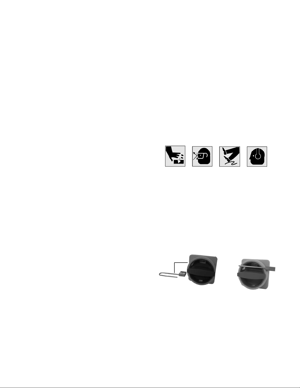
ON/OFF Switch Padlock
For Model Numbers A5816 and A5818
To avoid accidental starting by young children or
others not qualified to use the tool, the use of a
padlock is required.
1. Open the padlock (Fig E).
2. Insert the thr ough hole in the switch cover.
3. Close the padlock (Fig F).
4. Place the key in a safe place.
Figure E Figure F
6
Page 7
Specifications
The JET 15-Inch Vari-Speed Drill Presses, Models
J-A3816, J-A5816, and J-A5818 provide drilling
speeds from 400 to 5,000 rpm. Simple handwheel
adjustment sets the speeds with an LED speed
display on the faceplate of the machine.
JET's 15-inc h vari-speed drill press provides a solid
base for drilling and offers a wide range of spindle
speeds. The large quill provides greater accuracy.
The large worktabl e prov i des the operat or wit h room
to work and ample support for the workpiece. The
drill press has a 3-inch diameter column for head
and table support. The 15-Inch Vari-Speed Drill
Press is equipped with a standar d table raiser.
Model J-A3816 J-A5816 J-A5818
Stock Number ............................................ 354500 ................................ 354550 ............................... 354551
Type ................................................... Floor Model ......................... Floor Model ......................... Floor Model
Motor:
Motor Speed (rpm) ............................ 1,725 rpm ............................1,725 rpm ........................... 1, 725 rpm
HP ............................................................ 1 HP ................................... 1 HP ................................... 1 HP
Power Rating ........................... 1 PH, 115/220V ................... 1 PH, 115/220V .................. 3 PH, 220/440V
Prewired 115V Prewired 115V Prewired 220V
Spindle speeds (rpm) ................... 400 to 5,000rpm ................ 400 to 5,000 rpm ................. 400 to 5,000 rpm
Capacities:
Cast iron ........................................ up to 5/8-in. ........................ up to 5/8-in. .......................... up to 5/8-in
Steel .............................................. up to 1/2-in. ......................... up to 1/2-in. ......................... up to 1/2-in.
Work Table Weight Cpcty. ...................... 90 lbs. ................................. 90 lbs. ................................. 90 lbs.
Drills to center ............................................... 15 in. ................................... 15 in. .................................. 15 in.
Quill diameter ........................................... 2-1/4 in. ............................... 2-1/4 in. ............................... 2-1/4 in
Quill travel ...................................................... 6 in. ..................................... 6 in. .................................... 6 in.
Spindle taper ................................ #2 Morse Taper ................... #2 Morse Taper .................. #2 Morse Taper
Dimensions:
Table (overall) ..................... 15-1/4 x 17-3/4 in. ............... 15-1/4 x 17-3/4 in. ............... 15-1/4 x 17-3/4 in.
Table (working area) ............ 11-1/4 x 14-1/2 in. ............... 12-1/2 x 14-1/2 in. ............... 12-1/2 x 14-1/2 in.
Table travel ........................................ 16-3/4 in. ............................. 16-3/4 in. ............................ 16-3/4 in.
Table T-slots ................................. two at 1/2 in. ........................two at 1/2 in. ....................... two at 1/2 in.
T-slot centers ..................................... 5-5/16 in. ............................. 5-5/16 in. ............................ 5-5/16 in.
Spindle to table .................................. 25-3/4 in. ............................ 25-3/4 in. ............................25-3/4 in.
Spindle to base .................................. 44-1/2 in. ............................. 44-1/2 in. ............................ 44-1/2 in.
Column diameter........................................ 3 in. ..................................... 3 in. .................................... 3 in.
Base (LxWxH) ............. 20-7/8x14-3/16x3-1/8 in. ......20-7/8x14-3/1 6x3-1/8 in . ..... 20-7/8 x14 -3 /1 6x3-1/8 in.
Base T-slots .................................. two at 1/2 in. ........................two at 1/2 in. ....................... two at 1/2 in.
Overall height ......................................... 67-1/2 in. ............................ 67-1/2 in. ............................ 67-1/2 in.
Net weight ................................................... 394 lb .................................. 426 lb ................................. 426 lb
7
Page 8
Introduction
This manual includes operating and
maintenance instructions for the JET 15-Inch
Vari-Speed Drill Presses, Models J-A3816, JA5816, and J-A 5818. Thi s manual al so incl udes
parts listings and illustrations of replaceable
parts.
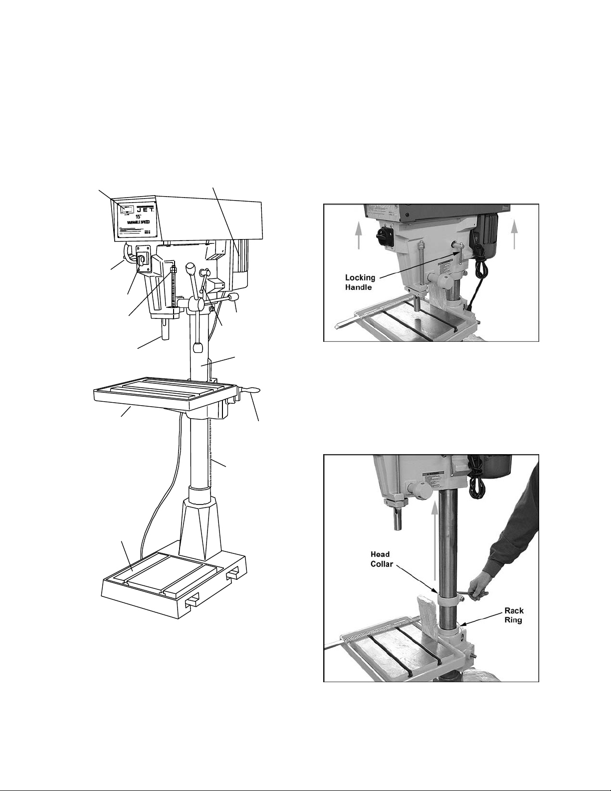
Refer to Figure 1 for key features of the drill
press.
LED Speed Display
Speed
setting
Handwheel
On/Off Switch
Depth Stop
Spindle
Motor
Feed Handle
Head locking
Handle
Column
solidly on the fl oor. Place shim s under the f our
mounting hol es in the base as requi red to level
the drill press.
Assembly
The Drill Press is shipped with the head in
lowered position. Follow these instructions to
assemble.
1. Figure 2: Loosen locking handle on head
and raise the head toward the top of the
column. NOTE: Use an assistant to help
raise the head. Re-tighten locking handle t o
secure head in position.
Figure 2
2. Figure 3: Use a wrench to loosen the hex
screw on the head c ollar, and raise the head
collar until it is contacting the head. Firmly
tighten the screw on the head collar.
Work Table
Base
Table
height
adjustment
Rack
Figure 1 – Drill Press Feat ur es
Set-up and Assembly
Securing the Base
The base of the drill press has four mounting
holes. The drill press should be level and rest
3. Figure 3: Loo sen the set screw on t he rack
ring and raise rack ring to allow clearance
for the rack. Re-tighten the set screw.
Figure 3
8
Page 9
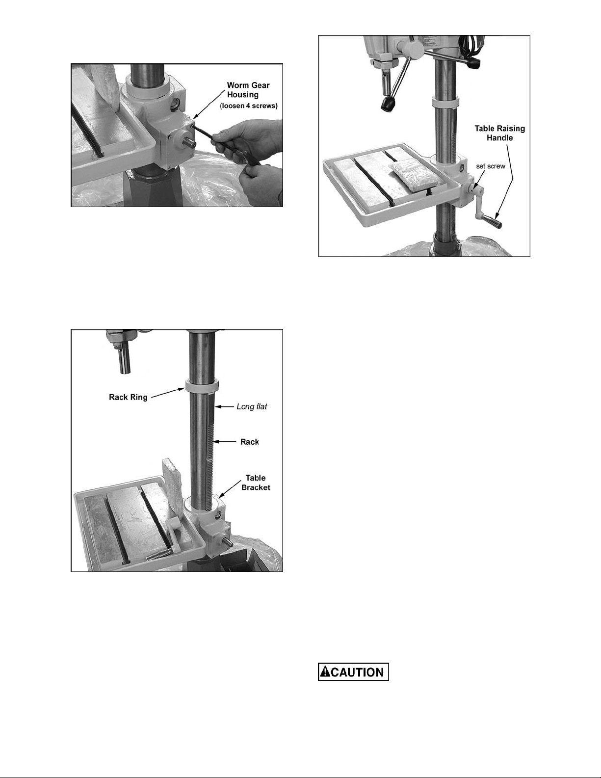
4. Figure 4: Loosen (do not remove) the four
screws in the worm gear housing.
Figure 4
5. Figure 5: P lace the rack against t he column
and slide it down as f ar as it will go into the
slot in the table bracket. (Position the rack
with the longer flat area toward the top and
the short fl at area toward the bot tom.)
6. Figure 5: S lide the rack ring down onto the
top of the rack and ti ghten the set screw on
the rack ring.
Figure 6
Cleaning
Clean off any protective grease with solvent.
After cleaning, lubricate the base, table, and
column with a light coating of medium weight
machine oil. Repeat at six months intervals.
Figure 5
7. Tighten the four screws in the worm gear
housing (show n in Figure 4).
8. Figure 6: I nstall the t able raising handl e and
tighten its set screw. Rotate the handle to
move the table up and down the column,
checking t hat movement is smooth and rack
has been correctly installed.
Internal part s of the drill press are lubri cated at
the fact ory. No further lubr ication is requir ed at
the time of installation.
Electrical Connection
Refer to the Wiring Diagram section for wiring
information. Connection to electrical power
should be made by a qualified electrician.
Observe l ocal electrical codes when connect ing
the machine.
The motor should be pr otect ed with a tim e del ay
fuse or ci rcuit breaker with an am perage rating
slightly higher than the full load current of the
motor.
Operating Controls
(Refer to Figure 7)
ON/OFF Switch
The ON/OFF switch is locat ed at the front of the
drill head.
Speed Control Handwheel
To avoid damage to the
speed adjustment mechanism, the motor
must be operating before attempting to
adjust the speed rate.
9
Page 10
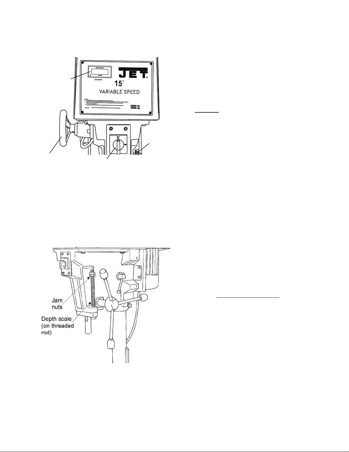
The speed control handwheel i s located on the
left side of the drill head. An LED speed
indicator is provided on the face plate on the dr ill
head.
LED Speed
Display
Depth
Stop
1. The head assembly must be locked to the
column so the thr ust produced by dri lling will
not force the head assembl y up the column.
2. The work table must be locked to the
column so it will not be forced down the
column.
3. Be sure the belt is tightened to the proper
tension.
4. DO NOT start to drill the workpiece until
making certain the workpiece is held down
securely.
5. BEFORE turning the speed control
handwheel in either direction.
6. Point of operation protection is required for
maximum safety. This remains the
responsibility of the user/purchaser since
conditions differ between jobs.
Speed control
Handwheel
Figure 7 – Operat ing Controls
On/Off Switch
Depth Stop
A drilling depth stop (refer to Figure 8) is
provided on the right side of the drill head. T he
depth stop consist s of a thr eaded rod with dept h
setting j am nuts. The front side of the threaded
rod has a depth scale. The jam nuts are
loosened and moved to the desired depth on the
scale. The upper jam nut is then tightened
against the l ower nut.
7. Make sure the drill is secured in the spindl e
or check before attempting to use the drill
press.
8. Make sure the spindle taper is clean and
free of burrs, scori ng, and galling to assure
maximum grippi ng.
Drilling Recommendations
Spe eds for Dr illing
The speed of a drill is usually measured in terms
of the rate at which the outer periphery of the
tool moves i n relation to t he work being dri lled.
The common term for this is Surface Feet per
Minute (SFM). The relationship of SFM is
expressed in the following formulas:
)(26.0 InchesinDiameterDrillRPMSFM ××=
RPM ×=
8.3
SFM
)(
InchesinDiameterDrill
Figure 8 – Depth Stop
Operating Precautions
The following operating and safety precautions
must be observed in or der to avoid harm to the
operator or damage t o the drill press.
10
In general, t he higher the speed the shorter the
drill lif e. Operating at the low end of the speed
range for a partic ular material will result in longer
life. The most eff ici ent speed for operating a drill
depends on many vari ables:
1. Composition and har dnes s of m aterial.
2. Depth of the hole.
3. Efficiency of t he cutting fluid.
4. Type and conditi on of the drilling machine.
5. Desired quali ty of the hole.
6. Difficulty of set-up.
Page 11

Indication of Extreme Speeds and Feeds
A drill t hat splits up the web is evi dence of too
much feed or insufficient tip clearance at the
center as a result of improper grinding. The
rapid wearing away of the ex treme outer corner s
of the cutti ng edges indicat es that the speed is
too high. A dr ill chipping or breaki ng out at the
cutting edges indicates that either the feed is too
heavy or the drill has been ground with too much
tip clearance.
Speeds for High Speed Steel Drills
4. Remove belt. (W ith speed control setti ng at
the highest speed, the belt should be l oose
enough to remov e.)
5. Install the replacement bel t. Install the head
cover.
6. Connect elect rical power to the drill press.
7. Operate the drill press to verify correct
operation.
Replacement of Motor
Material Speed In SFM
Alloy Steel — 300 to 400 Brinell ..................... 20 - 30
Stainless Steel............................................... 30 - 40
Automotive Steel Forgi ngs ............................. 40 - 50
Tool Steel, 1.2C ............................................. 50 - 60
Steel, .4C to .5C ............................................ 70 - 80
Mild Mach in e ry Ste e l , .2C to .3C .................. 80 - 110
Hard Chilled Cast Iron ................................... 30 - 40
Medium Hard Cast Iron ................................ 70 - 100
Soft Cast Iron ........................................... 100 – 150
Malleable Iron ............................................... 80 – 90
High Nickel Steel or Monel ............................ 40 – 50
High Tensile Bronze ..................................... 70 -150
Ordinary Brass and Bronze ........................ 200 - 300
Aluminum and it s Alloys ............................. 200 - 300
Magnesium and it s Alloys .......................... 250 - 400
Slate, Marble, and Stone ................................ 15 -25
Plastic s and similar m aterial (Bakelite) ....... 100 - 150
Wood ......................................................... 300 -400
Titanium Alloys .............................................. 10 - 25
Titanium Alloy Sheet ...................................... 50 - 60
General Applications
5mm hole .................................................. 550 - 600
10mm hole ................................................ 250 - 300
15mm hole ................................................ 100 - 110
In cases where carbon steel dr ills are appli c able,
the drill should be run at speeds of from 40 to 50
percent of those given above.
elec-trical power to the drill press to avoid
the possibility of inadvertent operation and
expo-sure to poten tially lethal voltage level s.
1. Disconnect el ec trical power to drill press.
2. Remove drive belt (see Replacement of Drive
Belt).
3. Di sconnect electrical wiring from motor j unction
box.
4. Remove nuts and washers from bolts
securing motor to drill head. Remove motor.
5. Remove pulleys and related components
from moto r s h a ft.
6. Install pulleys and related components on
replacement motor shaft.
7. Instal l motor on mounting bolts and secure
with nuts and washers.
8. Connect electrical wiring (refer to Wiring
Diagram section f or wiri ng details).
9. Install drive belt (see Replacement of Drive
Belt).
10. Operate drill press to verify proper
operation.
Make sure to disconnect
Lubrication
Maintenance
Replacement of Drive Belt
Make sure to disconnect
elec-trical power to the drill press to avoid
the possibility of inadvertent operation and
expo-sure to poten tially lethal voltage level s.
1. St art drill press. Set speed cont rol to highest
speed. Stop drill pr ess.
2. Disconnect el ec trical power to drill press.
3. Remove head cover.
11
Following are lubrication recommendations for
drill press component s.
Spindle pulley drive: Lubricate spindle
splines occasional ly with light grease.
Quill, Table, and Column: Lubricate with
light film of oil.
Table lift rack: Lubricate regularly with
SAE20 oil (clean rack with solvent before
applying oil.)
Variable speed driv e fork: Lubr icate contact
points occasionally with grease.
Page 12

Adjustments
Table Adjustment
The table can be raised or lowered to
accommodate the height of the component
being drilled (refer to Figure 9). To raise or
lower the table, loosen the lock handle. Then
use the hand crank to move the table to the
desired height. Then retighten the lock handle.
Figure 9 – Table Adjustment
Head Adjustment
Change th e radial position of
the drill head only if the drill press base is
secured to t he floor. Swinging the d rill head
without the base being secured to the floor
will cause the d rill press to beco me unstable
and tip over resulting in injury and/or
damage to the machine.
The radial position of the drill head can be
changed to accommodate the drill ing of a hole
that may be off set from the cent er of the table.
Reposition the drill head by loosening the
locking handles and swinging the drill head to
the desired posi tion. Then reti ghten the locki ng
handles.
Wiring Diagrams
Refer to Figure 5 for wiring information. The
drive motor is115/230 volt single phase or
220/440 volt three phase. Notice: When
converting machine voltage, it is necessary to
re-wire the LED di splay connection accor dingly.
Refer to figur e 10.
Figure 10
12
Page 13

Electrical
230 Volt Operation
115 Volt Operation
Referring to Fi gur e 11:
As received f rom the factory, your drill press is
ready to run at 115-volt operation. This drill
press, when wired for 115 volt, is intended for
use on a circuit t hat has an outlet and a plug that
looks li ke the one illustrated in ( A). A temporary
adapter, which looks like the adapter shown in
(B), may be used to connect this plug to a twopole receptacle if a properly grounded outlet is
not available. The temporary adapter should
only be used until a properly grounded outlet
can be installed by a qualified electrician. The
green colored rigid ear, lug, or tab, extending
from the adapter, must be connected to a
permanent gr ound such as a properly grounded
outlet box.
Referring to Fi gur e 12:
If 230V, single-phase operation is desired, the
following inst r uc tions must be followed:
1. Disconnect the machine from the power
source.
2. The JET drill press motor has four
numbered leads that are factory connected
for 115V operation, as shown in (A). For
230V operation reconnect the leads as
shown in (B).
3. The 115V attac hm ent plug (C), supplied with
the drill press, must be replaced with a UL
listed plug suitable for 230V operation (D).
Contact your local Authorized JET Service
Center or qualified electrician for proper
procedures to install the plug. The drill
press must comply with all local and nat ional
codes after the 230-volt plug is installed.
4. The drill press with a 230-volt plug should
only be connected to an outlet having the
same configuration as shown in (D). No
adapter is av ailable nor should be used with
the 230-volt plug.
A
B
Figure 12
Permanently Connected Tools
Figure 11
Models J-A3816, J-A5816 and J-A5818 drill
presses that are intended for permanent
connection shoul d be connected to a grounded
metal permanent wiring system or to a system
having an equipment-grounding conductor.
13
Page 14

Grounding Instructions
Extens ion Cords
This tool must be grounded
while in use to protect the operator from
electric shock.
In the event of a malfunction or breakdown,
grounding prov i des a path of least resistanc e f or
electric current to reduce the risk of electric
shock. This tool is equipped with an electric
cord having an equipment-grounding conductor
and a grounding plug. The plug must be plugged
into a matching outlet that is properly installed
and grounded in acc orda nce with al l l ocal codes
and ordinances.
Do not modify the pl ug provided. If it will not fit
the outlet , have the proper outlet i nstalled by a
qualified elec trician.
Improper connection of the equipmentgrounding conductor can result in a risk of
electric shock. The conductor, with insulation
having an outer surface that is green with or
without yellow stripes, is the equipmentgrounding conduct or. If repair or replacement of
the electric cord or plug is necessary, do not
connect the equipment-grounding conductor to a
live terminal.
Check with a qualified electrician or service
personnel if the grounding instructions are not
completely understood, or if in doubt as to
whether the tool is properl y grounded. Use onl y
three wire ex tension cords that have three-prong
grounding plugs and t hree-pole recept acles that
accept the tool ’s pl ug.
Make sure your extension cord is in good
condition. When using an extension cord, be
sure to use one heavy enough to carry the
current your machine will draw. An undersized
cord will cause a drop in the line voltage
resulting in power loss and overheating. The
table following shows the correct size to use
depending on the cord length and name plate
ampere rati ng. If in doubt, use the next heavi er
gauge. Remember, the smaller the gauge
number, the heavier the cord.
Length of Cord AWG
0–25 16
25-50 14
51-100 12
The drill press with a 230-v olt plug should only
be connected to an outlet having the same
configuration (D, Fig. 12). No adapter is
available or should be used with the 230-volt
plug.
Important: In all cases (115 or 230 v olt s), m ake
certain the receptacle in question is properly
grounded. If you are not sure, have a r egistered
electrici an c hec k the rec eptacle.
Repair or replace a damaged or worn cord
immediately.
14
Page 15

Troubleshooting
Problem Probable Cause Suggested Remedy
Spindle does
not turn.
Spindle noisy. Damaged spindle bearings.
Drill stalls . Worn drive belt.
Poorly drilled
holes.
Circuit breaker tripped.
Branch circuit breaker tripped or fuse
blown.
Open wire in switch circ uit.
Defective switch.
Broken drive
Worn spline.
Excessive feed rate for size of drill and
material being drilled .
No c utting fluid or i mpro per cut ting f luid.
Drill dull
Lack of rigidity in hold-down method.
Speed too fast for material and drill size.
Feed too fast for material and drill size.
No or improper cutting fluid or coolant
being used.
Improperly ground drill bit.
belt.
Reset circuit breaker.
Reset branch circuit breaker/replace fuse.
Repair open circuit.
Repair switc h.
Replace drive belt.
Replace bearings.
Replace spline.
Check condition of belt. Replace if glazed or
slipping on pulleys
Reduce feed pressure or use cutting fluid
Use c orr ect cuttin g flui d.
Sharpen drill.
Check that all T-slot hold-downs are tight and that
table-lock and drill head bolts are tight.
Check spindle speed recommendations. Reduce
speed if necessary.
Reduce feed rate.
Use cutting fluid, or change to proper fluid or
coolant for material being drilled.
Check for proper angles and reliefs. Regrind to
proper geometry.
Motor
overheating
Table cannot
be raised.
No s peed
readout.
Electrical circuit fault.
Oversize d rill.
Excessive feed.
No c utting fluid, or wrong fluid
Lack of lubrication Lubricate.
Speed pickup out of adjustment or failed. Adjust gap between speed pickup and post spindle
Check current draw in circuit. Make sure current
draw is the same as rating on motor plate.
Reduce drill size.
Reduce feed rate.
Use c orr ect cuttin g flui d for t he material and drill.
pulley. If there is no readout on the speed
indicator, replace the speed pickup.
Parts
Ordering Replacement Parts
To order parts or reac h our serv i ce depar tment, call 1-800-274-6848 M onday t hrough Fr iday (see our websi te f or
business hours, www.jettools.com). Having the Model Number and Serial Number of your machine available
when you call will allow us to serve you quickly and accurately .
15
Page 16
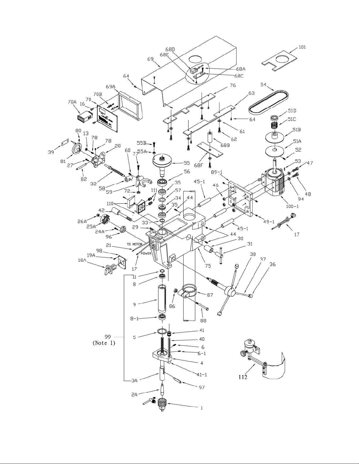
Exploded View — Head Models J-A5816 and J-A5818
16
Page 17

Parts List - Head Models J-A5816 and J-A5818
Item Part No. Description Size Qty.
1 ............... 5507580...................Chuck (with Key) ................................................................................... 1
2A ............ 5507495...................Arbor ..................................................................#2 MT x JT3 ............... 1
3A ............ 5507496A ................Spindle .................................................................................................. 1
4 ............... J-5053070 ................Quill Band.............................................................................................. 1
5 ............... 9010541...................O-Ring ................................................................................................... 1
6 ............... 9054511...................Set Screw ...........................................................5/16-18 x 3/8 .............. 2
6-1............ 9054511A ................Flat Head Screw .................................................M6x16 ........................ 1
7 ............... 5032611...................Bearing Retainer ................................................................................... 1
8 ............... 9100331...................Bearing...............................................................6203ZZ....................... 1
8-1............ 9100331A ................Bearing...............................................................6204ZZ....................... 1
9 ............... 5041010...................Quill ...................................................................................................... 1
10 ............. 9058561...................Wavy Spring Washer ............................................................................. 1
11 ............. 9074081...................Truarc Retainer .................................................................................... 1
13 ............. 9056981...................Hex Jam Nut ......................................................1 /4 - 2 0 ......................... 3
16 ............. 5518170...................Sloted Self Tapping Screw ..................................3/16-24 x 3/8 .............. 4
17 ............. 5518157...................Power Cord (1-Phase) ........................................................................... 1
17A .......... 5517463...................Power Cord (3-Phase) ........................................................................... 1
18A .......... 5507500...................Switch (Single Phase)............................................................................ 1
................. 5507497...................Switch (3-Phas e) ................................................................................... 1
19A .......... 5507501...................Slotted Machine Screw .......................................1/4-20 x 1 ................... 4
21 ............. 5518158...................Wiring Harness (1-Phase) ...................................................................... 1
................. 5517457...................W iring Harness (3-Phase) ...................................................................... 1
24A .......... 5507502...................Socket Head Cap Screw ........................................................................ 3
25A .......... 5507503...................Return Spring Assemlby ........................................................................ 1
26A .......... 5507504...................Nylon Nut .............................................................................................. 1
27 ............. 9135311...................Lock Screw .........................................................1/4-20 x 1 ................... 2
28 ............. J-5041050
29 ............. 9127731...................Socket Set Screw ...............................................5/16-18 x 5/16 ............ 1
30 ............. 5024541...................Head Lock (Plain Side) .......................................................................... 1
31 ............. 1000772...................Lock Nut Assembly ................................................................................ 1
32 ............. 5041071...................Speed Change Shaft ............................................................................. 1
33 ............. 9053661...................Retaine r ................................................................................................ 1
34 ............. 5041201...................Bearing Spacer ...................................................................................... 1
35 ............. 9100321...................Bearing .................................................................................................. 2
36 ............. 9070291...................Knob ..................................................................................................... 3
37 ............. 5053000...................Spoke .................................................................................................... 3
38 ............. J-5507827 ................Feed Shaft Assembl y............................................................................. 1
39 ............. 5513378...................Hi/Lo Speed Direction Plate ................................................................... 1
40 ............. 5053100A ................Rod, Graduated ..................................................................................... 1
41 ............. 9056381...................Jam Nut ..............................................................5/8-11 ......................... 3
41-1 .......... 9056381A ................Nut M10xP1.5/Spring Washer M10 ........................................................ 1
42 ............. 9128611...................Hex Head Cap Screw .........................................1/2-12 x 4 ................... 1
44 ............. TS-0270031 .............Set Screw ...........................................................5/16-18 x 3/8 .............. 4
45-1 .......... 5032781-1 ...............Motor Plate Bar
46 ............. 9057111...................Whiz Flange Locknut ............................................................................. 4
47 ............. TS-0152051 .............Carriage Bolt .....................................................5/16-18 x 2 ................. 2
48 ............. 9056171...................Carriage Bolt ......................................................5/16-18 x 1-1/2 ........... 4
49-1 .......... 9058051-1 ................Set Screw
51A .......... A5816-51A ...............Lower Pulley .......................................................................................... 1
51B .......... A5816-51B ...............Upper Pulley .......................................................................................... 1
51C .......... A5816-51C ..............Spring .................................................................................................... 1
51D .......... A5816-51D ..............Spring Support Cover ............................................................................ 1
52 ............. 9054621...................Socket Set Screw ..............................................1/4-20 x 1/2 ................ 2
53 ............. 5042011...................Key (Motor) ........................................................................................... 1
54 ............. 9077101...................Variable Speed Belt ............................................................................... 1
................Speed Change Housing ......................................................................... 1
(serial no: 11110696 and higher) ....................................... 4
(serial no: 11110696 and higher) .............5 /16” .......................... 4
17
Page 18

Parts List - Head Models J-A5816 and J-A5818
Item Part No. Description Size Qty.
55 ............. 5041140...................Vaiable S peed Pulley (Spindle) .............................................................. 1
55A .......... 5513510...................Hex Nut ................................................................................................ 1
55B .......... 5513511...................Socket Head Cap Screw ....................................................................... 1
56 ............. 9100421...................Bearing .................................................................................................. 1
57 ............. 9058571...................Spring Was he r ...................................................................................... 1
58 ............. 5041761...................Speed Change Nut ................................................................................ 1
59 ............. 5041040...................Speed Change Lever ............................................................................. 1
60 ............. 9127951...................Socket Set Screw ............................................... 1/4-20 x 1/2 ............... 1
61 ............. 9057461...................Washer............................................................... 1/4 ............................. 3
62 ............. 9052101...................Hex Head Cap Screw ........................................1/4-20 x 1 ................... 4
63 ............. J-5041271 ................Right Mounting Plate ............................................................................. 1
64 ............. 5518170...................Self Tapping Screw ...........................................3/16-24 x 3/8 .............. 7
68A .......... TS-0208041 ...........Socket Head Cap Screw .....................................5/16-1 8x3/4 ................ 2
68B .......... 5513513...................Spacer, Threaded .................................................................................. 1
68C .......... 5513514...................Plate, Bracket ........................................................................................ 1
68D .......... 5513515...................Pickup, Magnetic ................................................................................... 1
68E .......... 5513516...................Screw .................................................................................................... 2
68F........... 5513521...................Plate ...................................................................................................... 1
69 ............. J-5041320 ................Cover, Pulley ......................................................................................... 1
69A .......... J-5513517 ................Bracket, Face Plate ............................................................................... 1
70 ............. J-5513518 ................Plate, Face ............................................................................................ 1
70A .......... 5513519...................LED Display 1Ph ................................................................................... 1
................. 5513736...................LED Display 3 Ph ....................................................................................
70B .......... 5513520...................Screw, Locking ...................................................................................... 2
72 ............. 9056771...................Hex Jam Nut ......................................................3 /8 - 1 6 ......................... 1
75 ............. J-5041000
76 ............. J-5518172 ................Left Mounting Plate ................................................................................ 1
77 ............. 9052831...................Socket Set Screw ...............................................3/8-16 x 1 ................... 1
78 ............. TS-0267101 .............Socket Set Screw ...............................................1/4-20 x 1-1/4 ............. 2
80 ............. 9052971...................Socket Set Screw ..............................................5/16-18 x 5/16 ............ 1
81 ............. 5034111...................Hand Wheel .......................................................................................... 1
82 ............. 5513737...................Shaft speed change lever ...................................................................... 1
86 ............. 9129051...................Hex Nut ..............................................................7/16-14 ....................... 1
87 ............. 5041470...................Collar .................................................................................................... 1
88 ............. 9128071...................Hex Head Cap Screw ........................................7/16-14 x 3-1/2 ........... 1
89-1 .......... J-5032560-1.............Motor Mounting Bracket
94 ............. TS-0680032 .............Washer...............................................................5/16 ............................ 8
96 ............. 5507505...................Return Spring Bracket ........................................................................... 1
97 ............. 5507507...................Drift Pin ................................................................................................. 1
98 ............. 5507506...................Switch Mounting Plate ........................................................................... 1
99 ............. 5507527A ................Quill Assembly (see Note) ..................................................................... 1
100 ........... J-A5816-100-1-1 ......Motor, 1 PH 115/220...........................................1725 RPM 60 Hz ........ 1
................. A5816-100-2 ............Motor, 1PH 115/220 ...........................................1725 RPM 50 Hz ....... 1
................. J-A5818-100-1 .........Motor, 3 PH 220/440...........................................1725 RPM 50/60 Hz .. 1
101 ........... A5816-01 .................Motor Plate ............................................................................................ 1
110 ........... A5816-02 .................Connect Box .......................................................................................... 1
111 ........... A5816-03 .................Strain Relief ........................................................................................... 1
112 ........... 32104A ....................Safety Shield Assembly (For 15” DP) ..................................................... 1
Note: ....... Quill assembly includes items 3A, 5, 8, 8-1, 9, and 11.
................Head Casting......................................................................................... 1
(Serial no: 11110696 and higher) .......................... 1
18
Page 19
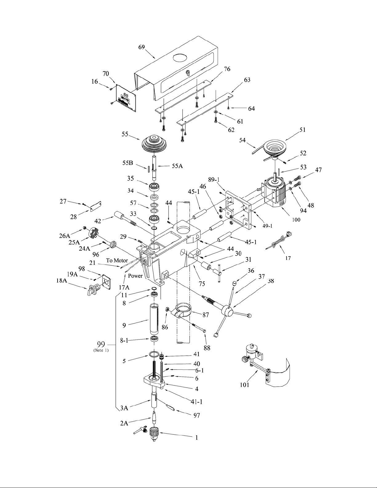
Exploded View — Head Model J-A3816
19
Page 20

Parts List - Head Model J-A3816
Item Part No. Description Size Qty.
1 ............... 5507580...................Chuck (with Key) ................................................................................... 1
2A ............ 5507495...................Arbor ..................................................................#2 MT x JT3 .............. 1
3A ............ 5507496A ................Spindle Asse mbly ................................................................................. 1
4 ............... J-5053070 ................Quill Band.............................................................................................. 1
5 ............... 9010541...................O-Ring ................................................................................................... 1
6 ............... 9054511...................Set Screw ...........................................................5/16-18 x 3/8 .............. 2
6-1............ 9054511A ................Flat Head Screw .................................................M6 x 16 ...................... 1
7 ............... 5032611...................Bearing Retainer ................................................................................... 1
8 ............... 9100331...................Bearing...............................................................6203ZZ....................... 1
8-1............ 9100331A ................Bearing...............................................................6204ZZ....................... 1
9 ............... 5041010...................Quill ...................................................................................................... 1
10 ............. 9058561...................Wavy Spring Washer ............................................................................. 1
11 ............. 9074081...................Truarc Retainer .................................................................................... 1
13 ............. 9056981...................Hex Jam Nut ......................................................1 /4 - 2 0 ......................... 3
16 ............. 9052711...................Self Tapping Screw ............................................8-32 x 3/8 ................... 4
17 ............. 5518157...................Power Cord (Single Phase) ................................................................... 1
17A .......... 5517463...................Power Cord (3-Phase) ........................................................................... 1
18A .......... 5507500...................Switch (Single Phase)............................................................................ 1
................. 5507497...................Switch (3-Phas e) ................................................................................... 1
19A .......... 5507501...................Slotted Machine Screw .......................................................................... 4
21 ............. 5518158...................Wiring Harness (1-Phase) ...................................................................... 1
................. 5517457...................W iring Harness (3-Phase) ...................................................................... 1
24A .......... 5507502...................Socket Head Cap Screw ........................................................................ 3
25A .......... 5507503...................Return Spring Assemlby ........................................................................ 1
26A .......... 5507504...................Nylon Nut .............................................................................................. 1
27 ............. 5518159...................Phillips Screw .....................................................1/4-20 x 5/16 .............. 2
28 ............. 5518160
29 ............. 9127731...................Socket Set Screw ...............................................5/16-18 x 5/16 ............ 1
30 ............. 5024541...................Head Lock (Plain Side) .......................................................................... 1
31 ............. 1000772...................Lock Nut Assembly ................................................................................ 1
33 ............. 9053661...................Retaine r ................................................................................................ 1
34 ............. 5041201...................Bearing Spacer ...................................................................................... 1
35 ............. 9100321...................Bearing .................................................................................................. 2
36 ............. 9070291...................Knob ..................................................................................................... 3
37 ............. J-5053000 ................Spoke .................................................................................................... 3
38 ............. J-5507827 ................Feed Shaft Assembl y............................................................................. 1
40 ............. 5053100A ................Rod, Graduated ..................................................................................... 1
41 ............. 9056381...................Jam Nut ..............................................................5/8-11 ......................... 3
41-1 .......... 9056381A ................Nut ….M10xP1.5/Spring Washer ........................M10 ............................ 1
42 ............. 9128611...................Hex Head Cap Screw .........................................1/2-13 x 4 ................... 1
44 ............. 9052191...................Socket Set Screw ...............................................5/16-18 x 1/2 .............. 4
45-1 .......... 5032781-1 ...............Motor Plate Bar
46 ............. 9057111...................Whiz Flange Locknut ............................................................................. 4
48 ............. 9056171...................Carriage Bolt ......................................................5/16-18 x 1-1/2 ........... 4
49-1 .......... 9058051-1 ...............Set Screw
51 ............. 5518161...................Step Pulley (Motor) ................................................................................ 1
52 ............. 5518162...................Socket Set Screw ...............................................1/4-20 x 5/16 .............. 2
53 ............. 5042011...................Key (Motor) ........................................................................................... 1
54 ............. 5518163...................Drive Belt..............OPTI VARIO 22x8x1140 or PYRA MID 1422V 470 .... 1
55 ............. 5518164...................Step Pulley (Spi ndle) ............................................................................. 1
55A .......... 5518165...................Spindle Pulley S h aft .............................................................................. 1
55B .......... 5518166...................Key.....................................................................5 x 45 ......................... 1
57 ............. 9058571...................Spring Was he r ...................................................................................... 2
61 ............. 9057461...................Washer...............................................................1/4 .............................. 3
62 ............. 9052101...................Hex Head Cap Screw .........................................1/4-20 x 1 ................... 4
63 ............. J-5518167 ................Mounting Plate ...................................................................................... 1
...................Cover Pla te ........................................................................................... 1
(Serial no: 11110696 and higher) ....................................... 4
(Serial no: 11110696 and higher) ............5 /16” ........................... 4
20
Page 21

Parts List - Head Model J-A3816
Item Part No. Description Size Qty.
64 ............. 9138011...................Self Tapping Screw ............................................#10 x 3/4 Type A ........ 4
69 ............. J-5518168 ................Pulley Cover (w/door & latch) ................................................................. 1
70 ............. J-5518169 ................Face Plate ............................................................................................. 1
75 ............. J-5041000 ................Head Casting......................................................................................... 1
76 ............. J-5518167L ..............Left Mounting Plate ................................................................................ 1
86 ............. 9129051...................Hex Nut ..............................................................7/16-14 ....................... 1
87 ............. J-5041470 ................Collar .................................................................................................... 1
88 ............. 9128071...................Hex Head Cap Screw ........................................7/16-14 x 3-1/2 ........... 1
89-1 .......... J-5032560-1.............Motor Mounting Bracket
94 ............. 9055281...................Rubber Washer ..................................................................................... 4
96 ............. 5507505...................Return Spring Bracket ........................................................................... 1
97 ............. 5507507...................Drift Pin ................................................................................................. 1
98 ............. 5507506...................Switch Mounting Plate ........................................................................... 1
99 ............. 5507527A ................Quill Assembly (see Note) ..................................................................... 1
100 ........... J-5507812 ................Motor, 1 PH 115/220...........................................1725 RPM 60 Hz ........ 1
................. J-5514604 ................Motor, 1PH 115/220 ...........................................1725 RPM 50 Hz ....... 1
................. J-5507813 ................Motor, 3 PH 220/440...........................................1725 RPM 50/60 Hz .. 1
101 ........... 32104A ....................Safety Shield Assembly (For 15” DP) ..................................................... 1
Note: Quill assembly includes items 5, 7, 8, 8-1, 9, 10 and 11.
(Serial no: 11110696 and higher) .......................... 1
21
Page 22
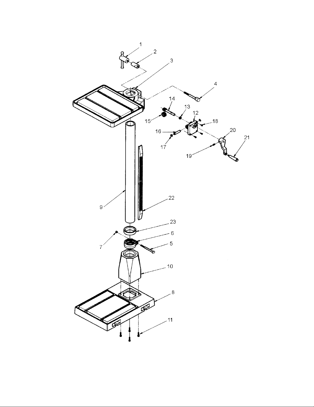
Exploded View – Base Floor Models J-A3816, J-A5816 and J-A5818
22
Page 23

Parts List – Base Floor Models J-A3816, J-A5816 and J-A5818
Item Part No. Description Size Qty.
1 ............... 1000772 .................. Lo cknut .............................................................. ................................... 1
2 ............... 5003751 .................. Table Lock (Plain Side) ...................................... ................................... 1
3 ............... J-5507508 ............... Tab le ................................................................. ................................... 1
4 ............... 5507509 .................. He x Head Cap Screw ........................................ ................................... 1
5 ............... TS-0061091 ............ Cap Screw ......................................................... 7/16-14 x 3-1/2 ........... 1
6 ............... J-5041470 ............... Co llar ................................................................. ................................... 1
7 ............... 9129051 .................. He x Nu t ............................................................. 7/16 -14 ....................... 1
8 ............... J-5507528 ............... Bas e .................................................................. ................................... 1
9 ............... 5507510 .................. Standard Column ............................................... ................................... 1
................. 5511850 .................. Short Column ..................................................... ................................... 1
10 ............. J-5507511 ............... Flange (Base/Column) ....................................... ................................... 1
11 ............. 5630771 .................. HHCS ................................................................ 1/2-12 x 1-1/2 ............. 4
12 ............. J-5507571 ............... Cover Plate ........................................................ ................................... 1
13 ............. 5507570 .................. Bus hing ............................................................. ................................... 1
14 ............. 5507513 .................. Worm, Table Raiser ........................................... ................................... 1
15 ............. 5507514 .................. Ge a r , Ta b le Raiser ............................................ ................................... 1
16 ............. 5507515 .................. Shaft, Table Raiser ............................................ ................................... 1
17 ............. 5507516 .................. C-Ring , Table Raiser ......................................... ................................... 2
18 ............. TS-0050051 ........... Socket Head Cap Scr ew .................................... 1/4 x 1 ........................ 4
19 ............. 5507518 .................. Socke t Head Set Scr ew ..................................... 5/16-18 x 3/8............... 1
20 ............. J-5507519 ............... Crank, Table Raiser ........................................... ................................... 1
21 ............. 5507520 .................. Handle, Table Raiser ......................................... ................................... 1
22 ............. 5507521 .................. Rack .................................................................. ................................... 1
23 ............. J-5507522 ............... Rack Ring .......................................................... ................................... 1
25 ............. 5507816 .................. Table Raiser Assembly (includes index# 12 thru 17) .............................. 1
23
Page 24
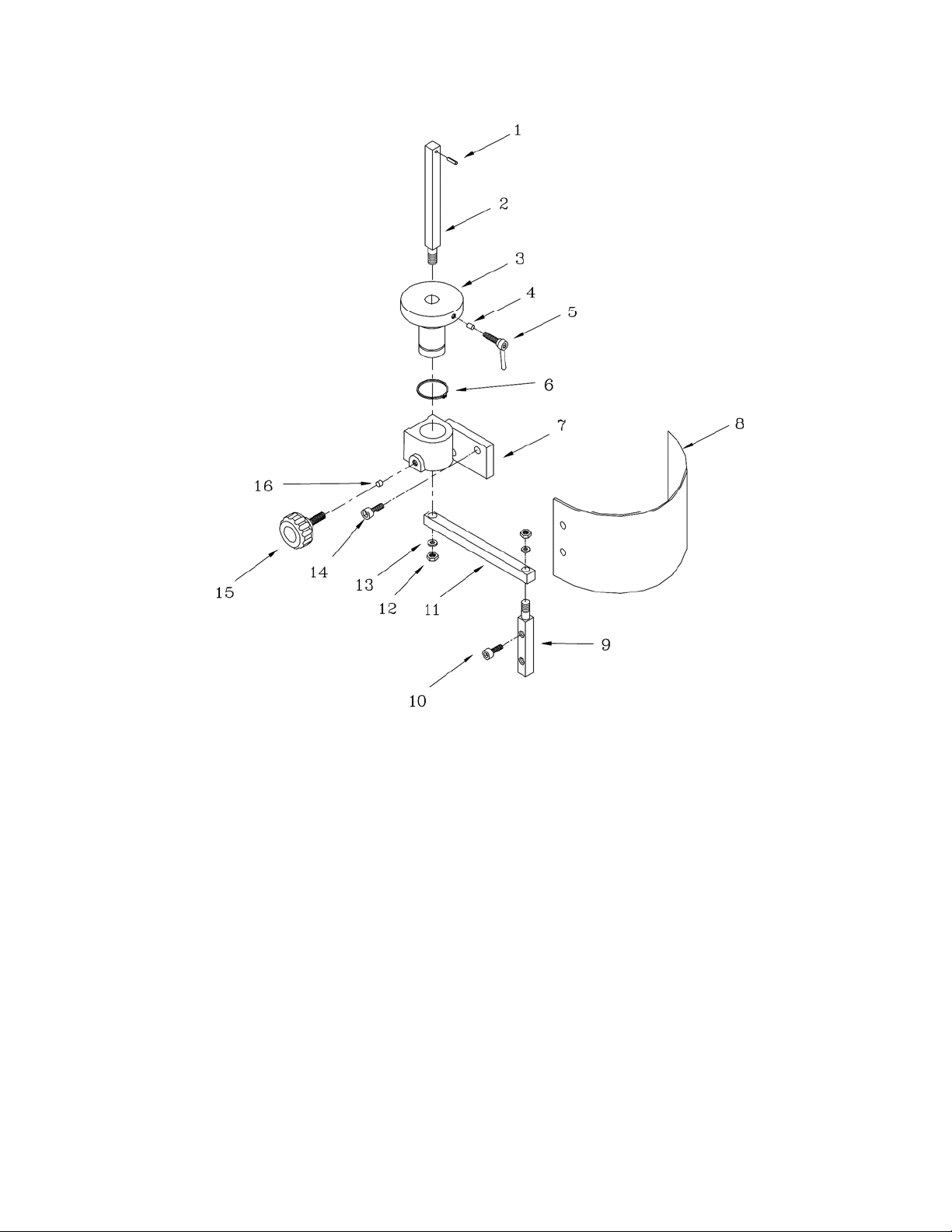
Exploded View – Safety Shield Assembly, Models J-A3816, J-A5816 and J-A5818
Parts List – Safety Shield Assembly (All Models)
Item Part No. Description Size Qty.
1 ............... 6293347 .................. Sp ring Pin .......................................................... 3x16 ........................... 1
2 ............... 32106A-2 ................ Support Bracket Bar........................................... ................................... 1
3 ............... 32106A-3 ................ Bush ing ............................................................. ................................... 1
4 ............... 32106A-4 ................ Space r ............................................................... ................................... 1
5 ............... 32106A-5 ................ Lock Handle ...................................................... M6x20 ........................ 1
6 ............... 32106A-6 ................ C-Clip ................................................................ S3 0 ............................. 1
7 ............... 32106A-7 ................ Bracke t .............................................................. ................................... 1
8 ............... 32104A-8 ................ Safety Shie ld ..................................................... 410x210mm ................ 1
9 ............... 32106A-9 ................ Lower Bracket Bar ............................................. ................................... 1
10 ............. TS-1504021 ............ Hex Socket Head Cap Screw ............................. M8x12 ........................ 1
11 ............. 32106A-11 .............. Support Arm ...................................................... ................................... 1
12 ............. TS-0640091 ............ Hex Nut ............................................................. 3/8 ” ............................. 1
13 ............. TS-0720091 ............ Spring Washer ................................................... 3/8 .............................. 1
14 ............. TS-1504041 ............ Hex Socket Head Cap Screw ............................. M8x20 ........................ 1
15 ............. 32106A-16 .............. Lock Bolt with Knob ........................................... M8 .............................. 1
16 ............. 32106A-17 .............. Spac er ............................................................... ................................... 1
24
 Loading...