

Page 1
This .pdf document is bookmarked
Operating Instructions and Parts Manual
20-inch Drill Press
Model: JDP -2 0MF
JET
427 New Sanford Road
LaVergne, Tennessee 37086 Part No. M-354170
Ph.: 800-274-6848 Revision H4 03/2014
www.jettools.com Copyright © 2014 JET
Page 2

Warranty and Service
JET warrants every product it sells against manufacturers’ defects. If one of our tools needs service or repair, please
contact Technical Service by calling 1-800-274-6846, 8AM to 5PM CST, Monday through Friday.
Warranty Period
The general warranty lasts for the time period specified in the literature included with your product or on the official
JET branded website.
• JET products carry a limited warranty which varies in duration based upon the product. (See chart below)
• Accessories carry a limited warranty of one year from the date of receipt.
• Consumable items are defined as expendable parts or accessories expected to become inoperable within a
reasonable amount of use and are covered by a 90 day limited warranty against manufacturer’s defects.
Who is Covered
This warranty covers only the initial purchaser of the product from the date of delivery.
What is Co vered
This warranty covers any defects in workmanship or materials subject to the limitations stated below. This warranty
does not cover failures due directly or indirectly to misuse, abuse, negligence or accidents, normal wear-and-tear,
improper repair, alterations or lack of maintenance.
Warranty Limitations
Woodworking products with a Five Year Warranty that are used for commercial or industrial purposes default to a
Two Year Warranty. Please contact Technical Service at 1-800-274-6846 for further clarification.
How to Get Technical Support
Please contact Technical Service by calling 1-800-274-6846. Please note that you will be asked to provi d e pr o of
of initia l p u rch a s e whe n calling. If a product requires further inspection, the Technical Service representative will
explain and assist with any additional action needed. JET has Authorized Service Centers located throughout the
United States. For the name of an Authorized Service Center in your area call 1-800-274-6846 or use the Service
Center Locator on the JET website.
More Information
JET is constantly adding new products. For complete, up-to-date product information, check with your local distributor
or visit the JET website.
How S tate Law Applies
This warranty gives you specific legal rights, subject to applicable state law.
Limitations on This Warranty
JET LIMITS ALL IMPLIED WARRANTIES TO THE PERIOD OF THE LIMITED WARRANTY FOR EACH PRODUCT.
EXCEPT AS STATED HEREIN, ANY IMPLIED WARRANTI ES OF MERCHANTABILITY AND FITNESS FOR A
PARTICULAR PURPOSE ARE EXCLUDED. SOME STATES DO NOT ALLOW LIMITATIONS ON HOW LONG AN
IMPLIED WARRANTY LASTS, SO THE ABOVE LIMITATION MAY NOT APPLY TO YOU.
JET SHALL IN NO EVENT BE LIABLE FOR DEATH, INJURIES TO PERSONS OR PROPERTY, OR FOR
INCIDENTAL, CONTINGENT, SPECIAL, OR CONSEQUENTIAL DAMAGES ARISING FROM THE USE OF OUR
PRODUCTS. SOME STATES DO NOT ALLOW THE EXCLUSION OR LIMITATION OF INCIDENTAL OR
CONSEQUENTIAL DAMAGES, SO THE ABOVE LIMITATION OR EXCLUSION MAY NOT APPLY TO YOU.
JET sells through distributors only. The specifications listed in JET printed materials and on official JET website are
given as general information and are not binding. JET reserves the right to effect at any time, without prior notice,
those alterations to parts, fittings, and accessory equipment which they may deem necessary for any reason
whatsoever. JET
Product Listing with Warranty Period
90 Days – Parts; Consumable items; Light-Duty Air Tools
1 Year – Motors; Machine Accessories; Heavy-Duty Air Tools; Pro-Duty Air Tools
2 Year – Metalworking Machinery; Electric Hoists, Electric Hoist Accessories; Woodworking Machinery used
for industrial or commercial purposes
5 Year – Woodworking Machinery
Limited Lifetime – JET Parallel clamps; VOLT Series Electric Hoists; Manual Hoists; Manual Hoist
Accessories; Shop Tools; Warehouse & Dock products; Hand Tools
NOTE: JET is a division of JPW Industries, Inc. References in this document to JET also apply to JPW Industries,
Inc., or any of its successors in interest to the JET brand.
®
branded products are not sold in Canada by JPW Industries, Inc.
2
Page 3

Table of Contents
Table of Contents .................................................................................................................................... 3
Warnings ................................................................................................................................................. 4
Specifica tions ................................................................................................................ .......................... 6
Shipping Contents ................................................................................................................................... 7
Required Tools (not included) .................................................................................................................. 7
Assembly ................................................................................................................................................ 8
Before Assembly .................................................................................................................................. 8
Column Assembly ................................................................................................................................ 8
Table Bracket ....................................................................................................................................... 8
Crank Handle ....................................................................................................................................... 9
Column Lock Handl e ............................................................................................................................ 9
Table Installation .................................................................................................................................. 9
Head Assembly .................................................................................................................................. 10
Chuck and Arbor Installation .............................................................................................................. 10
Chuck and Arbor Removal ................................................................................................................. 10
Chuck Guard ...................................................................................................................................... 11
Adjust ment ............................................................................................................................................ 1 1
Depth Stop Adjustment ...................................................................................................................... 11
Changing Spindle Speeds .................................................................................................................. 11
Return Spring Adjustment .................................................................................................................. 12
Work Light ......................................................................................................................................... 12
Table Til t Ad ju stment ......................................................................................................................... 12
Operation .............................................................................................................................................. 1 3
Installing Dril ls .................................................................................................................................... 13
Positioning the Workpiece .................................................................................................................. 13
Using the Vise .................................................................................................................................... 13
Basic Operation ................................................................................................................................. 13
Maintenance .......................................................................................................................................... 13
Lubrication............................................................................................................................................. 13
Electrical ............................................................................................................................................... 13
115 Volt Operati on ............................................................................................................................. 13
230 Volt Operati on ............................................................................................................................. 14
Grounding Inst r uc tions ....................................................................................................................... 14
Extension Cords................................................................................................................................. 14
Troubleshooting ..................................................................................................................................... 1 5
Replacement Parts............................................................................................................................. 16
Exploded View Drawing JDP-20M F .................................................................................................... 17
Parts List JDP-20MF .......................................................................................................................... 18
Wiring Diagram ...................................................................................................................................... 21
JDP-20MF Electri c al S c hem atic – 115V ............................................................................................. 21
JDP-20MF Electri c al S c hem atic – 230V ............................................................................................. 21
The specificati ons in thi s manual are given as general inf ormation and ar e not binding. JET reserv es the
right to eff ect, at any tim e and wit hout pri or notic e, changes or alt erat ions to par ts, fi tti ngs, and accessory
equipment deemed nec essary for any reason whatsoev er.
3
Page 4

Warnings
1. Read and understand the ent ire owner’s manual before attempting assembly or operation.
2. Read and understand the warnings po sted on the m achine and i n thi s manual. Fail ure to comply wit h
all of these warnings m ay cause seriou s i njury.
3. Replace the warning labels if they become obscured or removed.
4. This drill pr ess is designed and i ntended f or use by pr operl y tr ained and ex peri enced personnel only .
If you are not familiar with the proper and safe operation of a drill press, do not use until proper
training and knowledge have been obtained.
5. Do not use this drill press for other than its int ended use. If used for other pur poses, JET discl aims
any real or implied warrant y and holds itself harmless from any injury that may result from that use.
6. Always wear approv ed safety glasses/face shiel ds whil e using this drill press. Everyday eyegl asses
only have impact resi stant lenses; they are not safet y glasses.
7. Before operating this drill press, remov e tie, rings, watches and other jewelry, and roll sl eev es up past
the elbows. Remove all l oose clothing and confine long hair. Non-slip footwear or anti-skid f loor strips
are recommended. Do not wear gloves.
8. Wear ear protector s (plugs or muffs) during extended periods of operation.
9. Some dust created by power sanding, sawing, grinding, drilling and other construction activities
contain chemi cals known to cause cancer , bir th defects or other r eproductiv e harm . Some exampl es
of these chemic als are:
• Lead from lead based paint.
• Crystalli ne sil ic a from bricks, cement and other masonry pr oduc ts.
• Arsenic and chromium from chemically treated lumber.
Your risk of exposure varies, depending on how often you do this type of work. To reduce your
exposure to these chemicals, work in a well-ventilated area and work with approved safety
equipment, such as face or dust masks that are specifically designed to filter out microscopic
particles.
10. Do not oper ate this machine while tired or under the influence of drugs, alcohol or any m edi c ation.
11. Make c ertain the switch is in the OFF position before connecti ng the machine to the power supply.
12. Make c ertain the machine is properly grounded.
13. Make all machine adjustment s or maintenanc e with the machine unplugged from the power source.
14. Remove adjusting keys and wrenches. Form a habit of checking to see that keys and adjusting
wrenches are removed from the machine before turning i t on.
15. Keep safety guards in place at all times when the machine is in use. If removed for maintenance
purposes, use extreme caution and replace the guards immediately.
16. Make sure the drill press is firml y secured to the floor or bench before use.
17. Check damaged parts. Before further use of the machine, a guard or other part that is damaged
should be carefully checked to determine that it will operate properly and perform its intended
function. Chec k for alignment of moving par ts, binding of moving parts, breakage of parts, mounting
and any other condi ti ons that m ay affect its operati on. A guard or ot her part that i s damaged should
be properly repaired or replaced.
18. Prov ide for adequate space surrounding work ar ea and non-glare, over head lighting.
19. Keep t he floor around the machine clean and free of scrap mat er ial, oil and grease.
4
Page 5

20. Keep visitors a safe distance from the work area. Keep children away.
21. Make y our workshop child proof with padlocks, master switches or by removing starter keys.
22. Giv e your work undivi ded attention. Looki ng around, carryi ng on a conversati on and “horse-play” ar e
careless acts that can r esul t in serious injury.
23. Maintai n a bal anced stance at all times so that you do not f al l or lean against the spindle or other
moving part s. Do not over r eac h or use excessive force to perform any machine oper ation.
24. Use the right tool at the correc t speed and f eed rat e. Do not force a t ool or attac hment to do a job for
which it was not designed. T he ri ght tool will do the job better and saf er.
25. Use recommended accessories; improper accessories may be hazardous.
26. Maint ain tool s with care. Keep drill bit s sharp and clea n for t he best and safest perf ormance. Foll ow
instructions for lubricating and changing accessories.
27. Make sure the work pi ece is securel y attached or clamped to the table. Never use your hand to hol d
the work piece.
28. Tur n off the machi ne before cleaning. Use a brush or compressed air to remove chips or debris — do
not use your hands.
29. Do not stand on the machine. Serious injury c ould occur if the machine tips over.
30. Never leave the machine running unattended. Turn the power off and do not leave the machi ne until it
comes to a complete stop.
31. Remove loose items and unnecessary work piec es from the area before starti ng the mac hine.
Familiariz e you rself with the following safety notices used in this manual:
This means that if precautions are not heeded, it may result in minor injury and/or
possible machine damage.
This means that if precauti ons are not heeded, it may result in serious injury or possibly
even death.
- - SAVE THESE INSTRUCTIONS - -
5
Page 6

Specifications
Model Number .......................................................................................................................... JDP-20MF
Stock Num ber................................................................................................................................ 354170
Type .................................................................................................................................................. Flo or
Motor:
Horsepower................................................................................................................................. 1 -1/2
Phase ........................................................................................................................................ single
Voltage........................................................................................................115/230V ( prewired 115V)
Frequency .................................................................................................................................. 60 Hz
FLA (Full Load Amperage) ........................................................................................................ 18/9 A
Capacities:
Drills to Center Circl e ..................................................................................................................... 20”
Distance Column to Spi ndle ........................................................................................................... 10 ”
Drilling Capacity – Cast Iron ............................................................................................................. 1”
Drilling Capacity – Mild Steel ......................................................................................................... 3/4"
Chuck Size .................................................................................................................................... 3/4”
Speeds:
Number of Spindl e Speeds .............................................................................................................. 12
Range of Spindle Speeds (RPM ) ........................................................................................ 150 – 4200
Spindle:
Spindle Taper .............................................................................................................................. MT-3
Spindle Travel ............................................................................................................................ 4-5/8”
Spindle Distance to Base.......................................................................................................... 46-3/4 ”
Spindle Distance to Table (max.) .............................................................................................. 29-1/8”
Table and Column:
Table Size (Length x Widt h) ............................................................................................ 18-1/2" x 16"
Table Weight Capacity .................................................................................................................80 lb
Table T-Slots, Number ...................................................................................................................... 6
Table T-Slots, Size ........................................................................................................................ 1/2"
Table T-Slots, Centers................................................................................................................ 3-1/2”
Table Tilt ................................................................................................................................. 45 deg.
Column Diameter ....................................................................................................................... 3-3/8”
Base:
Base Size .................................................................................................................. 13-3/4” x 22-3/4”
Base Working Surface ....................................................................................................... 13” x 8-1/2”
Base Slots, Num ber .......................................................................................................................... 2
Base Slots, Size ............................................................................................................................ 5/8”
Dimensions:
Overall Dimensions (H x W x D) ....................................................................... 66" x 18-1/2" x 31-1/2"
Carton Size (L x W x H) : ............................................................................................... 26" x 13" x 58"
Weights:
Net Weight (approx.) ............................................................................................................... 282 lbs.
Gross Weigh t ......................................................................................................................... 293 l bs.
6
Page 7
Shipping Contents
Unpack the cart on and v erify that all part s listed
below are incl uded.
Main Parts
1 ea Head Assembly
1 ea Table
1 set Colum n and Table Bracket Assembly
1 ea Base
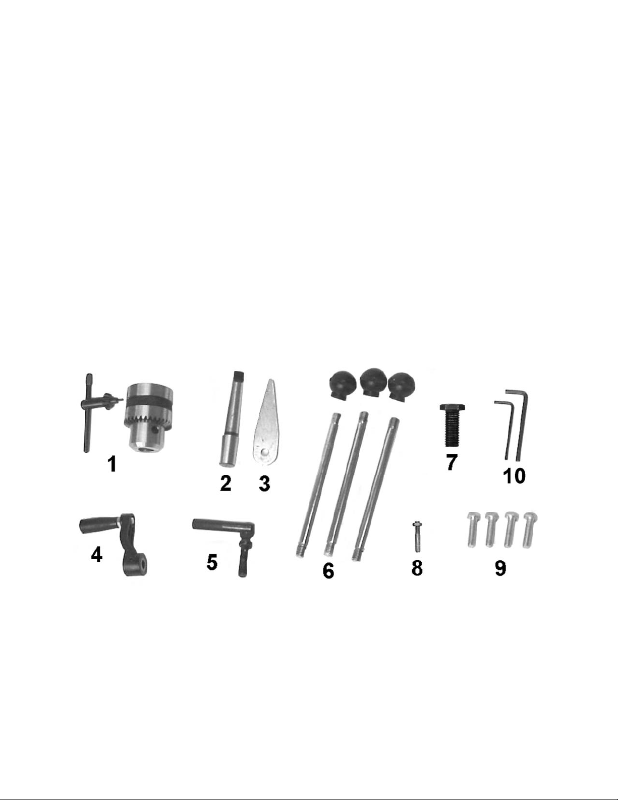
Additional Parts
1. 1 set Chuck and Chuck K ey
2. 1 pc Arbor
3. 1 pc Drift Key
4. 1 pc T able Crank Handle
5. 1 pc Column Lock Handle
6. 3 pcs Downfeed Handles and Knobs
7. 1 pc 5/ 8"-11x2" Hex Cap Screw
8. 1 set Locator P in and Hex Nut
9. 4 pcs M10 x 40 Hex Cap Screws
10. 2 pc Hex Wrenches (3mm, 5mm)
11. 1 pc Chuck Guard (not shown)
Other Material
1 ea Owner’s Manual
1 ea Warranty Registr ation Card
Required Tools (not included)
1. 17mm Box Wrench or a 6” – 8” Adjustable
Wrench
2. 15/16" wrench
Additional Parts
7
Page 8
Assembly
Read and understand all
assembly instructions before attempting
assembly! Failure to comply may cause
serious injury!
Do not attempt to turn on
power before this machine is completely
assembled.
Before Assembly
1. Remove the contents from the shipping
container.
2. Compare the contents of the shipping
container wit h the list on page 7. Report any
shortages or damage to your JET distributor.
3. Clean all rust protected surfaces with
kerosene or a light solvent. Do not use
lacquer thinner, paint thinner, or gasoline.
These will damage plastic components and
painted surfaces.
Column Assembly
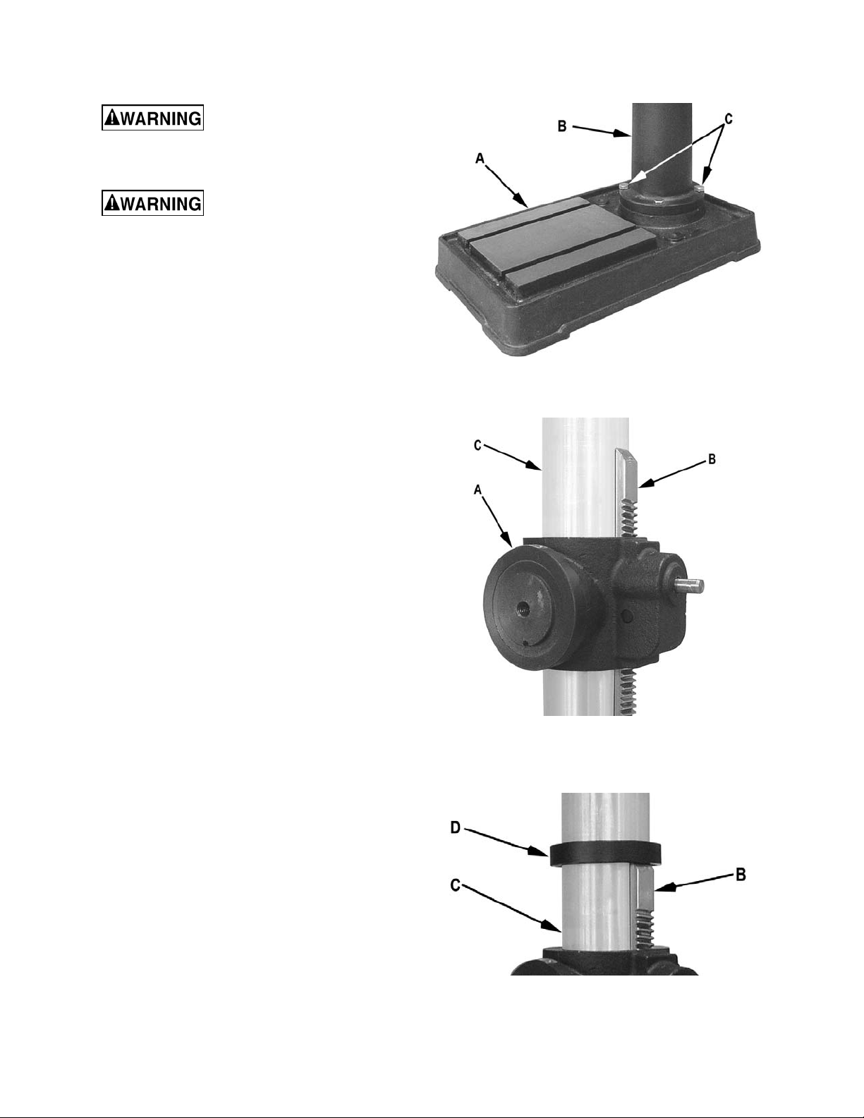
Referring to Fi gur e 1:
1. Place the base (A) on a level floor.
2. Place the column assembly (B) on the base
(A) and ali gn the holes in the c olumn support
with the holes i n the base.
3. Using a 17mm wrench, secure the col um n (B)
with four M10 x 40 hex cap screws (C) to t he
base.
Table Bracket
When shipped, the rack ring and rack are bundled
together with the column in plastic wrap.
Figure 1
Figure 2
Referring to Fi gur es 2 and 3:
1. Remove the wrap and take the rack ring ( D)
and rack (B) off the colum n ( C).
2. Install the table bracket (A) toget her with t he
rack (B) on the column (C) as shown in
Figure 2.
3. Slide the rack ring (D) over the column (C),
placing it so it rests against the rack (B) as
shown in Figure 3 and tighten firmly with a
3mm hex wrench (provi ded) .
Figure 3
8
Page 9

Crank Handle
Referring to Fi gur e 4:
1. Loosen the setscrew (B) on the table crank
handle (A).
2. Slide the handle (A) onto the table bracket
shaft.
3. Turn the handle until the setscrew i s opposite
the flat section on the shaft, and tighten the
setscrew to secure the handle.
Column Lock Handle
Referring to Fi gur e 5:
Thread the column loc k handle (A) into the table
bracket (B).
Table Installation
Figure 4
The table is heavy! This
installatio n is a two person operation to avoid
injury fro m accid ental d ropp ing.
Referring to Fi gur e 6:
1. Have one person hold the table (A) against
the bracket (B), aligning the hole in the
mounting pl ate of the table with t he threaded
hole in bracket .
2. Have the second person ins ert the 5/8"-11x2
hex head screw (C) through the opening on
the bottom side of the table (A) and start
threading the scr ew into the bracket by hand.
3. Finish ti ghtening the screw (C) with a 15/16"
or wrench (wrench provided) , but leave l oose
enough so the table can be til ted by hand.
4. Using the scale on the bracket as a guide, set
the table angle to 0 degrees (level).
5. Take the locator pin (D) and adjust the hex
nut towards the end of t he thread as shown in
the close up view (D).
6. Insert the non-threaded end of the l ocator pin
(D) into t he hol e on the t able found just belo w
the mounting screw. Press al l the way in.
Note: The tabl e m ay have t o be til ted sli ghtly
back and forth if t he holes do not quite align.
7. Tighten the screw (C) with a 15/16" wrench.
Figure 5
Figure 6
9
Page 10

Head Assembly
Referring to Fi gur e 7:
1. With t he aid of a second person, c arefully lift
the head onto the column top and slide it
down into position
The head assembly is heavy!
Use care when lifting onto th e col umn!
2. Rotate head assembly until si des of the pulley
cover are parall el with the sides of the base.
3. Tighten two setscrews (A) with a 5mm hex
wrench (provi ded) until they are snug.
4. Install three downfeed handles (B) into the
downfeed hub (C).
Chuck and Arbor Installation
Referring to Fi gur e 8:
1. Thoroughly clean the internal and external
taper of the arbor (A), and chuck (B) and
spindle (C).
Important: These three pieces must be f ree
of any rust pr otect i on, or l ubric ant. If they are
not clean, the ar bor and c huc k m ay fail to seat
in the spindle.
2. Place arbor (A) into the chuck (B).
3. Twist the chuck to f ully r etrac t t he c huc k jaws.
4. Place arbor and chuck assembly into the
spindle (C).
5. Turn the arbor and chuck assembl y until the
tang on the arbor en gages the slot at t he end
of the spindl e.
6. Use a few taps from a rubber mallet, or a
hammer and a block of wood, against the
bottom of the chuck to seat the chuck
securely onto t he arbor. Do not use a steel-
faced hammer directly against the chuck.
Figure 7
Figure 8
Chuck and Arbor Removal
1. Unplug machine from the power source.
2. Raise the tabl e until it is about seven inc hes
below the chuck.
3. Place a piece of scrap wood on the t abl e, and
lower quill (A, Fig. 9) using the downfeed
handle.
4. Rotate spindle to align the keyhole in the
spindle with t he k ey hole in the quill.
5. Insert the drift key (B, Fi g. 9) into t he aligned
slots and tap lightly. The chuck and arbor
assembly should fall from the spindle.
Figure 9
10
Page 11

Chuck Guard
1. Unplug machine fr om power source.
2. Attach chuck guard to spindle collar and
tighten screw (Fi gure 9a). The guard can be
flipped up for chuck ac c ess.
Adjustment
Depth Stop Adjustment
To drill multiple holes at the same preset depth,
use the depth stop:
1. Use a pencil to mark the dept h the bit will dri ll
into the workpiece.
2. With the drill bit in the chuck, lower downfeed
handle to advance bit to your mark (A, Fig.
10).
3. With your other hand, adv anc e the lock nuts
(B, Fig. 10) on the depth stop r od until they
are snug to the seat (C, Fi g. 10).
4. The drill bit will now adv anc e to t his poi nt.
5. To release, advanc e the nuts counter-
clockwise to t he top of the depth stop.
Figure 9a
Changing Spindle Speeds
A spindle speed and pulley/belt arrangement c hart
is found on the inside of the pulley cover (D,
Fig. 11), also shown in Figure 12. Refer to this
chart whenev er changing speeds.
To change spindle speeds:
1. Unplug the machine from the power source.
2. Loosen two bar knobs (E, Fig. 11) found on
each side of the head assembly.
3. Rotate the tension adjuster clockwise
(F, Fig. 11) to bring the motor base as close
to the head as possible.
4. For desired speed, change t he location of
belts per pulley /belt arrangement chart.
5. Rotate the tension adjuster counterclockwise
(F. Fig. 11) to tension t he belts.
6. Tighten two bar knobs (E, Fig. 11). Belts are
properly t ensi oned when finger and thumb
pressure mi dway between the t wo pulleys
causes approximately ½” deflection.
Figure 10
Figure 11
11
Page 12

Return Spring Adjustment
The return spring is adjusted at the factory and
should not need furt her adjustment. If adjustment
is deemed necessary, follow the steps below
while referri ng to Figure 12:
1. Unplug the machine from the power source.
2. Loosen two hex nuts (A). Do not remove.
Do not remove th e co il spring
cover (Step 3). The torsion spring will uncoil
and can cause seriou s injury.
3. Firmly hol d the coil spring cover (B).
4. Pull out the cover and rotate until the pin (C)
on the return spring plate engages the next
notch in the c oil spring c over. Tur n the cov er
clockwise to decrease tension and counterclockwise to incr ease tensi on.
5. Tighten two hex nuts (A). Do not over-tighten.
Nuts should not contact the housing when
tight. The hex nuts should be tightened
against each other.
Figure 12
Work Light
Install a light bulb, no larger t han 60 watts int o the
socket accessed from beneath the head. The
rocker switc h contr ols the li ght switch (D, Fi g. 12).
NOTE: If using 230 volt power, use a light bulb
rated accordingly.
Table Tilt A djustment
To tilt the table ( r efer to Figures 13 and 14):
In the fo llowing step s, DO NOT
OVER LOOSEN. This could resu lt in the table
assembly to separate from the column, fall
and cause injury.
1. Using a 15/16" wrench, loosen the hex cap
screw (A, Fi gure 13) located under the t able,
about one turn.
2. Pull the locator pin out with a pliers placed
over the hex nut. The pin may be seated
tightly, requiring a twisting motion as it is
extracted.
Note: When the t abl e i s in any po siti on ot her
than level (0 degr ees), the locat or pin is not
used.
Figure 13
3. Til t the table to t he desired angle by ali gning
the scale (i n degrees) on the table (C) to t he
marker at the base of the br ac k et (D).
4. Tighten the hex c ap screw (A).
Figure 14
12
Page 13

Operation
Installing Drills
Insert the drill into the chuck jaws with about
1" insertion. When using a small drill do not
insert it so far that the jaws touch the flutes of
the drill. Make sure that the drill is centered in
the chuck before tightening the chuck with the
key.
A coat of automobile-type wax applied to the
table and col umn will help to keep t he surfaces
clean.
If the power cord is worn, cut, or damaged in
any way, have it repl ac ed immediately.
Lubrication
All of the ball beari ngs are pack ed with grease at
the factory. They require no further lubrication.
Positioning the Workpiece
Always place a piece of wood (or plywood) on
the table. This will prevent "splintering" or
making heavy burrs on the underside of the
workpiece as the dril l breaks through. The wood
should contact the left side of the column.
Using the Vise
For the small workpi ece that cannot be cl amped
to the table, use a drill press vise. T he vi se must
be clamped or bolted t o the tabl e. Always use a
back-up piece of scrap wood to cover t he table.
This protects both the table and the drill bit.
Basic Operation
Place materi al to be drilled i n such as way as to
come into contact with the left side of the
column. This prevents the material from
spinning.
If the work pi ece is not large
enough to come into contact with the
column, use a cl amp or drill press vise th at
is securely fastened to the table! Failure to
comply may cause seriou s injury!
Periodically lubricate the gear, rack, table
elevation mechanism, the splines (grooves) in
the spindle, and the teeth of the quill with a #2
tube grease.
Electrical
115 Volt Operation
Referring to Fi gur e 15:
As received f rom the factory, your drill press is
ready to run at 115-volt operation. This drill
press, when wired for 115 volt, is intended for
use on a circuit t hat has an outlet and a plug that
looks li ke the one illustrated in ( A). A temporary
adapter, which looks like the adapter shown in
(B), may be used to connect this plug to a twopole receptacle if a properly grounded outlet is
not available. The temporary adapter should
only be used until a properly grounded outlet
can be installed by a qualified electrician. This
adapter is not applicable i n Canada. The green
colored rigi d ear, lug, or tab, extending from the
adapter, must be connected to a permanent
ground such as a properly gr ounded outlet box.
Feed the bit into the material with only enough
force to all ow the drill bit to work. Feedi ng too
slowly may cause burning of the workpiece.
Feeding too quickly may cause the mot or to stop
and/or the drill bit to break.
Generally speaki ng, the small er the drill bit, the
greater the RPM requi red. Wood requi res hi gher
speeds than metal. Metal is usually drilled at
slower speeds.
In dusty environments, frequently blow out any
dust that accumulates inside the motor.
Maintenance
Before any intervention on
the machine, disco nnect it f rom the electri cal
supply by pulling out the plug or switching
off the main switch! Failure to co mply may
cause serious inj ury.
Figure 15
13
Page 14

230 Volt Operation
Referring to Fi gur e 16:
If 230V, single-phase operation is desired, the
following inst r uc tions must be followed:
1. Disconnect the machine from the power
source.
2. The JET drill press motor has four
numbered leads that are factory connected
for 115V operation, as shown in (A). For
230V operation reconnect the leads as
shown in (B).
3. The 115V attac hm ent plug (C), supplied wit h
the drill press, must be replaced with a
UL/CSA listed plug suitable for 230V
operation (D) . Contact your local Authorized
JET Service Center or qualified electrician
for proper procedures to install the plug.
The drill press must c om ply with all local and
national codes after the 230-volt plug is
installed.
4. The drill press with a 230-volt plug should
only be connected to an outlet having the
same configuration as shown in (D). No
adapter is av ailable nor should be used with
the 230-volt plug.
5. The light bulb must be replaced with a bulb
rated for 230 volt operation.
installed and grounded in accordance with all
local codes and ordinanc es.
Do not modify the plug provided. If it will not fi t
the outlet , have the proper outlet i nstalled by a
qualified elec trician.
Improper connection of the equipmentgrounding conductor can result in a risk of
electric shock. The conductor, with insulation
having an outer surface that is green with or
without yellow stripes, is the equipmentgrounding conduct or. If repai r or replac ement of
the electric cord or plug is necessary, do not
connect the equipment-grounding conductor to a
live terminal.
Check with a qualified electrician or service
personnel if the grounding instructions are not
completely understood, or if in doubt as to
whether the tool i s proper ly grounded. U se onl y
three wire ex tension cords that have three-prong
grounding plugs and t hree-pole recept acles that
accept the tool ’s pl ug.
Repair or replace a damaged or worn cord
immediately.
Extens ion Cords
Make sure your extension cord is in good
condition. When using an extension cord, be
sure to use one heavy enough to carry the
current your m achine will draw. A n undersized
cord will cause a drop in the line voltage
resulting in power loss and overheating. The
table following shows the correct size to use
depending on the cord length and nameplate
ampere rati ng. If in doubt, use the next heavier
gauge. Remember, the smaller the gauge
number, the heavier the cord.
Figure 16
Grounding Instructions
This tool must be grounded
while in use to protect the operator from
electric shock.
In the event of a malfunction or breakdown,
grounding prov i des a path of least resistanc e f or
electric current to reduce the risk of electric
shock. This tool is equipped with an electric
cord having an equipment-grounding conductor
and a grounding plug. The plug must be
plugged into a matching outlet that is properly
Length of
Cord
0–25 16
The drill press with a 230-v olt plug should only
be connected to an outlet having the same
configuration (D, Fig. 16). No adapter is
available or should be used with the 230-volt
plug.
Important : In all cases (115 or 230 v olts), make
certain the receptacle in question is properly
grounded. If you are not sure, have a registered
electrici an c hec k the rec eptacle.
25-50 14
51-100 12
AWG
14
Page 15

Troubleshooting
Trouble Probable Cause Remedy
Drill press will not
start.
Drill press does not
come up to speed.
Drill Press vibrates
excessively.
Noisy Operation.
Drill press unplugged from wall, or
motor.
Fuse blown, or cir c uit break er tr ipped. Repl ac e fuse, or reset circuit breaker.
Cord damaged. Replace cord.
Starting capac itor bad. Replace starting capacitor.
Extension cord too light or too long.
Low current. Contact a qualified electrician.
Stand on uneven surf ac e.
Bad belt(s). Replace belt s.
Incorrect belt t ensi on.
Dry spindle.
Loose spindle pul ley.
Check all plug connections.
Replace with adequat e si z e and
length cord.
Adjust stand so that it r ests evenly on
the floor.
Adjust belt t ensi on. See the
Changing Spindle Speeds section.
Lubricate spi ndle. See the
Lubrication secti on.
Check tightness of r etaining nut on
pulley, and ti ghten if necessary.
Workpiec e Burns.
Drill bit wanders.
Wood splint er s on the
underside.
Drill bit binds in
workpiece.
Loose motor pull ey . Tighten setscrews i n pulleys.
Incorrect Speed.
Chips not cleari ng from hole or bit.
Dull drill bit. Resharpen, or replace drill bit.
Feeding too sl owly . Increase feed r ate.
Bit sharpened incorr ec tly. Resharpen bit correctly.
Bent drill bit. Replace drill bit.
Bit, or chuck not i nstalled properly. Reinstall the chuck, or bit properly.
No backing board used.
Workpiec e pinc hing the bit. Support or clamp workpiece.
Excessive f eed r ate. Decrease feed rat e.
Chuck jaws not tight. Tighten chuck jaws.
Improper belt tension.
Change to appropriate speed; see the
Changing Spindle Speeds section.
Retract drill bit frequently to remove
chips.
Place a scrap board underneath the
workpiece to prevent splintering.
Adjust belt t ensi on. See the Changing
Spindle Speeds section.
15
Page 16

Troubleshooting (cont.)
Trouble Probable Cause Remedy
Bent drill bit. Replace drill bit.
Excessive drill bit
runout, or wobble.
Worn spindle beari ngs. Replace spindl e bear ings.
Bit, or chuck not properly installed. Reinstall t he bit, or chuck properly.
Quill returns too slow,
or too fast.
Chuck or arbor does
not stay in place.
Spring has impr oper tension.
Dirt, grease, et c on ar bor, c huc k, or
spindle.
Adjust spring t ensi on. See the Return
Spring Adjustment section.
Clean all mating surfaces thoroughly
with a cleaner degreaser.
Parts
Replacement Parts
Replacement par ts are li sted on the f ollowing page s. To order parts or reac h our servi ce depar tm ent, call
1-800-274-6848, Mon day t hrough Fr iday (see our web sit e f or busi ness hours, www.j ett ool s.com). Havi ng
the Model Num ber and S eri al Num ber of y our machi ne avail abl e when you cal l will allow us to serve you
quickly and acc ur ately.
16
Page 17

Exploded View Drawing JDP-20MF
17
Page 18

Parts List JDP-20MF
Index No. Part No. Description Size Qty
1 ............... 11300117 .................Base JDP-20MF .................................................................................... 1
................. 11400401A1 ............Column & Holder Assembly (Index 2A, 2B) .........Ø85m m ...................... 1
2A ............ JDP2 0-102A ............C olumn.................................................................................................. 1
2B ............ JDP2 0-102B ............H older ................................................................................................... 1
3 ............... TS-1525021 .............Socket Set Screw ...............................................M10x12 ...................... 1
4 ............... TS-1523041 .............Socket Set Screw ...............................................M6x12 ........................ 1
5 ............... TS-1492041 .............Hex Cap Screw ..................................................M 1 2 x40 ...................... 4
6 ............... 11400607 .................Bracket .................................................................................................. 1
7 ............... 10600702 .................Pinion Gear ........................................................................................... 1
8 ............... 10600802 .................Gear Shaft ............................................................................................. 1
9 ............... 10600902 .................Wor m Pin io n ............................................................................................
10A .......... 11501003 .................Crank Handle ........................................................................................ 1
11 ............. JDP20-111 ...............Pan Head Screw ................................................M5x6 .......................... 2
13 ............. TS-0071031 .............Hex Cap Screw ..................................................5 /8 ” -1 1 x2” ................... 1
14 ............. 10901402 .................Locator Pin ............................................................................................ 1
15 ............. TS-0561011 .............Hex Nut ..............................................................1/4”-20........................ 1
16 ............. 11401601 .................Angle Scale ........................................................................................... 1
17 ............. 10601702 .................Centering Scale ..................................................................................... 1
18 ............. 2658MZDU36 ..........Drive Screw ........................................................Ø2.3x5 mm ................. 8
19 ............. 10601901 .................Column Lock Handle ............................................................................. 1
21 ............. 11302119 .................Work Ta b le ............................................................................................ 1
22 ............. 11402207 .................Rack ...................................................................................................... 1
23 ............. 11402311 .................Rack Ring.............................................................................................. 1
24 ............. TS-2276081 .............Socket Set Screw ...............................................M6x8 .......................... 1
25 ............. 11302522 .................Hea d ..................................................................................................... 1
26 ............. TS-1525021 .............Socket Set Screw ...............................................M10x12 ...................... 2
27 ............. 10602701 .................Lamp Socket ......................................................................................... 1
28 ............. TS-1534042
29 ............. 11502901 .................Handle Shifter........................................................................................ 1
30 ............. 10603002 .................Cam ...................................................................................................... 1
31 ............. TS-1490021 .............Hex Cap Screw ..................................................M 8 x16 ........................ 1
32 ............. 11503212 .................Slide Bar ( rig h t ) ..................................................................................... 1
33 ............. 10903302 .................Slide Bar Bolt......................................................M10x40 ...................... 2
34 ............. 11403437 .................Motor Base ............................................................................................ 1
35 ............. TS-0720111 .............Lock Washer ......................................................1/2”............................. 2
36 ............. TS-1540081 .............Hex Nut ..............................................................M12 ............................ 2
37 ............. 10603704 .................Hub ....................................................................................................... 1
38 ............. 11303812 .................Feed Shaft............................................................................................. 1
39 ............. 2536MBE611 ...........Spring Pin...........................................................Ø5x16 mm.................. 1
43A .......... 10604303A1 ............Handle Bar Assembl y ............................................................................ 3
45 ............. 10604505 .................Shaft Collar ........................................................................................... 1
................. JDP20MF-SA ...........Scale Assembly (includes #18, 46, 613)................................................. 1
46 ............. 13105102 .................Scale ..................................................................................................... 1
49 ............. 11404903A2 ............Coil Spring & Cover ............................................................................... 1
51 ............. 11305107 .................Spring Seat ........................................................................................... 1
53 ............. TS-0561052 .............Hex Nut ..............................................................1/2”-20 UNF ............. 12
54 ............. 10605403 .................Quill Set Screw ...................................................................................... 1
55 ............. TS-1540071 .............Hex Nut ..............................................................M10 ............................ 1
56 ............. 11305616 .................Quill ....................................................................................................... 1
57 ............. 11405704 .................Rubber Washer ..................................................................................... 1
58 ............. 11305801 .................Spindle .................................................................................................. 1
59 ............. BB-6206ZZ ..............Ball Bearing ........................................................6206ZZ....................... 1
60 ............. 2003A02906 ............Thrust Bearing ....................................................................................... 1
61 ............. BB-6204Z ................Ball Beari ng ........................................................6204Z ......................... 1
62 ............. 11406202 .................Washe r.................................................................................................. 1
63 ............. 11406302 .................Lock Nut ................................................................................................ 1
.............Pan Head Screw ................................................M6 x12 ........................ 2
18
Page 19

Index No. Part No. Description Size Qty
64 ............. 11406403 .................Spindle Nut ............................................................................................ 1
65 ............. 11406508 .................Drive Sleeve .......................................................................................... 1
66 ............. BB-6206Z ................Ball Beari ng ........................................................6206Z ........................ 2
67 ............. 11406706 .................Collar .................................................................................................... 1
68 ............. 11406803 .................Retaining Ring ....................................................................................... 2
69 ............. 10606902 .................Pulley Set Nut........................................................................................ 1
70 ............. 11407019 .................Spind le Pulley.....................................................12 S,A ......................... 1
71 ............. 21015M3J40 ............Arbor ..................................................................MT3 xJT4 .................... 1
72A .......... 561709 ....................Chuck & Chuck Key ............................................................................... 1
73 ............. 10607303 .................Wedge................................................................................................... 1
74 ............. 8211422651 .............Motor ..................................................................................................... 1
75 ............. C0014170122 ..........Motor Cable ........................................................................................... 1
76 ............. TS-1490041 .............Hex Cap Screw ..................................................M 8 x25 ........................ 4
77 ............. TS-1550061 .............Flat Washer ........................................................M8 .............................. 4
78 ............. TS-1540061 .............Hex Nut ..............................................................M8 .............................. 4
79 ............. 11037972 .................Motor Pulley .......................................................19mm ......................... 1
80 ............. 2571MNC109 ...........Key.....................................................................5x6x27 mm ................. 1
81 ............. TS-1524031 .............Socket Set Screw ...............................................M8x12 ........................ 1
83 ............. 10608301 .................Wire Clip ............................................................................................... 1
84 ............. TS-1533032 .............Pan Head Screw ................................................M5x10 ........................ 1
85 ............. 2807AB08B3............Power Cord ........................................................................................... 1
87 ............. 2850AG5A14 ...........S witch ................................................................................................... 1
88 ............. 11308801 .................Switch Box ............................................................................................ 1
89 ............. TS-1534042 .............Pan Head Screw ................................................M6x12 ........................ 2
90A .......... 11309014A1 ............Pulley Cover Assembly .......................................................................... 1
92 ............. TS-1534052 .............Pan Head Screw ................................................M6x16 ........................ 4
95 ............. 11409511 .................Center Pulley Assembly ......................................................................... 1
96 ............. BB-6202Z ................Ball Beari ng ........................................................6202Z
98 ............. 11409803 .................Center Pulley Shaft ................................................................................ 1
99 ............. VB-A32 ....................Belt.....................................................................A-32 ........................... 2
101 ........... 2501MNVN11 ..........Rubber Washer ..................................................................................... 4
121 ........... TS-2286302 .............Pan Head Screw ................................................M6x30 ........................ 2
128 ........... 2653MBDE15 ..........Tapping Screw ...................................................M4x20 ........................ 2
129 ........... TS-1504051 .............Socket Head Cap Screw .....................................M8 x25 ........................ 1
130 ........... TS-1504061 .............Socket Head Cap Screw .....................................M8 x30 ........................ 2
137 ........... 10308846 .................Switch Cover ......................................................................................... 1
138 ........... TS-1533042 .............Pan Head Screw ................................................M5x12 ........................ 2
139 ........... 2852U55702 ............Bulb Switch ........................................................................................... 1
140 ........... 11514001 .................Motor Bar (left) ...................................................................................... 1
147 ........... JDP20-1147 .............Cover Edge Strip ................................................................................... 1
149 ........... 2536MBE619 ...........Spring Pin...........................................................Ø8x25 mm.................. 2
160 ........... 11316902 .................Nameplate ............................................................................................. 1
162 ........... 10216210 .................Warning Label ....................................................................................... 1
163 ........... JDP20-1163 .............Motor Label ........................................................................................... 1
165 ........... 11316501 .................Speed Chart .......................................................................................... 1
601 ........... TS-1533032 .............Pan Head Screw ................................................M5x10 ........................ 2
602 ........... TS-0733041 .............Lock Washer External Tooth ...............................1/4" ............................ 2
605 ........... 2536MBE623 ...........Spring Pin...........................................................Ø6x16 mm.................. 1
606 ........... 2536MBE625 ...........Spring Pin...........................................................Ø2.5x10 mm ............... 1
607 ........... TS-0720091 .............Lock Washer ......................................................3/8”............................. 2
610 ........... TS-2286202 .............Pan Head Screw ................................................M6x20 ........................ 2
611 ........... 11361101 .................Seat ...................................................................................................... 1
612 ........... TS-1540071 .............Hex Nut ..............................................................M10 ............................ 1
613 ...........
614 ........... 13005701 .................Nut .....................................................................M1 6-2.0P ................... 2
615 ........... 13005601 .................Washe r.................................................................................................. 1
616 ........... TS-1504051 .............Socket Head Cap Screw .....................................M8 x25 ........................ 1
617 ........... 11361701 .................Set Ring ................................................................................................ 1
11361301 .................Scale Bol t .............................................................................................. 1
......................... 2
19
Page 20

Index No. Part No. Description Size Qty
618 ........... 10604505 .................Round Nut ............................................................................................. 1
619 ........... TS-0720091 .............Lock Washer ......................................................3/8”............................. 1
700 ........... TS-152704 ...............Hex Wrench .......................................................3 mm .......................... 1
701 ........... TS-152706 ...............Hex Wrench .......................................................5 mm .......................... 1
801 ........... 28065558B3 ............Bulb Wire .............................................................................................. 1
805 ........... 10280501 .................Bulb Sticker ........................................................................................... 1
903 ........... 2801ABRF04 ...........Strain Relief ........................................................................................... 2
817 ........... 28065558B3 ............Bulb Wire .............................................................................................. 1
904 ........... JDP20-1904 .............Strain Relief ........................................................................................... 1
905 ........... 10810402A1 ............Chuck Guard Assembly ......................................................................... 1
20
Page 21

Wiring Diagram
JDP-20MF Electrical Schematic – 115V
ON / OFF SWITCH
BLACK
WHITE
GREEN
GROUND
BLACK
WHITE
GREEN
STARTING CAPACITOR
400MFD 125 VAC
3
2
1
4
BLACK
JDP-20MF Electrical Schematic – 230V
ON / OFF SWITCH
BLACK
WHITE
GREEN
BLACK
GROUND
LAMP SWITCH
BLACK
WHITE
GREEN
BLACK
WHITE
LAMP
WHITE
STARTING CAPACITOR
400MFD 125 VAC
3 2
1
4
BLACK
GREEN
BLACK
BLACK
WHITE
LAMP SWITCH
BLACK
WHITE
LAMP
GREEN
BLACK
21
Page 22

NOTES
22
Page 23

NOTES
23
Page 24

427 New Sanford Road
LaVergne, Tennessee 37086
Phone: 800-274-6848
www.jettools.com
24
 Loading...