

Page 1
This .pdf document is bookmarked
Operating Instructions and Parts Manual
JMD-15/18/18PFN Mill/Drill Machine
JET
427 New Sanford Road
LaVergne, Tennessee 37086 Part No. M-350020
Ph.: 800-274-6848 Revision G 06/2015
www.jettools.com Copyright © 2015 JET
(JMD-18 shown with optional CS-18 stand)
Page 2

1.0 Warranty and Service
JET warrants every product it sells against manufacturers’ defects. If one of our tools needs service or repair, please
contact Technical Service by calling 1-800-274-6846, 8AM to 5PM CST, Monday through Friday.
Warranty Period
The general warranty lasts for the time period specified in the literature included with your product or on the official
JET branded website.
• JET products carry a limited warranty which varies in duration based upon the product. (See chart below)
• Accessories carry a limited warranty of one year from the date of receipt.
• Consumable items are defined as expendable parts or accessories expected to become inoperable within a
reasonable amount of use and are covered by a 90 day limited warranty against manufacturer’s defects.
Who is Covered
This warranty covers only the initial purchaser of the product from the date of delivery.
What is Co vered
This warranty covers any defects in workmanship or materials subject to the limitations stated below. This warranty
does not cover failures due directly or indirectly to misuse, abuse, negligence or accidents, normal wear-and-tear,
improper repair, alterations or lack of maintenance.
Warranty Limitations
Woodworking products with a Five Year Warranty that are used for commercial or industrial purposes default to a
Two Year Warranty. Please contact Technical Service at 1-800-274-6846 for further clarification.
How to Get Technical Support
Please contact Technical Service by calling 1-800-274-6846. Please note that you will be asked to provide pro of
of initia l p u rch a s e whe n calling. If a product requires further inspection, the Technical Service representative will
explain and assist with any additional action needed. JET has Authorized Service Centers located throughout the
United States. For the name of an Authorized Service Center in your area call 1-800-274-6846 or use the Service
Center Locator on the JET website.
More Informat io n
JET is constantly adding new products. For complete, up-to-date product information, check with your local distributor
or visit the JET website.
How State Law Appli es
This warranty gives you specific legal rights, subject to applicable state law.
Limitations on This Warranty
JET LIMITS ALL IMPLIED WARRANTIES TO THE PERIOD OF THE LIMITED WARRANTY FOR EACH PRODUCT.
EXCEPT AS STATED HEREIN, ANY IMPLIED WARRANTIES OF MERCHANTABILITY AND FITNESS FOR A
PARTICULAR PURPOSE ARE EXCLUDED. SOME STATES DO NOT ALLOW LIMITATIONS ON HOW LONG AN
IMPLIED WARRANTY LASTS, SO THE ABOVE LIMITATION MAY NOT APPLY TO YOU.
JET SHALL IN NO EVENT BE LIABLE FOR DEATH, INJURIES TO PERSONS OR PROPERTY, OR FOR
INCIDENTAL, CONTINGENT, SPECIAL, OR CONSEQUENTIAL DAMAGES ARISING FROM THE USE OF OUR
PRODUCTS. SOME STATES DO NOT ALLOW THE EXCLUSION OR LIMITATION OF INCIDENTAL OR
CONSEQUENTIAL DAMAGES, SO THE ABOVE LIMITATION OR EXCLUSION MAY NOT APPLY TO YOU.
JET sells through distributors only. The specifications listed in JET printed m aterials and on official JET website are
given as general information and are not binding. JET reserves the right to effect at any time, without prior notice,
those alterations to parts, fittings, and accessory equipment which they may deem necessary for any reason
whatsoever. JET
Product Listing with Warranty Period
90 Days – Parts; Consumable items
1 Year – Motors; Machine Accessories
2 Year – Metalworking Machinery; Electric Hoists, Electric Hoist Accessories; Woodworking Machinery used
for industrial or commercial purposes
5 Year – Woodworking Machinery
Limited Lifetime – JET Parallel clamps; VOLT Series Electric Hoists; Manual Hoists; Manual Hoist
Accessories; Shop Tools; Warehouse & Dock products; Hand Tools; Air Tools
NOTE: JET is a division of JPW Industries, Inc. References in this document to JET also apply to JPW Industries,
Inc., or any of its successors in interest to the JET brand.
®
branded products are not sold in Canada by JPW Industries, Inc.
2
Page 3

2.0 Table of cont en ts
Section Page
1.0 Warranty and Service ..................................................................................................................................... 2
2.0 Table of contents ............................................................................................................................................ 3
3.0 Warnings ........................................................................................................................................................ 4
4.0 Specifications ................................................................................................................................................. 5
5.0 Contents of Shipping Container ..................................................................................................................... 6
6.0 Unpacking and Clean-up ................................................................................................................................ 6
7.0 Assembly ........................................................................................................................................................ 7
8.0 Installation ...................................................................................................................................................... 7
9.0 Lubrication ...................................................................................................................................................... 8
10.0 Electrical Connections .................................................................................................................................. 8
11.0 Controls ........................................................................................................................................................ 9
12.0 Adjustments ............................................................................................................................................... 10
12.1 Changing Spindle Speeds ...................................................................................................................... 10
12.2 Arbor Replacement ................................................................................................................................ 11
12.3 Gib Adjustment ....................................................................................................................................... 12
12.4 Power Feed Operation (JMD-18PFN only) ............................................................................................ 12
12.5 Adjusting Spindle Return Spring ............................................................................................................ 12
13.0 Replacement Parts ..................................................................................................................................... 13
13.1.1 JMD-15 Head Assembly – Exploded View .......................................................................................... 13
13.1.2 JMD-15 Head Assembly – Parts List ................................................................................................... 14
13.2.1 JMD-15 Table, Base, and Column Assembly – Exploded View .......................................................... 17
13.2.2 JMD-15 Table, Base, and Column Assembly – Parts List ................................................................... 17
13.3.1 JMD-18/18PFN Head Assembly – Exploded View .............................................................................. 19
13.3.2 JMD-18/18PFN Head Assembly – Parts List ...................................................................................... 20
13.4.1 JMD-18 Table, Base, and Column Assembly – Exploded View .......................................................... 24
13.4.2 JMD-18 Table, Base, and Column Assembly – Parts List ................................................................... 24
13.5.1 JMD-18PFN Power Feed Assembly – Exploded View ........................................................................ 27
13.5.2 JMD-18PFN Power Feed Assembly – Parts List ................................................................................. 28
14.0 Electrical Connections ................................................................................................................................ 30
14.1 Wiring Diagram: JMD-15 Only ................................................................................................................ 30
14.2 Wiring Diagram: JMD-18 Only ................................................................................................................ 31
3
Page 4

13. Keep children and visitors away. All vis itor s
should be kept a safe distance from the work
3.0 Warnings
Read and understand the entire contents of
this manual before attempting set-up or
operation of this mill/drill.
1. This machine is designed and intended for
use by properly trained and experienced
personnel only. If you are not familiar with
the proper safe use of mill/drills, do not use
this machine until proper training and
knowledge has been obtained.
2. Keep guards in place. Safety guards must
be kept in place and in working order.
3. Remove adjusting keys and wrenches.
Before turning on machine, check to see that
any adjusting wrenches are removed from the
tool.
4. Reduce the risk of unintentional starting.
Make sure switch is i n the OFF po sition before
plugging in the tool.
5. Do not force tools. Always use a tool at the
rate for which it was designed.
6. Use the right tool. Do not force a tool or
attachment to do a job for which it was not
designed.
7. Maintain tools with care. Keep tools sharp
and clean for best and safest performance.
Follow instructions for lubrication and changing
accessories.
8. Always disconnect the tool from the power
source before adjusting or servicing.
9. Check for damaged parts. Check for
alignment of moving parts, breakage of parts,
mounting, and any other condition that may
affect the tools operation. A guard or a ny part
that is damaged should be repaired or
replaced.
10. Turn power off. Never leave a tool
unattended. Do not leave a tool until it comes
to a complete stop.
11. Keep work area clean. Cluttered areas and
benches invite accidents.
12. Do not use in a dangerous environment.
Do not use power tools in damp or wet
locations, or expose them to rain. Keep work
area well lighted.
4
area.
14. Make the workshop child proof. Use
padlocks, master switches, and remove starter
keys.
15. Wear proper apparel. Loose clothing, gloves,
neckt ie s, r i ngs, bra ce let s, or o t her j e we lry m ay
get caug ht i n m ovi ng p art s. N on- sli p f oot we ar
is recommended. Wear protective hair
cove ri ng t o cont ain long hai r . Do not we a r any
type of glove.
16. Always use safety glasses. Every day
glasses only have impact resistant lenses;
they are not safety glasses.
17. Do not overreach. Keep proper footing and
balance at all times.
18. Do not place hands near the cutterhead
while the machine is operating.
19. Do not perform any set-up work while
machine is operating.
20. Read and understand all warnings posted
on the machine.
21. This manual is intended to familiarize you
with the technical aspects of this mill/drill.
It is not, nor was it intended to be, a training
manual.
22. Failure to comply with all of these warnings
may res ult in serious injury.
23. Some dust created by power sanding,
sawin g, grinding, drilling and other
construction activities contains chemicals
known to cause cancer, birth defects or other
reproductive harm. Some examples of these
chemicals are:
• Lead from lead based paint
• crystalline silica from bricks and cement
and other masonry products, and
• arsenic and chromium from chemically-
treated lumber.
Your risk from those exposures varies,
depending on how often you do this type of
work. To reduce your exposure to these
chemicals: work in a well ventilated area, and
work with approved safety equipment, such as
those dust masks that are specifically
designed to filter out microscopic particles
Page 5

4.0 Specifications
Stock No. 350017 350018 350020
Drilling Capacity 1” 1-1/4” 1-1/4”
Face Mill Capacity 2-1/2” 3” 3”
End Mill Capacity 1/2” 3/4” 3/4"
Swing 14-1/2” 15-7/8” 15-7/8”
Maximum Distance S pindle to
Table
Spindle Taper R-8 R-8 R-8
Spindle Travel 3-1/2” 5” 5”
Quill Diameter 2-1/2” 3” 3”
Head Swivel 360° 360° 360°
Column Diameter 3-5/8” 4-1/2” 4-1/2”
Number of Power Downfeeds ---- ---- 3
Range of Power Downfeeds ---- ---- 0.0047”, 0.007”, 0.001”
Number of Spindle Speeds 12 12 12
Range of Spindle Speeds 110-2,580 RPM 150-3,000 RPM 150-3,000 RPM
Maximum Table Travel 14” 20-1/2” 20-1/2”
Cross Travel 6” 7” 7”
Working Surface of Table 7-1/2” x 23” 9-1/2” x 31-3/4” 9-1/2” x 31-3/4”
Num ber of T-Slots 4 4 4
T-Slot Size 9/16” 5/8” 5/8”
T-Slot Centers 1-1/2” 2-1/8” 2-1/8”
Overal l Dimensions
Base Dimensions 12-1/2” x 19-3/4” 15-3/4” x 23-3/4” 15-3/4” x 23-3/4”
Motor ( U L lis ted)
Net Weight (approx.) 440 lbs. 660 lbs. 700 lbs.
Shipping Weight (approx.) 540 lbs. 760 lbs. 800 lbs.
JMD-15 JMD-18 JMD-18PFN
15” 18” 26”
36-1/2”L x 37-1/2”W x
35-1/2”H
1HP, 1PH, 14/7A, 60Hz
115/230V
(prewired 115V)
42-1/2”L x 39-3/4”W x 43-
1/2”H
2HP, 1PH, 26/13A, 60Hz
115/230V
(prewired 115V)
42-1/2”L x 39-3/4”W x 51-
1/2”H
2HP, 1PH, 26/13A, 60Hz
115/230V
(prewired 115V)
The specificati ons in thi s manual are given as general inf ormation and ar e not binding. JET reserv es the
right to eff ect, at any tim e and wit hout pri or notic e, changes or alt erat ions to par ts, fi tti ngs, and accessory
equipment deemed nec essary for any reason whatsoever.
5
Page 6
5.0 Contents of Shi p pin g
Container
1 Mill/Drill Machine
Accessory Package:
1 1/2” Drill Chuck w/ Chuck K ey
1 Adjustable Carbide Facemill
1 Facemill Arbor
1 Bolts, Nuts, and Washers to
Attach Vise to Table
1 2-1/2” Angle Vi se (JMD-15)
1 3” Angle Vise (JMD- 18/18PFN)
3 Handle Rods (JMD-15/18)
3 Rubber Knobs (JMD-15/18)
2 Rubber Knobs (JMD-18PFN)
1 3/8”x1” Hex Sock et Cap Screw
1 3/8” Washer
1 Crank Body (Installed)
1 Crank Handle
1 Spindle Guard Assembly
1 3mm Hex Wrench
1 4mm Hex Wrench
1 5mm Hex Wrench
1 23mm Wrench (JMD-18/18PFN)
3 Hand Wheels w/ Handles
1 Can Touch-Up Paint
1 Owner’s Manual
1 Warranty Card
1 Lifting Hook (i nstalled 18in. model only)
Tools Needed for Assembly
8” Adjustable Wr enc h or 1/4” to 1-1/4”
Combination Wrench Set
6.0 Unpacking and Clean-up
1. Finish rem oving the crat e from the mill/dr ill.
Unbolt the machine from the crate bottom.
Report shipping damage, if any, to your
distributor.
2. Clean all rust protected surfaces using a
mild commer cial solvent, kerosene or di esel
fuel. Do not use paint thinner, gasoline, or
lacquer thinner. These will damage painted
surfaces. Cov er all cleaned surfaces with a
light film of Mobil DTE® Oil Heavy Medium.
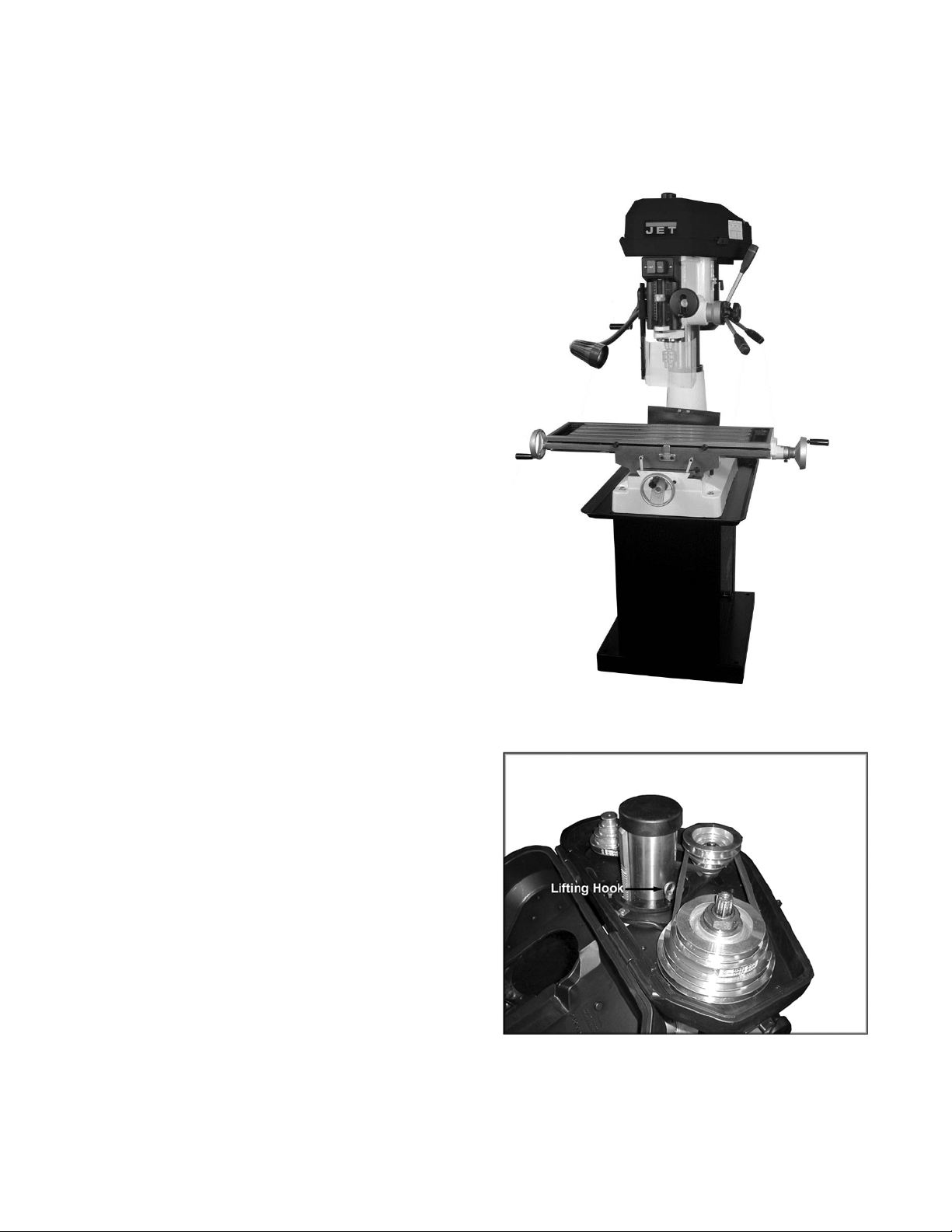
3. JMD-18/18PFN only: Open the belt cover
and thread the lifti ng hook into the head.
4. Carefully lift t he mill/ drill with properly rat ed
equipment to a sturdy stand or work bench.
(Use the lifting hook on the JMD-18/18PFN.
On the JMD-15, place straps beneath the
head, next to the colum n.
5. Remove the lifting hook (JMD-18/18PFN).
6
(JMD-18 shown with optional CS-18 stand)
(JMD-18/18PFN only)
Page 7
7.0 Assembly
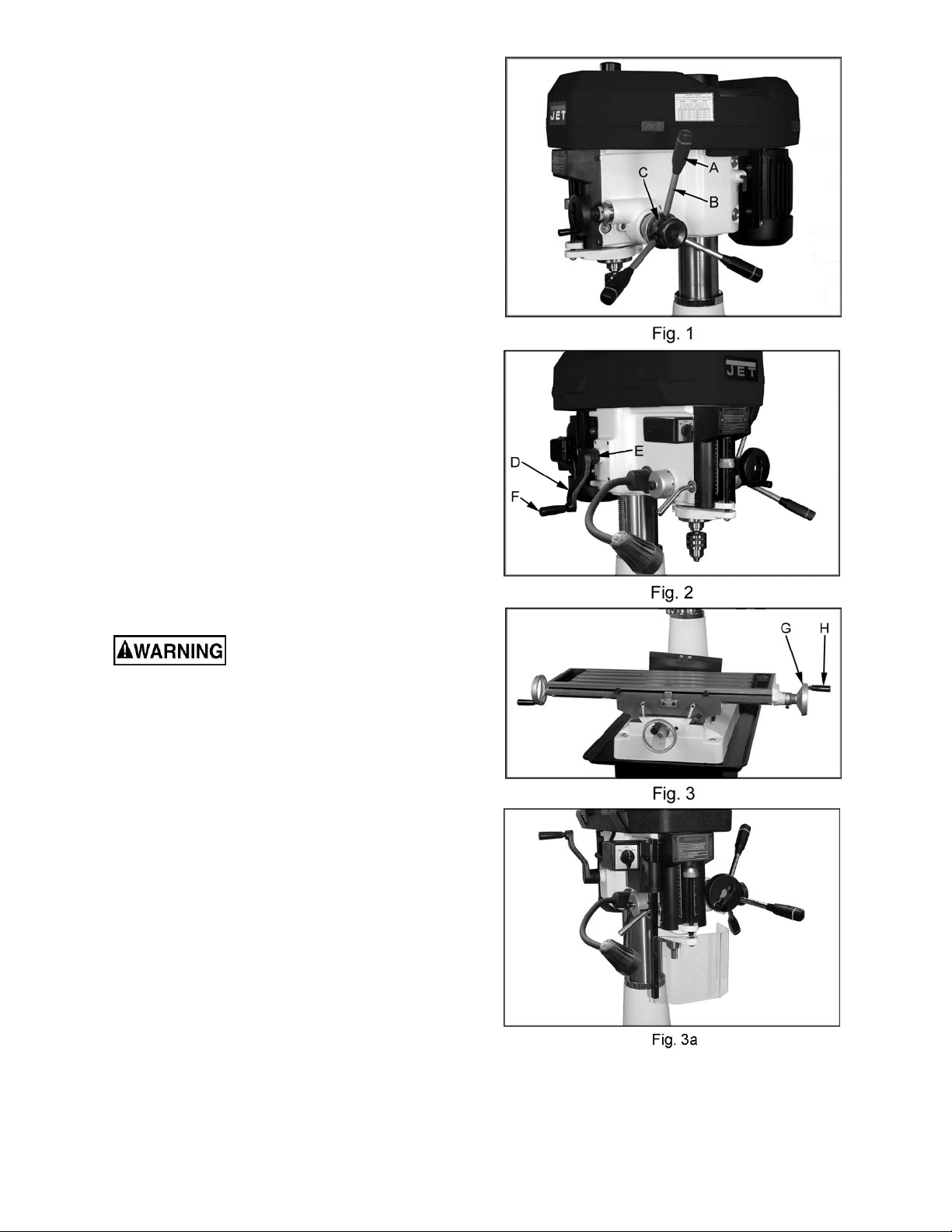
1. Screw rubber handles (A, Fig. 1) onto
handle rod (B, Fig. 1). Sc rew handle rod int o
downfeed hub (C, Fig. 1) and tighten. Flat
spot on rod accommodates a combination or
adjustable wrench. Note: Handle shaf ts are
already instal led into hub on JMD-18PFN.
2. Repeat for other two rod assemblies.
3. Slide crank ( D, Fig. 2) onto shaft and t ight en
set screw (E, Fig. 2). Be sure set screw
seats on flat part of shaft .
4. Thread handle (F, Fig. 2) into crank and
tighten.
5. Slide handwheel (G, Fig. 3) onto table
handwheel shaft and tighten set screw.
Insert handle (H, Fig. 3) into handwheel and
tighten.
6. Repeat for two remaining table hand wheels.
7. Install spindle guard assembly (Figur e 3a).
8.0 Installation
Machine is heavy! Use an
appropriate lifting device and use extreme
caution when moving th e machi ne to i ts fin al
location. Failure to comply may cause
serious injury.
1. The location for the mill/drill should be well
lit, dry, and hav e room enough to allow the
head to rotate 360°.
2. Before bolting the mill/drill to a bench or
stand, the unit must be level in both
directions. P lace a l evel on the t able in both
directions.
3. If the table is not level, shim under the low
corner(s) until level. Tighten the fastening
bolts. Check for level again. Adjust as
necessary until the mill/drill is level after t he
fastening hardware has been tightened.
7
Page 8
9.0 Lubrication
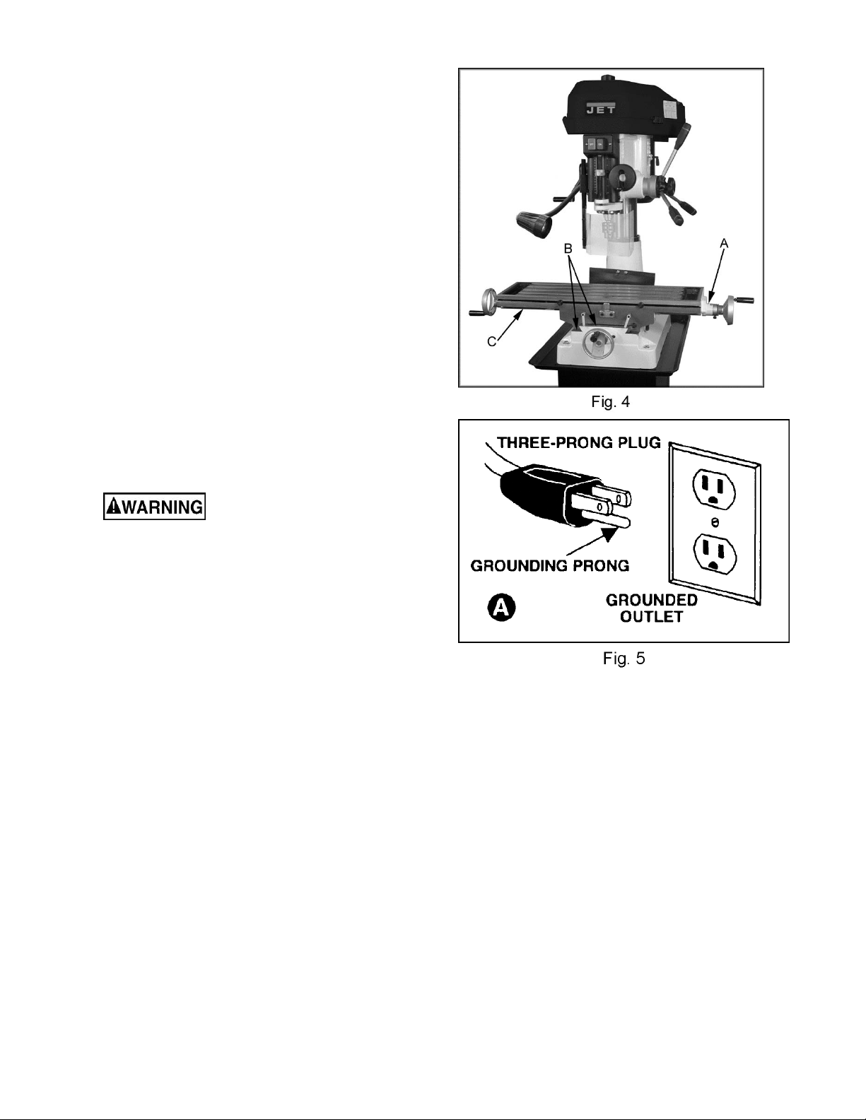
Lubricate ball oilers (A, Fig. 4) by the X/Y-axis
hand wheels, the oiler at the raising/lowering
crank handle, and the oiler on front of the bed
once daily with M obil DTE® Oil Heavy Medium.
Lubricate the ways (B, Fig. 4) once daily with
Mobil DTE® Oi l Heavy Medium.
If the head does not rise or lower smoothly,
apply Mobili th AW2 to the r ac k , and Mobil DTE®
Oil Heavy Me dium to the colum n.
If the feed handl es do not turn smoot hly, apply
Mobilith AW 2 to the cross and longi tudinal lead
screws (C, Fig. 4). Access the cross lead screw
by moving the table forward and removing the
way cov er.
The spindle bearings are permanently sealed
and require no l ubri c ation.
10.0 Electrical Connections
A qualified electrici an mu st
make all electrical connections. Failu re to
comply may cause seriou s injury.
Before maki ng any electrical connections, make
sure the power source available is compatible
with the machine. Also, turn the machine OFF
using the buttons or switch at the front of the
machine befor e c onnec ting to the power source.
The JMD Mill/Drills are rated at 115/230V and
come from the factory prewired at 115V. The
mill/drill comes with a plug designed for use on a
circuit with an outlet that looks like the one in
Fig. 5, and has a gr ounding prong as illustrat ed
in Fig. 5.
To switch the Mill/ Dri ll to 230V operation:
1. Disconnect machine from power source.
2. Remove junc tion box cover on the motor.
3. Change the wires according to t he diagram
on the inside of the juncti on box cover, and
reinstall junc tion box cover.
4. Replace thermal relay with one rated for
230V operation (see parts list).
5. Change power plug to one rated 230V, or
hard wire the power cord.
Make sure the mill/drill is properly grounded.
8
Page 9
11.0 Controls
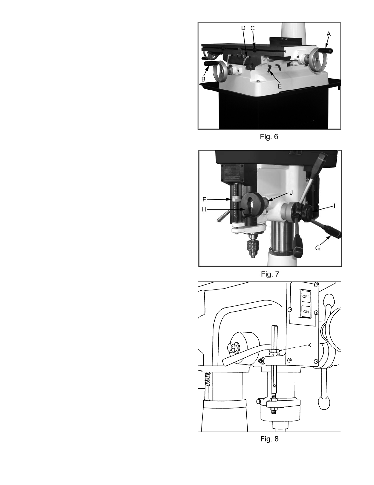
Longitudinal Han d Wh eel s: (X-axis) (A, Fig. 6)
Located on either side of the table. Moves table
side to side.
Cross Feed Hand Wheel: (Y-axis) (B, Fig. 6)
Located on the front of the base. Moves table
toward, or away from the colum n.
Adjustable Table Stops: (C, Fig. 6)
Located on table front. Adjust to stop table at
any setting along the longitudinal axis.
Table Locks: ( D & E, Fig. 6)
Longitudinal table locks are located on front of
the table. Cross-f eed table locks are located on
the right si de under the table. Tur n clockwise to
lock.
Depth Stop:
JMD-15: (K, Fig. 8) loc ated on the left side. Set
nuts for desired depth stop.
JMD-18: ( F, F ig. 7) l ocat ed in the front. Push i n
the button on the front of the quick adjust stop
and move to desired position.
JMD-18PFN: Set the depth stop on the power
down feed assembly to desired depth for
repetitiv e drilli ng to the sam e depth, see “P ower
Feed Operation” on page 12.
Downfeed Handles: (G, Fig. 7)
Located on the right side of the head casting.
Counter-clockwise movement advances the quill
toward the table. Return spring retracts the
handles. Note: the knob (I, Fig. 7) must be loose
for the downfeed handles to work.
Fine Feed Hand Wheel: (H, Fig. 7)
Located on the front of the head casting. To
activate, ti ghten the knob (I Fig. 7) and turn the
power feed speed range dial ( J , Fig. 7) to zero.
9
Page 10
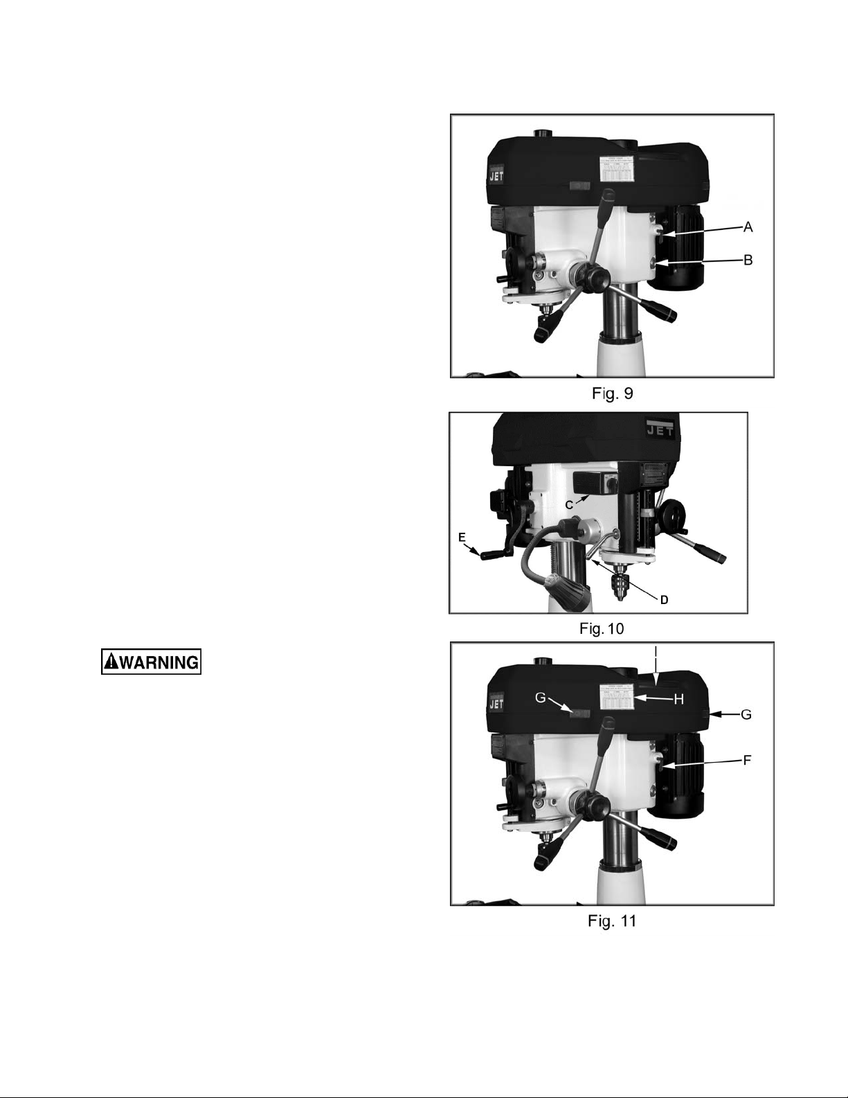
Motor Mount Lock Lever: (A, Fig. 9)
Located on the right side of the head casting.
Locks and unlocks the motor mounting plate
enabling the user to tension v-belts.
Head Pivot Lock: (B, Fig. 9)
Located on the right rear of the head casting.
Loosen two hex nuts to rotate the head 360°.
Tighten two hex nuts to lock the head in
position.
On-Off Switch: (C, Fig. 10)
Turns spindle on and off, and changes spindle
direction. Allow the spindle to come to a stop
before rev er si ng rotation.
Quill Lock Handle: (D, Fig. 10)
Located on the front left of the head casting.
Turn clockwise to lock the quill in the desired
position. Turn c ounter-clockwise to release.
Head Elevating Cran k Hand le: (E, Fig. 10)
Located at left rear of head casting. Loosen
head pivot lock nuts (B, Fig. 9) and turn handle
clockwise to raise head on the column and
counter-clockwise to lower head.
3. Release two latches (G, Fig. 11) on belt
cover and slide pulley guard open (I, Fig.
11).
This machine is designed
and intended for use by properly trained and
experienced personnel only. If you are not
familiar with the proper and safe use of
mill/drills, do not use this machine until
proper training and knowledge have been
obtained. Failure to comply may cause
serious injury.
12.0 Adjustments
12.1 Changing Spindle Speeds
1. Disconnect the machine from the power
source , un plug.
2. Loosen the motor mount lock lever (F, Fig,
11) and pull the motor toward the head
casting to release tensi on on the v-belts.
10
Page 11

4. Arrange the v-belts (A, Fig. 12) on the
pulleys (B, Fig. 12) for the desired speed
according to t he speed chart (H, Fi g. 11) on
the belt cover.
5. Tension the v-belts by pushing the motor
away from the head c asting and locki ng the
motor m ount lock lever (F, Fig. 11). Note:
Proper tension i s achieved when the slack in
the belt is taken up and the belt does not sl ip
during operation of the mill/drill.
12.2 Arbor Replacement
1. Disconnect machine from the power
source, unplug.
2. Release two latc hes (G, Fig. 11) on the belt
cover and slide the pulley guard open (I , Fig.
11).
3. Hold the spindle pulley (B, Fig. 12) t o keep
the pulley from moving while loosening the
drawbar (C, Fig. 12) with a wrench.
4. Loosen the drawbar approximately three to
four full turns.
5. Tap the drawbar head with a rubber mallet
to dislodge the ar bor.
Do not loosen the drawbar
more than three or four turns before hitting
with a rubber mall et. Damage to the drawbar
threads may occur.
6. Grasp the arbor with one hand while
loosening the drawbar with the other.
Continue to loosen the drawbar until the
arbor can be withdrawn from the spindle.
Wipe out the spindle with a clean dry rag.
7. W ipe down the new arbor with a clean dry
rag and place the arbor into the spindle.
Thread the drawbar int o the arbor. Tight en
the drawbar with a wrench whil e holding on
to the spindle pulley .
Use cautio n when tightening
drawbar. Do not allow hand to get pinched
between pulley and belt. Failure to comply
may cause seriou s injury.
Note: For best results, all milling operations
should be done wit h the quill /spindl e as close to
the head assembly as possible. Lock spindle
and table in place before starting milling
operations.
11
Page 12

12.3 Gib Adjustment
After a period of time, movement of the table
over the ways will cause normal wear. To adjust
the gibs for this wear:
1. The hor izontal gib adjustm ent screw (A, Fig.
13) is found to the right on the table face.
The traverse gib adjustment screw (B, Fig.
13) is found on t he right side of the saddle
under the table.
2. Turn each screw slightly clockwise to
tighten. Turn the table hand wheels and
check the tension.
3. Re-adjust as requi r ed.
12.4 Power Feed Operation (JMD-18PFN
only)
Make all pow er feed settings
with power t o the mach ine tu rned o ff. Failure
to comply may cause damage to the
machine.
1. Set the power feed speed range dial ( C , Fig.
2. Set the depth stop t o the desired setting by
3. Start the mill/drill and pull one of two
4. Once the downfeed has reached the depth
5. To stop the f eed bef ore the cycle has ended
14) to the desired rate.
lowering the quill to the desired depth and
holding i n plac e. Turn t he coll ar (D, Fig. 14)
counter-clockwise until zero is indicat ed and
then tighten the loc k handl e ( E, Fig. 14)
handles (F, Fig. 14) away from the col umn
to start the power downfeed.
stop, the trip will release and the spindl e wil l
retract.
or to disengage the fine feed (G, Fig. 14),
press one of two handles toward the
column.
3. Rotate the spring c ap cl ockwise to decr ease
spring tension. Rotate the spring cap
counter-clockwise to increase spring
tension.
12.5 Adjusting Spindle Return Spring
The spindle return comes pre-set from the
factory and should not need any adjustment.
1. You do not want to r emove the spring cap
(H, Fig. 15).
2. Loosen knob (I, Fig. 15) just enough to
rotate spring cap past t he notch ( J, Fig. 15).
12
Page 13

13.0 Replacement Parts
13.1.1 JMD-15 Head Assembly – Exploded View
13
Page 14

13.1.2 JMD-15 Head Assembly – Parts List
Index No. Part No. Description Size Qty
1 ............... JMD15-001 ..............Drawbar ................................................................................................ 1
2 ............... JMD15-002A ............Spindle Lock Nut ................................................................................... 1
3 ............... JMD15-003 ..............Spind le P u l le y........................................................................................ 1
5 ............... JMD15-005 ..............Outer Bearing Plate ............................................................................... 1
6 ............... JMD15-006A ............Spindle Taper Sleeve ............................................................................ 1
7 ............... BB-6007ZZ ..............Ball Bearing ........................................................6007ZZ....................... 2
8 ............... JMD15-008 ..............Bearing Spacer ...................................................................................... 1
9 ............... JMD15-009 ..............C-Ring ................................................................................................... 1
10 ............. JMD18-010 ..............C-Ring ................................................................................................... 1
11 ............. JMD15-011 ..............Head ..................................................................................................... 1
12 ............. JMD15-012 ..............Rubber Flange....................................................................................... 1
13 ............. JMD15-013 ..............Feed Base ............................................................................................. 1
14 ............. JMD15-014 ..............Lock Nut ................................................................................................ 2
15 ............. BB-30205 .................Taper Roller Bearing...........................................30205 ......................... 1
16 ............. JMD15-016 ..............Rack Sleeve .......................................................................................... 1
17 ............. JMD15-017 ..............Spindle Sh aft ......................................................................................... 1
18 ............. BB-30206 .................Taper Roller Bearing...........................................30206 ......................... 1
19 ............. JMD15-019 ..............Bearing Cap .......................................................................................... 1
20 ............. JMD15-020 ..............Cutting Arbor ......................................................................................... 1
21 ............. JMD15-021 ..............Chuck Arbor .......................................................R8 x JT6 ..................... 1
22 ............. JMD18-022 ..............Handle................................................................................................... 1
23 ............. JMD15-023 ..............Retainer Ring ........................................................................................ 1
24 ............. JMD15-024 ..............Lock Handle (Seri al #14022982 and lower) ............................................ 1
................. JMD15- 024N
25 ............. JMD15-025 ..............Fixed Collar ........................................................................................... 1
26 ............. JMD15-026 ..............Fixed Collar Thread ............................................................................... 1
27 ............. JMD15-027 ..............Screw Key ..........................................................3/8 .............................. 1
35 ............. JMD18-035 ..............Bearing Spacer ...................................................................................... 1
38 ............. JMD18-038 ..............Lock Bolt w/ Knob .................................................................................. 1
39 ............. JMD18-039 ..............Handle Rod ........................................................................................... 3
40 ............. JMD18-040 ..............Knob ..................................................................................................... 3
42 ............. JMD18-042 ..............Feed Handle Wheel ............................................................................... 1
44 ............. JMD18-044 ..............Micro Adjusting Indicator........................................................................ 1
45 ............. JMD18-045 ..............Worm Cover .......................................................................................... 1
46 ............. BB-6202Z ................Ball Bearing ........................................................6202Z ......................... 2
47 ............. JMD18-047 ..............Worm Sh aft ........................................................................................... 1
51 ............. JMD18-051 ..............Leaf Screw ............................................................................................ 1
52 ............. JMD15-052 ..............Head Lock Bolt ...................................................1/2"x7” ........................ 2
54 ............. JMD15-054 ..............Graduated Rod and Dial Assembly ........................................................ 1
55 ............. JMD15-054 ..............Depth Scale ........................................................................................... 1
57 ............ JMD15-057 ..............Name Pla te (Serial #14022982 and lower) ............................................. 1
................. JMD15- 057A ............Name Pla te (Serial #14022983 and higher)............................................ 1
58 ............. JMD15-058 ..............Head Handle ......................................................................................... 1
59 ............. JMD15-059 ..............Worm Sh aft ........................................................................................... 1
60 ............. JMD15-060 ..............Worm Gea r ............................................................................................ 1
61 ............. JMD15-061 ..............Shaft ..................................................................................................... 1
62 ............. JMD18-062 ..............Compre ssion Spring .............................................................................. 1
63 ............. JMD15-063 ..............Pin......................................................................................................... 1
66 ............. JMD15-066 ..............Motor Mount .......................................................................................... 1
67 ............. JMD15-067 ..............Motor (Serial #06041349 and lower) ...................1HP, 1Ph .................... 1
................. JMD15- 067N ............Motor (Serial #06041350 and higher) ..................1HP, 1Ph .................... 1
68 ............. JMD15-067A ............Capacitor (not shown).........................................150MF, 250VAC ......... 1
69 ............. JMD15-069P ............Belt Cover ............................................................................................. 1
69-1 .......... JMD15-069P1 ..........Upper Belt Cover Cap............................................................................ 1
69-2 .......... JMD15-069P2 ..........Upper Belt Cover Plate .......................................................................... 1
70 ............. JMD15-070 ..............Motor Pulley (Serial #06041349 and lower) ............................................ 1
................. JMD15- 070N ............Motor Pulley (Serial #06041350 and higher) .......................................... 1
............Lock Handle (S erial #14022983 and higher) .......................................... 1
14
Page 15

Index No. Part No. Description Size Qty
71 ............. VB-A30 ....................V-Belt .................................................................A30 ............................ 1
72 ............. BB-6204Z ................Ball Bearing ........................................................6204Z ......................... 2
73 ............. JMD15-073 ..............Inter Pulley ............................................................................................ 1
74 ............. VB-A38 ....................V-Belt .................................................................A38 ............................ 1
75 ............. JMD15-075P ............Inter Pulley Shaft ................................................................................... 1
76 ............. JMD15-076P ............Speed Change Inter Pulley Base ........................................................... 1
79 ............. JMD18-079 ..............Rubber Collar ........................................................................................ 1
81 ............. JMD18-122 ..............Switch Box ............................................................................................ 1
82 ............. JMD18-123 ..............Cross Round Head Screw ..................................3/16”x3/8 .................... 2
83 ............. JMD18-124 ..............Cable setting nut ................................................PG13.5 ....................... 2
84 ............. JMD18-121-1 ...........F/R Switch ............................................................................................. 1
85 ............. JMD18-085 ..............Screw w/ Plumb Knob............................................................................ 1
86 ............. JMD15-086 ..............Cutter .................................................................................................... 1
................. JMD15- 086A ............Cutter Insert (not shown) ....................................................................... 4
87 ............. JMD15-087 ..............Drill Chuck ............................................................................................. 1
87A .......... JMD15-087A ............Chuck Key ............................................................................................. 1
90 ............. JMD15-090 ..............Self Tapping Screw ............................................................................... 2
91-A ......... JMD18-116 ..............Lamp Assembly (includes 91~94)(Serial #14022983 and higher ) ........... 1
91 ............. JMD18-116-1 ...........Lamp ..................................................................................................... 1
92 ............. JMD15-092 ..............Cross Round Head Screw ..................................M4x35L ...................... 2
93 ............. JMD15-093. .............Working Lamp Base .............................................................................. 1
94 ............. JMD15-094 ..............Hex. Socket Head Screw ....................................M6x12L ...................... 2
103 ........... JMD18-103 ..............Spring Cover ......................................................................................... 1
104 ........... JMD18-104 ..............Spring.................................................................................................... 1
105 ........... JMD18-105 ..............Spring Base ........................................................................................... 1
106 ........... JMD15-106 ..............Pinion Shaft ........................................................................................... 1
107 ........... JMD18-107 ..............Worm Gear ............................................................................................ 1
108 ........... JMD18-108 ..............Gear Housing ........................................................................................ 1
110 ........... JMD18-110 ..............Hub ....................................................................................................... 1
115 ........... JMD18-115 ..............Spring.................................................................................................... 1
122 ........... JMD18-077 ..............Clip Plate ............................................................................................... 1
131 ........... TS-0813032 .............Pan Head Screw ................................................1/4"x1/2” ..................... 4
132 ........... TS-0680021 .............Washer...............................................................1/4" ............................ 4
133 ........... JMD18-133 ..............Round Head Screw ............................................1/4"x3/8” ..................... 3
134 ........... TS-0050091 .............Hex Head Bolt ....................................................1/4"x2” ........................ 1
135 ........... TS-0561011 .............Hex Nut ..............................................................1/4" ............................ 1
136 ........... TS-0561051 .............Hex Nut ..............................................................1/2" ............................ 2
137 ........... JMD15-137 ..............Lock Wash e r ......................................................................................... 1
138 ........... JMD15-138 ..............Rivet ...................................................................................................... 2
139 ........... JMD18-139 ..............Round Head Screw ............................................3/16”x3/4” ................... 3
140 ........... JMD18-140 ..............Spring Pin...........................................................3x12" .......................... 2
141 ........... TS-0561031 .............Hex Nut ..............................................................3/8 .............................. 3
142 ........... JMD18-142 ..............Key.....................................................................7x7x20 ....................... 1
143 ........... TS-0208041 .............Hex Socket Cap S cr e w .......................................5/16”x3/4” ................... 2
144 ........... TS-0680021 .............Washer...............................................................1/4" ............................ 1
145 ........... TS-0270021 .............Set Screw ...........................................................5/16”x5/16” ................. 3
146 ........... TS-0267031 .............Set Screw ...........................................................1/4"x5/16” ................... 1
147 ........... JMD18-147 ..............Round Head Screw ............................................3/16”x1/2” ................... 2
148 ........... JMD18-148 ..............C-Retainer Ring ..................................................................................... 1
150 ........... TS-0561051 .............Hex Nut ..............................................................1/2" ............................ 2
151 ........... TS-0680061 .............Washer...............................................................1/2" ............................ 2
152 ........... JMD15-152 ..............Round Head Screw ............................................M6x1.25 ..................... 6
153 ........... TS-0271061 .............Set Screw ...........................................................3/8”x5/8” ..................... 1
154 ........... TS-0561071 .............Hex Nut ..............................................................5/8”............................. 2
155 ........... TS-0680031 .............Washer...............................................................5/16” ........................... 8
156 ........... TS-0051051 .............Hex Head Bolt
157 ........... TS-0060051 .............Hex Head Bolt ....................................................3/8”x1/2” ..................... 2
158 ........... TS-0561021 .............Hex Nut ..............................................................5/16” ........................... 4
....................................................5/16”x1” ...................... 4
15
Page 16

Index No. Part No. Description Size Qty
159 ........... JMD18-159 ..............Key (Serial #06041349 and lower) ......................7x7x40 ....................... 1
................. JMD18- 159N ............Key (Serial #06041350 and higher) .....................6x6x45 ....................... 1
160 ........... TS-0051071 .............Hex Head Bolt ....................................................5/16”x1-1/2” ................ 1
161 ........... TS-0680031 .............Washer...............................................................5/16” ........................... 2
187 ........... TS-0680021 .............Washer...............................................................1/4" ............................ 2
188 ........... JMD18-188 ..............Pan Head Screw ................................................3/16”x3/8” ................... 1
208 ........... TS-0561031 .............Hex Nut ..............................................................3/8”............................. 1
209 ........... JMD18-119 ..............Lifting Hook ........................................................5/16 ”x50mm ............... 1
210 ........... TS-0570021 .............Hex Nut ..............................................................5/16”-18 ...................... 1
211-A ....... JMD 15-211A ............Chuck Guard Assembly ......................................................................... 1
211-1 ........ JMD15 -211-1... ........Chuck Guard & Support Rod ................................................................. 1
211-3 ........ TS-2361051 .............Spring Wash er....................................................M5 .............................. 4
211-4 ........ TS-1502021 .............Socket Head Cap Screw .....................................M5x10 ........................ 2
211-5 ........ JMD15 -211-5 ...........Chuck Guard Bracket ............................................................................ 1
211-6 ........ JMD18 -125-5 ...........Rotary Supporting Base ........................................................................ 1
211-7 ........ JMD18 -125-6 ...........Hex. Socket Head Screw ....................................M5x15L ...................... 2
211-8 ........ JMD15 -211-8 ...........S prin g Was her....................................................M6 .............................. 2
211-9 ........ JMD15 -211-9 ...........Hex. Socket Head Screw ....................................M6x15L ..................... 2
211-10 ...... JMD18-125-7 ...........Hex. Socket Headless Screw ..............................M5x10L ...................... 1
................. JMD15- SC ...............Speed Chart Label (not shown) ............................................................. 1
................. JMD15- JL ................Jet Label (not shown) ............................................................................ 1
................. JMD15- ID ................I.D. Label (not shown) ............................................................................ 1
................. JMD15- AP ...............Access ory Package (not shown) * .......................................................... 1
................. JMD15- 303 ..............Thermal Relay (not shown) .................................18A,115V ................... 1
* Contents of the Accessory Package ( JM D 15- AP):
................. JMD15-020 ..............Cutter Arbor ........................................................................................... 1
................. JMD15- 039 ..............Handle Rod ........................................................................................... 3
................. JMD15- 040 ..............Knob ..................................................................................................... 3
................. JMD15- 087 ..............Drill Chuck ............................................................................................. 1
................. JMD15- 087A ............Chuck Key ............................................................................................. 1
................. JMD15- 086 ..............Cu tter .................................................................................................... 1
................. 365534 ....................Angle Vise ............................................................................................. 1
................. JMD15- 022 ..............Handle................................................................................................... 4
................. JMD15- 201 ..............Wheel .................................................................................................... 3
................. JMD15- 058 ..............Handle Crank ........................................................................................ 1
................. TS-152704 ...............Hex Wrench .......................................................3mm ........................... 1
................. TS-152705 ...............Hex Wrench .......................................................4mm ........................... 1
................. TS-152706 ...............Hex Wrench .......................................................5mm ........................... 1
................. JMD15- 381 ..............Wash er.................................................................................................. 1
................. JMD15- 380 ..............He x Bo l t ................................................................................................ 1
................. JMD15- 377 ..............He x Bo l t ................................................................................................ 2
................. JMD15- 378 ..............Hex Nut ................................................................................................. 2
................. JMD15- 379 ..............Wash er.................................................................................................. 2
................. MP-007 ....................Touch Up Paint ...................................................................................... 1
16
Page 17
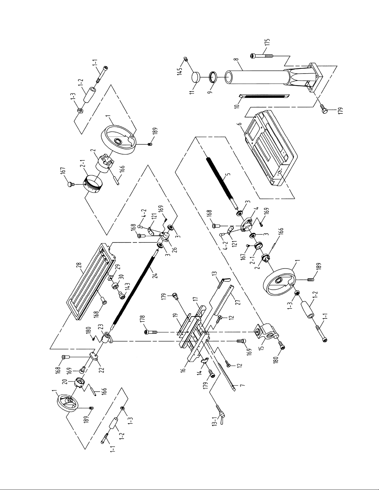
13.2.1 JMD-15 Table, Base, and Column Assembly – Exploded View
17
Page 18

13.2.2 JMD-15 Table, Base, and Column Assembly – Parts List
Index No. Part No. Description Size Qty
1 ............... JMD18-201 ..............Table Hand Wheel ................................................................................. 3
1-1............ JMD 18-201-1 ...........Bolt........................................................................................................ 3
1-2............ JMD 18-201-2 ...........Handle................................................................................................... 3
1-3............ JMD 18-201-3 ...........Nut ........................................................................................................ 3
2 ............... JMD18-202 ..............Dial Clutch ............................................................................................. 2
2-1............ JMD 18-202-1 ...........Graduated Dial ...................................................................................... 2
3 ............... BB-51103 .................Thrust Bearing ....................................................51103 ......................... 4
4 ............... JMD15-204 ..............Square Flange ....................................................................................... 1
4-2............ JMD 18-204-2 ...........Rivet ...................................................................................................... 4
5 ............... JMD15-205 ..............Table Screw .......................................................................................... 1
6 ............... JMD15-206 ..............Base ...................................................................................................... 1
7 ............... JMD15-207 ..............Gib Strip ................................................................................................ 1
8 ............... JMD15-208 ..............Column Base ......................................................................................... 1
9 ............... JMD15-209 ..............Column Flange Ring .............................................................................. 1
10 ............. JMD15-210 ..............Rack ...................................................................................................... 1
11 ............. JMD15-211 ..............Column Cap .......................................................................................... 1
12 ............. JMD15-212 ..............Adjustment Screw.................................................................................. 2
13 ............. JMD18-213 ..............Leaf Screw ............................................................................................ 2
13-1 .......... JMD18-213 ..............Locking Handle ...................................................................................... 2
14 ............. JMD18-214 ..............Block ..................................................................................................... 1
15 ............. JMD18-215 ..............Table Base Nut ...................................................................................... 1
16 ............. JMD15-216 ..............Center Base .......................................................................................... 1
17 ............. JMD15-217 ..............Way Cover ............................................................................................ 1
19 ............. JMD18-219
20 ............. JMD18-220 ..............Table Clutch .......................................................................................... 1
22 ............. JMD15-222 ..............Left Flange ............................................................................................ 1
23 ............. JMD18-223 ..............Table Nut .............................................................................................. 1
24 ............. JMD15-224 ..............Table Screw .......................................................................................... 1
26 ............. JMD15-226 ..............Right Flange .......................................................................................... 1
27 ............. JMD15-227 ..............Gib Strip ................................................................................................ 1
28 ............. JMD15-228 ..............Table ..................................................................................................... 1
29 ............. JMD18-229 ..............Block ..................................................................................................... 2
30 ............. JMD18-230 ..............Ring ...................................................................................................... 2
121 ........... JMD15-121 ..............Indicator Plate ....................................................................................... 2
143 ........... TS-0207021 .............Hex Socket Cap S cr e w .......................................1/4"x1/2” ..................... 2
145 ........... TS-0270021 .............Set Screw ...........................................................5/16”x5/16” ................. 1
166 ........... JMD18-366 ..............Spring Pin.............................................................................................. 3
167 ........... JMD18-367 ..............Zero Indicator w/ Screw ......................................1/4"x3/8” ..................... 2
168 ........... JMD18-368 ..............Oil Ball................................................................................................... 5
169 ........... TS-0209031 .............Hex Socket Cap S cr e w .......................................3/8”x3/4” ..................... 8
175 ........... TS-0061071 .............Hex Head Bolt ....................................................7/16”x2” ...................... 4
178 ........... TS-0208111 .............Hex Cap Bolt ......................................................5/16 ”x2-1/4” ................ 1
179 ........... TS-0051011 .............Hex Cap Bolt ......................................................5/16 ”x1/2” ................... 6
180 ........... TS-1502041 .............Hex Socket Cap S cr e w .......................................M5x16 ........................ 2
189 ........... TS-0267041 .............Set Screw ...........................................................1/4"x3/8” ..................... 3
..............Bracket Plate ......................................................................................... 1
18
Page 19

13.3.1 JMD-18/18PFN Head Assembly – Exploded View
19
Page 20

13.3.2 JMD-18/18PFN Head Assembly – Parts List
Index No. Part No. Description Size Qty
1 ............... JMD18N-001 ............Head Body ............................................................................................ 1
2 ............... JMD18-001 ..............Draw bar .............................................................R8 .............................. 1
3 ............... JMD18-002A ............Spindle Lock Nut ................................................................................... 1
4 ............... JMD18-003A ............Spindle P u l ley........................................................................................ 1
5 ............... JMD18-005 ..............Outer Bearing Plate ............................................105x66 ....................... 1
6 ............... JMD18-133 ..............Round Head Screw ............................................1/4”x3/8” ..................... 3
7A ............ JMD1 8-006A ............Spind le Taper Sleeve Assembly ............................................................ 1
7-1............ JMD 18-006 ..............Spindle Taper Sleeve ............................................................................ 1
7-2............ BB-6009ZZ ..............Ball Bearing ........................................................6009ZZ....................... 2
7-3............ JMD 18-008 ..............Spacer................................................................7 4x68 ......................... 1
7-4............ JMD 18-023 ..............Fixed Ring ..........................................................2x4 ............................. 1
8 ............... JMD18-009 ..............C-Re taining Ring ................................................3 x80 ........................... 1
9 ............... JMD18-012 ..............Rubber Flange....................................................................................... 1
10 ............. JMD18N-010 ............Feed Base ............................................................................................. 1
11A .......... JMD18-014A ............Rack Sleeve Set .................................................................................... 1
11-1 .......... JMD18-014 ..............Lock Nut ................................................................................................ 2
11-2 .......... JMD18-137 ..............Lock Washer ...................................................... 30206 ......................... 1
11-3 .......... BB-30206 .................Taper Roller Bearing.............................................................................. 1
11-4 .......... JMD18-016 ..............Rack Sleeve .......................................................R8 .............................. 1
11-5 .......... BB-30207 .................Taper Roller Bearing...........................................30207 ......................... 1
11-6 .......... JMD18-017 ..............Spindle Shaft ......................................................R8 .............................. 1
11-7 .......... JMD18-019 ..............Bearin g Cap .......................................................R8 .............................. 1
13 ............. JMD18-021 ..............Chuck Arbor .......................................................R8 7/16” ..................... 1
14 ............. JMD18-020 ..............Cutter Arbor ........................................................25.4 7/16” ................... 1
15A .......... JMD18N-015A .........Graduated Rod Assembly ...................................................................... 1
15-1 .......... JM D 1 8 N -1 5 - 1 ..........D e p th Sca le S tu d................................................................................... 1
15-2 .......... JMD18N-15-2 ..........Adjustable Stop ..................................................................................... 1
15-3 .......... JMD18N-15-3 ..........Spring.................................................................................................... 1
15-4 .......... JMD18N-15-4 ..........Push Button ........................................................................................... 1
15-5 .......... JM D 1 8 N -1 5 - 5 ..........H e x Soc ke t Ca p S cr e w .......................................M5x10 ........................ 1
15-6 .......... JMD18N-15-6 ..........Washer...............................................................3/8” ............................. 1
15-7 .......... JMD18N-15-7 ..........Hex Nut ..............................................................3 /8”............................. 1
17 ............. TS-0050091 .............Hex Head Screw ................................................1/4”x2” ........................ 1
18 ............. TS-0561011 .............Hex Nut ..............................................................1/4”............................. 1
20 ............. JMD18-106 ..............Pinion Shaft ........................................................................................... 1
21 ............. JMD18-188 ..............Flat Cross Head Screw .......................................3/16”x3/8” ................... 1
22 ............. JMD18-142 ..............Key.....................................................................7x7 x20mm.................. 1
23A .......... JMD18N-023A .........Gear Housing Assembly ........................................................................ 1
23-1 .......... JMD18N-023 ............Gear Housing ........................................................................................ 1
23-2 .......... JMD18-047 ..............Worm Sh aft ........................................................................................... 1
23-3 .......... BB-6202Z ................Ball Bearing ........................................................6202ZZ....................... 2
23-4 .......... JMD18-148 ..............C-ring .................................................................15 ............................... 1
23-5 .......... JMD18-035 ..............Bearing Spacer ...................................................34x27.5 ...................... 1
24 ............. TS-0208021 .............Hex Socke t Ca p Sc re w .......................................5/16”x1/2” ................... 2
25 ............. JMD18-107 ..............Worm Gea r ............................................................................................ 1
26 ............. JMD18-115 ..............Spring .................................................................................................... 1
27 ............. JMD18-110 ..............Hub ....................................................................................................... 1
28 ............. JMD18-038 ..............Knob ..................................................................................................... 1
29 ............. JMD18-039
30 ............. JMD18N-030 ............Knob ..................................................................................................... 3
31 ............. JMD18-045 ..............Flange ................................................................................................... 1
32 ............. JMD18-047 ..............Round Head Screw ............................................3/16”x3/8” ................... 2
33 ............. JMD18N-033 ............Micro Adjusting Indicator........................................................................ 1
33-1 .......... TS-0267021 .............Set Screw ...........................................................1/4”x1/4” ..................... 1
35 ............. JMD18N-035A .........Feed Handle W heel A ssem bly ............................................................... 1
35-1 .......... JMD18N-035-1.........Set Screw ...........................................................M8x10 ........................ 1
..............Handle Rod ........................................................................................... 3
20
Page 21

Index No. Part No. Description Size Qty
37 ............. JMD18-105 ..............Spring Base ........................................................................................... 1
37-1 .......... JMD18-140 ..............Spring Pin.............................................................................................. 2
39 ............. JMD18-139 ..............Round Head Screw ............................................3/16”x3/4” ................... 3
40A .......... JMD18-103A ............Spring Cover Assembly ......................................................................... 1
40-1 .......... JMD18-103 ..............Spring Cover ......................................................................................... 1
40-2 .......... JMD18-104 ..............Spring .................................................................................................... 1
41 ............. JMD18-187 ..............Washe r ..............................................................1/4”x1” ........................ 1
42 ............. TS-0680021 .............Washer ...............................................................1/4”............................. 1
43 ............. JMD18-187 ..............Lock Washer ......................................................1 /4 ” x1” ........................ 1
44 ............. JMD18-085 ..............Knob ..................................................................................................... 1
45 ............. JMD18-059 ..............Worm Sh aft ........................................................................................... 1
46 ............. JMD18-114 ..............Bushing ................................................................................................. 1
47A .......... JMD18-101A ............Head Raise Bracket Assembly ............................................................... 1
47-1 .......... JMD18-101 ..............Head Raise Bracket ............................................................................... 1
47-2 .......... JMD18-060 ..............Worm Gea r ............................................................................................ 1
47-3 .......... JMD18-061 ..............Shaft ..................................................................9 /1 6 ” ........................... 1
47-4 .......... JMD18-154 ..............C-ring .................................................................S14 ............................ 2
48 ............. TS-0207061 .............Hex Socke t Ca p Sc re w .......................................1/4”x1” ........................ 4
49 ............. JMD18-058 ..............Head Handle ........................................................................................ 1
49-1 .......... TS-0271061 .............Set Screw ...........................................................3/8”x5/8” ..................... 1
51 ............. JMD18-022 ..............Handle................................................................................................... 1
51-1 .......... TS-0561031 .............Hex Nut ..............................................................3/8”............................. 1
52 ............. JMD18-026 ..............Fixed Collar (Thread) ............................................................................. 1
53 ............. JMD18-025 ..............Fixed Collar ........................................................................................... 1
54 ............. JMD18N-054
55 ............. JMD18-024 ..............Handle Rod ........................................................................................... 1
56 ............. JMD18-027 ..............Screw Key ..........................................................3/8”............................. 1
57 ............. TS-0561031 .............Hex Nut ..............................................................3/8”............................. 1
58 ............. JMD18-062 ..............Spring .................................................................................................... 1
59 ............. JMD18-063 ..............Pin......................................................................................................... 1
60 ............. JMD18-079 ..............Rubber Collar ........................................................................................ 1
61 ............. JMD18-052 ..............Bolt.....................................................................5/8”x6” ........................ 2
62 ............. TS-0680081 .............Washer ...............................................................5/8”............................. 2
63 ............. TS-0561071 .............Hex Nut ..............................................................5/8”............................. 2
64 ............. JMD18-050 ..............Lock Handle .......................................................................................... 1
65 ............. JMD18N-065 ............Knob ..................................................................................................... 1
66A .......... JMD18N-066A .........Front Cover Plate Assembly (serial no: previous to 11043083)............... 1
66A .......... JMD18N-066B .........Front Cover Plate Assembly (includes 66-1,66-4,66-5)
serial no: 11043083 and higher .......................................................... 1
66-1 .......... JMD18N-066-1.........Front Cover Plate .................................................................................. 1
66-4 .......... JMD18N-066-4.........Front Cover Plate .................................................................................. 1
66-5 .......... TS-1533032 .............Phillips Pan Head Machine Screw ......................M5 x10 ........................ 4
67 ............. JMD18N-067 ............Round Head Screw ............................................M6x12 ........................ 4
71 ............. JMD18-069 ..............Poly Bel t Cover ...................................................................................... 1
72 ............. JMD18-069A ............Pulley Cover .......................................................................................... 1
74 ............. JMD18-069-1 ...........Spindle Cover ........................................................................................ 1
75 ............. JMD18-069-3 ...........Screw .................................................................3mm ........................... 2
76 ............. TS-0680032 .............Flat Washe r ........................................................5/16” ........................... 4
77 ............. TS-0051011 .............Hex Head Bolt ....................................................5/16”x1/2” ................... 4
79 ............. JMD18-S C ...............Spindle Speed Chart.............................................................................. 1
80 ............. JMD18N-080 ............Pulley Base ........................................................................................... 1
81 ............. TS-
82 ............. TS-0680031 .............Washer...............................................................5/16” ........................... 2
83 ............. TS-0051071 .............Hex Head Bolt ....................................................5/16”x1-1/2” ................ 1
84A .......... JMD18-075A ............Inter Pulley Assembly ............................................................................ 1
84-1 .......... JMD18-075 ..............Inter Pulley Shaft ................................................................................... 1
84-2 .......... JMD18-073 ..............Inter Pulley ............................................................................................ 1
84-3 .......... BB-6204Z ................Ball Bearing ........................................................6204ZZ....................... 2
0561071 .............Hex Nut ..............................................................5/8”............................. 1
............Washer...............................................................1/2”x7/8” ..................... 1
21
Page 22

Index No. Part No. Description Size Qty
84-4 .......... JMD18-010 ..............C-ring .................................................................2x52 ........................... 1
85 ............. TS-0561071 .............Hex Nut ..............................................................5/8”............................. 1
86 ............. JMD18-070 ..............Motor Pulley (Serial #06013377 and lower) ............................................ 1
................. JMD18- 070N ............Motor Pulley (Serial #06013378 and higher) .......................................... 1
86-1 .......... TS-0270021 .............Set Screw ...........................................................5/16”x5/16” ................. 2
88 ............. VB-B33 ....................V-Belt .................................................................B33 ............................ 1
89 ............. VB-B42 ....................V-Belt .................................................................B42 ............................ 1
90 ............. JMD18-077 ..............Wire Relief Retainer .............................................................................. 1
91 ............. TS-0051011 .............Hex Head Screw ................................................5/16”x1/2” ................... 1
92 ............. JMD18-066 ..............Motor Mount Plate ................................................................................. 1
93 ............. JMD18-067 ..............Motor (Serial #06013377 and lower) ...................2HP, 1Ph, 230V Only.. 1
................. JMD18- 067N ............Motor (Serial #06013378 and higher) ..................2HP, 1Ph, 230V Only.. 1
................. JMD18- 067AN .........Motor (Serial #11053083 and higher) ..................2HP, 1PH, 115/230V .. 1
94 ............. TS-0680031 .............Flat Washe r ........................................................5/16” ........................... 8
95 ............. TS-0051051 .............Hex Head Bolt ....................................................5/16”x1” ...................... 4
96 ............. TS-0561021 .............Hex Nut ..............................................................5/16” ........................... 4
97 ............. TS-0061011 .............Hex Head Bolt ....................................................7/16”x3/4” ................... 2
98 ............. JMD18-159 ..............Key (Serial #06013377 and lower) ......................7x7x37mm.................. 1
................. JMD18- 159N ............Key (Serial #06013378 and higher) .....................8x7x45 mm.................. 1
113 ........... 561704 ....................Drill Chuck w/ Chuck Key....................................1/2” JT6 ...................... 1
114 ........... JMD18-086 ..............Milling Cutter Assembly ......................................25.4mm (3”) ................ 1
................. JMD18- 086A ............Cutter Insert .......................................................12x12mm ................... 4
115 ........... JMD18N-115 ............Power Cable .......................................................230V .......................... 1
116 ........... JMD18-
116-1 ........ JMD18 -116-1 ...........Lamp ..................................................................................................... 1
116-2 ........ JMD15 -092 ..............Cross Round Head Screw ..................................M4 x35L ...................... 2
116-3 ........ JMD15 -093 ..............Working Lamp Base .............................................................................. 1
116-4 ........ JMD15 -094 ..............Hex. Socket Head Screw ....................................M6x12L ...................... 2
117 ........... JMD18N-117 ............Motor Cable ........................................................................................... 1
119 ........... JMD18-119 ..............Lifting Hook ........................................................5/16 ”x50mm ............... 1
120 ........... TS-0570021 .............Hex Nut ..............................................................5/16”-18 ...................... 1
121 ........... JMD18-121-1 ...........F/R Switch ............................................................................................. 1
122 ........... JMD18-122 ..............Switch Box ............................................................................................ 1
123 ........... JMD18-123 ..............Cross Round Head Scre w ..................................3/16"-24UNCx3/8"L .... 2
124 ........... JMD18-124 ..............Cable Setting Nut (Serial #13053752 and lower) .PG13.5 ....................... 2
................. JMD18- 124N ............Cable Setting Nut (Serial #13053753 and higher ) P G16 ......................... 2
125A ........ JMD18- 125A ............Spindle Gu a rd As sembly ....................................................................... 1
125-1 ........ JMD18 -125-1 ...........Chuck Guard & Support Rod ................................................................. 1
125-3 ........ TS-2361051 .............Spring Wash er....................................................M5 .............................. 4
125-4 ........ TS-1502021 .............Socket Head Cap Screw .....................................M5x10L ...................... 2
125-5 ........ JMD18 -125-5 ...........Rotary Supporting Base ......................................................................... 1
125-6 ........ JMD18 -125-6 ...........H e x So c ke t Head Screw .....................................M5x15L ...................... 2
125-7 ........ JMD18 -125-7 ...........Hex. Socket Headless Screw ..............................M5x10L ...................... 1
................. JMD15- JL ................Jet Label (not shown) ............................................................................ 1
................. JMD18- ID ................I.D. Label (not shown)
................. JMD18- 303 ..............Thermal Relay (not shown) .................................15A, 220V .................. 1
................. JMD18- 303-1 ...........Thermal Relay (not shown) .................................30A 115V ................... 1
................. JMD18- 320-01 .........Special Arbor Washer (not shown) ......................................................... 1
................. JMD18- 320-02 .........Special Arbor Bolt (not shown) ............................................................... 1
................. JMD18- 36701 ..........Capacit or (not shown).........................................300MF, 250VAC ......... 1
................. BD1325R-X02 ..........Centrifugal Switch (not shown) .............................................................. 1
................. JMD18- AP ...............Access ory Package (not shown) * ......................................................... 1
116 ..............Lamp Assembly (incl. 116-1~116-4)(Serial #13114003 and higher) ........ 1
..............................................................................
22
Page 23

* Contents of the Accessory Package:
................. JMD18- 020 ..............Cutter Arbor ........................................................................................... 1
................. JMD18- 022 ..............Handle................................................................................................... 4
................. JMD18- 039 ..............Handle Rod ........................................................................................... 3
................. JMD18- 040 ..............Knob ..................................................................................................... 3
................. JMD18- 050 ..............Lock Handle .......................................................................................... 1
................. 561704 ....................Drill Chuck w/Chuck Key........................................................................ 1
................. JMD18- 086 ..............Cu tter .................................................................................................... 1
................. JMD18- 021 ..............Chuck Arbor (Installed) .......................................................................... 1
................. 365534 ....................Angle Vise ............................................................................................. 1
................. JMD18- 058 ..............Handle Crank ........................................................................................ 1
................. JMD18- 201 ..............Wheel .................................................................................................... 3
................. TS-152704 ...............Hex Wrench .......................................................3mm ........................... 1
................. TS-152705 ...............Hex Wrench .......................................................4mm ........................... 1
................. TS-152706 ...............Hex Wrench .......................................................5mm ........................... 1
................. TS-0209051 .............Hex Socket Cap S cr e w .......................................3/8x1 .......................... 1
................. TS-0680041 .............Flat Washer ........................................................3/8 .............................. 1
................. 365534-01 ...............Hardware Package(Hex Cap Screw,Nut,and Washer)............................ 2
23
Page 24

13.4.1 JMD-18 Table, Base, and Column Assembly – Exploded View
24
Page 25

13.4.2 JMD-18 Table, Base, and Column Assembly – Parts List
Index No. Part No. Description Size Qty
601 ........... JMD18-228 ..............Table ..................................................................31L ............................. 1
602 ........... JMD18-229 ..............Fixed Block ............................................................................................ 2
603 ........... JMD18-230 ..............Movable Ring ........................................................................................ 2
604 ........... TS-0207021 .............Hex Socket Head Screw .....................................1/4”x1/2” ..................... 2
605 ........... JMD18-368 ..............Oil Ball................................................................1/4”............................. 5
606 ........... JMD18-201 ..............Table Handle Wheel .............................................................................. 3
606-1 ........ TS-0267041 .............Set Screw ...........................................................1/4”x3/8” ..................... 3
607A ........ JMD18- 201A ............Handle Assembly................................................................................... 3
607-1 ........ JMD18 -201-1 ...........H e x So c ke t Head Screw .....................................3/8”x16UNC ............... 3
607-2 ........ JMD18 -201-2 ...........Knob ..................................................................................................... 3
607-3 ........ JMD18 -201-3 ...........Hex Nut ..............................................................3/8”............................. 3
609 ........... JMD18-220 ..............Table Clutch .......................................................................................... 1
610 ........... JMD18-366 ..............Pin......................................................................5x38 ........................... 1
611 ........... JMD18-222 ..............Left Flange ............................................................................................ 1
612 ........... TS-0208062 .............Hex Socket Head Screw .....................................5/16”x1” ...................... 6
613A ........ JMD18- 223A ............Table Nut Set ........................................................................................ 1
613-1 ........ JMD18 -223 ..............Table Nut ...........................................................TM23.7-10 .................. 1
613-2 ........ TS-1502041 .............Cheese Head Mach Screw .................................M5x16 ........................ 1
613-3 ........ TS-1550031 .............Flat Washer ........................................................M5 .............................. 1
616A ........ JMD18- 224A ............Table Screw Assembly .......................................................................... 1
616-1 ........ JMD18 -224 ..............Table Lead Screw.................................................................................. 1
616-2 ........ BB-51103 .................Thrust Bearing ....................................................51103 ......................... 2
616-3 ........ JMD18 -
616-4 ........ JMD18 -202-1 ...........Graduated Dial ...................................................................................... 1
616-5 ........ JMD18 -202 ..............Dial Clutch ............................................................................................. 1
616-6 ........ JMD18 -366 ..............Pin......................................................................5x38L ......................... 1
617 ........... JMD18N-617 ............Link Screw............................................................................................. 2
618 ........... JMD18-121 ..............Link Plate .............................................................................................. 2
619 ........... JMD18-204-2 ...........Rivet ...................................................................2mm ........................... 4
620 ........... JMD18-216 ..............Center Base .......................................................31L ............................. 1
621 ........... JMD18-219 ..............Antidust Plate ........................................................................................ 1
622 ........... JMD18-217 ..............Antidust Plate Assembly ........................................................................ 1
623 ........... JMD18-227 ..............Gib Strip .............................................................31L ............................. 1
624 ........... JMD18-207 ..............Gib Strip .............................................................31L ............................. 1
625 ........... JMD18-214 ..............Fixed Block ............................................................................................ 1
626 ........... TS-0051011 .............Hex Head Screw ................................................51/6 ”X1/2 ” .................. 4
627 ........... JMD18-212 ..............Gib Strip Bolt ......................................................................................... 2
628 ........... JMD18N-628 ............Bushing ................................................................................................. 4
629 ........... JMD18-213-1 ...........Locking Handle ...................................................................................... 2
630 ........... JMD18-213 ..............Leaf Screw ............................................................................................ 2
631 ........... TS-0208061 .............Hex Socket Head Screw .....................................5/16 ”X1” ..................... 2
632 ........... TS-0051101 .............Hex Socket Head Screw .....................................5/16”x2-1/4” ................ 1
633A ........ JMD18- 215A ............ACME Nut Assembly ............................................................................. 1
633-1 ........ JMD18 -215 ..............AC ME Nut ..........................................................TM2 3 .......................... 1
633-2 ........ TS-1550031 .............Flat Washer ........................................................M5 .............................. 1
633-3 ........ TS-1502041 .............Hex Socket Head Screw .....................................M5x16 ........................ 1
634 ........... JMD18N-634 ............Base
635A ........ JMD18- 205A ............ACME Nut Assembly ............................................................................. 1
635-1 ........ JMD18 -205 ..............Cross Lead Screw .............................................TM23 .......................... 1
635-2 ........ BB-51103 .................Thrust Bearing ....................................................51103 ......................... 2
635-3 ........ JMD18 -204 ..............Square Flange ....................................................................................... 1
635-4 ........ JMD18 -202-1 ...........Graduated Dial ...................................................................................... 1
635-5 ........ JMD18 -202 ..............Dial Clutch ............................................................................................. 1
635-6 ........ JMD18 -366 ..............Pin ......................................................................5x38 ........................... 1
636 ........... JMD18N-636 ............Column Base ......................................................................................... 1
637 ........... JMD18N-637 ............Rack ...................................................................600.5L ........................ 1
638 ........... JMD18-211 ..............Column Cap .......................................................................................... 1
226 ..............Right Flange .......................................................................................... 1
...................................................................................................... 1
25
Page 26

Index No. Part No. Description Size Qty
638-1 ........ TS-0270021 .............Set Screw ...........................................................5/16”x5/16” ................. 1
640 ........... JMD18-209 ..............Column Flange Ring .............................................................................. 1
641 ........... JMD18-641 ..............Hex Socket Cap B o l t ...........................................5 /8 ” x2-1/2” .................. 5
642 ........... TS-0720131 .............Lock Washe r ......................................................5/8”............................. 5
643 ........... TS-0208022 .............Hex Socket Head Screw .....................................5/16”x1/2” ................... 2
644 ........... JMD18N-644 ............Lock Washer ......................................................5/16” ........................... 3
645 ........... JMD18N-645 ............Plug ....................................................................PT1/4”x3/8” ................ 1
646 ........... 365534 ....................Vise ....................................................................................................... 1
647 ........... 365534-01 ...............Hardware Package (Bolt, Nut,and Washer) ............................................ 2
26
Page 27

13.5.1 JMD-18PFN Power Feed Assembly – Exploded View
27
Page 28

13.5.2 JMD-18PFN Power Feed Assembly – Parts List
Index No. Part No . Description Size Qty
248 ........... 290111 ....................Main Pulley ............................................................................................ 1
249 ........... JMD18PFN-249 .......Set Screw ...........................................................1/4”x3/8” ..................... 2
................. 291022AS ................Complete Gear Box Assembly ............................................................... 1
401-1 ........ 291022A ..................Gear Box .............................................................................................. 1
401-2 ........ BB-6003ZZ ..............Bearing...............................................................6003ZZ....................... 4
401-3 ........ 2450082A ................Change Gear Lever ............................................................................... 1
401-4 ........ 2450084B ................Tension Spring ...................................................................................... 1
401-5 ........ JMD18 PFN-360 .......Pin......................................................................................................... 2
401-6 ........ 2450083A ................S top ...................................................................................................... 1
401-7 ........ 2450089A ................C o llar .................................................................................................... 1
401-8 ........ TS-1523011 .............Set Screw ...........................................................M6x6 .......................... 2
401-9 ........ 2450074A ................S pacer................................................................................................... 4
401-10 ...... 2450072A ................Gear ...................................................................................................... 1
401-11 ...... 2450071A ................Gear ...................................................................................................... 1
401-12 ...... 2450070A ................Gear ...................................................................................................... 1
401-13 ...... 291026A ..................Shaft ..................................................................................................... 1
401-14 ...... JMD18PFN -269 .......Ke y.....................................................................5x5 x25 ....................... 1
401-15 ...... 291047 ....................Worm Gea r ............................................................................................ 1
401-16 ...... TS-1523011 .............Set Screw ...........................................................M6x6 .......................... 2
401-17 ...... JMD18PFN -282 .......C -R in g ...............................................................R35 ............................ 2
401-18 ...... 2450014...................Cover .................................................................................................... 2
401-19 ...... 2450079...................Speed Knob .......................................................................................... 1
401-20 ...... JMD18PFN -303 .......R
401-21 ...... 290089 ....................Spring.................................................................................................... 1
401-22 ...... SB-5/16 ...................S te e l Ba l l ............................................................5/16 ” ........................... 1
401-23 ...... 2450051...................Pin......................................................................................................... 1
401-24 ...... 2450020...................Release Block ....................................................................................... 1
401-25 ...... JMD18PFN -373 .......C-Ring ................................................................S19 ............................ 1
401-26 ...... 2450077A ................Gear ...................................................................................................... 1
401-27 ...... 2450076A ................Gear ...................................................................................................... 1
401-28 ...... 2450075A ................Gear ...................................................................................................... 1
401-29 ...... 291028A ..................Trans m is sion Worm ............................................................................... 1
401-30 ...... JMD18PFN -358 .......Ke y.....................................................................5x5 x32 ....................... 1
401-31 ...... 291027A ..................Pinion .................................................................................................... 1
401-32 ...... JMD18PFN -369 .......C -ring .................................................................S15 ............................ 1
401-33 ...... 2450057...................Bushing ................................................................................................. 1
401-34 ...... 2450054...................Spring .................................................................................................... 1
401-35 ...... 291046 ....................Worm Sh aft ........................................................................................... 1
401-36 ...... TS-1523011 .............Set Screw ...........................................................M6x6 .......................... 2
401-37 ...... 291050 ....................Clutch B loc k .......................................................................................... 1
401-38 ...... BB-6003ZZ ..............Ball Bearing ........................................................................................... 2
401-39 ...... JMD18PFN -262 .......Ke y ....................................................................5x5x10 ....................... 1
401-40 ...... 291023A ..................Transmission Shaft ................................................................................ 1
401-41 ...... JMD18PFN -389 .......Ke y ....................................................................5x5x45 ....................... 1
401-42 ...... 291024A ..................Bearing Housing .................................................................................... 1
401-43 ...... TS-0720071 .............Lock Washer ......................................................1/4”............................. 3
401-44 ...... TS-
401-45 ...... JMD18PFN -255 .......C-Ring ................................................................S17 ............................ 1
402 ........... 291032A ..................Base ...................................................................................................... 1
................. 291029AS ................Complete Worm Gear Ass e mbly ............................................................ 1
403-1 ........ 2450048...................Worm Gear Cover ................................................................................. 1
403-2 ........ JMD18 PFN-346 .......Flat Cross Head Screw .......................................M4x4 .......................... 3
403-3 ........ JMD18 PFN-320 .......C-Ring ................................................................S25 ............................ 1
403-4 ........ 2450024...................Clutch Gea r Case .................................................................................. 1
403-5 ........ 2450026...................Clutch Ke y ............................................................................................. 2
403-6 ........ 2450025...................Clutch Ke y P in ....................................................................................... 2
0207041 .............Hex Socket Cap Scr e w .......................................1/4”x3/4” ..................... 3
ound Head Screw ............................................M4x25 ........................ 1
28
Page 29

Index No. Part No. Description Size Qty
403-7 ........ 2450028...................Spring .................................................................................................... 2
403-8 ........ 2450027...................Spring Pin.............................................................................................. 2
403-9 ........ 2450023...................Worm Gear ............................................................................................ 1
403-10 ...... 2450022...................Key........................................................................................................ 2
403-11 ...... 291029A ..................Pinion Shaft ........................................................................................... 1
404 ........... JMD18PFN-250 .......Flat Head Screw .................................................3/16”x3/8” ................... 1
405 ........... TS-0208061 .............Hex Socket Cap S cr e w .......................................5/16”x1-1/4” ................ 3
406 ........... 291049 ....................Bearing Spacer ...................................................................................... 1
................. 291030AS ................Complete Clutch Bushing Assembly ...................................................... 1
407-1 ........ 291030A ..................Clutch Bu shing ...................................................................................... 1
407-2 ........ 2450030...................Bushing Pin ........................................................................................... 1
407-3 ........ 2450031...................Bushing Stop ......................................................................................... 1
407-4 ........ 2450032A ................Scale Base ............................................................................................ 1
407-5 ........ JMD18 PFN-326 .......Pin......................................................................................................... 1
407-6 ........ 2450037...................Hub ....................................................................................................... 1
407-7 ........ 2450039...................Pin......................................................................................................... 2
407-8 ........ 2450033...................Scale Base Set Screw ........................................................................... 1
407-9 ........ 2450038...................Handle Rod ........................................................................................... 2
407-10 ...... 2450063...................Graduated Base Handle ........................................................................ 1
407-11 ...... H02050 ....................Hex Nut ..............................................................5/16” ........................... 1
407-12 ...... JMD18PFN -407-12 ..Set Screw ...........................................................5/16”x3/4” ................... 1
408 ........... JMD18PFN-350 .......Hex Socke t Ca p Sc re w .......................................5/16”x3-1/2 ” ................ 3
409 ...........
410 ........... JMD18PFN-309 .......Rivet ...................................................................................................... 4
411 ........... JMD18PFN-354 .......Speed Scale .......................................................................................... 1
412 ........... 6145 ........................Worm Cover .......................................................................................... 1
413 ........... JMD18PFN-376 .......Hex Socke t Ca p Sc re w .......................................3/16”x3/8” ................... 2
414-1 ........ 291051A ..................Micro Adjusting Indicator........................................................................ 1
414-2 ........ TS-0267031 .............Set Screw ...........................................................1/4”x5/16” ................... 1
................. 6142-2S ...................Complete Wheel Assembly .................................................................... 1
416-1 ........ 6142-2 .....................Hand Wheel .......................................................................................... 1
416-2 ........ 6580 ........................Handle................................................................................................... 1
416-3 ........ 6581 ........................Handle Scr ew ........................................................................................ 1
416-4 ........ TS-0270021 .............Set Screw ...........................................................5/16”x5/16” ................. 1
418-1 ........ 290110 ....................Sub-Pulley ............................................................................................. 1
418-2 ........ TS-0267031 .............Set Screw ...........................................................1/4”x5/16” ................... 1
420 ........... JMD18PF-114 ..........Belt ........................................................................................................ 1
421 ........... 290086 ....................Knob ..................................................................................................... 2
422 ........... 2450040...................Washer...............................................................M8 .............................. 1
423 ........... TS-1504031 .............Hex Socket Cap S cr e w .......................................M8x16 ........................ 1
................. 291001-CPN ............Gear Box Assembly Complete .............................................................. 1
2450060...................Pointer................................................................................................... 2
29
Page 30

14.0 Electrical Connections
14.1 Wiring Diagram: JMD-15 Only
30
Page 31

14.2 Wiring Diagram: JMD-18 Only
31
Page 32

427 New Sanford Road
LaVergne, Tennessee 37086
Phone: 800-274-6848
www.jettools.com
32
 Loading...