

Page 1
This .pdf document is bookmarked
Operating Instructions and Parts Manual
Hydraulic Shop Presses
Models HP-5A/15A/35A
JET
427 New Sanford Road
LaVergne, Tennessee 37086 Part No. M-331406
Ph.: 800-274-6848 Revision C1 09/2014
www.jettools.com Copyright © 2014 JET
Model HP-35A shown
Page 2

1.0 Warranty and Service
JET® warrants every product it sells against ma nufacturers’ def ects. If one of our tool s needs s ervice or repair , please
contact Technical Service by calling 1-800-274-6846, 8AM to 5PM CST, Monday through Friday.
Warranty Period
The general warranty lasts for the time period specified in the literature included with your product or on the official
JET branded website.
• JET products carry a limited warranty which varies in duration based upon the product. (See chart below)
• Accessories carry a limited warranty of one year from the date of receipt.
• Consumable items are defined as expendable parts or accessories expected to become inoperable within a
reasonable amount of use and are covered by a 90 day limited warranty against manufacturer’s defects.
Who is Covered
This warranty covers only the initial purchaser of the product from the date of delivery.
What is Co vered
This warranty covers any defects in workmanship or materials subject to the limitations stated below. This warranty
does not cover failures due directly or indirectly to misuse, abuse, negligence or accidents, normal wear-and-tear,
improper repair, alterations or lack of maintenance. JET woodworking machinery is designed to be used with Wood.
Use of these mac hines i n the pr ocess ing of metal, plastics, or other materials ma y void the warrant y. The exc epti ons
are acrylics and other natural items that are made specifically for wood turning.
Warranty Limitations
Woodworking products with a Five Year Warranty that are used for commercial or industrial purposes default to a
Two Year Warranty. Please contact Technical Service at 1-800-274-6846 for further clarification.
How to Get Technical Support
Please contact Technical Service by calling 1-800-274-6846. Please note that you will be asked to provide pr oof
of initia l p u rch a s e whe n calling. If a product requires further inspection, the Technical Service representative will
explain and assist with any additional action needed. JET has Authorized Service Centers located throughout the
United States. For the name of an Authorized Service Center in your area call 1-800-274-6846 or use the Service
Center Locator on the JET website.
More Informa t io n
JET is constantly adding new products. For complete, up-to-date product information, check with your local distributor
or visit the JET website.
How S tate Law Applies
This warranty gives you specific legal rights, subject to applicable state law.
Limitations on This Warranty
JET LIMITS ALL IMPLIED WARRANTIES TO THE PERIOD OF THE LIMITED WARRANTY FOR EACH PRODUCT.
EXCEPT AS STATED HEREIN, ANY IMPLIED WARRANTIES OF MERCHANTABILITY AND FITNESS FOR A
PARTICULAR PURPOSE ARE EXCLUDED. SOME STATES DO NOT ALLOW LIMITATIONS ON HOW LONG AN
IMPLIED WARRANTY LASTS, SO THE ABOVE LIMITATION MAY NOT APPLY TO YOU.
JET SHALL IN NO EVENT BE LIABLE FOR DEATH, INJURIES TO PERSONS OR PROPERTY, OR FOR
INCIDENTAL, CONTINGENT, SPECIAL, OR CONSEQUENTIAL DAMAGES ARISING FROM THE USE OF OUR
PRODUCTS. SOME STATES DO NOT ALLOW THE EXCLUSION OR LIMITATION OF INCIDENTAL OR
CONSEQUENTIAL DAMAGES, SO THE ABOVE LIMITATION OR EXCLUSION MAY NOT APPLY TO YOU.
JET sells through distributors only. The specifications listed in JET printed materials and on official JET website are
given as general information and are not binding. JET reserves the right to effect at any time, without prior notice,
those alterations to parts, fittings, and accessory equipment which they may deem necessary for any reason
whatsoever. JET
Product Listing with Warranty Period
90 Days – Parts; Consumable items; Light-Duty Air Tools
1 Year – Motors; Machine Accessories; Heavy-Duty Air Tools; Pro-Duty Air Tools
2 Year – Metalworking Machinery; Electric Hoists, Electric Hoist Accessories; Woodworking Machinery used
for industrial or commercial purposes
5 Year – Woodworking Machinery
Limited Lifetime – JET Parallel clamps; VOLT Series Electric Hoists; Manual Hoists; Manual Hoist
Accessories; Shop Tools; Warehouse & Dock products; Hand Tools
NOTE: JET is a division of JPW Industries, Inc. References in this document to JET also apply to JPW Industries,
Inc., or any of its successors in interest to the JET brand.
®
branded products are not sold in Canada by JPW Industries, Inc.
2
Page 3

2.0 Table of Contents
Section Page
1.0 Warranty and Service ..................................................................................................................................... 2
2.0 Table of Contents ........................................................................................................................................... 3
3.0 Safety warnings .............................................................................................................................................. 4
4.0 Specifications ................................................................................................................................................. 5
5.0 Features and Terminology ............................................................................................................................. 6
6.0 Assembly ........................................................................................................................................................ 7
7.0 Operation ....................................................................................................................................................... 7
8.0 Maintenance ................................................................................................................................................... 7
9.0 Replacement Parts ......................................................................................................................................... 7
9.1.1 HP-5A Head Assembly – Exploded View ................................................................................................ 8
9.1.2 HP-5A Head Assembly – Parts List ......................................................................................................... 9
9.2.1 HP-5A Frame Assembly – Exploded View ............................................................................................ 10
9.2.2 HP-5A Frame Assembly – Parts List ..................................................................................................... 11
9.3.1 HP-15A Head Assembly – Exploded View ............................................................................................ 12
9.3.2 HP-15A Head Assembly – Parts List ..................................................................................................... 13
9.4.1 HP-15A Frame Assembly – Exploded View .......................................................................................... 15
9.4.2 HP-15A Frame Assembly – Parts List ................................................................................................... 16
9.5.1 HP-35A Head Assembly – Exploded View ............................................................................................ 17
9.5.2 HP-35A Head Assembly – Parts List ..................................................................................................... 18
9.6.1 HP-35A Frame Assembly – Exploded View .......................................................................................... 20
9.6.2 HP-35A Frame Assembly – Parts List ................................................................................................... 21
3
Page 4

3.0 Safety warnings
1. Read and understand all safety warnings on the machine and in this manual.
2. Replace warning labels if they become obscured or removed.
3. This press is designed and intended for use by properly trained and experienced personnel only. If you are
not f amiliar wit h the proper and safe operation of a hydraulic press, do not use until proper training and
knowledge have been obtained.
4. Do not operate this press beyond its rated capacity. Use pressure gauge to determine load.
5. This press is designed for pressing, bending, and straightening purposes only.
6. Keep hands away from pressing area and pinch points.
7. Do not operate this tool while tired or under the influence of drugs, alcohol or any medication.
8. Check the press for loose or damaged parts before each operation. Replace damaged parts and tighten all
loose bolts before operating. Components are designed to withstand the rated capac ity of the press – do
not substitute components.
9. Make sure workpiece is center-loaded and secure on the bed before pressing.
10. Always apply load at center of ram.
11. Remove workpiece from table before attempting to raise or lower table.
12. Some parts being pressed may have a tendency to be ejected f rom the press or e xplode under pressure.
Protect yourself accordingly, and do not allow bystanders near the machine.
13. Use good quality hydraulic pump oil only. Do not use brake fluid or other improper types.
14. Do not use tube extensions on the pump handle.
15. A lways wear approved safety glasses/face shields and personal safety equipment. (Everyday eyeglasses
only have impact resistant lenses; they are not safety glasses.)
16. Failure to comply with these warnings may result in serious injury and/or damage to property.
4
Page 5

4.0 Specifications
Model Number .......................................... HP-5A...................................... HP-15A ................................... HP-35A
Stock Number .........................................331406....................................... 331416 .................................... 331431
Capacity (ton) ....................................................5............................................... 15 ............................................ 35
Ram Diameter (in.) ..................................... 1-3/4.......................................... 2-1/2 ................ .............................. 3
Piston Strok e (in.) ..............................................4.......................................... 4-1/2 ........................................ 4-3/4
Screw Stroke (in.) ..............................................3.......................................... 3-1/8 .............................................. 4
Work Table (in.) ...................................19 x 5-1/2............................ 24-3/4 x 7-1/2 .............................. 31 x 10-3/8
Lateral Movement (in.) ...................................NA...................................... 10-3/16 ............................................ 15
Vertical Travel (in.) ................................... 18-3/4...................................... 22-3/16 ...................................... 23-5/8
Base Size (in.) ...................................23-1/2 x 26.......................... 33-7/8 x 29-1/2 ........................ 43-1/2 x 55-1/2
Height (i n.) ................................................ 51-1/2............................................... 65 ............................................ 68
Hydraulic oil capacity (mL) ............................216............................................. 553 ....................................... 1350
Net Weight (lbs.) ...........................................154............................................. 431 .......................................... 704
The specifications in this manual were current at time of publication, but because of our policy of continuous
improvement, JET reserves the right to change specifications at any time and without prior notice, without
incurring obligations.
5
Page 6
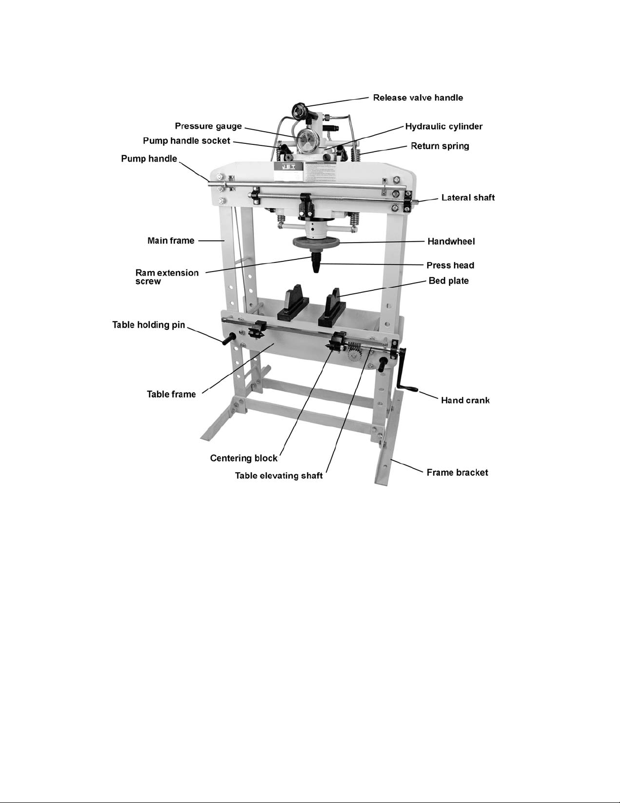
5.0 Features and Terminology
Model HP-35A shown as representative; other models may vary
Figure 1
6
Page 7

6.0 Assembly
Refer to Figure 1 for identification.
1. Use a lifting device, such as a hoist or forklift
with straps, to position machine upright.
2. Bolt the fram e brackets to the main frame with
the provided screws and hex nuts. Finger
tighten only.
3. The press should be placed within a well-lit
area, upon a level floor, preferably concrete.
Lower the press onto the floor, allowing it to
stabilize on the brackets. Fully tighten t he hex
nuts on the frame brackets.
4. The hex filler plug (see part s breakdown: item
#17 for HP-5A; #8A for HP-15A; #8D for HP35A) was installed for shipping purposes.
Remove this and replace it with the provided
vented plug.
5. Place the end of the pump handle into the
handle socket, and secure it with the screw.
7.0 Operation
Refer to Figure 1 for identification.
1. Remove all items from bed plates.
6. If desired, slide ram assembly laterally (15and 35-ton models only) by mounting the hand
crank onto the lateral shaft and rotating it. Do
not attempt to slide ram during operation.
7. The handwheel can be used to rapidly adjust
the ram extension screw into or out of the
plunger.
Note: The length of ram screw extending out
of the piston should be kept as short as
possible. Raise the table rather than extend
the screw to its travel limit.
8. Close valve by rotating release valve handle
clockwise as far as it will turn.
9. Pump the handle to lower the ram until it
makes light contact with workpiece. Align the
workpiece to ensure that desired contact point
is directly beneath the press head. Slowly
pump handle again until load begins to be
applied to workpiece.
10. Remove your hand from workpiece area and
step toward the side of the press (do not sta nd
directly in front of workpiece). Continue slowly
pumping to complete the operation.
11. When operation is complete, slowly retract ram
by incrementally turning release valve handle
counter-clockwise.
2. Remove table holding pins. (Support the table
frame on the HP-5A.)
3. Raise or lower table fram e to desired position,
so that when workpiece is m ounted, it will be
close to the ram press head.
Model HP-5A: Raise or lower table frame by
hand.
Models HP-15A,-35A: Rotate crank handle to
raise or lower table frame.
4. Re-insert table holding pins. Pins must be fully
engaged through front and back holes of the
frame.
5. Place workpiece onto bed plates.
Make sure workpiece is
center-loaded and secure before pressing, a nd
that table holding pins are properly inserted.
Some objects may have a tendency to pop out
or explode under pressure. Exercise proper
precautions.
8.0 Maintenance
• Keep the press clean, and periodically
lubricate joints and moving parts with light oil.
• Inspect the press before each use, for signs of
damage, bent pins, missing or loose bolts,
cracked welds, oil leaks, abnormal operation,
and the like. Make repairs o r replacements as
needed before putting the machine back into
service.
• Periodically remove filler plug (#17/HP-5A;
#8A/HP-15A; #8D/HP-35A) to check that
hydraulic cylinder is filled with oil. Top off as
needed with good quality hydraulic oil.
Reins ert filler plug.
• Flush and replace the oil in the hydraulic
cylinder approximately every 2 years. Ref er to
section 4.0 Specifications for oil capacity for
your particular model.
9.0 Replacement Parts
To order parts or reach our service department, call 1-800-274-6848, Monday through Friday (see our website
for busin ess hours, www. jettools.com). Having the Model Number and Serial Numbe r of your machine available
when you call will allow us to serve you quickly and accurately.
7
Page 8
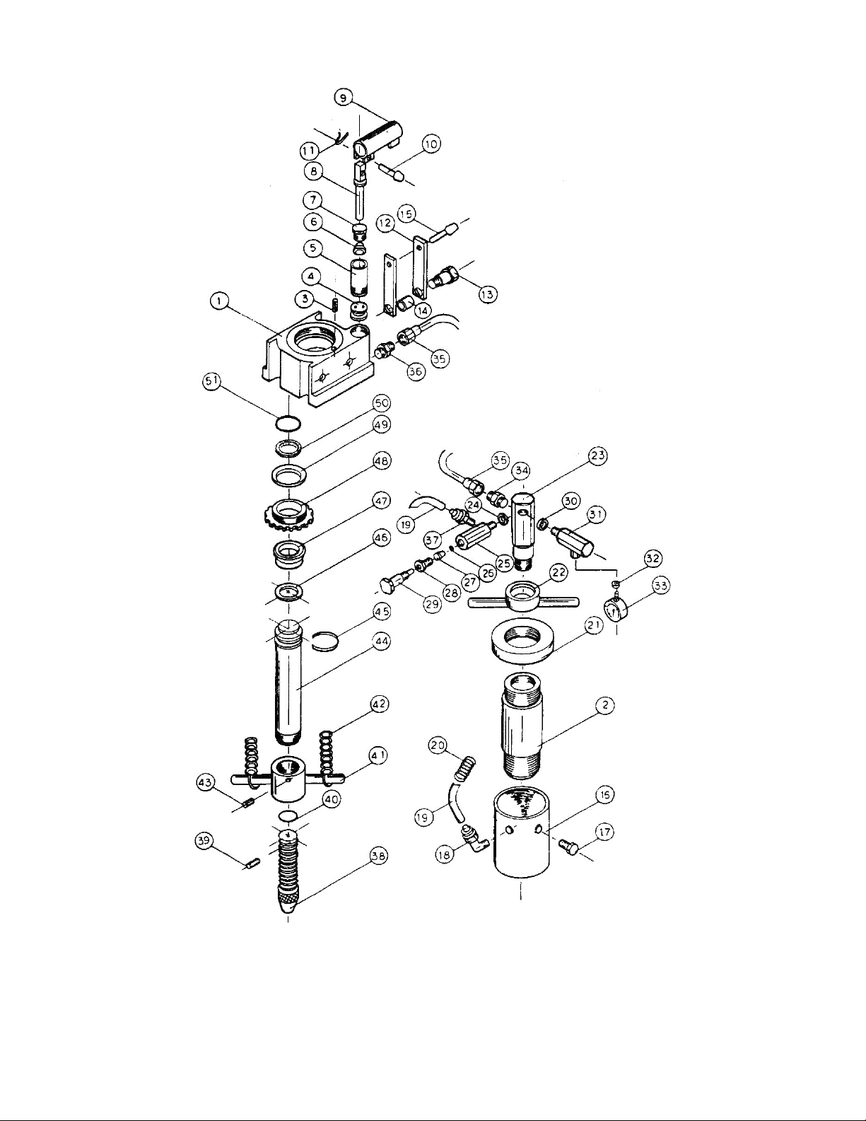
9.1.1 HP-5A Head Assembly – Exploded View
8
Page 9

9.1.2 HP-5A Head Assembly – Parts List
Index No. Part No. Description Size Qty
1 ................ HP5A-1...................... Hydrauli c Base.................................................. ............................................. 1
2 ................ HP5A-2...................... Cylin der............................................................. ............................................. 1
3 ................ HP5A-3...................... Base Filter ** ..................................................... ............................................. 1
4 ................ HP5A-4...................... Single Action Valve ........................................... ............................................. 1
5 ................ HP5A-5...................... Pump Cylinder .................................................. ............................................. 1
6 ................ HP5A-6...................... Cup Seal ** ....................................................... ............................................. 1
7 ................ HP5A-7...................... Release Valve Ass e mbly .................................. ............................................. 1
8 ................ HP5A-8...................... Pin..................................................................... ............................................. 1
9 ................ HP5A-9...................... Handl e Socket .................................................. ............................................. 1
10 .............. HP5A-10.................... Bolt.................................................................... ............................................. 1
11 .............. HP5A-11.................... C-Clip ................................................................ ............................................. 1
12 .............. HP5A-12.................... Linking Sleeve .................................................. ............................................. 1
13 .............. HP5A-13.................... Fixed Screw ...................................................... ............................................. 2
14 .............. HP5A-14.................... Spacer .............................................................. ............................................. 1
15 .............. HP5A-15.................... Bolt.................................................................... ............................................. 1
16 .............. HP5A-16.................... Reserv oir .......................................................... ............................................. 1
17 .............. HP5A-17.................... Hex Filler Plug w/Seal ** ................................... ............................................. 2
18 .............. HP5A-18.................... Brass Tube Connector ** .................................. ............................................. 1
19 .............. HP5A-19.................... Plastic Tube ** .................................................. ............................................. 1
20 .............. HP5A-20.................... Sprin g **............................................................ ............................................. 1
21 .............. HP5A-21.................... Top Base .......................................................... ............................................. 1
22 .............. HP5A-22.................... Sprin g Top Holder............................................. ............................................. 1
23 .............. HP5A-23.................... Oil Pass Connector ........................................... ............................................. 1
24 .............. HP5A-24.................... Washer **.......................................................... ............................................. 1
25 .............. HP5A-25.................... Release Valve Block ......................................... ............................................. 1
26 .............. HP5A-26.................... Steel Ball ** ....................................................... ............................................. 1
27 .............. HP5A-27.................... Rubber Spacer.................................................. ............................................. 1
28 .............. HP5A-28.................... Release Valve Assembly .................................. ............................................. 1
29 .............. HP5A-29.................... Release Valve Spin dle...................................... ............................................. 1
30 .............. HP5A-30.................... Washer **.......................................................... ............................................. 1
31 .............. HP5A-31.................... Release Valve Block ......................................... ............................................. 1
32 .............. HP5A-32.................... Washer **.......................................................... ............................................. 1
33 .............. HP5A-33.................... Pressu re Gauge................................................ ............................................. 1
34 .............. HP5A-34.................... Male Connect Tube .......................................... ............................................. 1
35 .............. HP5A-35.................... Bronze Tube ..................................................... ............................................. 1
36 .............. HP5A-36.................... Male Connector ................................................ ............................................. 1
37 .............. HP5A-37.................... Brass Tube Connector ** .................................. ............................................. 1
38 .............. HP5A-38.................... Extension Screw ............................................... ............................................. 1
39 .............. HP5A-39.................... Stopper Roll Pin ................................................ ............................................. 1
40 .............. HP5A-40.................... Stopper ** ......................................................... ............................................. 1
41 .............. HP5A-41.................... Connector Post ................................................. ............................................. 1
42 .............. HP5A-42.................... Return Spring.................................................... ............................................. 2
43 .............. TS-0270031 .............. Set Screw ......................................................... 5/16”-18 x 3/8” ..................... 1
44 .............. HP5A-44.................... Plun ger ............................................................. ............................................. 1
45 .............. HP5A-45.................... Support Ring ** ................................................. ............................................. 1
46 .............. HP5A-46.................... Support Seal ** ................................................. ............................................. 1
47 .............. HP5A-47.................... Cup Seal ** ....................................................... ............................................. 1
48 .............. HP5A-48.................... Plug Nut ............................................................ ............................................. 1
49 .............. HP5A-49.................... Gasket **........................................................... ............................................. 1
50 .............. HP5A-50.................... Oil Absorber ** .................................................. ............................................. 1
51 .............. HP5A-51.................... Seal................................................................... ............................................. 1
.................. HP5A-RK................... Repair Kit (includes items marked with **)........ ...............................................
9
Page 10

9.2.1 HP-5A Frame Assembly – Exploded View
10
Page 11

9.2.2 HP-5A Frame Assembly – Parts List
Index No. Part No. Description Size Qty
52 .............. HP5A-52.................... Frame Bracket .................................................. ............................................. 2
53 .............. TS-0060051 .............. Hex Cap Screw ................................................. 3/8”-16 x 1” .......................... 4
54 .............. TS-0561031 .............. Hex Nut ............................................................. 3/8”-16 ............................... 12
55 .............. HP5A-55.................... Frame Base Bracket ......................................... ............................................. 2
56 .............. TS-0060071 .............. Hex Cap Screw ................................................. 3/8”-16 x 1-1/2” .................... 8
57 .............. HP5A-57.................... Frame Base Bracket ......................................... ............................................. 2
58 .............. HP5A-58.................... Lower Frame Support ....................................... ............................................. 2
59 .............. HP5A-59.................... Table Holder Pin ............................................... ............................................. 2
60 .............. HP5A-60.................... Table Spindle .................................................... ............................................. 4
61 .............. HP5A-61.................... Crank Shaft Sleeve ........................................... ............................................. 4
62 .............. TS-0720111 .............. Lock Washer ..................................................... 1/2”....................................... 8
63 .............. TS-0561051 .............. Hex Nut ............................................................. 1/2"-13 ................................. 8
64 .............. HP5A-64.................... Bed Plate .......................................................... ............................................. 1
65 .............. HP5A-65.................... Main Frame (L-R post)...................................... ............................................. 2
66 .............. HP5A-66.................... Table Frame (Front).......................................... ............................................. 1
67 .............. HP5A-67.................... Table Frame (Rear) .......................................... ............................................. 1
68 .............. HP5A-68.................... Top Frame (rear) .............................................. ............................................. 1
69 .............. HP5A-69.................... Top Frame (front).............................................. ............................................. 1
70 .............. HP5A-70.................... Frame Spindle .................................................. ............................................. 1
71 .............. TS-0720131 .............. Lock Washer ..................................................... 5/8”....................................... 8
72 .............. TS-0561071 .............. Hex Nut ............................................................. 5/8”-11 ................................. 8
73 .............. TS-0071011 .............. Hex Cap Screw ................................................. 5/8”-11 x 1-1/2” .................... 4
74 .............. HP5A-74.................... Spin dle Sleeve .................................................. ............................................. 2
75 .............. TS-0071011 .............. Hex Cap Screw ................................................. 5/8”-11 x 1-1/2” .................... 4
76 .............. HP5A-76.................... Handl e Holder ................................................... ............................................. 2
77 .............. TS-0081031 .............. Hex Cap Screw ................................................. 5/16”-18 x 3/4” ..................... 4
78 .............. HP5A-78.................... Pump Handle .................................................... ............................................. 1
79 .............. HP5A-ID .................... Identification Label (not sh own) ........................ ............................................. 1
80 .............. HP5A-WL .................. Warning Label (not shown) ............................... ............................................. 1
11
Page 12

9.3.1 HP-15A Head Assembly – Exploded View
12
Page 13

9.3.2 HP-15A Head Assembly – Parts List
Index No. Part No. Description Size Qty
1 ................ HP15A-01.................. Hydrauli c Base.................................................. ............... .............................. 1
1A .............. HP15A-01A ............... Base Seal **...................................................... ............................................. 1
2 ................ HP15A-02.................. Cylinder............................................................. ............................................. 1
2A .............. HP15A-02A ............... Seal ** ............................................................... ............................................. 1
3 ................ HP15A-03.................. Support Rod...................................................... ............................................. 4
4 ................ HP15A-04.................. Single Action Valv e ........................................... ............................................. 1
4A .............. HP15A-04A ............... Base Filter ** ..................................................... ............................................. 1
5 ................ HP15A-05.................. Pump Cylinder .................................................. ............................................. 1
6 ................ HP15A-06.................. Piston ................................................................ ............................................. 1
6A .............. HP15A-06A ............... Cup Seal ** ....................................................... ............................................. 1
6B .............. HP15A-06B ............... Seal ** ............................................................... ............................................. 1
6C .............. HP15A-06C ............... Wiper Seal ** .................................................... ............................................. 1
7 ................ HP15A-07.................. Reserv oir .......................................................... ............................................. 1
8 ................ HP15A-08.................. Top Base .......................................................... ............................................. 1
8A .............. HP15A-08A ............... Hex Filler Plug w/ Seal...................................... ............................................. 1
8B .............. HP15A-08B ............... O-Ring **........................................................... ............................................. 5
8C .............. HP15A-08C ............... Spacer .............................................................. ............................................. 4
8D .............. TS-0720091 .............. Lock Washer ..................................................... 3/8”....................................... 4
8E .............. TS-0561031 .............. Hex Nut ............................................................. 3/8”-16 ................................. 4
8F .............. HP15A-08F ............... Brass Tube Connector ...................................... 1/8PT thread ........................ 2
9 ................ HP15A-09.................. Sprin g Top Holder............................................. ............................................. 1
10 .............. HP15A-10.................. Oil Pass Connector ........................................... ............................................. 1
10A ............ HP15A-10A ............... Spacer .............................................................. ............................................. 1
11 .............. HP15A-11.................. Plun ger ............................................................. ............................................. 1
11A ............ HP15A-11A ............... Support Seal ** ................................................. ............................................. 1
11B ............ HP15A-11B ............... Cup Seal ** ....................................................... ............................................. 1
11C ............ HP15A-11C ............... Support Ring ** ................................................. ............................................. 1
12 .............. HP15A-12.................. Seal ** ............................................................... ............................................. 1
13 .............. HP15A-13.................. Oil Absorber ** .................................................. ............................................. 1
14 .............. HP15A-14.................. Gasket **........................................................... ............................................. 1
15 .............. HP15A-15.................. Plug Nut Fixer ................................................... ............................................. 1
16 .............. HP15A-16.................. Connector Post ................................................. ............................................. 1
16A ............ HP15A-16A ............... Screw ................................................................ ............................................. 1
16B ............ HP15A-16B ............... Screw ................................................................ ............................................. 1
16C ............ HP15A-16C ............... Screw ................................................................ ............................................. 1
17 .............. HP15A-17.................. Handwheel Retainer Clip .................................. ............................................. 2
18 .............. HP15A-18.................. Handwh eel Spacer ........................................... ............................................. 1
19 .............. HP15A-19.................. Handwh eel ........................................................ ............................................. 1
20 .............. HP15A-20.................. Seal................................................................... ............................................. 1
21 .............. HP15A-21.................. Extension Screw ............................................... ............................................. 1
21A ............ HP15A-21A ............... Set Screw ......................................................... ............................................. 1
21B ............ HP15A-21B ............... Stopper Roll Pin ................................................ ............................................. 1
22 .............. HP15A-22.................. Press Head ....................................................... ............................................. 1
23 .............. HP15A-23.................. Release Valve Block ......................................... ............................................. 1
23A ............ HP15A-23A ............... Pressure Gauge................................................ ............................................. 1
23B ............ HP15A-23B ............... Plastic Tube ...................................................... ............................................. 1
23C ............ HP15A-23C ............... Washer ............................................................. ............................................. 1
23D ............ HP15A-23D ............... Spacer .............................................................. ............................................. 1
24 .............. HP15A-24.................. Steel Ball........................................................... ............................................. 1
25 .............. HP15A-25.................. Release Valve Seal **....................................... ............................................. 1
26 .............. HP15A-26.................. Release Valve Nut ............................................ ............................................. 1
27 .............. HP15A-27.................. Release Valve................................................... ............................................. 1
29 .............. HP15A-29.................. Male Connector ................................................ ............................................. 1
30 .............. HP15A-30.................. Male Connector ................................................ ............................................. 1
33 .............. HP15A-33.................. Bronze Tube ..................................................... ............................................. 1
34 .............. HP15A-34.................. Sliding Wheel .................................................... ............................................. 4
35 .............. HP15A-35.................. Lockin g Screw .................................................. ............................................. 4
36A ............ HP15A-36A ............... Hand Stopper.................................................... ............................................. 1
37 .............. HP15A-37.................. Complete Handle Sl eeve Assembly ................. ............................................. 1
13
Page 14

Index No. Part No. Description Size Qty
38 .............. HP15A-38.................. Fixed Screw ...................................................... ............................................. 1
39 .............. HP15A-39.................. Spacer .............................................................. ............................................. 1
40 .............. HP15A-40.................. Pin..................................................................... ............................................. 1
40A ............ HP15A-40A ............... Cotter Pin .......................................................... ............................................. 1
41 .............. HP15A-41.................. Return Spring.................................................... ............................................. 2
.................. HP15A-RKA .............. Hydraulic Repair Kit (includes items marked with **)........................................
14
Page 15

9.4.1 HP-15A Frame Assembly – Exploded View
15
Page 16

9.4.2 HP-15A Frame Assembly – Parts List
Index No. Part No. Description Size Qty
42 .............. HP15A-42.................. Shaft Holder ...................................................... ............................................. 1
42A ............ TS-0070011 .............. Hex Cap Screw ................................................. 1/2”-13 x 1” .......................... 2
43 .............. HP15A-43.................. Rolling Shaft Block without Thread ................... ............................................. 1
43A ............ TS-0060061 .............. Hex Cap Screw ................................................. 3/8”-16 x 1-1/4” .................... 3
44 .............. HP15A-44.................. Rolling Shaft Block with Th r ead ........................ ............................................. 1
44A ............ TS-0060051 .............. Hex Cap Screw ................................................. 3/8”-16 x 1” .......................... 1
44B ............ HP15A-44B ............... Washer ............................................................. ............................................. 4
45 .............. HP15A-45.................. Rolling Shaft ..................................................... ............................................. 1
45A ............ HP15A-45A ............... Nut .................................................................... ............................................. 2
46 .............. HP15A-46.................. Hand Crank....................................................... ............................................. 1
47 .............. HP15A-47.................. Pump Handle .................................................... ............................................. 1
47A ............ HP15A-47A ............... Rubber Grip ...................................................... ............................................. 1
48 .............. HP15A-48.................. Handl e Holder ................................................... ............................................. 2
48A ............ HP15A-48A ............... Handle Holder Screw ........................................ ............................................. 2
49 .............. HP15A-49.................. V-Block Body .................................................... ............................................. 1
49A ............ HP15A-49A ............... Body Sliding Plate............................................. ............................................. 2
49-1 ........... HP15A-49-1 .............. V-Block Body .................................................... ............................................. 1
49B ............ HP15A-49B ............... Body Sliding Plate............................................. ............................................. 2
49C ............ HP15A-49C ............... Hex Screw ........................................................ ............................................. 4
49D ............ HP15A-49D ............... Hex Screw ........................................................ ............................................. 3
49E ............ HP15A-49E ............... Stopper ............................................................. ............................................. 2
50 .............. HP15A-50.................. Center Tails ...................................................... ............................................. 2
51 .............. HP15A-51.................. Adjustable Center – Tail Body .......................... ............................................. 1
52 .............. HP15A-52.................. Adjustable Center – Tail Knob .......................... ............................................. 1
53 .............. HP15A-53.................. Crank Gear ....................................................... ............................................. 1
53A ............ HP15A-53A ............... Roll Pin ............................................................. ............................................. 1
54 .............. HP15A-54.................. Crank Gear Pawl .............................................. ............................................. 1
55 .............. HP15A-55.................. Pawl Stud Screw............................................... ............................................. 1
56 .............. HP15A-56.................. Crank Gear Shaft .............................................. ............................................. 1
57 .............. HP15A-57.................. Spin dle Sleeve .................................................. ............................................. 2
58 .............. HP15A-58.................. Table Holder Pin ............................................... ............................................. 1
59 .............. HP15A-59.................. Square Bar........................................................ ............................................. 1
59A ............ HP15A-59A ............... Center Tail Assembly Screw............................. ............................................. 2
60 .............. HP15A-60.................. Screw Spacer ................................................... ............................................. 2
61 .............. HP15A-61.................. Cable Sliding Spindle........................................ ............................................. 1
61A ............ HP15A-61A ............... Hex Nut ............................................................. ............................................. 2
62 .............. HP15A-62.................. Table Spindle .................................................... ............................................. 2
62A ............ HP15A-62A ............... Crank Shaft Sleeve ........................................... ............................................. 1
63 .............. HP15A-63.................. Cable Slide Wheel ............................................ ............................................. 1
64 .............. HP15A-64.................. Cable ................................................................ ............................................. 1
65 .............. HP15A-65.................. Wire Rope Clip.................................................. ............................................. 1
66 .............. HP15A-66.................. Top Frame (Rear) ............................................. ............................................. 1
67 .............. HP15A-67.................. Top Frame (Front) ............................................ ............................................. 2
68 .............. HP15A-68.................. Table Frame (Rear) .......................................... ............................................. 1
69 .............. HP15A-69.................. Table Frame (Front).......................................... ............................................. 1
70 .............. HP15A-70.................. Main Frame (Left/Right Pos t)............................ ............................................. 2
71 .............. HP15A-71.................. Lower Frame Support ....................................... ............................................. 2
72 .............. HP15A-72.................. Frame Bracket .................................................. ............................................. 2
72A ............ HP15A-72A ............... Frame Base Bracket ......................................... ............................................. 2
72B ............ HP15A-72B ............... Frame Base Bracket ......................................... ............................................. 2
72C ............ HP15A-72C ............... Bolt.................................................................... ............................................. 8
72D ............ HP15A-72D ............... Nut .................................................................... ............................................. 8
73 .............. HP15A-73.................. Bolt.................................................................... ............................................. 4
73A ............ HP15A-73A ............... Nut .................................................................... ............................................. 4
74 .............. HP15A-74.................. Hex Bolt ............................................................ ............................................. 4
76 .............. HP15A-76.................. Bed Plate .......................................................... ............................................. 2
77 .............. HP15A-77.................. Frame Spin dle .................................................. ............................................. 2
77A ............ HP15A-77A ............... Spindle Sleeve .................................................. ............................................. 2
78 .............. HP15A-ID .................. Identification Label (n ot sh own) ........................ ............................................. 1
80 .............. HP5A-WL .................. Warning Label (not shown) ............................... ............................................. 1
16
Page 17

9.5.1 HP-35A Head Assembly – Exploded View
17
Page 18

9.5.2 HP-35A Head Assembly – Parts List
Index No. Part No. Description Size Qty
1 ................ HP35A-01.................. Base.................................................................. ............................................. 1
1A .............. HP35A-01A ............... Base Filter ** ..................................................... ............................................. 2
2 ................ HP35A-02.................. Cylinder............................................................. ............................................. 1
2A .............. HP35A-02A ............... Spacer .............................................................. ............................................. 1
3 ................ HP35A-03.................. Support Rod...................................................... ............................................. 4
4 ................ HP35A-04.................. Single Action Valv e ........................................... ............................................. 1
4-1 ............. HP35A-04-1 .............. Sin gle Action Valve ........................................... ............................................. 1
5 ................ HP35A-05.................. Pump Cylin d er – Fast ....................................... ............................................. 1
5-1 ............. HP35A-05-1 .............. Pump Cylinder – Slow ...................................... ............................................. 1
5A .............. HP35A-05A ............... O-Ring **........................................................... ............................................. 1
5A-1 ........... HP35A-05A-1 ............ O-Ring **........................................................... ............................................. 1
6 ................ HP35A-06.................. Shaft ................................................................. ............................................. 1
6-1 ............. HP35A-06-1 .............. Sh aft ................................................................. ............................................. 1
6A .............. HP35A-06A ............... Cup Seal ** ....................................................... ............................................. 1
6A-1 ........... HP35A-06A-1 ............ Cup Seal ** ....................................................... ............................................. 1
6B .............. HP35A-06B ............... Wiper Seal ** .................................................... ............................................. 1
6B-1 ........... HP35A-06B-1 ............ Wiper Seal ** .................................................... ............................................. 1
6C .............. HP35A-06C ............... O-Ring **........................................................... ............................................. 1
6C-1 .......... HP35A-06C-1 ............ O-Ring **........................................................... ................ ............................. 1
7 ................ HP35A-07.................. Reserv oir .......................................................... ............................................. 1
8 ................ HP35A-08.................. Hydrauli c Base Top .......................................... ............................................. 1
8A .............. TS-0720111 .............. Lock Washer ..................................................... 1/2" ...................................... 4
8B .............. TS-0561051 .............. Hex Nut ............................................................. 1/2”-13 ................................. 4
8C .............. HP35A-08C ............... Brass Tube Connector ...................................... ............................................. 3
8D .............. HP35A-08D ............... Hex Filler Plug w/ Seal...................................... ............................................. 1
9 ................ HP35A-09.................. Connector Post ................................................. ............................................. 1
10 .............. HP35A-10.................. Oil Pass Connector ........................................... ............................................. 1
10A ............ HP35A-10A ............... Spacer .............................................................. ............................................. 1
11 .............. HP35A-11.................. Plun ger ............................................................. ............................................. 1
11A ............ HP35A-11A ............... Support Ring ** ................................................. ............................................. 1
11B ............ HP35A-11B ............... Spacer Ring ...................................................... ............................................. 1
11C ............ HP35A-11C ............... Cup Seal ** ....................................................... ............................................. 1
12 .............. HP35A-12.................. Gasket .............................................................. ............................................. 1
12A ............ HP35A-12A ............... O-Ring **........................................................... ............................................. 1
13 .............. HP35A-13.................. Seal ** ............................................................... ............................................. 1
14 .............. HP35A-14.................. Plunger Plate w/Gasket .................................... ............................................. 1
15 .............. TS-0209061 .............. Socket Head Cap Screw................................... 3/8”-16 x 1-1/4” .................... 6
16 .............. HP35A-16.................. Connector Post ................................................. ............................................. 1
16A ............ HP35A-16A ............... Socket Set Screw ............................................. ............................................. 1
16B ............ HP35A-16B ............... Socket Head Cap Screw................................... ............................................. 1
16C ............ HP35A-16C ............... Socket Set Screw ............................................. ............................................. 1
17 .............. HP35A-17.................. Handwheel Retainer Clip .................................. ............................................. 2
18 .............. HP35A-18.................. Handwh eel Spacer ........................................... ............................................. 1
19 .............. HP35A-19.................. Handwh eel ........................................................ ............................................. 1
20 .............. HP35A-20.................. Seal................................................................... ............................................. 1
21 .............. HP35A-21.................. Extension Screw ............................................... ............................................. 1
21A ............ HP35A-21A ............... Stopper Roll Pin ................................................ ............................................. 1
21B ............ HP35A-21B ............... Set Screw ......................................................... ............................................. 1
22 .............. HP35A-22.................. Press Head ....................................................... ............................................. 1
23 .............. HP35A-23.................. Release Valve Block ......................................... ............................................. 1
23A ............ HP35A-23A ............... Spacer .............................................................. ............................................. 1
23B ............ HP35A-23B ............... Pressure Gauge................................................ ............................................. 1
23C ............ HP35A-23C ............... Plastic Tube ...................................................... ............................................. 1
24 .............. HP35A-24.................. Steel Ball........................................................... ............................................. 1
25 .............. HP35A-25.................. Release Valve Seal **....................................... ............................................. 1
26 .............. HP35A-26.................. Release Valve Nut ............................................ ............................................. 1
27 .............. HP35A-27.................. Release Valve................................................... ............................................. 1
28 .............. HP35A-28.................. Safety Valve Bl ock ............................................ ............................................. 1
28A ............ HP35A-28A ............... Plastic Tube ...................................................... ............................................. 1
18
Page 19

Index No. Part No. Description Size Qty
28B ............ HP35A-28B ............... Steel Ball........................................................... ............................................. 1
28C ............ HP35A-28C ............... Safety Spring .................................................... ............................................. 1
28D ............ HP35A-28D ............... Safety Valve Set Screw .................................... ............................................. 1
28E ............ HP35A-28E ............... Brass Tube Connector ...................................... ............................................. 1
28F ............ HP35A-28F ............... Releas e Valve Seal **....................................... ............................................. 1
28G ........... HP35A-28G ............... Wash er ............................................................. ............................................. 1
28H ............ HP35A-28H ............... Hex Nut ............................................................. ............................................. 1
28I ............. HP35A-28I ................ Spacer .............................................................. ............................................. 1
29 .............. HP35A-29.................. Male Connector ................................................ ............................................. 2
30 .............. HP35A-30.................. Male Connector ................................................ ............................................. 2
33 .............. HP35A-33.................. Bronze Tube ..................................................... ............................................. 2
34 .............. HP35A-34.................. Sliding Wheel .................................................... ............................................. 4
35 .............. HP35A-35.................. Hex Locking Bolt ............................................... ............................................. 4
36 .............. HP35A-36.................. Handl e Socket .................................................. ............................................. 2
36A ............ TS-0561031 .............. Hex Nut ............................................................. 3/8”-16 ................................. 2
36B ............ TS-0060051 .............. Hex Cap Screw ................................................. 3/8”-16 x 1” .......................... 2
37 .............. HP35A-37.................. Linking Sleeve .................................................. ............................................. 4
38 .............. HP35A-38.................. Bottom Fixed Bolt ............................................. ............................................. 2
38A ............ HP35A-38A ............... Spacer .............................................................. ............................................. 2
39 .............. HP35A-39.................. Bolt.................................................................... ............................................. 2
39A ............ HP35A-39A ............... C-Clip ................................................................ ............................................. 4
40 .............. HP35A-40.................. Bolt.................................................................... ............................................. 2
41 .............. HP35A-41.................. Return Spring.................................................... ............................................. 2
.................. HP35A-RK................. Hydraulic Repair Kit (includes items marked with **)........................................
19
Page 20

9.6.1 HP-35A Frame Assembly – Exploded View
20
Page 21

9.6.2 HP-35A Frame Assembly – Parts List
Index No. Part No. Description Size Qty
42 .............. HP35A-42.................. Shaft Holder ...................................................... ............................................. 1
42A ............ HP35A-42A ............... Hex Cap Head Bolt ........................................... ............................................. 2
43 .............. HP35A-43.................. Rolling Shaft Block............................................ ............................................. 1
43A ............ TS-0060061 .............. Hex Cap Screw ................................................. 3/8”-16 x 1-1/4” .................... 2
44 .............. HP35A-44.................. Rolling Shaft Block............................................ ............................................. 1
44A ............ TS-0060051 .............. Hex Cap Screw ................................................. 3/8”-16 x 1” .......................... 2
44B ............ TS-0680041 .............. Flat Washer ...................................................... 3/8”....................................... 8
45 .............. HP35A-45.................. Sliding Shaft...................................................... ............................................. 1
45A ............ TS-0561072 .............. Hex Nut ............................................................. 5/8”-18 ................................. 1
46 .............. HP35A-46.................. Hand Crank....................................................... ............................................. 1
47 .............. HP35A-47.................. Handl e .............................................................. ............................................. 1
48 .............. HP35A-48.................. Handl e Holder ................................................... ............................................. 2
48A ............ TS-0051051 .............. Hex Cap Screw ................................................. 5/16”-18 x 1” ........................ 4
49 .............. HP35A-49.................. Center Post Assembly (left) .............................. ............................................. 1
50 .............. HP35A-50.................. Center Post Assembly ( right) ............................ ............................................. 1
51 .............. HP35A-51.................. Fixed Holder ..................................................... ............................................. 1
52 .............. HP35A-52.................. Shaft Fixed Block .............................................. ............................................. 1
53 .............. HP35A-53.................. Drive Gear Shaft Assembly .............................. ............................................. 1
54 .............. HP35A-54.................. Hex Nut ............................................................. ............................................. 1
55 .............. HP35A-55.................. Worm Gear w/ Shaft ......................................... ............................................. 1
56 .............. TS-0060051 .............. Hex Cap Screw ................................................. 3/8”-16 x 1” .......................... 4
57 .............. HP35A-57.................. Spacer Sleeve .................................................. ............................................. 1
58 .............. HP35A-58.................. Table Holder Pin ............................................... ............................................. 1
59 .............. HP35A-59.................. Square Bar........................................................ ............................................. 1
60 .............. HP35A-60.................. Screw Spacer ................................................... ............................................. 2
60A ............ TS-0060151 .............. Hex Cap Screw ................................................. 3/8” x 3-1/2” ......................... 2
61 .............. HP35A-61.................. Slide Wheel Shaft ............................................. ............................................. 2
62 .............. HP35A-62.................. Table Bolt.......................................................... ............................................. 4
62A ............ HP35A-62A ............... Spindle Sleeve .................................................. ............................................. 8
62B ............ TS-0720131 .............. Lock Washer ..................................................... 5/8”..................................... 12
62C ............ TS-0561071 .............. Hex Nut ............................................................. 5/8”-11 ............................... 12
63 .............. HP35A-63.................. Cable Slide Wheel ............................................ ............................................. 2
64 .............. HP35A-64.................. Wire Rope Clip.................................................. ............................................. 2
65 .............. HP35A-65.................. Cable ................................................................ ............................................. 1
66 .............. HP35A-66.................. Top Frame (Rear) ............................................. ............................................. 1
67 .............. HP35A-67.................. Top Frame (Front) ............................................ ............................................. 1
68 .............. HP35A-68.................. Table Frame (Rear) .......................................... ............................................. 1
69 .............. HP35A-69.................. Table Frame (Front).......................................... ............................................. 1
70 .............. HP35A-70.................. Main Frame....................................................... ............................................. 2
71 .............. HP35A-71.................. Lower Frame Support ....................................... ............................................. 2
72 .............. HP35A-72.................. Base Frame Bracket ......................................... ............................................. 2
72A ............ HP35A-72A ............... Frame Bracket (Left) ......................................... ............................................. 2
72B ............ HP35A-72B ............... Frame Bracket (Righ t) ...................................... ............................................. 2
72C ............ TS-0071011 .............. Hex Cap Screw ................................................. 5/8”-11 x 1-1/2” .................... 4
73 .............. TS-0071031 .............. Hex Cap Screw ................................................. 5/8”-11 x 2” .......................... 8
73A ............ TS-0561071 .............. Hex Nut ............................................................. 5/8”-11 ............................... 12
74 .............. HP35A-74.................. Hex Head Bolt................................................... 3/4” x 2”................................ 8
74A ............ TS-0720141 .............. Lock Washer ..................................................... 3/4”..................................... 12
75 .............. TS-0561081 .............. Hex Nut ............................................................. 3/4"-10 ............................... 12
76 .............. HP35A-76.................. V-Block Bed Plate ............................................. ............................................. 2
77 .............. HP35A-77.................. Top Link Bolt ..................................................... ............................................. 2
77A ............ HP35A-77A ............... Spacer Sleeve .................................................. ............................................. 2
78 .............. HP35A-ID .................. Identification Label (n ot sh own) ........................ ............................................. 1
80 .............. HP5A-WL .................. Warning Label (not shown) ............................... ............................................. 1
21
Page 22

This page intentionally left blank.
22
Page 23

This page intentionally left blank
23
Page 24

427 New Sanford Road
LaVergne, Tennessee 37086
Phone: 800-274-6848
www.jettools.com
24
 Loading...