

Page 1

PADIN5
PADIN5
Installation and Operation Manual
Instruction d’inst allation et d’opération
Page 2

INTRODUCTION
Thank you for choosing a JENSEN product. We’ve tried to make the instructions in this owner’s
manual clear and easy to follow. If you take a few minutes to look through it, you’ll learn how to use
all of the features of your new JENSEN stereo for maximum enjoyment.
Contents
Precautions ....................................................................................................................................1
Preparation.....................................................................................................................................1
Installation..................................................................................................................................... 2
Operation....................................................................................................................................... 5
Troubleshooting..............................................................................................................................7
Specifications.................................................................................................................................8
Warranty.........................................................................................................................................8
INTRODUCTION
Merci d’avoir choisi un produit Jensen. Nous avons essayé de rendre les instructions dans ce
mode d’emploi du propriétaire claires et faciles à suivre. Si vous prenez quelques minutes pour le
lire, vous apprendrez comment utiliser toutes les fonctions de votre stéréo JENSEN nouveau pour
un plaisir maximal.
Table des matières
Précautions ....................................................................................................................................9
Preparation.....................................................................................................................................9
Installation................................................................................................................................... 10
Operation..................................................................................................................................... 13
Dépannage...................................................................................................................................15
Specifications...............................................................................................................................16
Garantie........................................................................................................................................16
PADIN5
ii
Page 3

PADIN5
PRECAUTIONS
• Use the Proper Power Supply.
This product is designed to operate with a 12 volt DC, negative ground battery system (the
standard system in a North American car).
• Use Authorized Service Centers.
Do not attempt to disassemble or adjust this precision product; contact a professional for
assistance.
• Avoid Moisture.
To reduce the risk of fire or electric shock, do not expose this equipment to rain or moisture.
• Use Recommended Accessories.
TO REDUCE THE RISK OF FIRE OR ELECTRIC SHOCK AND ANNOYING
INTERFERENCE, USE ONLY THE RECOMMENDED ACCESSORIES.
PREPARATION
It’s a good idea to read all of the instructions before beginning the installation. We recommend
having your Jensen PADIN5 installed by a reputable installation shop.
Tools and Supplies
You will need these tools and supplies to install your PADIN5:
• Torx type, flat-head and Philips screwdrivers
• Wire cutters and strippers
• Tools to remove existing radio (screwdriver, socket wrench set or other tools)
• Electrical tape
• Crimping tool
• Volt meter/test light
• Crimp connections
• 18 gauge wire for power connections
• 16 – 18 gauge speaker wire
Speaker Requirements: Only connect speakers rated in the load impedance of 4 ohms.
Speakers with a load impedance less than 4 ohms could damage the unit.
Disconnecting the Battery
To prevent a short circuit, be sure to turn off the ignition and remove the negative (-) battery cable
prior to installation.
NOTE: If the PADIN5 is to be installed in a vehicle equipped with an on-board drive or
navigation computer, do not disconnect the battery cable. If the cable is disconnected, the
computer memory may be lost. Under these conditions, use extra caution during
installation to avoid causing a short circuit.
1
Page 4
INSTALLATION
5
4
8
7
PADIN5
Before you begin, always disconnect the battery negative terminal.
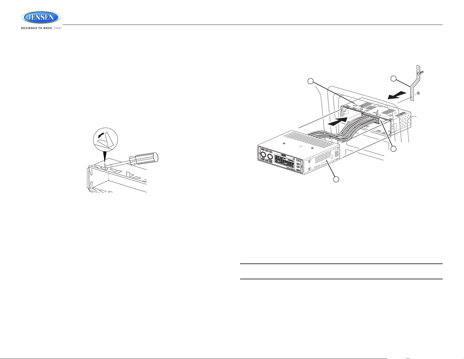
Universal Installation Using Mounting Sleeve
1. Slide the mounting sleeve off of the chassis if it has not already been removed. If it is locked
into position, use the removal keys (supplied) to disengage it.
2. Check the dashboard opening size by sliding the mounting sleeve into it. If the opening is not
large enough, carefully cut or file as necessary until the sleeve easily slides into the opening.
Do not force the sleeve into the opening or cause it to bend or bow. Check that there will be
sufficient space behind the dashboard for the radio chassis.
3. Locate the series of bend tabs along the top, bottom and sides of the mounting sleeve. With
the sleeve fully inserted into the dashboard opening, bend as many of the tabs outward as
necessary to firmly secure the sleeve to the dashboard.
PADIN5
4. Place the unit in front of the dashboard opening so the wiring can be brought through the
mounting sleeve.
5. Follow the wiring diagram carefully and make certain all connections are secure and
insulated with crimp connectors or electrical tape to ensure proper operation.
6. After completing the wiring connections, turn the unit on to confirm operation (vehicle ignition
switch must be on). If the unit does not operate, recheck all wiring until the problem is
corrected. Once proper operation is achieved, turn the ignition switch off and proceed with
final mounting of the chassis.
7. Carefully slide the unit into the mounting sleeve making sure it is right-side-up until it is fully
seated and the spring clips lock it into place.
8. Attach one end of the perforated support strap (supplied) to the screw stud on the rear of the
chassis using the hex nut provided. Fasten the other end of the perforated strap to a secure
part of the dashboard either above or below the radio using the screw and hex nut provided.
Bend the strap, as necessary, to position it.
CAUTION: The rear of the unit must be supported with the strap to prevent damage to the
dashboard from the weight of the radio or improper operation due to vibration.
9. Test operation by referring to the operating instructions for the unit.
2
Page 5
PADIN5
Jensen Connector
1
2
DVDB01 Connector (DVD Player Sold Separately)
2 3 4
5
1
DVD IR
Wiring
Perform the following steps to install the radio using a wiring adapter
(purchased separately):
1. Splice or crimp wires.
2. Attach wiring adapter to vehicle wiring harness.
3. Re-connect the battery negative terminal and test radio operation to
confirm correct wiring.
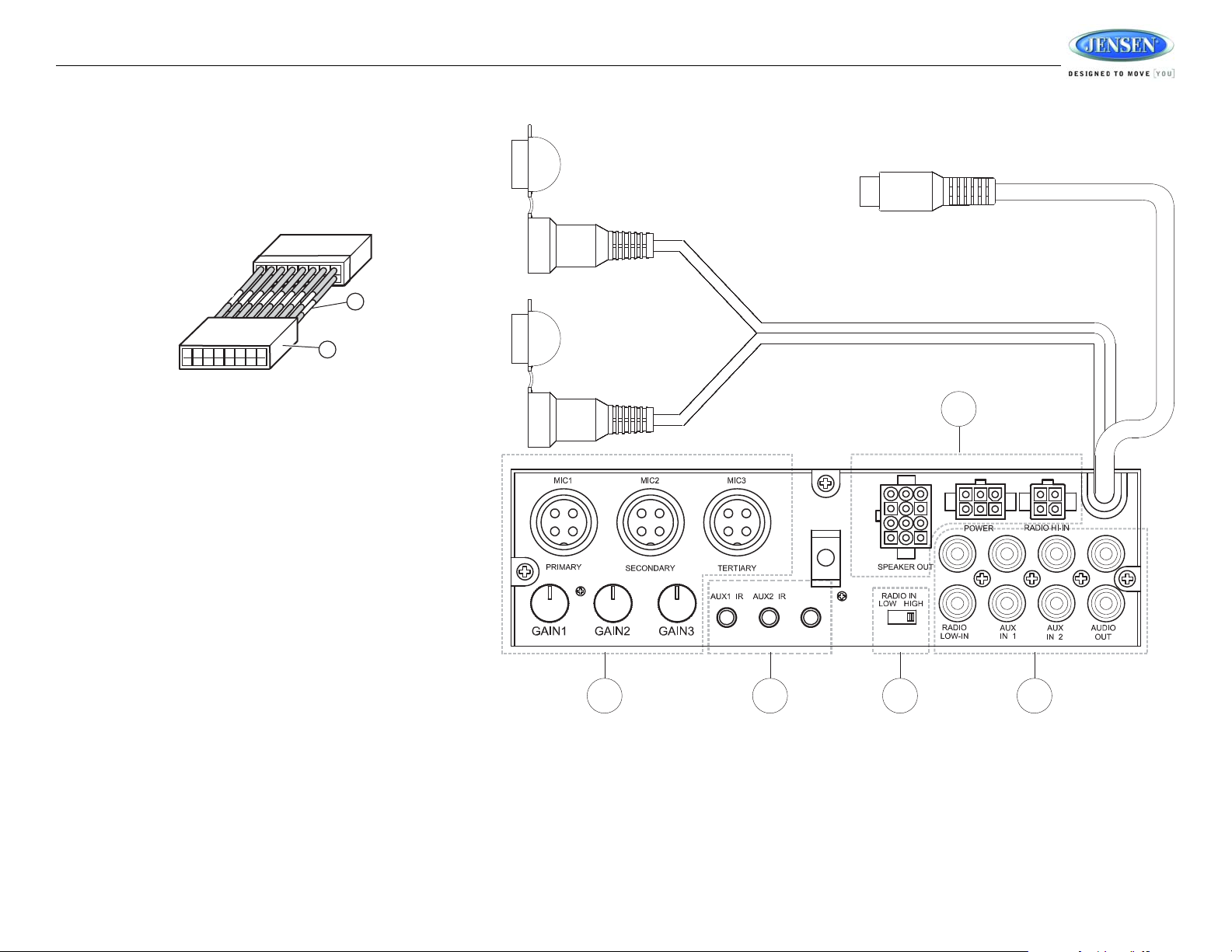
Rear Radio Controls and Connectors
1. MICROPHONE CONNECTIONS
See “Using Microphones” on page 6.
2. IR CONNECTIONS
See “AUX IR and DVD IR Connections” on page 5.
3. RADIO IN LOW/HIGH SWITCH
• Select “LOW” when you are using low-level RCA radio input (RADIO
LOW-IN).
• Select “HIGH” when using hi-level radio input (RADIO HI-IN).
4. RCA CONNECTIONS
• RADIO LOW-IN: Connect to the RCA output from your radio.
• AUX IN 1 and AUX IN 2: See “AUX RCA Connections” on page 5.
• AUDIO OUT: Connect to an additional amplifier.
5. HIGH LEVEL WIRING CONNECTIONS
See Table 1 on page 4 for specific wiring connections.
3
Page 6
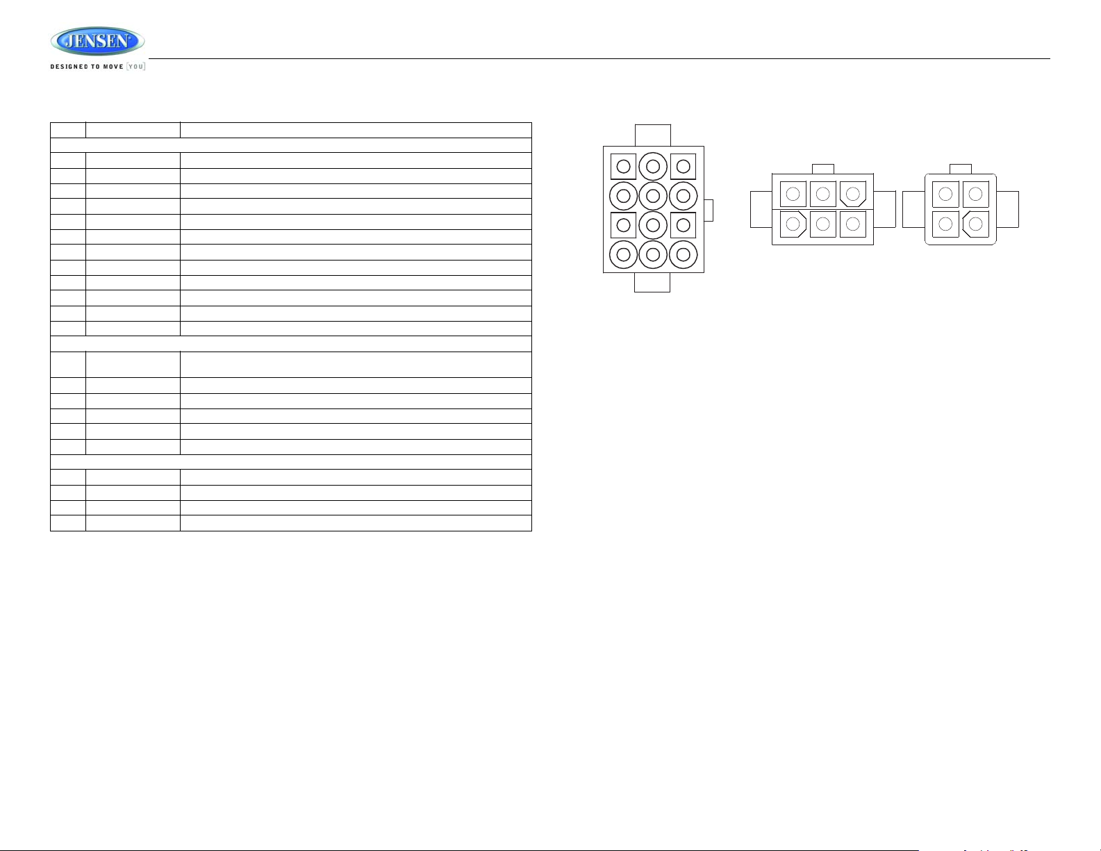
Table 1: Wiring Connections
SPEAKER OUT
RADIO HI-IN
POWER
1
2
3
45
6
1
2
3
4
1
2
3
4
6
5
7
8
9
10
11
12
PADIN5 Connector PIN View
Pin # Wire Color Function
SPEAKER OUT
1 White Driver Speaker L+
2 Gray Driver Speaker R+
3 Green Passenger Speaker L+
4 Violet Passenger Speaker R+
5 White/Black Driver Speaker L6 Gray/Black Driver Speaker R7 Green/Black Passenger Speaker L8 Violet/Black Passenger Speaker R9 Orange EXT Speaker +
10 Orange/Black EXT Speaker 11 White/Red Trigger DC +12V output for AUX2 mode
12 White/Blue Trigger DC +12V output for AUX1 mode
POWER
1 Red DC Input: Connect to +12V switched power source. The radio will not work if thi s
2 Pink Trigger +12V Output for DVD mode
3 Yellow +12V Plus Constant Power
4 Empty Not Used
5 Blue/White Trigger +12V Output
6 Black Ground
RADIO HI-IN
1 White Speaker Left +
2 Gray Speaker Right +
3 White/Black Speaker Left 4 Gray/Black Speaker Right -
wire is not connected.
PADIN5
4
Page 7

PADIN5
1
2
3
PADIN5
4
5
6
7
8
12
11
10
9
AUX2 IRAUX1 IR DVD IR
OPERATION
Mute
Press the MUTE button (4) to silence the amplifier. Press MUTE again to resume audio.
Radio Source Button
Press the RADIO source button (5) to select radio input. The illuminated RADIO indicator will
change from amber to green, indicating the selection was made.
DVD Source Button
Press the DVD button (6) to play the audio from the optional DVDB01 DVD player through the
selected speakers. The illuminated DVD indicator will change from amber to green, indicating the
selection was made. An 8-Pin DIN connector and left and right audio input cables allow you to
control the Jensen DVDB01 through the PADIN5.
NOTE: DVD audio is available for non-Jensen DVD players. To access this feature, press
and hold the DVD button (6) for 2 seconds to control audio for any DVD player when the
communication cable is not connected.
Basic Operation
Power
Press the POWER button (1) or any other button on the face of the unit to turn the unit on. Press
POWER to turn the unit off.
Volume Control - Driver
To increase the volume for the driver, rotate the DRIVER volume control knob (2) clockwise.
AUX Source Button
Press the AUX button (7) once to select AUX 1 input. T o select AUX 2, press the AUX button again
while in AUX 1 mode. The AUX 2 indicator on the display will change from amber to green.
AUX RCA Connections
The RCA connections for the AUX input audio channel, labeled AUX IN 1 and
AUX IN 2, are located on the back of the unit.
Rotate the DRIVER knob counter-clockwise to decrease the volume.
Volume Control - Passenger
To increase the volume for the passenger, rotate the PASSENGER volume control knob (3)
clockwise. Rotate the PASSENGER knob counter-clockwise to decrease the volume.
Select Driver Source
To select the Driver source, press the DRIVER volume control knob (2). The DRIVER MODE icon
will flash and turn from amber to green, indicating that Driver Mode was selected. Press the
RADIO, DVD or AUX button (press twice for AUX 2) to select the desired source. The selected
source will be indicated on the display. To exit Driver mode, press and hold the DRIVER volume
AUX IR and DVD IR Connections
There are three 3.5mm jacks (one for AUX1, one for AUX2 and one
for DVD IR) on the back of the unit in which you can plug the IR
source signals. The AUX IN device can then be controlled with the
AUX remote through the IR sensor on the front of the PADIN5.
control knob for 2 seconds.
Select Passenger Source
NOTE: If using a wireless remote with the DVDB01, the DVDB01 wired IR connection must
be plugged into the AUX1 IR, AUX2 IR or DVD IR jack.
To select the Passenger source, press the PASSENGER volume control knob (3). The
PASSENGER MODE icon will flash and turn from amber to green. Select the desired source
(indicated on the display). To exit Passenger mode, press and hold the PASSENGER volume
control knob for 2 seconds.
External PA Source Button
The External PA source can be selected to broadcast the audio from a microphone. To select the
External PA source, press the EXT PA button (8). The illuminated EXTERNAL PA indicator will
change from amber to green, indicating the selection was made.
5
Page 8

Using Microphones
MIC 1
MIC 2
MIC 3
GAIN 1
GAIN 2
GAIN 3
External Microphone Connections
There are three microphone inputs on the back of the unit labeled Primary , Secondary and Tertiary .
Each microphone has it's own level control located below the connector, which is used to adjust
the volume level of the PA. The Primary microphone takes priority over the other two microphones.
If the Secondary or Tertiary microphone is being used and the Primary microphone is keyed, only
the Primary microphone audio will be heard in the PA. If the Tertiary microphone is keyed when the
Secondary microphone is in use, the Secondary microphone will take priority over the Tertiary
microphone (only the Secondary microphone will be heard). There are individual gain controls for
each microphone on the rear of the unit. When a microphone is keyed, the audio from the Driver
and Passenger modes will be muted and the audio from the microphone will be heard in the Driver,
Passenger and EXT PA speakers.
Controlling the Optional DVDB01 DVD Player
PADIN5
<<
Button
Press the <<
on a CD.
Press and hold for 2 seconds to Rewind (RW) through the scene. Press and hold repeatedly to
increase the RW speed from 2x, 4x, 8x, 20x and then normal play.
Press the PLAY/|| button (9) at any time to resume normal play.
STOP Button
Press the STOP button (10) to stop DVD play. Press the PLAY/|| button (9) to resume DVD play at
the last scene that was displayed.
Pressing STOP again will restart the DVD at the beginning.
(reverse) button (12) to return to the previous chapter on a DVD or the previous track
NOTE: The DVDB01 is sold separately. It is not supplied with the PADIN5.
PLAY/|| Button
Press the PLAY/|| (Play /Pause) button (9) to pause DVD play. Press PLAY/|| again to resume
play.
>>
Button
Press the >>
(forward) button (11) to advance to the next chapter in a DVD or the next track on a
CD.
Press and hold for 2 seconds to Fast Forward (FF) through the scene. Press and hold repeatedly
to increase the FF speed from 2x, 4x, 8x, 20x and then normal play. Press the PLAY/|| button (9) at
any time to resume normal play.
6
Page 9

PADIN5
TROUBLESHOOTING
Problem Cause Corrective Action
Does not operate (display does
not light)
No power to unit Inline fuse blown Check/replace fuse
No speakers operate Speaker harness not con-
Not all speakers operate Incorrect splices or connec-
Blows fuses Power wire shorting to ground Make sure wire is not pinched.
CD skips too much Receiver mount is not solid or
For technical assistance, please visit www.asaelectronics.com.
No power to yellow wire No
power to red wire
Inline fuse blown Replace fuse
nected
tions
Speaker wires shorting to chas-
sis ground or to each other
Speaker wires shorting to
ground
Incorrect fuse/fuse too small Install fuse of correct rating.
backstrap is not secure
Check connection with test
light.
Check fuse with test light.
Connect speaker harness.
Check speaker wires.
Check all splices and connections.
Check splices and connections.
Make sure wire is not pinched.
Check mounting and backstrap and tighten if needed.
7
Page 10

PADIN5
SPECIFICATIONS
Power supply. . . . . . . . . . . . . . . . . . . . . . . . . . . . . . . . . . . . . .10.5-32 VDC, negative ground
Speaker output impedance . . . . . . . . . . . . . . . . . . . . . . . . . . . . . . . . . . . . . . . . . . . 4-8 Ohms
Fuses. . . . . . . . . . . . . . . . . . . . . . . . . . . . . . . . . . . . . . . . . . . . . . . . . fast blow ATC (15 amp)
Dimensions . . . . . . . . . . . . . . . . . . . . . . . . . . . . . . . . . . 7" x 6-1/2" x 2" (178 x 165 x 51 mm)
Specifications subject to change without notice.
This device complies with Part 15 of the FCC Rules. Operation is subject to the following two
conditions:
(1) This device may not cause harmful interference.
(2) This device must accept any interference received, including interference that may cause
undesired operation.
NOTE: The manufacturer is not responsible for any radio or TV interference caused by
unauthorized modifications to this equipment. Such modifications could void the User’s
authority to operate the equipment.
LIMITED WARRANTY
90 Day / 12 Month Limited Warranty
AUDIOVOX SPECIALIZED APPLICATIONS, LLC (the Company) warrants to the original retail
purchaser of this product that should this product or any part thereof, under normal use and
conditions, be proven defective in material or workmanship within 90 days from the date of original
purchase, such defect(s) will be repaired or replaced (at the Company's option) without charge for
parts and repair labor. After the initial 90 day period and for a period of 12 months from the date of
the original purchase, the Company will supply at no charge a replacement for any defective
part(s).
To obtain repair or replacement within the terms of this warranty, the end user should contact the
O.E.M. The product is to be delivered to the OEM or original place of purchase, with proof of
warranty coverage (e.g. dated bill of sale, and serial number of the unit, and vin#), specification of
defect(s), transportation prepaid, to an approved warranty station. This warranty does not extend
to the elimination of externally generated static or noise, to the correction of antenna problems, to
costs incurred for removal or reinstallation of the product, or to damage to any tapes, CD's, DVD's,
speakers, accessories, or electrical systems. This warranty does not apply to any product or part
thereof which, in the opinion of the Company, has been damaged through alteration, improper
installation, mishandling, misuse, neglect, or accident. THE EXTENT OF THE COMPANY'S
LIABILITY UNDER THIS WARRANTY IS LIMITED TO THE REPAIR OR REPLACEMENT
PROVIDED ABOVE, AND, IN NO EVENT, SHALL THE COMPANY'S LIABILITY EXCEED THE
PURCHASE PRICE PAID BY THE PURCHASER FOR THE PRODUCT.
This warranty is in lieu of all other express warranties or liabilities. ANY IMPLIED WARRANTIES,
INCLUDING ANY IMPLIED WARRANTY OF MERCHANTABILITY, SHALL BE LIMITED TO THE
DURATION OF THIS WARRANTY. ANY ACTION FOR BREECH OF ANY WARRANTY
HEREUNDER INCLUDING ANY IMPLIED WARRANTY OF MERCHANTABILITY MUST BE
BROUGHT WITHIN A PERIOD OF 30 DAYS FROM THE DATE OF ORIGINAL PURCHASE. IN
NO CASE SHALL THE COMPANY BE LIABLE FOR ANY CONSEQUENTIAL OR INCIDENTAL
DAMAGES FOR BREECH OF THIS OR ANY OTHER WARRANTY, EXPRESS OR IMPLIED
WHATSOEVER. No person or representative is authorized to assume for the Company any
liability other that expressed herein in connection with the sale of this product.
Some states do not allow limitations on how long an implied warranty lasts or the exclusion or
limitation of incidental or consequential damages so the above limitations or exclusions may not
apply to you. This warranty gives you specific legal rights and you may also have other rights
which vary from state to state.
8
Page 11

PADIN5
PRÉCAUTIONS
• Utilisez la bonne alimentation.
Ce produit est conçu pour opérer avec un système de pile à 12 volt DC, terre négative (le
système habituel dans une voiture d’Amérique du Nord).
• Utilisez des Centre de service autorisés.
N’essayez pas de démontez ni d’ajuster ce produit de précision ; contactez un professionel
pour aide.
• Eviter l’humidité.
Pour réduire le risque d’une incendie ou d’un choc électrique n’exposez pas cet équipement
à la pluie ou à l’humidité.
• Utilisez des accessoires recommandés.
POUR REDUIRE LE RISQUE D’UNE INCENDIE OU CHOC ELECTRIQUE ET
L’INTERFERENCE AGACANTE, N’UTILISEZ QUE DES ACCESSOIRE S RECOMMANDES.
PREPARATION
C’e’st une bonne idée de lire toutes les instructions avant de commencer l’installation. Nous
recommandons que vous fassiez installer votre Jensen PADIN5 par une boutique d’installation de
bonne réputation.
Outils et fournitures
Vous aurez besoin de ces outils et fournitures pour installer votre PADIN5 :
• Tournevis à six lobes internes, à tête fraisée et Philips
• Coupe-fil et dénudeurs
• Des outils pour enlever la radio existante (tournevis, clé à douille et d’autres outils)
• Ruban isolant
• Outil de sertissage
• Voltmètre/lumière d’essai
• Branchements sertis
• Fil de calibre 18 pour l’alimentation
• Fil de haut parleur de calibre 16 à 18
Exigences de haut parleur : Ne branchez que des hauts parleurs avec un rating
d’impédance de chargement de 4 ohms. Des hauts parleurs avec une impédance de
chargements de moins de 4 ohms peuvent endommager l’appareil.
Débranchez la pile
Pour éviter un court-circuit, soyez sûr d’éteindre le commutateur d’allumage et enlevez le câble de
pile négative avant l’installation.
A NOTER : Si le PADIN5 est à être installé dansun véhicule équipé d’un lecteur ou d’un
ordinateur de navigation, ne débranchez pas le câble de la pile. Si le câble est débranché la
mémoire de l’ordinateur peut être perdue. Dans ces conditions soyez plus prudent pendant
l’installation pour éviter de provoquer un court-circuit.
9
Page 12

INSTALLATION
5
4
8
7
PADIN5
Avant de commencer, débranchez toujours la borne négative de la pile.
Installation universelle en utilisant le manchon de montage
1. Glissez le manchon de montage du châssis s’il n’a pas déjà été enlevé. S’il est verrouillé,
utilisez les clés d’enlèvement (fournis) pour le désengager.
2. Vérifiez l’ouverture du tableau de bord en glissant le manchon de montage dedans. Si
l’ouverture n’est pas assez large, coupez ou limez jusqu’à ce que le manchon se glisse
facilement dans l’ouverture. Ne forcez pas le manchon dans l’ouverture ni ne le pliez ou
courbez. Vérifiez qu’il y aura assez de place derrière le tableau de bord pour le châssis de la
radio.
3. Trouvez la série de languettes à plier tout au long du haut, du bas, et des côtés du manchon
de montage. Avec le manchon pleinement engagé dans l’ouverture du tableau de bord, pliez
autant de languettes vers le dehors que nécessaire pour attacher bien le manchon au tableau
de bord.
4. Placez l’appareil devant l’ouverture du tableau de bord pour que le câblage puisse être
amené à travers le manchon de montage.
PADIN5
5. Suivez le diagramme de câblage de près et soyez sûr que tous les branchements sont
sécurisés et isolés avec des connecteurs de sertissage ou du ruban isolant pour assurer une
bonne opération.
6. Après avoir terminé les branchements de câbles, allumez l’appareil pour confirmer l’opération
(le commutateur d’allumage doit être en marche). Si l’appareil ne fonctionne pas revérfiez
tout le câblage jusqu’à ce que le problème soit corrigé. Lorsque l’appareil se met à
fonctionner, mettez en arrêt le commutateur d’allumage et procédez avec le montage final du
châssis.
7. Glissez doucement l’appareil dans le manchon de montage en vous assurant qu’il va dans le
bon sens jusqu’à ce qu’il soit bien assis et les attaches à ressort le verrouillent bien.
8. Attachez un bout de la courroie de soutient perforée (fournie) au boulon à l’arrière du châssis
en utilisant l’écrou hexagonal fourni. Attachez l’autre bout de la courroie perforéeà l partie
sécurisée du tableau de bord soit au-dessus soit au-dessous de la radio en utilisant les
écrous et l’écrou hexagonal fournis. Pliez la courroie comme il faut pour la posititionner.
CAUTION : L’arrière de l’appareil doit être soutenu avec la courroie pour éviter
l’endommagement au table au de bord du poids de la radio ou l’opéra tion mau vaise à c ause
de la vibration.
9. Testez l’opération en vous référant aux instructions d’opération pour cet appareil.
10
Page 13

PADIN5
Jensen Connector
1
2
DVDB01 Connector (DVD Player Sold Separately)
2 3 4
5
1
DVD IR
Câblage
Performez les étapes suivantes pour installer la radio en utilisant l’adaptateur
de câblage (acheté séparément) :
1. Greffez ou sertissez les fils.
2. Attachez l’adaptateur de câblage au harnais de câblage du véhicule.
3. Rebranchez la borne négative de la pile et testez l’opération de la radio
pour confirmer le câblage correct.
Commandes radio à l’arrière et des connecteurs
1. BRANCHEMENTS MICROPHONE
Voir « Utilisation du microphone » á la pagina 14.
2. BRANCHEMENTS IR
Voir « Branchements AUX IR et DVD IR » á la pagina 13.
3. RADIO EN INTERRUPTEUR BAS/HAUT
• Sélectionnez « LOW » lorsque vous utilisez l’entrée radio RCA de
niveau bas (RADIO LOW-IN).
• Sélectionnez « HIGH » lorsque vous utilisez l’entrée radio de niveau
4. BRANCHEMENTS RCA
5. BRANCHEMENTS CÂBLAGE À NIVEAU ÉLEVÉ
haut (RADIO HI-IN).
• RADIO LOW-IN : Branchez à la sortie RCA depuis votre radio.
• AUX IN 1 et AUX IN 2 : Voir « Branchements AUX RCA » á la
pagina 13.
• AUDIO OUT : Branchez à un amplificateur supplémentaire.
Voir Table 1 à la page 6 pour des branchements de câbles spécifique.
Connecteur DVDB01 (lecteur DVD vendu séparément)
11
Page 14

T able 1: Branchements du câblage
SPEAKER OUT
RADIO HI-IN
POWER
1
2
3
45
6
1
2
3
4
1
2
3
4
6
5
7
8
9
10
11
12
Connecteur PIN PADIN5
PUISSANCE
HAUT PARLEUR OUT
Pin # Couleur de fil Fonction
HAUT PARLEUR OUT
1 Blanc Conducteur haut parleur Gauche+
2 Gris Conducteur haut parleur Droite+
3 Vert Passager haut parleur Gauche+
4 Violet Passager haut parleur Droite+
5 Blanc/Noir Conducteur haut parleur Gauche6 Gris/Noir Conducteur haut p arleur Droite7 Vert/Noir Passager haut parleur Gauche8 Violet/Noir Passager haut parleur Droite9 Orange Haut parleur EXT +
10 Orange/Noir Haut parleur EXT 11 Blanc/Rouge Déclencheur DC +12V sortie pour mode AUX2
12 Blanc/Bleu Déclencheur DC +12V sortie pour mode AUX1
PUISSANCE
1 Rouge Entrée DC : Branchez à une source de puissance avec interrupteur +12V. La
2 Rose Déclencheur +12V Sortie pour mode DVD
3 Jaune +12V puissance constante plus
4 Vide N’est pas utilisé
5 Bleu/Blanc Déclencheur +12V Sortie
6 Noir Mise à la terre
RADIO HI-IN
1 Blanc Haut parleur Gauche +
2 Gris Haut parleur Droite +
3 Blanc/Noir Haut parleur Gauche 4 Gris/Noir Haut parleur Droite -
radio ne fonctionnera pas si ce fil n’est pas branché.
PADIN5
12
Page 15

PADIN5
1
2
3
PADIN5
4
5
6
7
8
12
11
10
9
AUX2 IRAUX1 IR DVD IR
OPERATION
désirée (indiquée sur l’affichage). Pour quitter le mode Passager, pressez et maintenez le
boutonde commande de volume PASSENGER pour 2 secondes.
Assourdissement
Pressez le bouton MUTE (4) pour assourdir l’amplificateur. Pressez MUTE de nouveau pour
reprendre l’audio.
Bouton de source radio
Pressez le bouton de source RADIO (5) pour sélectionner l’entrée radio. L’indicateur RADIO
illuminé changera de vert en ambre, indiquant que la sélection a été faite.
Bouton de source DVD
Pressez le bouton DVD (6) pour jouer l’audio depuis le lecteur DVD facultatif DVDB01 à travers les
hauts parleurs sélectionnés. L’indicateur DVD illuminé changera en ambre de vert indiquant que la
sélection a été faite. Un connecteur DIN à 8 aiguilles et les câbles d’entrée audio de gauche et
droite vous permettent de commander le Jensen DVDB01 par le PADIN5.
Opération de base
Puissance
Pressez le bouton POWER (1) ou tout autre bouton sur la face de l’appareil pour mettre l’appareil
en marche. Pressez POWER pour mettre l’appareil en arrêt.
Commande Volume - Conducteur
Pour augmenter le volume pour le conducteur, faites tourner le bouton de commande de volume
DRIVER (2) dans le sens des aiguilles d’une montre. Pour diminuer le volume tournez le bouton
DRIVER contre le sens des aiguilles d’une montre.
Commande Volume - Passager
Pour augmenter le volume pour le passager; tourner le bouton de command de volume
A NOTER : L’audio DVD est disponible pour des lecteurs DVD non-Jensen. Pour accéder à
cette fonction, pressez et maintenez le bouton DVD (6) pour 2 secondes pour commander
l’audio pour n’importe quel lecteur DVD lorsque le câble de communication n’est pas
branché.
Bouton de source AUX
Pressez le bouton AUX (7) pour sélectionner entrée AUX1. Pour sélectionner AUX2, pressez le
bouton AUX de nouveau lorsque vous êtes en mode AUX1. L’indicateur AUX2 sur l’affichage
changera en ambre de vert.
Branchements AUX RCA
Les branchements RCA pour le canal d’entrée audio AUX, étiquetté AUX IN1 et
AUX IN2 sont situés sur le dos de l’appareil.
PASSENGER (3) dans le sens des aiguilles d’une montre. Tournez le bouton PASSENGER contre
le sens des aiguilles d’une montre pour diminuer le volume.
Sélectionner la source Conducteur
Pour sélectionner la source conducteur, pressez le bouton de volume DRIVER (2). L’icône
DRIVER MODE va clignoter et devenir ambre de vert, indiquant que le mode Driver a été
sélectionné. Pressez le bouton RADIO, DVD ou AUX (pressez deux fois pour AUX2) pour
sélectionner la source désirée. La source sélectionnée sera indiquée sur l’affichage. Pour quitter le
mode Driver, pressez et maintenez le bouton de commande de volume DRIVER pour 2 secondes.
Sélectionner Source Passager
Pour sélectionner la source Passager, pressez le bouton de command de volume PASSENGER
(3). L’icône PASSENGER MODE va clignoter et devenir ambre de vert. Sélectionnez la source
Branchements AUX IR et DVD IR
Il y a trois jacks à 3.5mm (un pour AUX1, un pour AUX2 et un pour
DVD IR) sur le dos de l’appareil dans lesquels vous pouvez brancher
des signaux de source IR. Le dispositif AUX IN peut alors être
commandé avec la télécommande AUX à travers la sonde IR sur la
face du PADIN5.
A NOTER : Si vous utilisez une télécommande sans fil avec le DVDB01, le DVDB01 câblé
branchement IR doit être branché dans le jack AUX1 IR, AUX2 IR ou DVD IR.
13
Page 16

PADIN5
MIC 1
MIC 2
MIC 3
GAIN 1
GAIN 2
GAIN 3
Branchements de microphone externe
Bouton de source PA Externe
La source PA Externe peut être sélectionné pour transmettre de l’audio d’un microphone. Pour
sélectionner la source PA Externe, pressez le bouton EXT PA (8). L’indicateur EXTERNAL PA
illuminé changera d’ambre en vert, indiquant que la sélection a été faite.
Utilisation du microphone
Il y a trois entrées microphone sur le dos de l’appareil étiquetté Primary, Secondary et Tertiary.
Chaque microphone a son propre commande de niveau situé endessous du connecteur qui est
utilisé pour ajuster le niveau de volume du PA. Le microphone Primary a la priorité sur les deux
autres microphones. Si les microphones Secondary ou Tertiary sont en train d’être utilisés et le
microphone Primary est allumé, seulement le microphone Primary sera entendu dans le PA. Si le
microphone Tertiary est allumé lorsque le microphone Secondary est utilisé, le microphone
Secondary aura la priorité surr le microphone Tertiary (seul le microphone Secondary sera
entendu). Il y a des commandes de gain individuelles pour chaque microphone sur le dos de
l’appareil. Lorsqu’un microphone est allumé l’audio des modes Conducteur et Passager sera
assourdi et l’audio du microphone sera entendu dans les hauts parleurs Conducteur, Passager et
EXT PA.
Commander le lecteur DVD DVDB01 facultatif
Pressez et maintenez pendant 2 secondes pour faire Avance Rapide à travers la scène. Pressez
et maintenez de nouveau à nouveau pour augmenter la vitesse d’avance rapide de 2x, 4x, 8x, 20x
et puis la reproduction normale. Pressez le bouton PLAY/|| (9) n’importe quand pour reprendre la
reproduction normale.
Bouton <<
Pressez le bouton << (à l’envers) (12) pour revenir au chapitre précédent sur un DVD ou à la piste
précédente sur un CD.
Pressez et maintenez pendant 2 secondes pour rembobiner à travers la scène. Pressez et
maintenez de nouveau à nouveau pour augmenter la vitesse de rembobinage de 2x, 4x, 8x, 20x
et puis la reproduction normale.
Pressez le bouton PLAY/|| (9) n’importe quand pour reprendre la reproduction normale.
Bouton STOP
Pressez le bouton STOP (10) pour arrêter la reproduction du DVD. Pressez le bouton PLAY/|| (9)
pour reprendre la reproduction du DVD depuis la dernière scène qui était affichée.
Pressez STOP de nouveau pour redémarrer le DVD depuis le début.
A NOTER : Le DVDB01 est vendu séparément. Il n’est pas fourni avec le PADIN5.
PLAY/|| Button
Pressez le bouton PLAY/|| (Reproduction/Suspension) (9) pour suspendre la reproduction d’un
DVD. Pressez PLAY/|| de nouveau pour reprendre la reproduction.
Bouton >>
Pressez le bouton >> (en avant) (11) pour avancer jusqu’au prochain chapitre sur le DVD ou à la
piste prochaine sur un CD.
14
Page 17

PADIN5
DEPANNAGE
Problème Cause Correction
Ne fonctionne pas (affichage
ne s’illumine pas)
Pas de puissance à l’appareil Fusible en ligne sauté Vérifiez/remplacez le fusible
Les hauts parleurs ne fonction-
nent pas
Tous les hauts parleurs ne
fonctionnent pas
Fait sauter les fusibles Le fil de puissance court-cir-
Le CD saute trop Le montage du récepteur n’est
Pour aide technique, visitez www.asaelectronics.com.
Pas de puissance au fil jaune.
Pas de puissance au fil rouge.
Fusible en ligne sauté Remplacez le fusible
Le harnais du haut parleur
n’est pas branché
Greffes ou branchements
incorects
Les fils des hauts parleurs
court-circuite à la terre ou les
uns aux autres
cuite à la terre
Les fils de haut parleurs court-
circuite à la terre
Fusible incorrect/fusible trop
petit
pas solide ou la courroie à
l’arrière n’est pas sûre
Vérifiez le branchement avec la
lumière d’essai.
Vérifiez le fusible avec la
lumière d’essai
Branchez le harnais du haut
parleur.
Vérifiez les câbles de haut parleur
Vérifiez tous les greffes et
branchements
Vérifiez tous les greffes et
branchements
Assurez-vous que le fil n’est
pas pincé
Assurez-vous que le fil n’est
pas pincé
Installez fusible du bon rating
Vérifiez le montage et la courroie à l’arrière et serrez s’il le
faut.
15
Page 18

PADIN5
SPECIFICATIONS
Alimentation. . . . . . . . . . . . . . . . . . . . . . . . . . . . . . . . . . . . . . .10.5-32 VDC, negative ground
Impédance de sortie haut parleur . . . . . . . . . . . . . . . . . . . . . . . . . . . . . . . . . . . . . . 4-8 Ohms
Fusibles. . . . . . . . . . . . . . . . . . . . . . . . . . . . . . . . . . . . . . . . . . . . . . . fast blow ATC (15 amp)
Dimensions . . . . . . . . . . . . . . . . . . . . . . . . . . . . . . . . . . 7" x 6-1/2" x 2" (178 x 165 x 51 mm)
Les spécifications sont susceptibles à être modifiées sans avis préalable
Ce dispositif est en conformité avec la Part 15 des Règlements FCC. L’opération est soumise aux
deux conditions suivantes:
(1) Ce dispositif ne doit pas causer de l’interférence nuisible.
(2) Ce dispositif doit accepter tout interférence reçue, y comprise l’interférence qui peut causer
l’opération indésirable.
A NOTER : Le fabricant n’est pas responsable pour des interférences radio ou TV causées
par des modifications non-autorisées à cet équipement. De telles modifications peut
annuler l’autorité de l’Utilisateur d’opérer cet équipement.
GARANTIE LIMITEE
Garantie limitée à 90 jours/12 mois
AUDIOVOX SPECIALIZED APPLICATIONS, LLC (la société) garantit à l’acheteur en détail
original de ce produit que si ce produit ou une partie de ce produit quelconque, sous l’utilisation et
les conditions normales, s’avère être défectueux en matériel ou en artisanat dans 90 jours de la
date d’achat originale, de tels défauts seront réparés ou remplacés (à la discrétion de la Société)
sans charge pour les pièces ni pour le travail de réparation. Au bout de la période initiale de 90
jours et pour une période de 12 mois depuis la date d’achat originale la Société fournira sans frais
supplémentaires des remplacements pour des pièces défectueuses.
Pour obtenir la réparation our le remplacement dans les termes de cette garantie, l’utilisateur doit
prendre contact avec le OEM. Le produit est à livrer à l’OEM ou au lieu d’achat original, avec
preuve de garantie (par exemple une facture datée et le numéro de série de l’appareil et le numéro
vin), spécifications des défauts, la transportation prépayée à une station de garantie approuvée.
La garantie ne s’étend pas à l’élimination des parasites ou du bruit engendré à l’extérieur, à la
correction des problèmes d’antenne, aux coûts encourus pour l’enlèvement et la réinstallation du
produit ou à l’endommagement des bandes magnétiques, CDs, DVDs; haut parleur, accessoires
ou systèmes électriques. Cette garantie ne s’applique pas au produit ou une partie quelconque de
ce produit qui, dans l’avis de la Société, a été endommagé par la modificiation, l’installation
incorrecte, la mauvaise manipulation, la mauvaise utilisation, la négligence ou par accident. LA
MESURE DE LA RESPONSABILITE DE LA SOCIETE SOUS CETTE GARANTIE EST LIMITEE
ALA REPARATION OU LE REMPLACEMENT FOURNIS CIDESSUS ET EN AUCUN CAS LA
MESURE DE LA RESPONSABILITE DE LA SOCIETE N’EXCEDERA LE PRIX D’ACHAT PAYE
PAR L’ACHETEUR POUR LE PRODUIT. .
Cette garantie tient lieu de tout autre garantie et responsabilités expresse. TOUTES GARANTIES
IMPLIQUEES, Y COMPRISE TOUTE GARANTIE IMPLIQUEE DE MARCHANDABILITE SERA
LIMITEE A LA DUREE DE CETTE GARANTIE. TOUT ACTION POUR LA RUPTURE DE TOUTE
GARANTIE CIDEDANS Y COMPRISE TOUTE GARANTIE IMPLIQUEE DE MARCHANDABILITE
DOIT ETRE PORTEE DANS UNE PERIODE DE 30 JOURS DEPUIS LA DATE D’ACHAT
ORIGINALE; EN AUCUN CAS LA SOCIETE NE SERA RESPONSABLE POUR DES
DOMMAGES INDIRECTS ET ACCESSOIRES POUR LA RUPTURE DE CETTE OU TOUT
AUTRE GARANTIE, EXPRESSE OU IMPLIQUEE. Aucune personne ou représentant n’est
autorisé à assumer de la part de la Société une responsabilité quelconque autre celle exprimée
cidedans par rapport à la vente de ce produit.
Certains états ne permettent pas de limitations sur la durée d’une garantie impliquée ou l’exclusion
ou la limitation des dommages indirects de sorte que les limitations et les exclusions ci-dessus
peuvent ne pas s’appliquer à vous. Cette garantie vous donne des droits légitimes spécifiques et
vous pouvez jouir d’autres droits qui varieront d’état en état.
16
Page 19

PADIN5
ASA Electronics Corporation
www.asaelectronics.com
www.jensenrvdirect.com
© 2009 ASA Electronics Corporation
v.083009
17
 Loading...