

Page 1
MS4200RS
User Manual
&
Installation Instructions
Audiovox Electronics Corporation
150 Marcus Boulevard, Hauppauge, NY 11788
www.Jensen.com
1-800-323-4815
© 2004 Audiovox
Page 2

TABLE OF CONTENTS
SAFETY AND WARNINGS. . . . . . . . . . . . . . . . . . . . . . . . . . . . . . . . . . .1
INSTALLATION INSTRUCTIONS. . . . . . . . . . . . . . . . . . . . . . . . . . . . . . . .3
GENERAL INFORMATION. . . . . . . . . . . . . . . . . . . . . . . . . . . . . . . . . . .9
Route & Sound – Navigating and listening to an audio CD. . . . . . . . . . . . . . . .9
How does the navigation system work?. . . . . . . . . . . . . . . . . . . . . . . . . .9
The digital road map . . . . . . . . . . . . . . . . . . . . . . . . . . . . . . . . . . 10
SAFETY . . . . . . . . . . . . . . . . . . . . . . . . . . . . . . . . . . . . . . . . . . . 11
Removable operating panel . . . . . . . . . . . . . . . . . . . . . . . . . . . . . . 11
Security code. . . . . . . . . . . . . . . . . . . . . . . . . . . . . . . . . . . . . . . 11
Anti-theft protection LED. . . . . . . . . . . . . . . . . . . . . . . . . . . . . . . . 11
Safety sticker. . . . . . . . . . . . . . . . . . . . . . . . . . . . . . . . . . . . . . . 11
PREFACE . . . . . . . . . . . . . . . . . . . . . . . . . . . . . . . . . . . . . . . . . . 12
RDS (Radio Data System) . . . . . . . . . . . . . . . . . . . . . . . . . . . . . . . . 12
Notes on audio CDs . . . . . . . . . . . . . . . . . . . . . . . . . . . . . . . . . . . 12
Notes on map CDs. . . . . . . . . . . . . . . . . . . . . . . . . . . . . . . . . . . . 12
Handling CDs . . . . . . . . . . . . . . . . . . . . . . . . . . . . . . . . . . . . . . 12
OPERATION. . . . . . . . . . . . . . . . . . . . . . . . . . . . . . . . . . . . . . . . . 13
Control elements . . . . . . . . . . . . . . . . . . . . . . . . . . . . . . . . . . . . 13
Displays . . . . . . . . . . . . . . . . . . . . . . . . . . . . . . . . . . . . . . . . . 14
Inserting a CD . . . . . . . . . . . . . . . . . . . . . . . . . . . . . . . . . . . . . . 15
Removing a CD . . . . . . . . . . . . . . . . . . . . . . . . . . . . . . . . . . . . . 15
Switching on / off . . . . . . . . . . . . . . . . . . . . . . . . . . . . . . . . . . . . 15
Volume. . . . . . . . . . . . . . . . . . . . . . . . . . . . . . . . . . . . . . . . . . 15
Menu operation . . . . . . . . . . . . . . . . . . . . . . . . . . . . . . . . . . . . . 16
Entering letters . . . . . . . . . . . . . . . . . . . . . . . . . . . . . . . . . . . . . 17
Normal and expert modes . . . . . . . . . . . . . . . . . . . . . . . . . . . . . . . 18
“INFORMATION” MENU . . . . . . . . . . . . . . . . . . . . . . . . . . . . . . . . . . 19
The “INFORMATION” menu . . . . . . . . . . . . . . . . . . . . . . . . . . . . . . 19
SOUND SETTINGS . . . . . . . . . . . . . . . . . . . . . . . . . . . . . . . . . . . . . 21
The “SOUND” menu. . . . . . . . . . . . . . . . . . . . . . . . . . . . . . . . . . . 21
RADIO . . . . . . . . . . . . . . . . . . . . . . . . . . . . . . . . . . . . . . . . . . . 23
Radio . . . . . . . . . . . . . . . . . . . . . . . . . . . . . . . . . . . . . . . . . . . 23
The “RADIO” menu . . . . . . . . . . . . . . . . . . . . . . . . . . . . . . . . . . . 24
CD PLAYER . . . . . . . . . . . . . . . . . . . . . . . . . . . . . . . . . . . . . . . . . 26
CD player. . . . . . . . . . . . . . . . . . . . . . . . . . . . . . . . . . . . . . . . . 26
The “CD” menu . . . . . . . . . . . . . . . . . . . . . . . . . . . . . . . . . . . . . 27
CD CHANGER . . . . . . . . . . . . . . . . . . . . . . . . . . . . . . . . . . . . . . . . 28
CD changer (accessories) . . . . . . . . . . . . . . . . . . . . . . . . . . . . . . . . 28
The “CD CHANGER” menu . . . . . . . . . . . . . . . . . . . . . . . . . . . . . . . 29
INITIALIZATION. . . . . . . . . . . . . . . . . . . . . . . . . . . . . . . . . . . . . . . 30
The “INITIALIZATION” menu . . . . . . . . . . . . . . . . . . . . . . . . . . . . . . 30
Page 3

TABLE OF CONTENTS
C-IQ – INTELLIGENT CONTENT ON DEMAND . . . . . . . . . . . . . . . . . . . . . . . 32
C-IQ – Your key to map, traffic and travel information . . . . . . . . . . . . . . . . 32
NAVIGATION . . . . . . . . . . . . . . . . . . . . . . . . . . . . . . . . . . . . . . . . 35
Main menu. . . . . . . . . . . . . . . . . . . . . . . . . . . . . . . . . . . . . . . . 35
Destination input . . . . . . . . . . . . . . . . . . . . . . . . . . . . . . . . . . . . 36
Destination input menu. . . . . . . . . . . . . . . . . . . . . . . . . . . . . . . . . 36
Points of interest (POIs) . . . . . . . . . . . . . . . . . . . . . . . . . . . . . . . . . 39
Via point input . . . . . . . . . . . . . . . . . . . . . . . . . . . . . . . . . . . . . 41
Guidance . . . . . . . . . . . . . . . . . . . . . . . . . . . . . . . . . . . . . . . . . 43
Audible messages . . . . . . . . . . . . . . . . . . . . . . . . . . . . . . . . . . . . 44
Information during guidance . . . . . . . . . . . . . . . . . . . . . . . . . . . . . . 47
Alternative route . . . . . . . . . . . . . . . . . . . . . . . . . . . . . . . . . . . . 49
Address manager . . . . . . . . . . . . . . . . . . . . . . . . . . . . . . . . . . . . 50
Emergency menu . . . . . . . . . . . . . . . . . . . . . . . . . . . . . . . . . . . . 52
System settings . . . . . . . . . . . . . . . . . . . . . . . . . . . . . . . . . . . . . 53
Loading software updates . . . . . . . . . . . . . . . . . . . . . . . . . . . . . . . 56
TROUBLESHOOTING . . . . . . . . . . . . . . . . . . . . . . . . . . . . . . . . . . . . 57
Troubleshooting. . . . . . . . . . . . . . . . . . . . . . . . . . . . . . . . . . . . . 57
WARRANTY. . . . . . . . . . . . . . . . . . . . . . . . . . . . . . . . . . . . . . . . . . 59
SPECIFICATIONS . . . . . . . . . . . . . . . . . . . . . . . . . . . . . . . . . . . . . . . .60
Attention!
Only use this system when it is safe to do so. It is more important to
keep your eyes on the road and your hands on the wheel.
Due to constantly changing traffic conditions, use extra caution when
operating the navigation system.
Page 4

SAFETY AND WARNINGS
Notes about the Operation Guide
The following reading aids are used to simplify this Operation Guide:
requests you to do something.
☞
shows the unit’s reaction.
:
provides additional information
✎
–
identifies a list.
Safety instructions and warnings contain important information for the safe use of the
A
unit. Failure to observe this information may result in a risk of damage or injury. Therefore,
please observe this information with particular care.
Class 1 laser product
CAUTION: Any inappropriate use of the device may
expose the user to invisible laser rays which exceed
the limits for Class 1 laser products.
CLASS 1
LASER PRODUCT
ATTENTION:
Important notes for safe usage
Operating the NavigationRadio while you are driving can distract your attention from
A
the road, and possibly cause an accident. Enter information into the system yourself only
when the vehicle is stopped.
A
The directions provided by the Navigation Radio are suggestions only. The driver is
ultimately responsible for the safe operation of the vehicle and therefore evaluate whether
it is safe to follow these directions. Always use good judgment and common sense.
A
Obey all traffic signs and laws while driving.
The applicable traffic laws and the prevailing traffic situation always take precedence
A
over the instructions issued by the Navigation Radio if they should contradict one another.
Only use the Navigation Radio when it is safe to do so. It is more important to keep your
A
eyes on the road and your hands on the wheel.
A
Do not change settings or enter destinations while driving. If a prolonged view of the
display is required, pull over in a safe and legal matter.
A
Keep away small articles from children. Store small articles (batteries, screws) in places
not accessible to children. If swallowed, consult a physician immediately.
Do not disassemble or alter. Attempts to disassemble or alter may lead to an accident
A
and/or fire.
Due to constantly changing traffic conditions, we unfortunately cannot guarantee
A
100 % precision under all circumstances.
In certain areas, one-way streets, turning and entry prohibitions (e.g. pedestrian zones)
A
are not recorded. The Navigation Radio issues a warning in such areas. Pay particular attention
to one-way streets, turning and entry restrictions.
1
Page 5

SAFETY AND WARNINGS
Guidelines and recommendations for safe
use of the Navigation Radio
Glance at the display only when necessary and safe to do so. If prolonged viewing of
A
the screen is necessary, pull over and stop in a safe and legal manner.
A
Do not input destinations, change settings or access any functions requiring a
prolonged view of the display and/or remote control while you are driving. Pull over and
stop in a safe and legal manner before attempting to access the system.
Make certain that the volume level of the Navigation Radio is set to a level which still
A
allows you to hear outside traffic and emergency services.
A
The guiding advice provided by the Navigation Radio are suggestions only. The driver is
ultimately responsible for the safe operation of the vehicle and therefore evaluate whether
it is safe to follow these directions.
In case you decide not to follow the suggested route, the Navigation Radio will
automatically calculate a new route and provide new suggestions (automatic re-routing
function).
The Jensen Navigation Radio (like all car navigation systems available today), is
A
an evolving technology. Under certain circumstances, the directions given by the system
could be inaccurate or conflict with current road conditions. New road maps or exit ramps
not yet available on the CD-ROM may present a conflict to the driver.
A
In case you need to find an emergency service do not use the Navigation Radio. It can
not be guaranteed that the used database CD contains all available emergency services in
your neighborhood. Use your own judgment and abilities to ask for directions in such a
situation.
The Navigation Radio does not take into account the relative safety of the suggested
A
routes. The suggested routes do not reflect road closures or construction, weight or height
restrictions, traffic or weather conditions, or any other factors which may affect the safety
or timing of the routes. Use your personal judgment for verification of the suggested
routes. Use the alternative route function or the via point function to get better route
suggestions, or simply drive the preferred route and let the automatic re-routing function
calculate the preferred route.
Please take care that everybody using the Navigation Radio has access to these
A
directions for use and reads the given recommendations and guidelines carefully before the
first use of the system.
Remember to wear your seat belt at all times when the car is in motion. This will help
A
you avoid impact with anything in the car’s interior.
The remote control contains batteries. Do not expose the remote control to direct sun
A
light and do not put it in your pockets. Exposure to high temperature may cause leakage of
the batteries. If you use the remote control exclusively in the holder, we recommend
removing the batteries.
A
In case you have any further question about the use or operation of this Jensen
Navigation Radio or if there is anything which you do not understand, please contact an
authorized Jensen dealer or Jensen technical support. Up-to-date telephone numbers
can be found in the Warranty section of this manual.
2
Page 6

INSTALLATION INSTRUCTIONS
IMPORTANT INFORMATION
Only trained specialists should install the unit.
A
A
Observe automotive industry quality standards.
Fire hazard! When drilling, care must be taken not to damage concealed wiring harnesses,
A
the fuel tank and fuel lines.
Never drill into supporting or safety-relevant body parts.
A
Only install in vehicles with 12V negative ground systems. Risk of malfunction,
A
damage and vehicle fire can result if installed in unsuitable vehicles.
Connection in vehicles equipped with standard ISO
connectors
The navigation radio may be installed without major preparation in vehicles equipped
with ISO standard connectors. Some signals may have to be connected to ISO
connector A (refer to “Connection overview ISO chamber A”).
For vehicles with different connection requirements, ask your dealer for special cables
for a problem-free installation.
Connection in vehicles without standard ISO connectors
If no adapter cables are available for your vehicle, connect the navigation radio as
described in “Electrical connections”.
Taking safety precautions, Fig. 1
Before starting work, disconnect the earth cable from the negative terminal of the
A
vehicle battery in order to prevent short circuits. For this purpose, follow the vehicle
manufacturer’s safety instructions (alarm system, airbag, immobilizer, etc.).
Making the electrical connections
Route all wiring with care. For wiring, refer to the connection diagram on the cover
pages and the following table
Do not cut non-assigned wires. Instead, wind them together and secure to one side.
They may be required for retrofitting additional functions.
Depending on the manufacturer of the connecting and adapter cables, they
may deviate from the ones shown here.
3
Page 7

INSTALLATION INSTRUCTIONS
Connection overview, ISO connector A, Fig. 2:
Pin Wire color Connection
A1 Orange Input speedometer signal / SDVC
A2 Green Switch input reversing signal (reversing light plus)
A3 Purple Switch input telephone mute function
A4 Red/Yellow + 12 V permanent positive; terminal 30
A5 Blue Switch output for automatic antenna / relay motor antenna
A6 Grey Switch input pilot light
A7 Red +12 V ignition positive; terminal 15 (without switch-off on starting engine)
A8 Brown Battery negative; terminal 31
Only connect electrical signals to suitable connecting points in the vehicle.
A
A
If connection is made directly to the battery, protect the positive lead (red lead) with a
10 A fuse close to the battery (max. distance 4 to 6 inches).
Speedometer signal (A1):
■
Connect orange lead A1 to the vehicle speedometer signal. Refer to the vehicle-specific
data sheets for location and connection details (available on CD-ROM).
Note: Many vehicles are equipped with a speedometer signal on one of the radio
connectors. For further information contact your vehicle dealer or our hotline.
Do not connect the speedometer signal to the ABS control!
A
Reverse signal (Back-up lights) (A2):
■
Connect green lead A2 to a suitable point of the reverse signal lead (positive lead of
reverse lamp circuit).
■
Telephone mute function (A3), optional:
Connect purple lead A3 to the mute function output of the car phone or the handsfree unit. When the telephone is in use, the radio is muted or the telephone
conversation is amplified via the car loudspeakers. See also “Green connector C2" on
the following page.
■
12 volt battery (A4):
Connect yellow/red lead A4 to a suitable connection with permanent voltage.
This connection should be rated for a current of at least 10 A.
A
Electronic antenna or motorized antenna (A5), optional:
■
Connect blue lead A5 to the supply lead of an electronic antenna or to the control
lead of a motorized antenna.
A
Do not use this connection to supply the antenna motor. (i.e. high current)
■
Illumination (A6), optional:
Connect gray cable A6 to the illumination circuit (positive lead). When
the parking lights are switched on, the ring around the VOL/POWER button lights up, even if
the radio is switched off.
12 volt ignition (A7):
■
Connect red lead A7 to a suitable 12 V circuit switched through the ignition.
4
Page 8

INSTALLATION INSTRUCTIONS
Connection overview ISO connector B (loudspeakers), Fig. 3:
Pin Wire color Connection to loudspeaker
B1 Blue + Rear right (RR+)
B2 Blue/black – Rear right (RR–)
B3 Grey + Front right (FR+)
B4 Grey/black – Front right (FR–)
B5 Green + Front left (FL+)
B6 Green/black – Front left (FL–)
B7 White + Rear left (RL+)
B8 White/black – Rear left (RL–)
Use only 4-ohm impedance speakers.
A
A
Do not connect either speaker wire to chassis ground.
A Use caution when connecting an aftermarket amplifier to the speaker outputs.
Do not connect speakers via an external fader.
A
Connection overview ISO connector C, Fig. 4 - 6
■
Yellow connector C1 (Preamp line-out):
An amplifier with additional loudspeakers can be connected to the unit via this connector.
Connect the “FRONT” lead to the front left (white) and front right (red) channel of
–
the amplifier.
–
Connect the “REAR” lead to the rear left (white) and rear right (red) channel of the
amplifier.
–
Connect the blue/yellow lead to the remote control (REMOTE) of the amplifier.
■
Green connector C2
Telephone input (adapter cable accessories):
Connect the loudspeaker output of the mobile phone or hands-free unit to the yellow
connector at the end of cable C2. For information about setting the telephone attributes,
refer to “INITIALIZATION” ➽ Page 30.
Blue connector C3 (CD changer):
■
You can connect an optional CD changer to the unit. For further information call technical
support.
5
Page 9

INSTALLATION INSTRUCTIONS
Installing the GPS antenna, Fig. 7
The GPS antenna may be installed in the passenger compartment, for example on the
dashboard or the rear shelf. The antenna needs to have unrestricted “visual contact”
to the sky.
Clean the mounting surface and attach the antenna with the double-sided adhesive
–
tape.
Vehicles with metallized windows should have the antenna installed on the trunk
–
lid, on the roof or in the plastic bumper.
Note: To guarantee the functioning of the antenna, maintain a minimum distance of
4 inches to any metal parts (window frame, etc.) during installation.
Install installation bracket, Fig. 8 - 10
The navigation radio can be installed into a vehicle’s DIN radio slot using the installation
bracket provided.
Note before installing, Fig. 13:
■
The radio must be installed horizontally. Deviations of -10 to +30 degrees can be set
–
in the “Mounting angle” menu (see “Initial operation”). Larger deviations may
result in malfunctions.
–
A rigid connection to the vehicle body is a prerequisite for correct functioning of
the system
Insert the installation bracket into the DIN slot and bend the appropriate metal tabs
inwards using a screwdriver. Take care not to damage any hidden parts in the
dashboard.
Mounting the radio, Fig. 11
1. Connect the GPS antenna connector to the GPS antenna socket on the back of the
unit.
2. Insert antenna plug E into antenna socket. If necessary, use a suitable antenna adapter.
Use a backstrap on the rear of the unit for secure attachment.
3. Insert ISO plug A (power supply) into the radio ISO socket A.
4. Insert ISO plug B (loudspeakers) into the radio ISO socket B.
If extensions are to be connected to the unit (optional):
5. Remove the dust cover from ISO socket C.
6. Push all C connectors together and plug them into the radio ISO socket "C".
Push the green connector C2 between the yellow connector C1 and the blue
connector C3. At least one of these connectors is required for C2 to engage into the
socket.
Yellow plug C1: Left chamber of ISO socket C1.
Green connector C2: Center chamber of ISO socket C2.
Blue connector C3: Right chamber of ISO socket C3.
7. Push the unit into the mounting frame until it engages.
Note: Always securely install the radio before connecting to the power supply.
Otherwise the gyro sensor may be calibrated incorrectly.
6
Page 10

INSTALLATION INSTRUCTIONS
Initial operation, Fig. 12
1. Reconnect the battery.
2. Restore complete functioning of the electrical system (clock, trip computer, alarm
system, airbag, immobilizer, etc.).
3. Switch on the ignition.
4. Insert the map CD in the radio. To register the system and activate map, travel and/or
traffic info, see the operating instructions, Section “C-IQ”, ➽ page 32.
5. Park the vehicle outdoors to ensure unimpeded GPS reception.
6. Switch on the ignition and the radio.
7. Push the NAVIGATION button and confirm the user information with the OK button.
The main menu appears. The navigation radio will now initialize.
After connection of the power supply, the integrated GPS receiver requires
approximately 2 to 10 minutes until GPS reception is satisfactory.
■
Setting the mounting angle
In order to ensure perfect functioning of the system, the navigation radio must be set
to the actual installation angle in the instrument panel.
1. In navigation mode: Select the “Mounting angle” option in the “System settings”
menu.
2. Depending upon the installation, set the angle to between -10 and +30 degrees. The
system does not differentiate between negative and positive angles. Thus, even for a
mounting angle of, e.g. -10 degrees, set a value of “10" in the menu.
■
Loudspeaker test
To check the correct connection of the loudspeakers the function “Loudspeaker Test”
in the “INITIALIZATION” menu can be performed. ➽ page 30.
Setting the clock and the time zone
■
To ensure that the correct time is always displayed, select the “GPS” option in the
“INITIALIZATION” menu under “ClockSettings” and set the time zone for your
location. ➽ page 30.
Checking the vehicle functions
Check the safety-relevant vehicle functions only when the car is stationary, or moving
A
at low speed. Only perform the check in an open area.
Brake system, alarm system, lights, immobilizer, speedometer, trip computer, clock.
Checking GPS reception
■
Enter a destination and select “Guidance”. Call up the “GPS / Compass” information
menu via the guidance screen (see operating instructions) and check the number of
satellites. For a sufficiently exact location determination the number should be
between 4 and 8.
Calibrating the system
■
For automatic calibration, perform a short test drive (approx. 10 minutes) on digitized
roads. Change direction several times.
7
k
Page 11

INSTALLATION INSTRUCTIONS
Drive through several intersections and monitor the current vehicle position in the
“Car position” information menu. Once the displayed position agrees with the actual
car position, calibration is complete.
Note: The system can also be calibrated without C-IQ contents activated. However, no
directional information will be provided. The current vehicle location can then be checked
in the emergency menu (see operating instructions, page 52).
Technical Support
Technical support is available to handle queries about Jensen navigation systems.
Up-to-date telephone numbers can be found in the Warranty section of this manual.
* Specifications subject to change without notice.
8
Page 12
GENERAL INFORMATION
Route & Sound – Navigating and listening to an
audio CD
With the new generation of our navigation radio units, you may insert a
map CD, plan your route, then insert an audio CD and the system will
still guide you to your intended destination. The navigation computer
(corridor) in its main memory. Within this corridor, the map CD does not have to be
inserted in order for the navigation to function. As soon as you leave this corridor, a
message will appear automatically, prompting you to insert the map CD so that the
navigation computer can reload the data required for a new route.
saves the road system in a defined area around the planned route
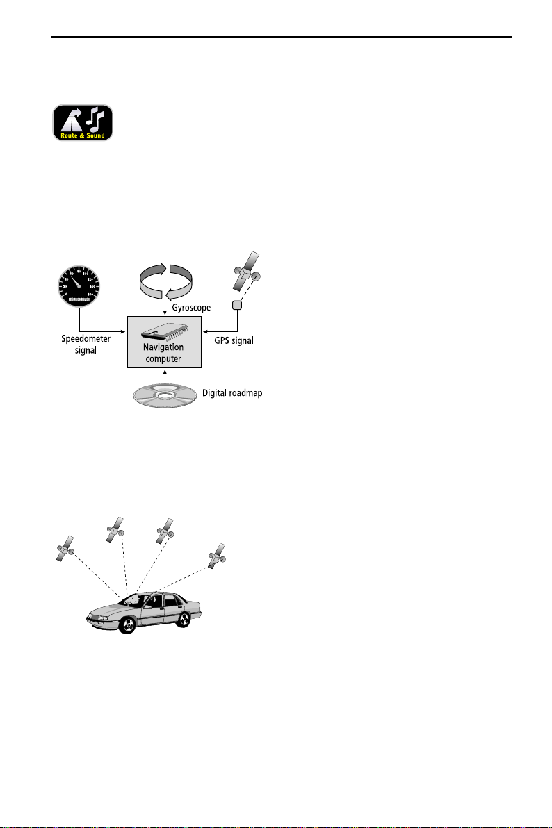
How does the navigation system work?
The position and movements of the vehicle
are recorded by the navigation system’s
sensors. The distance traveled is determined
by the vehicle speedometer signal, rotary
motion in curves is detected by a gyro sensor
(inertial compass). The position is determined
via the GPS (Global Positioning System)
satellites.
The position can be calculated within a range
of approx. 10 m by comparing the sensor
signals with the digital map on the
navigation CD.
Important notes on the function of your navigation radio
In principle, the system is functional with poor GPS reception, although the accuracy of
the positioning may be impaired by poor or interrupted GPS reception or errors can
occur in the determination of the position, which result in incorrect position reporting.
Start-up characteristics
If the vehicle is parked for longer periods of time,
the satellites continue their orbit. After the
ignition is switched on, it may take several
minutes until the navigation system receives
signals from sufficient satellites for evaluation.
During the start-up sequence, it is possible that the navigation system will report:
“You are leaving the digitized area”. The navigation system assumes that the vehicle is
located outside a digitized area. If other roads exist in this area, the navigation system
may issue incorrect messages. The navigation system assumes that the vehicle is located
on another road.
9
Page 13
GENERAL INFORMATION
Comments
After transport of the vehicle by train or ferry, the navigation system may require a
few minutes for exact positioning.
After disconnecting the vehicle battery, up to 15 minutes may be required for exact
positioning. For this, the vehicle must be outdoors and the system must be switched
on in order to receive transmissions from the GPS satellites.
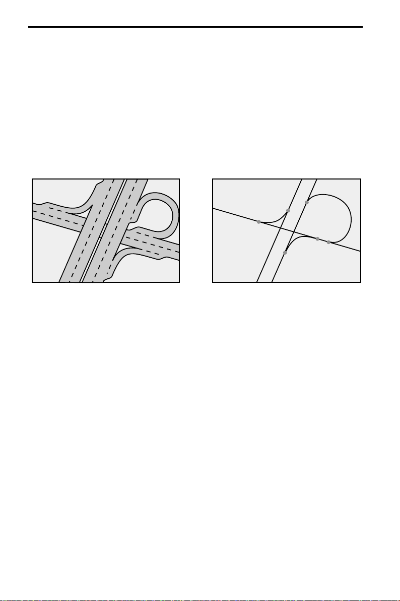
The digital road map
To be able to plan a route to a destination address, the navigation system not only
requires the current position of the vehicle but also a digital road map containing the
destination address itself and the roads leading to the destination address. This digital
road map is on the map CD which you insert into the navigation computer.
Real road network Digital line model
The road system is stored on the map CD as a line model, i.e. even large intersections
have only one focal point that is approached by all roads in point-to-point fashion.
Thus the navigation system indicates the distance to the turn-off point as the distance
to the center of the intersection. This is why the distances indicated on main road signs
may not agree with those of the navigation system. The road signs indicate the distance
to the beginning of the exit.
Areas with limited road information
In some areas, not all of the information on a road is available on the map CD. Thus,
for example, turn-off prohibitions, information on the direction of travel in a one-way
street or prohibited entry into a pedestrian zone may be missing. The navigation
system will display a warning if you drive into such an area. Local traffic laws always
take precedence over navigation system instructions. Always observe the road signs
and motor vehicle traffic regulations.
Topicality of the map CD
Roughly 10 - 15% of the road system characteristics change each year. Due to these
constantly changing traffic conditions (construction of new roads, traffic calming, etc.)
we cannot guarantee that the digital road map will be in 100 % agreement with
existing traffic conditions. We recommend that you always use the most current
version of the map CD for navigation.
10
Page 14

SAFETY
The system has the following safety functions to prevent theft:
Removable operating panel
Take the removable operating panel with you, whenever you leave the vehicle. Keep
the panel in its protective case. Always replace the operating panel before driving off.
When the front is opened, acoustic signals will sound (independent of the presence of
the removable operating panel).
Removing the operating panel
1. Openthe front by pressing the release button.
2. Pull the operating panel from its metal bracket.
3. Push the metal bracket back up.
Re-inserting control panel
1. Insert the operating panel with the right or the left side first.
2. Push the operating panel until it snaps into place.
To ensure a good connection between the device and the operating panel
we recommend that you clean the contacts occasionally with a cotton swab.
Security code
The navigation radio can be protected against theft with a security code. The unit is
disabled as soon as it is disconnected from the voltage supply (e.g. if it is stolen). It can
only be reactivated by entering the correct code.
The security code can be activated/deactivated and changed. For further information
see “INITIALIZATION”, option “Security Code” ➽ page 31.
Anti-theft protection LED
When the navigation radio is switched off and the ignition key removed, a red antitheft LED will flash on the front of the unit if the operating panel is removed.
The anti-theft LED is linked to the security code. It will not flash if the security code
has been deactivated.
CAUTION:
A
For reasons of safety please ensure that the removable operating panel is always flipped
up (closed) when driving.
11
Page 15
PREFACE
RDS (Radio Data System)
Many FM stations transmit RDS information. The navigation radio evaluates the
RDS telegram and offers the following advantages:
PS (Program Service Name): Display of station name,
–
–
PTY (Program TYpe): Station selection by program type, ➽ page 25
–
AF (Alternative Frequency): Automatic re-tuning to of best alternative frequency,
TA (Traffic Announcement): Traffic announcements , ➽ page 19
–
EON (Enhanced OtherNetworks): Automatic fading in of traffic announcements on
–
other stations, ➽ page 20
NEWS: Fading in of messages and items of news, ➽ page 19
–
Notes on audio CDs
You can play 12 cm audio CDs on your CD player. The use of 8 cm CDs (with or without
adapter) and of CDs with irregular shapes is not recommended.
Notes on map CDs
The navigation system is based on a C-IQ database, which is stored on a CD in encrypted
format. The CD contains map data for navigation as well as travel and traffic
information (TMC) for dynamic route planning. You can customize your navigation
package by activating specific components of the database.
TMC and dynamic route planning are not available in the U.S.
For further information see “C-IQ - INTELLIGENT CONTENT ON DEMAND”, ➽ page 32.
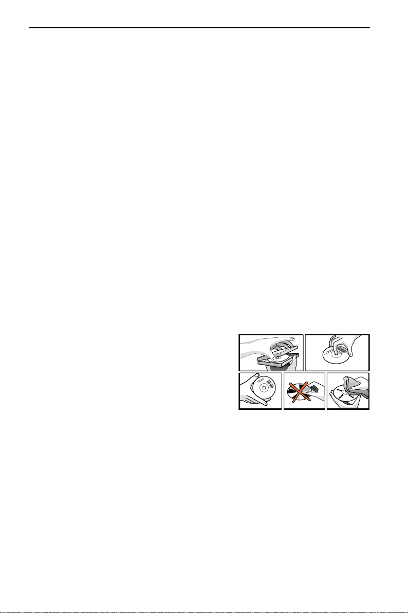
Handling CDs
Avoid leaving fingerprints on the CD when
removing it.
Always store map and audio CDs in their protective
covers.
Always ensure that CDs are clean and dry before
inserting.
Protect CDs from heat and direct sunlight.
12
r
e
d
ie
n
h
sc
n
te
h
c
ü
F
n
o
g
d
n
lf E
a
o
R
B
d
n
a
Page 16

OPERATION
Control elements
1 REL. . . . . . . . . Release button for removable control panel
2 VOL/POWER . . Press: On / Off
. . . . . . . . . . . . Turn: Setting the volume
3 TUNE . . . . . . . Radio mode. ➽ page 24
. . . . . . . . . . . . In radio mode: Opens the “RADIO” menu.
4 TEL . . . . . . . .With mobile telephone connected: Switch to telephone input
. . . . . . . . . . . . Without mobile telephone connected: Muting the system.
5 BAND . . . . . . . Opens the menu “BAND SELECTION” (in radio mode). ➽ page 23
6 SOUND . . . . . . Opens the “SOUND” menu. ➽ page 21
7 CDC . . . . . . . . CD changer mode. ➽ page 29
. . . . . . . . . . . . In CD changer mode: Opens the “CD CHANGER” menu.
8 CD . . . . . . . . . CD player mode. ➽ page 27
. . . . . . . . . . . . In CD player mode: Opens the “CD” menu.
9 . . . . . . . . . . . . Display
0 NAVIGATION . Opens the navigation menu. ➽ page 35.
q DEST/P.O.I.. . . Press once: Opens the list of addresses stored in the address book.
. . . . . . . . . . . . ➽ page 50.
. . . . . . . . . . . . Press twice in quick succession: Opens the “Info on car pos.” menu.
. . . . . . . . . . . . ➽ page 39.
w INFO. . . . . . . . Opens the “INFORMATION” menu. ➽ page 19.
e
{. . . . . . . . . . Play back current direction and (if available) the current TMC message.
. . . . . . . . . . . . ➽ pages 43, 44.
r 4 . . . . . . . . . . Moves the cursor to the left in the menus.
t 8. . . . . . . . . . Moves the cursor upwards in the menus.
z 2. . . . . . . . . . Moves the cursor downwards in the menus.
u OK . . . . . . . . . In menus: Confirms a selection.
. . . . . . . . . . . . For radio, CD player and CD changer: Switch search mode type.
i 6 . . . . . . . . . . Moves the cursor to the right in the menus.
13
Page 17
OPERATION
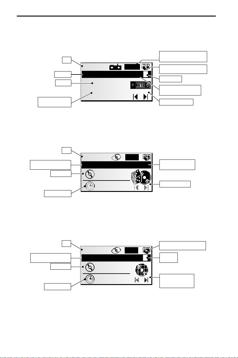
Displays
In radio mode:
Time
Waveb and
Frequency
Program (Station) name
(only with RDS stations)
In CD player mode:
Time
CD title (if entered)
With CD Text available:Artist
Tra ck nu mb er
Elapsed track time
13:29
t
RADIO 6FM DX
105.9
FFH
13:29
JIMMY HENDRIX Rnd.
x
T02
03:52
TA/TMC: Traffic Announcements /
TMC (see “INFORMATION” menu)
CD icon flashes: route is being
planned. Do not remove map CD!
Preset number
Selected search sensitivity
(for automatic search tuning)
Selected search mode
Rnd.
: Random playback
Rpt.
: Repeat track
Selected search mode
In CD changer mode:
Time
CD title (if entered)
With CD Text available:Artist
Tra ck nu mb er
Elapsed track time
10:44
x
ELVIS
T10
04:17
CD icon flashes: route is being
planned. Do not remove map CD!
Number of
4
selected CD
Selected search mode
or display for random
playback mode
In navigation mode:
The menus and displays for navigation mode appear in the “NAVIGATION” section.
14
Page 18
OPERATION
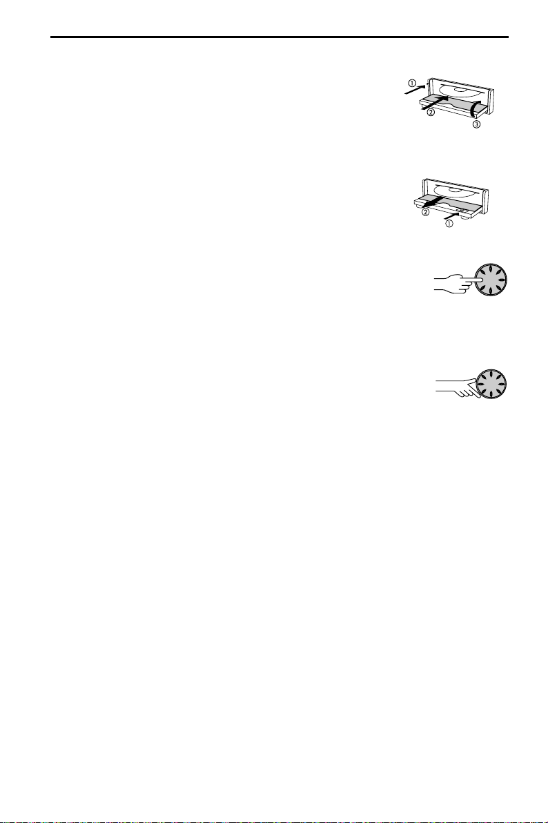
Inserting a CD
1. Open the front panel.
2. Insert the CD into the drive (printed side up).
For audio CDs, playback starts automatically.
3. Close the front panel.
Removing a CD
1. Press the eject button to open the front panel.
2. Carefully remove the CD and close the front panel.
Switching on / off
Press the VOL/POWER knob to switch the unit On or Off.
☞
Volume
A
When setting the volume, please make sure that traffic noises (horns, sirens, emergency
vehicles, etc.) are still audible.
Turn the VOL/POWER knob to set the volume.
☞
Setting the volume of the navigation messages
The volume of navigation messages can be modified whilst a message is playing by
turning the VOL/POWER knob.
Press the { button to hear a navigation message and set the NAV volume.
☞
Setting the volume of traffic announcements
The volume of traffic announcements can be set in the “INFORMATION” menu.
➽ page 19.
MUTE
Rapidly turn the VOL/POWER knob anti-clockwise to activate the mute function
☞
or:
Press the TEL button (only if there is no telephone connected to the unit).
☞
Notes:
The current navigation message can be played while the system is set to mute by
pressing the { button.
Traffic announcements will continue to play if the “TA Scan” option has been activated
in the info menu.
15
Page 19

OPERATION
Menu operation
Cursor
The currently selected line or field on the screen is
designated as the cursor. The cursor is identified by
an inverse field (bright letters on black background).
Move the cursor using the cursor buttons8, 2,
☞
4 or 6.
Confirm your selection by pressing the OK button.
☞
To confirm, the cursor will be displayed briefly as
:
a frame around the selected field.
Currently non-available options appear gray.
Scroll bar
All menusdisplay a scroll bar on the left side of the
screen. It shows the part of the menu in which to find
the cursor.
Move the cursor to a menu entry at the top or
☞
bottom of the screen using cursor button 8or 2.
Press the same button again.
☞
The screen automatically displays the next menu
:
items.
In all menus except the main menu, the menu title changes to the “Return” option
when you move the cursor to the top of the screen.
Confirm “Return” with the OK button to quit the menu
☞
Menu title
Active option 2
Active option 3
Active option 4
Active option 5
Return
Active option 1
Active option 2
Inactive option 3
Active option 4
or
press cursor button 8 again to move upwards in the menu.
☞
16
Page 20

OPERATION
Entering letters
Characters are entered by selecting letters from a list.
In the following, this type of entering will simply be
called “keyboard”.
Move the cursor using the cursor buttons 4, 6,
☞
8 and 2to the desired letter.
Confirm the selection by pressing OK.
☞
Non-selectable letters are displayed as dots and will
be passed over automatically by the cursor.
Options for entering characters
The line at the bottom of the display displays command symbols which allow you to
perform the following functions:
Y : Destination country selection (in this case, “USA” for the U.S.).
ƒ : Save an address in the personal address book.
‰ : Jump to menu “Points of interest”. See page 39.
¡ : Delete the character entered last.
Š : Direct input of road name without previously entering the name of the city
(depending on map CD).
© : Cancel entry and return to the start of the destination entry.
¯ : Display a list of database items.
® : End of destination input and automatic start of guidance.
– : Accept the data entries and go to the next input step.
o : Accept the data entries (e. g. when entering CD tracks).
Depending on information already entered, one or more options may not be selectable
(gray).
City:W_
A...E... .....O..
I
...U...Y...
¡‰
¯Z ®–
Intelligent “keyboard”
When you enter names of cities and roads or points of interest, the system compares
the character string already entered with all database entries on the map CD.
Once you select a character, you will notice that only certain letters remain displayed.
The Navigation Radio automatically completes entries if only one possible entry is left.
Different input methods
The database allows you to enter the different parts of compound city or road names
in varying sequence. If for example you want to enter “5 NORTH BEVERLY DRIVE” you
can start data entry with each of the name contents, for example “DRIVE” or
“NORTH”.
Entering special characters
The “keyboard” provides the space and the period and, depending upon the language
selected, certain country-specific accented characters.
17
Page 21

OPERATION
Normal and expert modes
With its radio, CD and CD changer modes, the unit offers two possible methods for
selecting the functions. You can choose between the “Expert” and “Common” modes.
The “Expert” mode reduces the number of operator steps when selecting search
functions. Instead of four buttons you need only use two to activate a function.
Choosing the user mode
Press the SOUNDbutton.
☞
Select option “Initialisation”.
☞
Select “User:” in the “Initialisation” menu.
☞
Select either “COMMON” or “EXPERT”.
☞
We will use the search function in radio mode to illustrate the difference between the
common and the expert mode:
Activating functions in common mode:
1. Press OK to call up the “SELECT MODE” menu.
2. 4 or 6 to select the search mode.
SELECT MODE
3. OK to confirm the selection.
4. 4 or 6 to start the selected search mode.
Activating functions in expert mode:
1. Press OK once or several times to select the search mode.
2. 4 or 6 to start the selected search mode.
Recall RDS Program
13:29
RADIOFM
105.9
Radio 1
18
Page 22

“INFORMATION” MENU
The “INFORMATION” menu
The “INFORMATION” menu allows you to configure the
type and amount of information the unit will
receive via the radio data system (RDS).
The RDS-based functions may not be available in
certain areas of the U.S.
Press the INFO button.
☞
The “INFORMATION” menu is displayed.
:
The following options are available:
TMC Scan (Traffic Message Channel)
If you activate this function, the automatic search will only look for stations
transmitting TMC information and will ensure that you receive as much TMC data as
the unit can find.
TMC data are used in navigation mode for dynamic route planning and dynamic
guidance. An increasing number of RDS stations transmit these TMC data. See also
“Behavior of TMC and TA” on the following page.
TMC is not yet available in all countries.
✎
TA Scan (Traffic Announcements)
Activate this function if you wish to hear traffic announcements (TA). See also “Behavior
of TMC and TA” on the following page.
If the radio has not been set to a station with TA, you will hear a warning tone and
✎
the radio will automatically search for a station transmitting traffic announcements.
News (NEWS)
Activate this function, if you wish to listen to news, e. g. even when a CD is playing or
when the unit is set to mute. Using the RDS-EON function, the unit can also receive the
news from other stations.
News broadcasts may be interrupted by traffic announcements.
✎
The “News” function is not yet available in all countries.
✎
Ann. level (Announcement level)
Set the volume difference for traffic announcements, news and alerts to the current
volume setting.
Guid. level (Guidance level)
Setting the guidance level controls the volume of announcements in navigation mode.
Possible settings range from OFF to 8. If it is set to “OFF”, no audible navigation
information will be heard. Switching the unit off and then on again removes this
setting and the value is reset to “1”.
INFORMATION
TMC Scan
TA Scan
News
Ann. level: 2
19
Page 23

“INFORMATION” MENU
Behavior of TMC and TA
If you switch on TMC Scan, you ensure that the radio will only search for stations
transmitting TMC data during the automatic search.
If the reception quality of the TMC station deteriorates drastically, the unit will indicate
this by outputting a warning message.
If you do not need guidance or are listening to an audio CD, yet you do not wish to go
without current traffic announcements, switch on the TA Scan function. In that case
the radio will play the traffic announcements even if it is in CD or CD changer mode or
muted.
Depending on the selected function and the station, the radio display will show the TA
or TMC status:
Station transmitting … Displayed message …
No TA No TMC – *
No TA TMC
TA No TMC
TA TMC
* In this case the unit will immediately start searching for the next strongest TA station
signal.
■
Traffic announcements from other stations – EON
With the RDS function EON (Enhanced Other Networks) you will hear traffic
announcements even if the set station does not transmit its own traffic information
but is operating on a network with other stations.
If you have activated TA Scan, stations with EON will be treated like TA stations, i.e.
the search will also stop at these stations.
When a traffic announcement is made, the unit switches to a traffic information
✎
station linked to EON. The program name of the traffic information station is
displayed during the traffic announcement. After the announcement, the unit
returns to the previous program.
TA Scan ON TMC Scan ON Both ON Both OFF
with setting in the “INFORMATION” menu:
u
y
x uu x
x t t t
t t t
– * No display
20
Page 24

The “SOUND” menu
In the “SOUND” menu, you can set your navigation
radio’s sound and several other sound reproduction
parameters to your own preferences.
The sound settings for bass and treble/tone are valid for
the currently active sound source (radio, CD or CDC).
Press the SOUND button.
☞
The “SOUND” menu is displayed.
:
The following options are available:
Sound settings
Set the desired option with cursor button8 or 2.
☞
Move the slide control to the desired option using
☞
cursor buttons 4 and 6.
The entered value will be stored automatically.
✎
Bass: Setting the bass (low tones).
–
Treble: Setting the treble (high tones).
–
Bal.: Setting of volume balance
–
Fader: Setting the volume distribution rear <–> front.
–
Sound settings cannot be performed for navigation information, traffic
✎
announcements and telephone operation.
left <–> right.
Slide control left: rear
Slide control right: front
Sound Settings
Loudness
Sound Style
SDVC: 2
SOUND SETTINGS
Bass
Treble
Balance
Fader
SOUND SETTINGS
SOUND
Loudness
Activate this function to increase low and high tones at low volume settings.
☞
Selecting one of the pre-set sound styles deactivates the loudness function.
✎
Sound Style
Select one of the pre-set sound styles.
☞
Select “User” to retain your own bass and treble settings.
☞
For each sound source, the sound style is stored separately.
✎
SDVC (speed-dependent volume control)
To compensate for environmental noise, the volume for audible information increases
as a function of the speed.
Choose a setting for the speed-dependent increase of the volume.
☞
Select OFF to deactivate the function or 1 ... 5 to choose the desired volume
☞
increase. 1 is the lowest, 5 the highest volume increase.
21
Page 25

SOUND SETTINGS
Sound Setup
Setting one of the following functions:
Sound Reset: Reset the sound setting to the factory-set values and switch off
–
Leveller: Activate this function to equalize volume differences between the
–
–
Loud Low: Set the enhancement of low tones at loudness.
Loud High: Set the enhancement of high tones at loudness.
–
Bass Freq: Select the transitional frequency for the low tones.
–
Treb Freq: Select the transitional frequency for the high tones.
–
Initialization
See “INITIALIZATION” ➽ page 30.
loudness.
various sound sources.
22
Page 26

Radio
Listening to radio
If the unit is not yet in radio mode:
Press the TUNE button.
☞
13:29
RADIOFM
105.9
Select waveband
In radio mode:
Press the BAND button.
☞
Select the desired waveband and press OK.
☞
The following wavebands are available:
✎
FM, FM AST (Autostore) AM, AM AST (Autostore). FM AST and
AM AST can only be stored with the Autostore function.
Setting stations
Stations can be set or sought in various manners (e.g. user mode “Expert”):
1. Press OK once or several times to select the search mode.
2. 4or 6 to start the selected search mode.
Recall RDS stations by name (only for FM)
The stations are sorted alphabetically.
If you hear an error message: Refresh the station name list by activating
“RDS Memo”. ➽ next page.
Automatic search
The radio searches for stations with strong signals.
If “TA Scan” is activated, the radio will search only for stations from
✎
which traffic announcements can be received.
If “TMC Scan” is activated, the radio will search only for stations from
✎
which traffic information can be received.
Radio 1
RADIO
Tuning to a stored station
Select one of the stations already stored manually or using Autostore.
Setting frequency manually
(if “Manual tuning” is activated. ➽ next page.)
After 50 seconds or after the selection of another tuning method, the radio
will switch back to automatic frequency tuning.
23
Page 27

RADIO
The “RADIO” menu
In radio mode:
Press the TUNE button.
☞
The “RADIO” menu is displayed.
:
The following functions are available:
RDS Memo (only on FM)
Searches for all currently available RDS stations and
stores them in alphabetic order.
Activate this function to refresh the RDS Memo.
☞
Refreshing the RDS Memo may require up to 30 seconds.
✎
Autostore
Activate this function to automatically store up to 10 FM/AM stations with strong
☞
signals on the FM AS or AM AS waveband.
Store Preset
Select the “Store Preset” function to add the currently selected station to the preset
☞
list. The storage function can store up to 30 stations.
This function is not available for the autostore wavebands FM AS and AM AS.
✎
Recall Program (only on FM)
Select a station from the alphabetically sorted stations list (RDS Memo).
☞
Recall Preset
Select a previously stored station from the preset list.
☞
Manual tuning
Activate this function to set a frequency manually, for example, if the desired station
☞
cannot be set using the automatic search function.
RDS Memo dyn.
When you are listening to a CD or when the radio is muted, it performs an automatic
search across the complete waveband range every 15 minutes and refreshes the RDS
Memo.
Activate this function in order to always have a current list of receivable RDS
☞
stations.
RADIO
RDS Memo
Autostore
Store Preset
Recall Program
Scan FREQ/PRST (Preview stations)
Activate this function in order to briefly play stations within the desired waveband.
☞
Press OK to cancel the scanning process and to listen to a station of your choice.
☞
The scan type (preset or frequency scan) can be set in the “Radio Setup” menu.
✎
➽ next page.
24
Page 28

Extra info
Display of information on the selected station:
recall number (if the station was stored),
–
station name (for RDS stations),
–
–
frequency,
–
program type (PTY, if the station transmits the PTY ID) and
the selected sound type for radio mode.
–
PTY search (only on FM)
This function allows you to search for stations of the desired program type.
Select the desired program type from the list.
☞
Press OK to start the PTY search.
☞
PTY is not supported by all RDS-stations and is not available in all countries.
✎
Radio Setup
Set one of the following functions.
☞
Search Level: Setting the search level.
–
Select “LO” if you want automatic waveband tuning to only search for local stations
(strong signals).
Select “DX” to also search for distant stations.
Tuner Grid: Select “EUR” or “USA” depending on which continent you are currently
–
in.
Scan Type: Select “FREQ” if all receivable stations on the current waveband are to be
–
scanned during station scan. Select “PRST” if only stored stations are to be scanned.
If you change the tuner grid, all station memories and the stations in RDS Memo will be
A
deleted!
RADIO
Initialization
See “INITIALIZATION” ➽ page 30.
25
Page 29

CD PLAYER
CD player
You can play 12 cm audio CDs on your CD player.
We strongly recommend only playing 12 cm CDs. Please do not use 8 cm CDs (neither
A
with nor without adapter).
ON NO ACCOUNT must unusually-shaped CDs be inserted into the player. If you ignore
A
these recommendations, you risk damaging your unit.
CD playback
If the unit is not yet in CD mode:
Press the CD button.
☞
Playback of the inserted CD will be continued at
:
the spot last played.
10:44
CD PLAYER Rnd.
T12
00:38
Selecting a function
Select one of the following CD player functions (e.g. user mode “Expert”):
1. Press OK once or several times to select the desired function.
2. Press 4 or 6 to execute the selected function.
Selecting a specific title (previous/next)
If you press 4 once after the first 10 seconds of a track, the CD player jumps
to the beginning of the current track.
x
26
Fast forward/backward search
Press OK to stop the fast search. When this function is executed, you will
hear the CD at increased speed.
Random play of tracks
The tracks on the inserted CD will be played in random order.
Page 30

CD PLAYER
The “CD” menu
In CD player mode :
Press the CD button.
☞
The “CD” menu is displayed.
:
Scan
Repeat Track
CD Title
Extra Info
The following functions are available:
Scan
Activate this function to briefly scan all tracks on the inserted CD.
☞
Press OK to cancel the scanning process and to listen to the track of your choice.
☞
Repeat Track
Activate this function to repeat the current track.
☞
Select “Repeat Track” again to deactivate the function.
☞
CD Title
Assign a name with up to 13 characters to the CD currently playing. The CD will be
☞
recognized automatically upon insertion, and the CD player will display the CD title.
If your CDs have CD text, you can also overwrite the CD title displayed.
✎
Up to 50 CD titles can be stored automatically in the title memory. Once the memory
✎
is full, you will have to first select a title to be deleted before you can enter a new
one.
CD
Extra info
Displaying information on the current CD:
CD title (if available),
–
–
total number of tracks,
–
total duration and
the selected sound type for CD mode.
–
CD Setup
Set one of the following functions.
☞
–
Compression: If activated, this function will reduce the volume for loud sections and
increase it for quieter sections.
Comp Rate: Select the degree of loudness decrease/increase when compression is
–
switched on.
Initialization
See “INITIALIZATION” ➽ page 30.
27
Page 31

CD CHANGER
CD changer (accessories)
A digital Jensen CD changer can be connected to the navigation radio.
We strongly recommend only playing 12 cm CDs. Please do not use 8 cm CDs (neither
A
with nor without adapter).
ON NO ACCOUNT must unusually-shaped CDs be inserted into the player. If you ignore
A
these recommendations, you risk damaging your unit.
A
Do not load navigation CDs into the CD changer.
CD changer playback
If the unit is not yet in CD changer mode:
Press the CDC button.
☞
Playback of the last played CD resumes.
:
If you changed or removed the CD magazine in
✎
the meantime, playback will begin with the first
CD in the magazine.
CD CHANGER
T10
04:17
Selecting a function
Select one of the following CD changer functions (e.g. operating mode: “Expert”):
1. Press OK once or several times to select the desired function.
2. Press 4 or 6 to execute the selected function.
Selecting a CD
Choose one of the CDs in the CD magazine.
TA10:44
x
4
28
Selecting a specific title (previous/next)
If you press 4 once after the first 10 seconds of a track, the CD player jumps
to the beginning of the current track.
Fast forward/backward search
Press OK to stop the fast search. When this function is executed, you will
hear the CD at increased speed.
Page 32

CD CHANGER
The “CD CHANGER” menu
In CD changer mode:
Press the CDC button.
☞
The “CD CHANGER” menu is displayed.
:
The following functions are available:
Scan
Activate this function to briefly scan all tracks on the currently selected CD.
☞
Press OK to cancel the scanning process and to listen to the track of your choice.
☞
Random
Activate this function to listen to the tracks on the currently selected CD in random
☞
order.
Repeat Track
Activate this function to repeat the current track.
☞
Select “Repeat Track” again to deactivate the function.
☞
Select CD
Select the desired CD from the list.
☞
CD Title
Assign a name with up to 13 characters to the CD currently playing. The CD will be
☞
recognized automatically by the CD changer, and the CD changer will display the
CD title.
If your CDs have CD text, you can also overwrite the CD title displayed.
✎
Up to 50 CD titles can be stored automatically in the title memory. Once the memory
✎
is full, you will have to first select a title to be deleted before you can enter a new
one.
CD Changer Setup:
Set one of the following functions.
☞
Compression: If activated, this function will reduce the volume for loud sections and
–
increase it for quieter sections.
Comp Rate: Select the degree of loudness decrease/increase. This function is only
–
available with compression activated.
–
CD Access: Indicate if you want to choose the CD in the menu “Select CD” by
number or by title.
CD CHANGER
Scan
Random
Repeat Track
Select CD
Extra info
Displaying information on the currently selected CD:
–
Number of the selected CD (in magazine),
–
CD title (if available),
total number of tracks,
–
total duration and
–
the selected sound type for CD changer mode.
–
Initialization
See “INITIALIZATION” ➽ page 30.
29
Page 33

INITIALIZATION
The “INITIALIZATION” menu
Select “Initialisation” in one of the following
☞
menus: “RADIO”, “INFORMATION”, “CD” or “CD
CHANGER”.
The “INITIALISATION” menu is displayed.
:
The “INITIALISATION” menu allows you to adjust
the navigation radio to your needs.
The following functions are available:
Telephone
Adapt your unit’s telephone input to your car phone:
☞
NONE: No car phone is connected to the unit.
–
MUTE: Playback on the current source is automatically interrupted when your car
–
phone is in use. For this purpose, the car phone’s muting signal must be connected
to the device (see installation instructions).
–
IN: Playback on the current source is automatically interrupted and the incoming
call is played through the car loudspeakers. For this purpose, the car phone’s muting
signal and audio output must be connected to the device (see installation instructions).
Tel Signal:
Adapt your unit’s telephone input to the muting signal of your car phone:
☞
–
LOW: Muting signal “active low”. Radio switches to mute at 0 V.
–
HIGH: Muting signal “active high”. Radio switches to mute at 12 V.
Tel. Level:
Adapt the car phone’s volume to the navigation radio’s telephone input.
☞
The volume adjustment can be set to between -30 and +30.
✎
Beep Type
Select a confirmation/alert sound. You have the choice between 4 different sounds.
☞
Beep Level:
Set a level between 1 and 5 for the confirmation/alert sound.
☞
Clock Settings
Setting the time, the time format and the time zone:
–
Clock Type: Select either RDS or GPS.
With GPS, the time of day is received via the Global Positioning System in UTC.
With RDS, the time is synchronized with the data of the currently received RDS
station (the time signal transmitted by the RDS stations may be incorrect).
–
Clock Format: Select between 12 or 24 hour format.
Timezone (only for GPS clock): Set the time difference to UTC (equivalent to
–
Greenwich Mean Time, London).
Scan time
Setting for the scan time for frequency, storage or track scanning.
Choose 5, 10 or 15 seconds.
☞
INITIALISATION
Beep Level: 1
Clock Settings
Scan Time: 15s
On Off Logic
30
Page 34

INITIALISATION
On Off Logic
Activate this function to limit the operation of the device to one hour after the
☞
ignition key is removed.
Display
Setting the display contrast and display brightness (day and night settings).
Set the required contrast and brightness for the display in order to optimize the
☞
legibility of the text in accordance with lighting conditions.
The brightness night setting can only be applied if the vehicle lighting has been
✎
switched on (see also installation instructions).
User
Setting the user mode for radio, CD and CD changer.
Select either “COMMON” or “EXPERT”.
☞
Icons
Choose either “STATIC” (immovable) or “ANIMATED” (moving) symbols for operation
☞
of the radio or another sound source.
Loudspeaker Test
Activate this function to control the loudspeaker connections and positions.
☞
You will hear several consecutive confirmation tones in turn from one of the four
✎
loudspeakers.
Switch the unit off to terminate the loudspeaker test.
☞
Security Code
In the factory settings, the security code is deactivated and set to “0000". You can
activate the code and change the numbers.
Proceed as follows to enter the security code:
Enter the first digits using the 8 and 2 cursor keys and confirm by pressing OK.
☞
Enter the next three digits as described above.
☞
If you enter and confirm an incorrect digit, you must enter the entire code again
✎
from scratch.
The unit will be disabled once ten incorrect codes have been entered. The unit can
✎
only be reactivated by taking it to a Service department along with proof of purchase.
This service is subject to a fee.
Code active
■
Activate this function if you wish to protect the device with the security code.
☞
If the power supply is interrupted (e.g. if the unit is removed), the navigation radio
✎
will be disabled once the supply is restored and can only be reactivated by entering
the security code.
If the security code has been activated, when the ignition key is removed, the anti-
✎
theft LED will flash on the front of the unit if the operating panel is removed.
■
Change code
Enter a sequence of digits of your choice as the new security code.
☞
Make a note of the code and keep it in a safe place (not in the vehicle!).
☞
31
Page 35

C-IQ – INTELLIGENT CONTENT ON DEMAND
C-IQ – Your key to map, traffic and travel information
Your navigation radio is supplied with a CD containing the latest version of the map
software along with travel and traffic information (for dynamic navigation). The
information on the CD is encrypted and can be partially or completely activated for a
defined period with the aid of an access code. Your advantages:
–
You only pay for the information that you actually use.
–
You only pay for the time that you actually use.
After the first activation, you will automatically receive subsequent CD updates.
–
You always have the latest information.
–
You can obtain the activation easily via the Internet, by calling our free hotline or
–
from your dealer.
Activation options
The CD contains the latest version of the road map software. It also contains travel
guide information for a number of countries as well as traffic information for dynamic
route planning via TMC (in countries which offer this service).
You can activate
–
the road data
–
individual travel guides and if required
traffic information
–
in a number of countries for a certain period of time (see also the preview in this
chapter). Your C-IQ Service will be happy to provide more information about the
possible access options. You should also read the C-IQ brochure supplied with your
map CD.
TMC and dynamic route planning are not available in the U.S.
✎
Registering the navigation system
In order to activate C-IQ products, you must register your navigation system with C-IQ
Service. Registering the system also provides you with additional anti-theft protection.
If a unit is registered with C-IQ Service as stolen, C-IQ Service will not issue any new
activation codes for C-IQ contents.
To register your navigation system, you need the Navi ID. In a small number of cases
the Initial ID or version number of your map software is also required.
You can access this data as follows:
Press the NAVIGATION key.
☞
In the main menu, select “C-IQ”.
☞
Select “Navi ID”.
☞
The 8-digit Navi ID, the map CD currently loaded
:
and the version number of the navigation
software are displayed.
To read out the Initial ID, move the cursor to
☞
“Initial ID” and confirm your selection by
pressing OK.
The “Z” symbol will take you back to the previous menu and you can access help
✎
for the current C-IQ topic by selecting “?”.
Make a note of the Navi ID. You can now contact C-IQ Service and register your system.
☞
32
Navi ID: 8Q6S 7ED4
CD EUR 2003/01 NT
SW ID: 0046
Navi ID
Initial IDZ ?
Page 36

C-IQ – INTELLIGENT CONTENT ON DEMAND
Activating products
Once you have received your enable code, enter it
into the system.
In the main control menu, select “C-IQ” then
☞
“Code Input”.
The cursor appears automatically on the first digit
☞
of the code.
Press OK to activate each digit in the code.
☞
Next, use the cursor keys to select the correct code digit and confirm your selection
☞
by pressing OK.
You may change any of the code digits at any time by moving the cursor to the
✎
required position in the code and pressing OK.
Once the code is complete, the cursor will automatically move to “OK”. Confirm by
☞
pressing OK.
Once you have entered a correct code, the system will display information about
☞
the C-IQ products you have just activated.
The system will inform you if an incorrect code has been entered, and/or if your system
✎
software is not capable of processing the encrypted information.
In these cases, select either “OK”or “C-IQ Service”, if you wish to establish contact,
☞
and press the OK key.
It is possible to operate the system without activation. Destinations can be entered.
Navigation information, however, will only be provided for activated areas and for
activated services.
Code Input
8QR5-Z4AK
G __-____6
OK Quit ?
My C-IQ
You have the choice of obtaining information about your activation status at any
time.
Select “My C-IQ” in the “C-IQ” menu.
☞
Select “Active products” if you wish to find out more about the products you
☞
have activated.
Select “Starting soon” if you wish to view details of products you have received
☞
which will soon be active.
Select “Expiring soon” if you wish to find out which service products you currently
☞
have in use and for how long they will continue to be available.
Select “Revocated products” to view a list of products which have been revocated.
☞
33
Page 37

C-IQ – INTELLIGENT CONTENT ON DEMAND
Preview
Together with your map and travel information software you will also receive the
opportunity to inspect different products free of charge before ordering them.
You can have the system display the status of this preview:
Select “Preview” in the “C-IQ” menu.
☞
You will see the status of your preview options. It contains the number of map and
:
travel information products that you are still able to test free of charge.
You can access a list of possible preview products via the L symbol.
☞
Select the product you require from the list in order to test it for the period of time
☞
indicated.
C-IQ Settings
Set up your system so that you are informed about the status of your activated C-IQ
products automatically and in good time:
Select “C-IQ Settings” in the ”C-IQ” menu.
☞
Select the number of days (between 1 and 10) you wish to be informed in advance
☞
of the expiry or start of the products you have activated.
You can use “Expiring soon” and “Starting soon” to select whether you wish to
☞
be informed in advance and, if so, which products you wish to be informed about.
Select “Return” to go back to the previous menu.
☞
If you wish to be informed about the expiry or start of C-IQ products when the system
✎
starts up, you can view a list of corresponding products via the L symbol.
C-IQ Info
Here you will find general information about the C-IQ products on the map CD you
have loaded.
Select “C-IQ Info” in the “C-IQ” menu.
☞
This option is only supported by certain map CDs.
✎
C-IQ Service
Here you will find information about your C-IQ Service:
Select “C-IQ Service” in the ”C-IQ" menu.
☞
Select “Z” to go back to the previous menu.
☞
Select “P C-IQ” to establish telephone contact with the C-IQ Service Center.
☞
The “P C-IQ” option is only active if a telephone module is connected to the
✎
navigation system (this function is in preparation).
34
Page 38

NAVIGATION
Main menu
A map CD must be inserted into the CD player for some of the functions in navigation
mode.
If the unit is not yet in navigation mode:
Press the NAVIGATION button.
☞
The navigation main menu is displayed.
:
The following items are available in the main menu:
Destination input
Opens the “Destination input” menu. Here, a
destination address can be entered for guidance.
See page 36.
Viapoint input
Opens the “Via point input” menu. Here via points (stops) can be entered on your
way to the destination address. See page 41.
Guidance
This option provides access to the guidance screen and activates the guidance
function. Additionally, access to various information screens such as current car
position, trip computer, or the list of via points is available. See page 43.
Traffic info
This feature is not available in the U.S.
Address manager
Opens the “Address manager” menu. The address manager enables management of
frequently used addresses for destinations and via points. See page 50.
C-IQ
Use this option to manage your C-IQ data. See page 32.
Emergency
Opens the “Emergency” menu. Here, information on the current position of the car
and geographic position (GPS position) is obtained. See page 52.
Main menu
Destination input
Via point input
Guidance
Traffic info
Stop guidance
Use this option to switch off the navigation display and the audible information. The
system’s navigation functions remain active in the background.
Press the NAVIGATION button to reactivate the navigation.
☞
Settings
Opens the “System Settings” menu. In this menu, many navigation settings can be
customized. See page 53.
Games
Pass the time with one of the available games. (For your safety, of course, only when
the vehicle is stationary.)
35
Page 39

NAVIGATION
Destination input
Destinations may be entered in several ways:
–
Entering city, road and house number or crossroads by means of the “keyboard.”
See the following page.
–
Loading an address stored in the personal address book. See page 50.
–
Recall one of the last 20 addresses used for guidance.
Selecting a specific destination (e. g. hotel, gas station, train station) from the
–
database on the map CD. See page 39.
–
Entering the geographic coordinates (GPS position) directly, e. g. when the
destination is not on a digitized street. See page 40.
–
Transferring a destination from the travel guide information (if you have enabled
C-IQ Travel Info data).
Destination input menu
In the main menu, select “Destination input”.
☞
The “Destination input” menu is displayed.
:
In the destination input menu, the following choices
are available:
New address
Input country, city, road, house number or
intersection or even a point of interest.
Destination input
New address
Load address
Last destin.
Info on car pos.
Load address
Loading an address stored in the address book.
Press theDEST/P.O.I. button once briefly to load an address from one of the “Private”
☞
or “Business” address books.
Use “Home” or “Work” to load the address stored in this memory location and
✎
activate guidance immediately.
Last destination (Last destin)
Load one of the last 20 addresses used for guidance.
Info on car position (Last pos)
Loading a special facility (POI = Point of Interest) in the vicinity of the current position
of the car (depending on the loaded map CD, hotels, restaurants, gas stations, rest
stops, garages, etc. may be available for this purpose).
Long-/Latitude
Entering a destination by means of GPS coordinates (geographic latitude and longitude).
Travel info
If you have enabled a C-IQ Travel Info product (e.g. Varta, Michelin, etc.) you can search
specifically for particular facilities and transfer them directly as the destination. Detailed
information about advanced search options can be found in the Travel Info brochure
supplied with the map CD.
36
Page 40

NAVIGATION
Entering a new address
An input wizard will help you enter a new address. It will lead you step by step
through all the necessary entries such as country, city, road, house number or
crossroads and required routing criterion.
Step 1: City or zip code
Select ”New address” in the destination input menu.
☞
The display automatically shows “City:” and the
:
keyboard window, the name of the last
destination city is already displayed.
If you want to enter a destination address in the
☞
city shown, simply select “–”.
or:
Enter a new city name or zip code via the
☞
“keyboard”.
or:
Select the ¯ list symbol and choose an entry in the database.
☞
If several database entries have the same name, the cursor automatically moves to
✎
the ¯ symbol. Select the required entry type from the list.
If there is a large number of possible entries, it may take several seconds to build
✎
the list.
Confirm your selection with “–”.
☞
Change country
■
The currently selected country appears as a country code in the bottom left of the
✎
keyboard window when a city is entered.
If you wish to change the destination country,
☞
move the cursor to the country code and confirm
your entry.
The list of countries stored on the current map CD
:
appears.
Countries not currently activated appear in “< >”.
✎
Select the required country from the list.
☞
You can also enter destinations in countries which have not been activated. You
✎
will then only receive directions until you reach the border of that country.
Quick Access (to destination addresses via road names)
■
This function is particularly useful for reducing the input time for unusual road names.
If the loaded map CD supports this function, the quick access symbol Š will appear in
the window for entering the city name.
Select the Š symbol in the keyboard window.
☞
Once the complete road name has been entered, only the initial letters of the cities
:
in which a road with that name is located will appear in the keyboard window.
If necessary, you should now enter the required city name and confirm your entry
☞
with “–”.
City:W_
A...E... .....O..
I
...U...Y...
¡‰
¯Z ®–
Country
<FRANCE>
<ITALIA>
<UNITED KINGDOM>
UNITED STATES
37
Page 41

NAVIGATION
2. Step: Road
Once the city has been entered the input wizard automatically jumps to the
:
“Road:” input menu.
Enter the name of the road using the “keyboard” or select a name from the list
☞
using ¯.
3. Step: House number or intersection
If house numbers are available for a selected road, they can be entered with a separate
input menu. If no house numbers are available, the system automatically jumps to the
“Intersection” input menu.
If no intersection is available, this step will be skipped.
After confirming the road name with “–”, the input menu for the house number
:
or intersection appears.
Enter the required house number or intersection.
☞
Within the database, certain ranges of house numbers are combined, the entered
✎
house number being in such a range. In such a case, the navigation system will lead
you to the entered house number range.
In some cases, the navigation system will also correct your entry. If for example you
✎
have entered house number 83 but only numbers up to 51 are stored on the map
CD, the system will automatically correct this to 51.
4. Step: Route selection
The required criterion for route planning can be modified even after all data for the
destination has been entered.
A detailed description of the route criteria can be found under “Route selection” on
page 46.
Once the route criteria are selected, the system jumps to the guidance screen and
begins planning the route. Within only a few seconds you will begin to receive
guidance information.
Directly to guidance
While using the input wizard, you can, at any time, jump to guidance, e.g. if certain
information on the destination address is unavailable (house number, crossroads) or if
you wish to be guided to the city or town limits only. In that case, proceed as follows:
Enter at least the name of a city as described earlier.
☞
After input, select the ® symbol in the lower line of the input menu.
☞
The guidance screen appears.
:
The route is being planned.
✎
For further information about guidance, see the chapter entitled “Guidance” on
page 43.
38
Page 42

NAVIGATION
Points of interest (POIs)
You may also input the destination address by selecting special facilities (POI = Points
of Interest) stored in the database. These include e.g.:
airports,
–
–
hotels,
–
gas station,
car repair garages
–
public parking, etc.
–
Depending upon the information already entered in the destination input screen, a list
of general interest facilities appears which are is present on the current map CD.
Special facilities of national importance
Select “New address” and use the input wizard to select the required country.
☞
Then, select the ‰ symbol in the lower line of the input menu.
☞
A list of the categories of points of national interest is shown.
:
Select the required category (e.g. AIRPORT, FERRY…).
☞
If more than four facilities are stored for the selected category, the “keyboard” will
:
be displayed.
For up to four stored facilities, the list will appear immediately.
✎
Enter the name of the required facility or select the ¯ symbol for the list display.
☞
Confirm the input using “–” or select an entry from the list.
☞
Special facilities in connection with the destination
Select “New address” and use the input wizard to enter the required country and
☞
the name of the required destination.
Then, select the ‰ symbol in the lower line of the input menu.
☞
A list of categories of special facilities is shown.
:
For smaller towns, it may be that only the “CITY CENTER” option is available. If you
✎
select this option, the navigation system will guide you to the city center.
Select the required category (e.g. HOTEL, GAS STATION…).
☞
If more than four facilities are stored for the selected category, the “keyboard” will
:
be displayed.
For up to four stored facilities, the list will appear immediately.
✎
Enter the name of the required facility or select the ¯ symbol for the list display.
☞
Confirm the input using “–” or select an entry from the list.
☞
39
Page 43

NAVIGATION
Special facilities in the vicinity of the current position
You may also set a destination address by selecting a special facility in the vicinity of
the current vehicle location.
Briefly press the DEST/P.O.I. button twice
☞
or:
Select “Info on car pos.” in the destination input menu.
☞
A list of categories of special facilities is shown.
:
Select the required category.
☞
A list of facilities pertaining to the selected
:
category, located in the vicinity of the current
vehicle location, appears. Additionally, distance
and direction to the facilities are shown.
Proceed as described on the previous page.
☞
Train station
AMTRAK SACRAMENTO
17 km
AMTRAK SUISUN CIT
26 km
Note:
You will always see a list of facilities from “Info on car pos.”, even if there is no
facility from the selected category directly at the car position.
The facilities list is sorted by distance to the car position, i.e. the facility closest to the
car position will be first in the list.
Destination input via GPS coordinates
If you know the GPS coordinates of a destination, you
may enter them directly.
In the main menu, select “Destination input.
☞
Select “Long-/Latitude” in the “Destination
☞
input” menu.
The GPS coordinates input menu appears.
:
Mark the required coordinate using the cursor
☞
keys. Then press OK.
Next, set the required values for degrees, minutes, seconds and north/south or
☞
east/west using the cursor keys. Confirm the destination input with “OK”.
The navigation system compares the GPS coordinates you entered with the data on
:
the current map CD and plans the route.
Long-/Latitude
115°09'43" West
36°14'21" North
OK
Quit
Notes:
If the destination is beyond the digitized roads, the system will guide you along
digitized roads as far as possible. The system will then display the linear direction
and the distance to the destination.
If the GPS coordinates you entered should be outside the limits of the current map CD,
the system will display an error message.
40
Page 44

NAVIGATION
Via point input
If you wish to visit other locations en route to the
entered destination address, these can be stored as
via points. The navigation system then plans the route
to include the via points in the given sequence before
the destination address is reached.
When you reach a via point, you will hear “you have
arrived.” The navigation system will immediately begin
to plan the route to the next via point or the final
destination.
In the address manager or on the “Via points” information screen you can delete via
points you have not reached yet or which you do not wish to visit any longer.
See page 48 or 50.
In the main menu, select “Via point input.”
☞
The “Via point input” menu appears.
:
The following options are available in the “Via point input” menu:
New address
Input country, city, road, number or crossroads or special facility as via point.
Load address
Loading an address stored in the address book as a via point.
Last destination (Last destin)
Recall one of the 10 addresses last used for guidance to load as a via point.
Info on car position (Last pos)
Loading a special facility in the vicinity of the current position of the car.
Long-/Latitude
Entering a destination by means of GPS coordinates (geographic latitude and longitude).
Travel info
If you have enabled a C-IQ Travel Info product (e.g. Varta, Michelin, etc.) you can search
specifically for particular facilities and transfer them directly as the via point. Detailed
information about advanced search options can be found in the Travel Info brochure
supplied with the map CD.
Via point input
New address
Load address
Last destin.
Info on car pos.
The input of a via point is identical to the input of a destination address.
41
Page 45

NAVIGATION
Delete via points not reached
Via point which you have not reached or which are no longer desirable to you must be
deleted from the via point list so that the navigation system may plan the route to the
next via point or to the final destination. If a not reached via point is not deleted, the
system will continue to try and guide you to this via point.
Via points can be deleted in the address manager or on the “Via points” information
screen, see page 50 or page 48.
Notes:
The maximum number of stored via points is 25.
The via points are targeted in the order in which they are entered.
For guidance to the via points, the system automatically uses the route planning
criterion for the final destination.
It is possible to enter new via points en route to the final destination at any time.
Once a via point has been reached (“destination reached”), it is deleted from the list
of via points.
If you enter a new destination you will be asked whether you also wish to delete the
via point list. If you answer “No,”the remaining via points will be retained for the new
destination address.
Via points are not stored in the list of last destinations (destination input and viapoint
input).
Via points cannot be stored with “Store address”in the address manager.
42
Page 46

NAVIGATION
Guidance
The guidance screen appears as soon as you activate the guidance.
The guidance screen displays the following information:
5
6
7
8
9
1 Road direction arrow: The arrow indicates the course of the road.
2 Simplified presentation of the next turn-off prompt.
3 Turn-off prompt: A graphic display of the next crossroads or intersection. In
addition, directional changes are announced with audible messages.
4 CD symbol
Flashing black: The navigation computer is loading map data for the navigation
corridor. The map CD must not be removed during this time.
Flashing gray: Please insert the map CD (the navigation computer needs to reload
the map data).
5 Road into which to turn at the next announcement.
6 You are in an area with incomplete map information.
7 Distance to the next change in direction.*
8 Option field. Move the cursor to the required symbol and confirm:
Z : Return to the main menu
ª : To “Alternative route” menu. ➽ page 49.
U : Display and select route criterion. ➽ page 46.
I : To information screens. ➽ page 47.
9 Status field. Display of the following possible information:
– Remaining driving distance
– Remaining travel time
– Estimated time of arrival
– Current time
You can configure the status field in the “System settings” menu. See page 54.
!
Main St
400 ft
5,6 km
ªªZ
2:45 pm
IU
W Abberton Bl
2,6 mls
Z
36 mls
4:36 pm
IU
4
3
2
1
* Units displayed are dependent upon the system configuration. Refer to page 53,
chapter “System settings.”
43
Page 47

NAVIGATION
Audible messages
During guidance, the navigation radio will provide acoustic routing information in
addition to the symbols on the guidance screen. Commonly, the directive to turn into
another road consists of two voice messages:
an early warning
e.g. “Right turn ahead”
W CHEYENNE AVE
1.5 mls
6,5mls
and
the instruction to turn
e.g. “In 400 feet turn right”
“Turn now” advice
In addition to information regarding turning, the system also provides “turn now”
advice, which is output directly at the turnoff point.
The “turn now” advice can be deactivated in the “System settings –> Language”
✎
menu.
Improved acoustic guidance information
In many countries, “speaking” road signs are available for main road slip roads (e.g.:
“Take exit number 7 and follow the B 429").
Repeating voice message
Did you miss the last guidance message or didn’t you fully understand it?
Press the { button.
☞
You will hear the current guidance message.
:
Did you ignore the last message?
If you did not follow the last guidance message or if you were not able to follow it
due to traffic conditions (road works, etc.), the system will, within a few seconds, plan
a new route from the current position of your car to your destination.
ªZ
02:45
IU
W CHEYENNE AVE
400 ft
4,1mls
ªZ
02:45
IU
44
Page 48

NAVIGATION
On longer route segments without intersections or
crossroads, an arrow is displayed indicating the course
of the road over the next 300 ft. In addition, a
reduced diagram of the next turn-off prompt appears
on the left, above the route direction arrow. Thus,
the driver is always warned in advance of the next
change of direction.
Shortly before the change of direction, the detailed
turn-off prompt appears.
AVORY DRV
2.8 mls
ª
4,1mls
Z
02:45pm
IU
Guidance beyond digitized roads
If you leave a digitized road, the arrow pointing to
the nearest digitized road will appear automatically.
If that is the case, continue in the direction of the
☞
arrow until you reach a digitized road.
As soon as you return to a digitized road, you will
receive destination guidance again.
6 mls
15 mls
ªZ
11:27am
IU
Areas with limited road information
In some areas, not all of the information on a road is available on the map CD. Thus,
for example, turn-off prohibitions, information on the direction of travel in a one-way
street or prohibited entry into a pedestrian zone may be missing. The navigation radio
will display a warning if you drive into such an area. Local traffic laws always take
precedence over navigation system instructions.
At the top left of the guidance screen, you will see the ! symbol, as long as you are in
an area with limited road information.
Always observe the road signs and motor vehicle traffic regulations.
A
45
Page 49

NAVIGATION
Route selection
During guidance, you may also modify the route criterion and activate or deactivate
dynamic route planning. The system will then plan a new route taking into account
the new setting of the current position of your car.
In the guidance screen, select the symbol for route selection (on the basis of the
☞
setting in the destination input U, V, W or X).
The following options are available:
Dynamic route: This option is not available in the U.S.
–
–
Fast: If you prefer a fast route
–
Short: If you prefer a short route
Main roads: If you prefer expressways
–
No main roads: Avoids expressways
–
In addition, you can bypass toll roads when planning your route.
Activate the “Minimize tolls” option if you wish to avoid toll roads as much as
☞
possible.
If no toll-free roads are available, toll roads will be included for planning the route.
✎
Note: If this option is activated, route planning may take longer than the time needed
with this function deactivated. Therefore this option should only be activated if needed.
46
Page 50

NAVIGATION
Information during guidance
During guidance, you can call up several information
screens:
Move the cursor to the ™ symbol and confirm by
☞
pressing OK.
The list of information menus appears.
☞
The following information menus are available:
Route list
This option is available as soon as a route has been
planned.
The list of segments of the planned route appears.
Confirm the required entry by pressing OK in order
☞
to view the complete road name.
Select “Return” to quit the road list.
☞
Event on the route (this feature is not available in the U.S.)
This information menu is only available if the radio is receiving a station transmitting
traffic information and if one or more traffic obstructions are reported on your route.
A list of segments for which traffic obstructions have been reported appears. The list is
sorted on the basis of the location of each obstruction on the route.
Select a report in order to access detailed information about the traffic obstruction.
☞
Car position
Display of current vehicle location with country code,
city, road, and, if available, house number.
If you are located beyond a digitized road, the screen
will display the GPS position (geographic longitude
and latitude).
The GPS position can be accessed at any time via
✎
the “Emergency” option in the main menu.
Travel data
Route list
Event on the route
Destination
Via points
Route list
B277 0.5 mls
B49 0.3 mls
Ab Anschl 0.7 mls
A45 18.8 mls
Return
USA
NORTH LAS VEGAS
N MARTIN L KING BL
47
Page 51

NAVIGATION
Displaying / deleting via points
If via points have been entered for the current
destination, the “Via points” option will be active.
The number of via points still to be reached also
appears.
Select the required via point from the list in order
☞
to view details or delete it.
Destination
Display of current destination address with Name (if
entered), country code, city, road, and crossroads.
GPS / Compass
Display of the following information:
1. GPS reception status: Displays the number of GPS
satellites received. With an unobstructed view of
the sky, up to 8 satellites may be displayed.
2. Current driving direction (compass). The arrow
always points north.
3. Date and time
Via points
CHICAGO >
TROY >
Return
DOROTHY
USA
LOS ANGELES
S FETTERLY AVE
EAST LOS ANGELES M
Return
7
04/02/03 8:12 am
Trip computer
The following information appears in the
“Trip computer” information menu:
Current speed
–
Average speed
–
Maximum speed so far
–
–
Distance traveled
–
Time traveled
■
Resetting values:
Confirm O by pressing OK.
☞
Confirm the deletion with “Yes”.
☞
All trip computer values are reset to zero.
☞
■
Speed warning:
You can enter a speed above which an alarm will sound. To set the speed limit, see
“Speed” on page 53.
48
Trip computer
35 mph
24 mph
96 mph
235 mls
Page 52

NAVIGATION
Alternative route
During guidance, you can cause the navigation system to plan an alternative route.
Use this function if, for example, you want to avoid stationary traffic reported via
traffic announcements or if you wish to plan an alternative route.
The alternative route will be calculated for a selectable distance from the current
position of the car.
Move the cursor to the ª symbol in the guidance
☞
screen and confirm by pressing OK.
If you agree with the displayed distance, confirm
☞
with “OK”.
The system is planning an alternative route for the
:
entered distance. A details screen will soon appear
(diversion, time delay/saving).
Confirm the planned alternative route with “Yes”
☞
or reject it with “No”.
If you reject the alternative route, the navigation
✎
system will plan a new route to the destination
from the current position of the car.
The display shows the guidance screen again.
:
Cancel procedure
Move the cursor to “Quit” and press OK.
☞
Change distance
If you wish to change the distance displayed, proceed as follows:
Move the cursor to the displayed distance.
☞
Press OK.
☞
Change the displayed distance in the range of 1 to 6 miles using cursor keys 4 or 6.
☞
Press OK again.
☞
The cursor is set on “OK”.
:
Confirm with “OK”.
☞
The system will suggest an alternative route for the planned trip as described
✎
above.
Alternative route
6 mls
OK Quit
Alternative route
Distance: +5.0 mls
Time: +13 min
Accept alteration?
Yes No
49
Page 53

NAVIGATION
Address manager
The navigation radio offers the opportunity of storing at least 30 destination addresses
in a personal address book. In the address book, you can store your destinations
separately under the categories “Private” and “Business”. The “Home” and “Work”
shortcuts, which can be programmed with your home address and business address
respectively, are also available here.
Select the “Address manager” in the main menu
☞
and confirm the selection.
The address manager is displayed.
:
The following options are available:
Storing addresses in the address book
If you have not yet entered a destination address:
Enter the data of the required destination address (city, road, crossroads or special
☞
facility) into the destination menu.
In the main menu, select the “Address manager” option.
☞
Next, select “Store address”.
☞
Select which address books the address should be stored in (private, business, home
☞
or work).
The name input menu appears.
:
Using the “keyboard,” enter any string of up to 15 characters as the name for the
☞
address. Complete the input with “o”.
If you do not wish to enter a name, select “o” directly.
✎
The address is now stored in the selected address book.
:
Delete address
Addresses that are no longer needed should be deleted from the address book to
ensure sufficient space for new addresses.
Select “Delete address” in the address manager.
☞
Select which address book the address should be deleted from (private, business,
☞
home or work).
A list of the destination addresses stored in the selected address book is displayed.
:
Select an address to be deleted from the list and confirm your selection.
☞
The selected address is deleted from the address book.
:
Delete via points
If via points have been entered for the current destination, you can display the via
point list and delete via points from it.
Select “Delete via points” in the address manager.
☞
A list of the stored via points appears.
:
Select a via point to be deleted from the list and confirm your selection.
☞
The selected via point is deleted.
:
Via points can also be deleted in the “Via points” information menu, see page 248.
✎
Address manager
Store address
Delete address
Delete via points
Store current loc.
50
Page 54

NAVIGATION
Store current loc.
Would you like to store a favorite restaurant in the destination memory? You can store
the current position of your car as follows:
Select “Store current loc.” in the address manager.
☞
Select which address books the address should be stored in (private, business, home
☞
or work).
The name input menu appears.
:
Enter a name and complete the input with “o”.
☞
If you do not wish to enter a name, select “o” directly.
✎
The current position of the car is stored as an address in the selected address book.
:
Deleting list of last destinations
Select “Delete last dest.” in the address manager.
☞
The list of destinations last used for guidance is displayed.
:
Renaming addresses
If you wish to change the name of a destination address, select the “Rename address”
option in the address manager.
Select which address book the address should be edited in (private, business, home
☞
or work).
Select the address to be edited from the list and enter a new name for it.
☞
Confirm your entry with “o”.
☞
The address will be stored under the new name in the address book.
✎
Comments:
30 entries is the guaranteed minimum of entries for the address book. This total can
be up to 200, depending on the data entered (e.g. with or without a name, etc.)
If there is no address in the address book, the “Delete address” option cannot be
selected.
If no via points have been entered for the current destination, the “Delete via
points” option cannot be selected.
Once the address book is full, the “Store address” and “Store current loc.” options
will no longer be available.
51
Page 55

NAVIGATION
Emergency menu
In the main menu, select “Emergency”.
☞
The “Emergency” menu is displayed.
:
The following options are available in the
“Emergency” menu:
GPS position
Display of the current geographic vehicle location as calculated by the Global Positioning
System. Longitude, altitude and elevation above sea level (provided adequate GPS
reception is available) will be displayed.
Car position
Display of current vehicle location with country code, city and street. This option is
only available if you are on a digitized road.
Emergency
GPS position
Car position
52
Page 56

NAVIGATION
System settings
To customise the navigation functions to your own
needs, you can change several settings.
In the main menu, select “Settings”.
☞
The “System settings” menu is displayed.
:
The following information screens are available:
Speed
In the “Speed” menu, you can configure the following settings:
Speed correction
The navigation radio uses an average cruising speed to calculate the remaining travel
time and the estimated time of arrival. If required, you can adapt this speed to your
actual average speed.
However, we do not recommend you deviate significantly from the standard value of
100%.
Move the cursor to the value after “Correction”.
☞
Press OK.
☞
Set the required speed correction using cursor keys 4 or 6.
☞
To save the setting press OK again.
☞
Speed limit
Use this value to specify the vehicle speed at which a speed warning should be output.
Move the cursor to the value after “Limit (mph)”.
☞
Press OK.
☞
Set the required speed using cursor keys 4 or 6.
☞
To save the setting press OK again.
☞
Activating/deactivating speed warning:
Move the cursor to the option after “Limit:”.
☞
Press OK to choose between “On” and “Off”.
☞
If the speed warning is activated, a warning sound is triggered each time the set
✎
speed limit is exceeded and a warning appears on the screen.
System settings
Speed
Guidance screen
Dyn. route sett.
Language
53
Page 57

NAVIGATION
Guidance screen
Here you can select the information which should appear on the guidance screen.
Show event
■
Select whether traffic obstructions on your route should appear in the top line of
☞
the guidance screen or not.
This feature is not available in the U.S.
✎
Remain. distance
■
Select whether the distance-to-go to the destination or via point should appear in
☞
the status field of the guidance screen or not.
Times
■
Select which times should appear in the status field of the guidance screen. The
☞
following options are available:
Time of arrival
–
Remaining time
–
–
Current time
–
No time display
Dyn. route sett.
Settings for dynamic route planning
This feature is not available in the U.S.
✎
Language
Choose one of the two languages loaded in the system,
☞
or:
Select “Other language” to replace one of the two loaded languages with another
☞
language from the system software CD (included).
Select the language to be replaced.
☞
You will be prompted to insert the software CD.
:
Insert the language CD in the CD player of the radio.
☞
Follow the system instructions for loading other languages.
☞
Turn now advice
■
If this option is activated, an additional prompt (e.g. “Now turn right”) will be output
directly before a turn-off
This prompt is activated by default.
✎
Measuring units
Choose between the following units of measurement for distance:
☞
Metric: Display in kilometers and meters.
–
Anglo: Display in miles and yards.
–
American: Display in miles, half and quarter miles and feet.
–
54
Page 58

NAVIGATION
Default settings
Select this option in order to reset all user-defined settings to their default values. All
entries in the address book will remain stored.
Mounting angle
To adapt the navigation computer to the mounting angle of the radio in the dashboard
(gyro-sensor compensation). This adjustment need only be made once after the
installation of the radio. See “Setting the installation angle”, ➽ page 7.
Service
For diagnosing hardware and software problems (code-protected).
The option “Service” is exclusively reserved for service work on the navigation radio
performed by an authorized service company.
System Info
The “System Info” menu displays information about the software and hardware version
(for service purposes).
55
Page 59

NAVIGATION
Loading software updates
In order to extend the range of functions provided by the unit, you can load new
software versions from a software update CD, if available for your navigation radio:
Switch on the radio.
☞
Open the front and remove the CD if still inserted.
☞
Insert the software update CD into the CD player.
☞
A safety check appears. Confirm the check with “Yes,” if you want to overwrite the
☞
existing operating software.
The new operating software is then loaded automatically. The loading progress is
:
indicated by a bar.
On no account must the ignition or radio be switched off during the loading procedure,
A
even if no displays appear on the monitor for a while.
Once loading is complete, you will be prompted to remove the software update CD.
:
Please confirm the completion of the loading procedure with “OK”.
☞
The radio will then switch itself off automatically.
:
Wait approx. 1 minute before switching the radio back on.
☞
The navigation radio is now ready for operation with the new operating software.
✎
You may need to change the system language according to your requirements.
✎
56
Page 60

TROUBLESHOOTING
Troubleshooting
In rare instances, your navigation radio may not function the way you expect it to.
Before calling for technical assistance, please read the operating instructions
thoroughly and go through the following check list; it may be possible to quickly
remedy an apparent malfunction.
Symptoms Possible cause / remedy
General
Navigation radio not functioning. No display. • Check the fuse (unit and vehicle) and the connections (see installation
Audio or map CD rejected by the unit. The CD may be dirty.
System switches off the sound during driving or
display shows “PHONE IN/MUTE”.
The removable part of the unit feels warm. No error. The unit always generates some heat.
The display shows “Temperature too high” and
the volume is lowered.
The egg timer appears and the CD cannot be
ejected.
The telephone is not being detected even
though it has been connected to the radio.
Unit not functioning / Not suitable for VW/Audi
vehicles
Display still showing “INIT”. Will not function. The unit is faulty.
Radio
Poor radio reception. • Check if the antenna is completely extended and correctly connected.
The display shows the frequency instead of the
station name.
The required station cannot be set with
automatic search.
The display shows “Tune to next TA station”
and a warning tone sounds.
No traffic announcements are being made
(CD, CDC or MUTE).
CD player / CD changer
Distorted sound / skips during CD play. Player cannot read CD. CD is damaged or soiled.
CD player does not work. In cold weather conditions, condensation may occur on the laser.
No sound during CD play. Some CDs contain multimedia data which is not recognized by the unit.
Problems with new copy-protected audio CDs. Some copy protection procedures are incompatible with accepted standards for
instructions).
• Clean the CD with a special CD cleaning fluid.
Speedometer signal connected to the wrong pin of the power supply
connector.
• See pin setting ISO chamber A in the installation instructions.
An integrated safety circuit prevents the temperature in the unit from
exceeding a certain value.
• Allow the unit to cool (set lower volume) and wait until “Temperature too
high” disappears from the display.
• Disconnect the power supply from the unit for at least one minute then
reconnect it. If this does not work, return the unit to the Service department.
• Call up the initialization menu, select “Telephone ON” and select “12 V” for
Nokia hands-free units.
The power supply connector pin assignment for VW and Audi is not the same.
• Use the VDO Dayton MA1910 adapter for the connection.
• Take it to the Service department.
• Verify that the supply power negative pole (brown lead) is correctly
connected to earth (vehicle chassis).
If the unit is being installed in VW and Audi vehicles, you will need a power
supply adapter for the antenna.
• Use a suitable adapter (e.g. Votex).
The unit is set to a station that does not transmit RDS signals or the
transmitter is too weak.
The required station is too weak.
• Set required station manually (manual tuning).
• Check if the antenna is completely extended and correctly connected.
“TA Scan” or “TMC Scan” has been activated
The radio only tunes to stations with traffic news or TMC information.
• You may need to deactivate the “TA Scan” or “TMC Scan” function.
Tuner standard (tuner grid) wrongly set (EUR / USA).
• Check the “Tuner Grid:” option in the “Radio” menu.
“TA Scan” is switched on, the selected station, however, is too weak or does
not transmit traffic announcements (TA).
• Deactivate the “TA Scan” function or set another station.
• Activate the “TA Scan” function in the “Information” menu.
• Wait approximately 5 minutes until the condensation evaporates.
• Select the next track until music is heard.
audio CDs. This is not a fault on the unit.
57
Page 61

TROUBLESHOOTING
Symptoms Possible cause / remedy
Navigation
Display shows “Please insert map CD”. The map CD is required for some functions in navigation mode and for route
System reacts very slowly to entries or requires
a long time for calculation.
Only some of the options are available in the
main menu.
The number of satellites in the
“GPS / Compass” information menu is 0.
The directions cannot be heard or are very
quiet.
Address cannot be stored in the address book. Address book full.
Guidance is not accurate. An inaccuracy of approx. 30 m is within the tolerance limits.
Displayed position does not correspond to
actual vehicle position.
Directions do not correspond to the actual
traffic conditions.
The time in the “GPS / Compass” information
menu is incorrect.
Estimated time of arrival displayed on the
guidance screen is incorrect.
C-IQ
During guidance, no traffic information is
displayed, even though the selected radio
station is transmitting TMC data.
No more directions shortly after crossing the
border. Only the direction arrow is appearing in
the guidance screen.
Display shows “Please insert correct CD”. • Check that you have inserted a map CD which contains C-IQ data. Map CDs
planning.
• Insert the C-IQ map CD into the radio CD drive with the label facing
upwards.
You are in a very densely digitized area. The system requires more time to read
large data quantities.
• Insert the map CD.
• Ensure that the GPS antenna is not being obstructed by any objects.
• Move the vehicle outdoors if you are in a garage, a car park or a tunnel.
• Press the Info button and set the required Nav volume.
• Delete one or more no longer required entries from the address book.
• Please contact your authorized dealer if greater inaccuracies frequently occur.
The displayed distance to the turning point is calculated to the center of the
intersection (especially for extended intersections and main road exits).
Bad GPS reception for an extended period (e.g. as a result of poor reception
conditions). The position is corrected automatically when adequate GPS
reception returns.
• If necessary wait a few minutes.,
It is possible that the car position calculated by the navigation system is
incorrect at this instant.
The routing may have been changed and does not correspond with the
information stored on the map CD.
• Set the correct time zone in the “INITIALISATION – CLOCK SETTINGS” menu.
• Check the time zone in the “INITIALISATION - CLOCK SETTINGS” menu
(if GPS clock is set).
You do not have a C-IQ Traffic info product activated.
• Contact C-IQ service to activate C-IQ Traffic info contents.
You are travelling in a country for which you do not have activated C-IQ map
contents.
• Contact C-IQ Service to activate map data for the required country.
without C-IQ will not be accepted by the system.
Specifications subject to change without notice.
58
Page 62

WARRANTY
12-Month Limited Warranty
AUDIOVOX CORPORATION (the Company) warrants to the original retail purchaser of this
product that should this product or any part thereof, under normal use and conditions, be
proven defective in material or workmanship within 12 months from the date of original
purchase, such defect(s) will be repaired or replaced with new or reconditioned product (at the
Company's option) without charge for parts and repair labor. To obtain repair or replacement
within the terms of this Warranty, the product is to be delivered with proof of warranty coverage
(e.g. dated bill of sale), specification of defect(s), transportation prepaid, to the warranty center
at the address shown below.
This Warranty does not extend to the elimination of car static or motor noise, to correction of
antenna problems, to costs incurred for installation, removal, or reinstallation of the product, or
damage to tapes, compact discs, accessories, or vehicle electrical systems. This Warranty
does not apply to any product or part thereof which, in the opinion of the Company, has suffered
or been damaged through alteration, improper installation, mishandling, misuse, neglect,
accident, or by removal or defacement of the factory serial number/bar code label(s) or
markings. THE EXTENT OF THE COMPANY'S LIABILITY UNDER THIS WARRANTY IS
LIMITED TO THE REPAIR OR REPLACEMENT PROVIDED ABOVE AND, IN NO EVENT,
SHALL THE COMPANY'S LIABILITY EXCEED THE PURCHASE PRICE PAID BY
PURCHASER FOR THE PRODUCT.
This Warranty is in lieu of all other express warranties or liabilities. ANY IMPLIED
WARRANTIES, INCLUDING ANY IMPLIED WARRANTY OF MERCHANTABILITY, SHALL BE
LIMITED TO THE DURATION OF THIS WRITTEN WARRANTY. ANY ACTION FOR BREACH
OF ANY WARRANTY HEREUNDER INCLUDING ANY IMPLIED WARRANTY OF
MERCHANTABILITY MUST BE BROUGHT WITHIN A PERIOD OF 30 MONTHS FROM DATE
OF ORIGINAL PURCHASE. IN NO CASE SHALL THE COMPANY BE LIABLE FOR ANY
CONSEQUENTIAL OR INCIDENTAL DAMAGES FOR BREACH OF THIS OR ANY OTHER
WARRANTY, EXPRESS OR IMPLIED, WHATSOEVER. No person or representative is
authorized to assume for the Company any liability other than expressed herein in connection
with the sale of this product.
Some states do not allow limitations on how long an implied warranty lasts or the exclusion or
limitation of incidental or consequential damage so the above limitations or exclusions may not
apply to you. This Warranty gives you specific legal rights and you may also have other rights
which vary from state to state.
U.S.A: Audiovox Corporation, 150 Marcus Blvd., Hauppauge, NY 11788, 1-800-323-4815
CANADA: Call 1-800-323-4815 for location of warranty station serving your area.
59
Page 63

SPECIFICATIONS
CEA Power Ratings
Power Output: 13 watts RMS X 4 channels into 4-ohms @ < 1% THD+N
Signal to Noise Ratio @ 1kHz: 70dBA below reference. (Reference: 1 watt, 4-ohms)
Dynamic Power: 26 watts @ 4-ohms x 4 channels
Frequency Response: 20Hz to 20kHz (-3dB)
Reference Supply Voltage: 14.4VDC
CD Player
Signal to Noise Ratio @ 1kHz: >100dBA
Frequency Response: 20Hz to 20kHz, -3dB
Channel Separation @ 1kHz: > 68dB
D/A converter: 1Bit/Ch
FM Tuner
Tuning Range: 87.5MHz - 107.9MHz
Mono Sensitivity (-30dB): 12dBf
Quieting Sensitivity (-50dB): 18dBf
Signal to Noise @ 1kHz: >70dB
Stereo Separation @ 1kHz: >25dB
Frequency Response: 40Hz to 15kHz, -3dB
AM Tuner
Tuning Range: 530kHz - 1710kHz
Sensitivity (-20dB): 30uV
Signal to Noise @ 1kHz: 65dB
Frequency Response: 40Hz - 2kHz, -3dB
EIAJ Amplifier Output (PEAK)
Total System Power: 160 watts PEAK
Power Output: 40 watts X 4 PEAK
Speaker Impedance: 4-ohms
Reference Supply Voltage: 14.4VDC
General
Power Supply: 11 to 16VDC, negative ground
Fuse: 15 amp, ATO
Wire harness: ISO-DIN Euro quick-disconnect harness
DIN chassis dimensions: 7" X 7" X 2" (178mm x 178mm x 51mm
60
Page 64

Page 65

v.033104
 Loading...