

Page 1
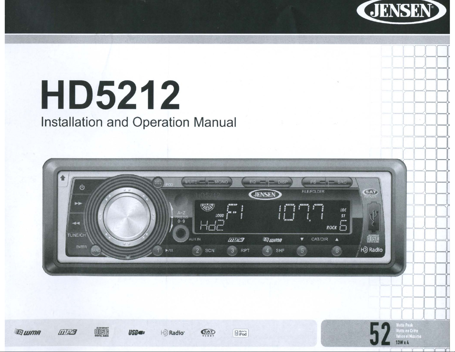
HD5212
Installation
and
Operation
Manual
DO[
{j8
t!lm
--
Radio·
Page 2
HD5212
~
TABLE
Introduction
Preparation
Wiring
Installation
Front
Panel
Operation
Tuner
Satellite
CD Player
MP3/WMA
iPod
Operation
Remote
Care
and
Troubleshooting
Specifications
OF
Release 7
Operation
Radio
Operation
Operation
Control
Maintenance 24
CONTENTS
Operation
1
2
3
4
8
11
13
15
17
21
23
25
26
Page 3
HD5212
&,
Introduction
Congratulations on your purchaseofthe Jensen HD5212 Mobile Receiver.
of
It's a good idea to read all
installation. We recommend having your Jensen HD5212 installed by a
reputable installation shop.
Features
Built in HD Radio™ Tuner*
Made for iPod
XM and Sirius Satellite Radio Ready
MP31
Supports
24 Station Presets (18 FMI 6 AM)
Electronic Detachable Faceplate
Rear Pre-amp Line Output
2MB ESP
Last Position Memory
Random, Repeat, Intro
LCD Dimmer
Preset EQ- Rock, Pop, Classic
Loudness
Electronic Bass, Treble, Balance, Fader
jLink iPod Cable and 3.5mm Media Adapter Cables Included
Infrared remote control
WMA
the instructions before beginning the
files via CD- R/RW, SD card, or USB
~
TM
*HD Radio
Corp. U.S. and Foreign Patents.
proprietary trademarks
Technology Manufactured Under License From iBiquity Digital
of
iBiquity Digital Corp.
HD
Radio™ and the HD Radio logo are
1
Page 4
~
Preparation
HD5212
Tools
The following tools and supplies are needed to install the radio.
SPEAKER REQUIREMENTS:
impedance
ohms
Disconnecting
To
negative (-) battery cable prior to installation.
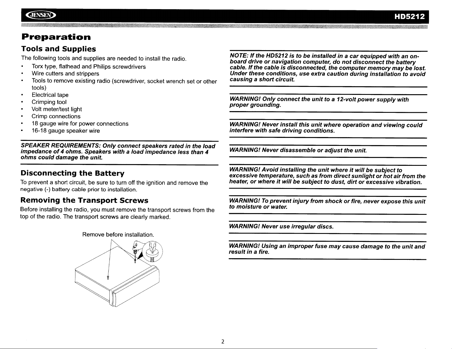
Removing
Before installing the radio, you must remove the transport screws from the
top ofthe radio. The transport screws are clearly marked.
and
Torx type, flathead and Philips screwdrivers
Wire cutters and strippers
Tools to remove existing radio (screwdriver, socket wrench set or other
tools)
Electrical tape
Crimping tool
Volt meter/test light
Crimp connections
18
gauge wire for power connections
16-18 gauge speaker wire
could
prevent a short circuit, be sure to turn off the ignition and remove the
Supplies
of4ohms.
damage
the
Only
connect
Speakers
the unit.
the
Battery
Transport
Remove before installation.
withaload
Screws
speakers
impedance
ratedinthe
less
than
load
4
NOTE:Ifthe HD5212
board
cable.Ifthe cableisdisconnected,
Under
causingashort
WARNING!
proper
WARNING! Never
interfere
WARNING!
WARNING!
excessive
heater,
WARNING!
to
WARNING!
driveornavigation
these
conditions,
Only
grounding.
with
safe
Never
Avoid
temperature,
or
whereitwillbesubject
To
prevent
moistureorwater.
Never
istobe
circuit.
connect
install
driving
disassembleoradjust
installing
injury
use
irregular
installed
computer,donot
use extra
the
unit
this
unit
conditions.
the
unit
suchasfrom
from
discs.
inacar
the
computer
caution
to a
12-volt
where
operation
whereitwillbesubject
direct
to dust,
shockorfire,
equipped
disconnect
memory
during
the unit.
sunlightorhot
dirtorexcessive
installationtoavoid
power
and
never
withanon-
the
supply
viewing
expose
battery
may
be lost.
with
could
to
air
from
vibration.
this
the
unit
WARNING!
result
2
Usinganimproper
in
a fire.
fuse
may
cause
damagetothe
unit
and
Page 5
HD5212
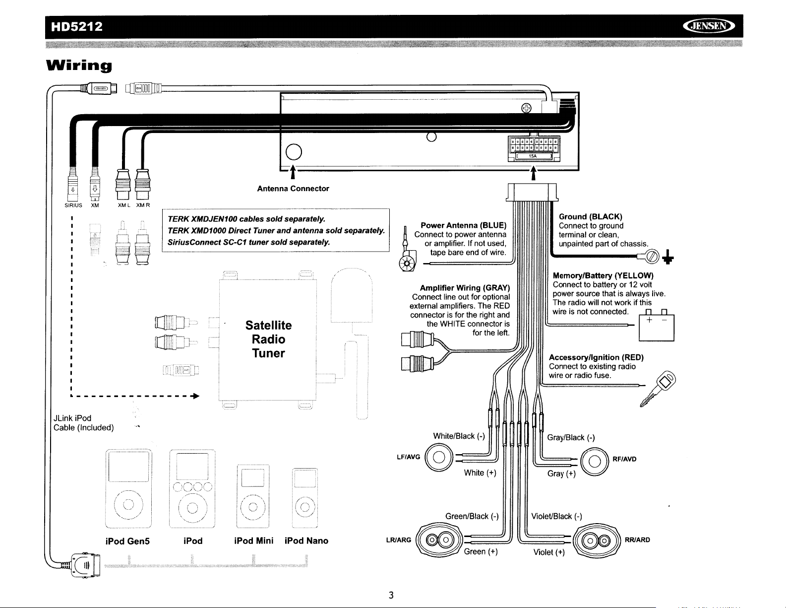
Wiring
~
SIRIUS
~I
XM
XML
XMR
t-L--------------
Antenna Connector
TERK XMDJEN100 cables sold separately.
TERK XMD1000 Direct Tuner
SiriusConnect SC-C1 tuner
,;fO
',-
.
'1'''1
!'_.,
.!:I
..•
1
rr:IJ
Satellite
and
sold
separately.
Radio
Tuner
antenna sold separately.
._._..--_
.....
-----------=l
Power Antenna (BLUE)
Connect to powerantenna
or amplifier. If not used,
tape bare end
~
*
Amplifier Wiring (GRAY)
Connect line out for optional
external amplifiers. The RED
connector is for the right and
the WHITE connector
for the
1SA
t
Ground (BLACK)
Connect to ground
terminal
or
of
wire.
is
left
unpainted partofchassis.
~--~@
Memory/Battery (YELLOW)
Connect to battery or 12 volt
power source that is always live.
The radio will not work if this
wire is not connected.
Accessoryngnition (RED)
Connect to existing radio
w;"
o"ad;o
clean,
",e.
..
~
U
-r
---------------+
JUnk
iPod
Cable (Included)
\.~'::""
White/Black (-)
Gray/Black (-)
LFIAVG@~
White (+)
Green/Black (-) Violet/Black (-)
iPod
Mini
iPodiPod GenS
iPod Nano
lRIAOG @
3
G~reen
(2J+)
~G~r~ay~(+::)
~V~iolet~(+)
@OFlAVO
0
8
"<AOO
Page 6
~
Installation
This unit is designed for installation in cars, trucks and vans with an existing
radio opening. In many cases, a special installation kit will be required to
mount the radio into the dashboard. These kits are available at electronics
supply stores and car stereo specialty shops. Always check the kit
application before purchasing to make sure the kit works with your vehicle.
or
Ifyou have trouble locating a kit
Technical Support at 1-800-323-4815 from 9:00am to 6:00pm EST Monday
through Friday.
Universal
1.
Remove the detachable front panel,ifit is attached to the chassis, by
pushing the "Release" button.
2. Slide the mounting sleeve off
removed.
disengage
3.
Check the dashboard opening size by sliding the mounting sleeve into
it.Ifthe opening is not large enough, carefully cut or file as necessary
until the sleeve easily slides into the opening. Do not force the sleeve
into the opening
sufficient space behind the dashboard for the radio chassis.
4.
Locate the series of bend tabs along the top, bottom and sidesofthe
mounting sleeve. With the sleeve fully inserted into the dashboard
opening, bend as many
secure the sleeve to the dashboard.
Installation
Ifitis
locked into position, use the removal keys (supplied) to
it.
The removal keys are depicted on page
or
cause it to bend or bow. Check that there will be
of
need installation assistance, contact
Using
of
the chassis if it has not already been
the tabs outward as necessary to firmly
Mounting
Sleeve
6.
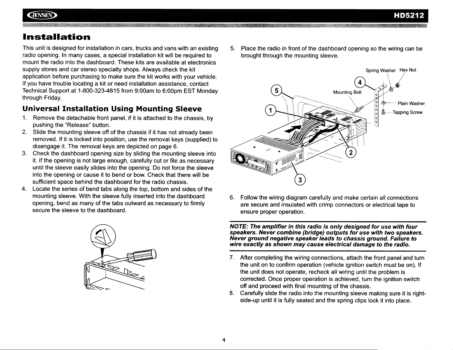
5.
Place the radioinfrontofthe dashboard opening so the wiring can
brought through the mounting sleeve.
&--
6.
Follow the wiring diagram carefully and make certain all connections
are secure and insulated with crimp connectors or electrical tape to
ensure proper operation.
HD5212
be
Plain Washer
Tapping Screw
NOTE: The
speakers. Never
Never
wire
7.
8.
4
ground
exactlyasshown
After completing the wiring connections, attach the front panel and turn
the unit on to confirm operation (vehicle ignition switch must be on). If
the unit does not operate, recheck all wiring until the problem is
corrected. Once proper operation is achieved, turn the ignition switch
off and proceed with final mounting
Carefully slide the radio into the mounting sleeve making sure it is rightside-up until it
amplifierinthis
combine
negative
speaker
may
is
fully seated and the spring clips lock it into place.
radioisonly
(bridge)
cause
outputs
leadstochassis
electrical
designed
for
damagetothe radio.
of
the chassis.
for
use
use
with
two speakers.
ground. Failure
with
four
to
Page 7
HD5212
9.
Attach one endofthe perforated support strap (supplied) to the screw
on
stud
other end of the perforated strap to a secure part
either above or below the radio using the tapping screw and washer
provided. Bend the strap, as necessary, to position it. CAUTION: The
rear of the radio must
the dashboard from the weight
vibration. The strap also ensures proper electrical grounding
10. Re-attach the front panel to the chassis and test radio operation by
referring to the operating instructions for the unit.
the rearofthe chassis using the hex nut provided. Fasten the
of
the dashboard
be
supported with the strap to prevent damage to
of
the radio or improper operation due to
of
the unit.
~
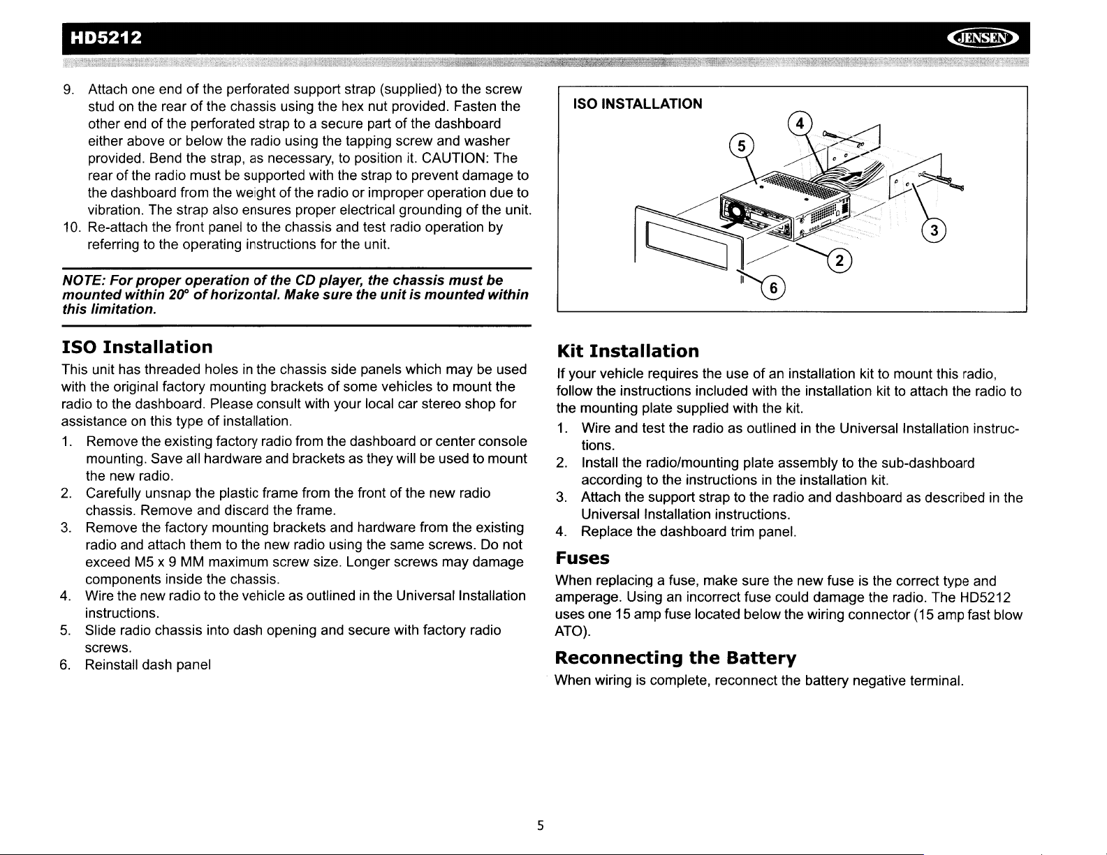
ISO INSTALLATION
NOTE:
mounted
this limitation.
ISO
This unit has threaded holesinthe chassis side panels which maybeused
with the original factory mounting brackets
radio to the dashboard. Please consult with your local car stereo shop for
assistance
1.
2.
3.
4.
5.
6.
For
proper
within
operationofthe
2(1'
of
horizontal. Make
CD
player, the
sure
chassis
the
unitismounted
must
be
within
Installation
of
some vehicles to mount the
on
this type of installation.
Remove the existing factory radio from the dashboard or center console
mounting. Save all hardware and brackets as they will be used to mount
the new radio.
Carefully unsnap the plastic frame from the frontofthe new radio
chassis. Remove and discard the frame.
Remove the factory mounting brackets and hardware from the existing
radio and attach them to the new radio using the same screws. Do not
exceed M5 x 9 MM maximum screw size. Longer screws may damage
components inside the chassis.
Wire the new radio to the vehicle as outlinedinthe Universal Installation
instructions.
Slide radio chassis into dash opening and secure with factory radio
screws.
Reinstall dash panel
Kit
Installation
If
your vehicle requires the useofan installation kit to mount this radio,
follow the instructions included with the installation kit to attach the radio to
the mounting plate supplied with the kit.
1.
Wire and test the radio as outlinedinthe Universal Installation instructions.
2.
Install the radio/mounting plate assembly to the sub-dashboard
in
according to the instructions
3. Attach the support strap to the radio and dashboard as described
Universal Installation instructions.
the installation kit.
in
the
4. Replace the dashboard trim panel.
Fuses
When replacing a fuse, make sure the new fuse is the correct type and
amperage. Using an incorrect fuse could damage the radio. The HD5212
uses one 15amp fuse located below the wiring connector (15 amp fast blow
ATO).
Reconnecting
When wiring is complete, reconnect the battery negative terminal.
the
Battery
5
Page 8

~
HD5212
Removing
To
remove the radio after installation,
remove the trim ring by pulling outward
on one side and then the other. Insert
the removal keys straight back, with the
notches facing up, until they lock. With
the removal keys engaged, pull the
radio straight out. If removal keys are
inserted at
properly to release the unit.
Connecting
the
Radio
an
angle, they will not lock
the
Satellite
o
REMOVAL KEYS
Radio
y~~.:.~
,,:
.....
_.-:.y,~.
Receiver
(optional)
Before you can listen to satellite radio, you must install the satellite receiver
and antenna (purchased separately). The satellite radio receiver is the
central data receiving equipment required to process the satellite signals
from the external antenna.
or
in
the trunk or rearofthe vehicle. Do not mount receiver near a heater
vent or where it can be exposed to extreme temperatures.
running the wire for the external antenna do not kink or pinch the antenna
cable. A sharp 90 degree bend
cause signal degradation. The wiring diagram will help you identify the
proper connections.
It
is typically installedinthe dash, underthe seat,
In
addition, when
or
slight "nick" to the outer cable sheath will
Technical
If you require assistance, contact Technical Support at 1-800-323-4815
from 9:00am to 6:00pm EST Monday through Friday.
Assistance
6
Page 9
HD5212
~
Front
The'"
to
the chassis.
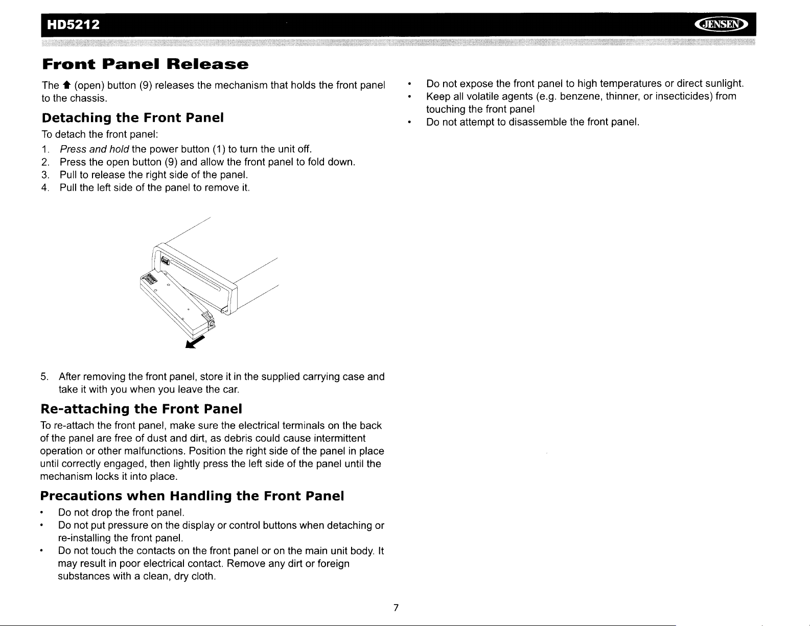
Detaching
To
detach the front panel:
1.
Press and hold the power button (1) to turn the unit off.
2.
Press the open button (9) and allow the front panel to fold down.
3.
Pulltorelease the right side of the panel.
4.
Pull the left sideofthe paneltoremove
Panel
(open) button (9) releases the mechanism that holds the front panel
the
Release
Front
Panel
it.
Do not expose the front paneltohigh temperatures or direct sunlight.
all
Keep
touching the front panel
Do
volatile agents (e.g. benzene, thinner, or insecticides) from
not attempt to disassemble the front panel.
5.
After removing the front panel, store itinthe supplied carrying case and
take it with you when you leave the
Re-attaching
To
re-attach the front panel, make sure the electrical terminals on the back
ofthe panel are free
operation or other malfunctions. Position the right side of the panel
until correctly engaged, then lightly press the left side of the panel until the
mechanism locks it into place.
Precautions
Do
not drop the front panel.
Do
not put pressureonthe display or control buttons when detaching or
re-installing the front panel.
Do
not touch the contactsonthe front panel oronthe main unit body. It
may result
substances with a clean, dry cloth.
the
Front
of
dust and dirt,asdebris could cause intermittent
when
in
poor electrical contact. Remove any dirt or foreign
Handling
car.
Panel
the
Front
Panel
in
place
7
Page 10
~
Operation
HD5212
Power
Press the
(except release) to turn the unit on.
the unit off.
Liquid
The liquid crystal display (LCD) panel (8) displays the frequency, time and
activated functions
when a disc
Press the
HIGH (default) to MIDDLE to LOW.
NOTE:
temperatures
of
the
will
range.
(!)
(power) button (1) or any other buttononthe frontofthe radio
Crystal
of
is
inserted.
(!)
(power) button (1) to change the LCD backlight brightness from
LCD
panels
foranextended
numbersonthe
returntonormal
Press
and
hold the power button to turn
Display
the unit, including a disc indicator, which appears lit
may
take
LCD
when
(LCD)
longertorespond
periodoftime. In
may
decrease
the
temperature
when
addition,
slightly.
increases
subjectedtocold
the
visibility
The
LCD
display
to a
normal
Mode
Press SRC (2) to select a different mode of operation, as indicated on the
display panel. Available modes include
AM1, AM2), SAT RADIO (if connected), COP PLAY (CD), USB
PLAY,
menu only if a CD
NOTE: COP
are
Audio
Press the MUTE button (6) to silence the audio volume. "MUTE" flashes in
the display. Press any button to cancel MUTE.
Volume
To
decrease the volume, rotate the rotary encoder counter-clockwise. When
volume is adjusted, the volume level will be shown on the display panel as a
number ranging from "VOL 00" (lowest) to "VOL 100" (highest).
iPod (if connected) and AUX (auxiliary). COP mode appearsinthe
is
present in the CD player.
PLAY,USB PLAY,SOPLAY,satellite
only
availableifthe
associated
Mute
/
Audio
increase the volume, rotate the rotary encoder (4) clockwise.
Control
HD
RADIOITUNER (F1, F2, F3,
PLAY,
radio
and
iPod
deviceormediaisinserted.
To
SO
modes
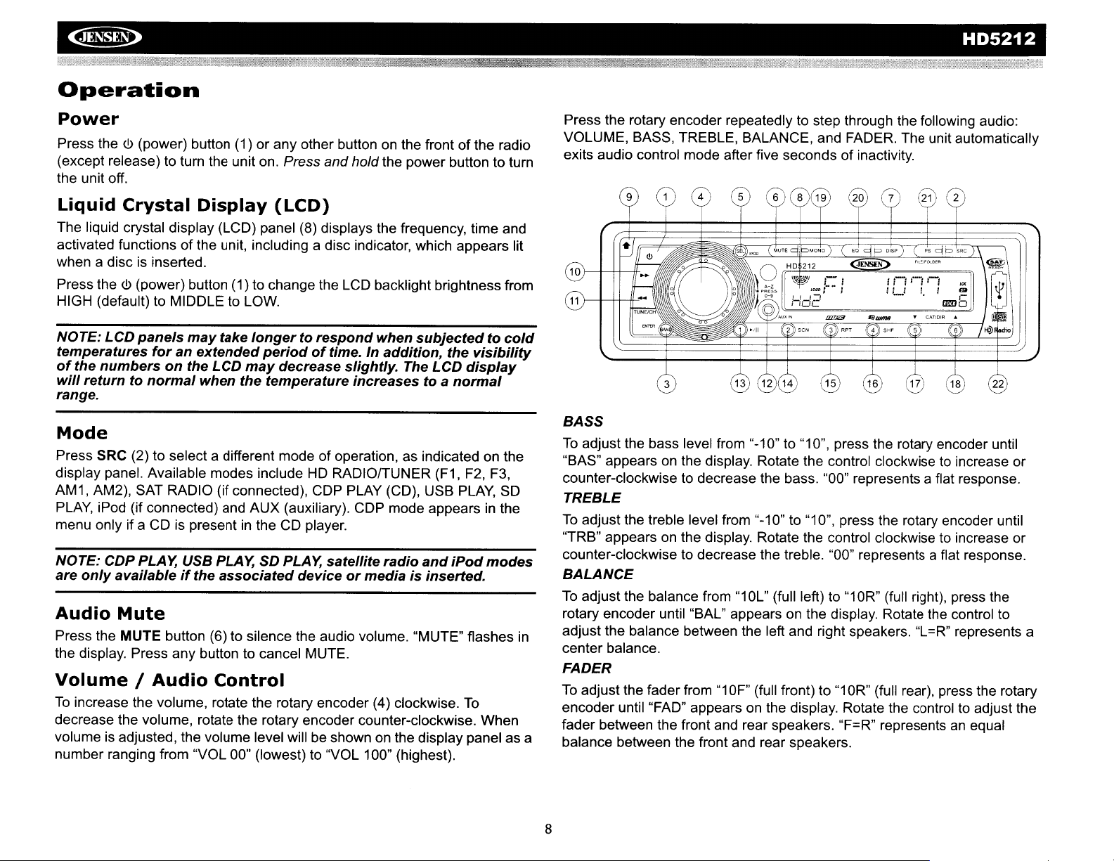
Press the rotary encoder repeatedly to step through the following audio:
VOLUME, BASS, TREBLE, BALANCE, and FADER. The unit automatically
exits audio control mode after five seconds of inactivity.
BASS
To
adjust the bass level from "-10" to "10", press the rotary encoder until
"BAS" appears
counter-clockwise to decrease the bass. "00" represents a flat response.
TREBLE
To
adjust the treble level from "-10" to "10", press the rotary encoder until
"TRB" appears
counter-clockwise to decrease the treble. "00" represents a flat response.
BALANCE
To
adjust the balance from
rotary encoder until
adjust the balance between the left and right speakers. "L=R" represents a
center balance.
FADER
To
adjust the fader from"1OF"
encoder until "FAD" appears
fader between the front and rear speakers. "F=R" represents
balance between the front and rear speakers.
on
the display. Rotate the control clockwise to increase or
on
the display. Rotate the control clockwise to increase or
"10l"
(full left) to"1OR"
"BAl"
appears on the display. Rotate the control to
(full front) to"1OR"
on
the display. Rotate the control to adjust the
(full right), press the
(full rear), press the rotary
an
equal
8
Page 11
HD5212
~
Menu
Press and hold the rotary encoder (4) to access the system menu.
Repeatedly press the rotary encoder button to access menu options
following order:
Operation
in
the
of
BEEP ON/OFF: The beep tone feature allows the selection
be
audible beep tone to
ofthe radio. "BEEP ON"
to select the "BEEP OFF" option.
P--VOL: Turn the rotary encoder to select the default volume the radio
will assume when first turned
PClK
ON/OFF: When "ON", the clock and backlight will remain
when the unitisturned off.
PRI
ClK/SRC:
during playback. Select "SRC" to have the current source appear during
playback. Press the DISP button (7) to temporarily view the alternate
display (clock or source) temporarily.
HOURS 12/24: This option allows selection
clock format. "HOURS 12"
to change to the 24 hour clock format.
S--MODE NORMALlHD SEEK (adjustable only
Select "NORMAL" to allow the radio to search for both digital and
analog stations. Select "HD SEEK" to only search and broadcast digital
stations.
Select
heard each time a buttonispressed on the face
is
the default display. Rotate the rotary encoder
on.
"ClK"
to have the clock appear on the display
ofa12
is
the default setting. Turn the rotary encoder
hour or 24 hour
in
RADIO mode):
an
on
Equalizer
Press the
and treble curves:
EQ
button (20) to choose oneofthe following pre-defined bass
FLAT>
CLASSICS> POP M > ROCK M > DSP
OFF.
Loudness
Press
and
hold the
to music at low volumes, this feature will boost the bass and treble ranges
to compensate for the characteristics
Auxiliary
To
accessanauxiliary device:
1.
Connect the portable audio player to the AUXINjackonthe front panel
(12).
2.
Press the SRC button (2) to select AUX mode.
3.
Press SRC again to cancel AUX mode and go to the next mode.
BAND
Input
button (3) toggle loudness on/off. When listening
of
human hearing.
Setting
Ifnot already showing, press the DISP button (7) to display the clock. With
the clock displayed,
on the display. Press the TUNE/CH
TUNEICH
mode, "AM" or "PM" will appear on the display to indicate
no adjustment
normal operation will resume.
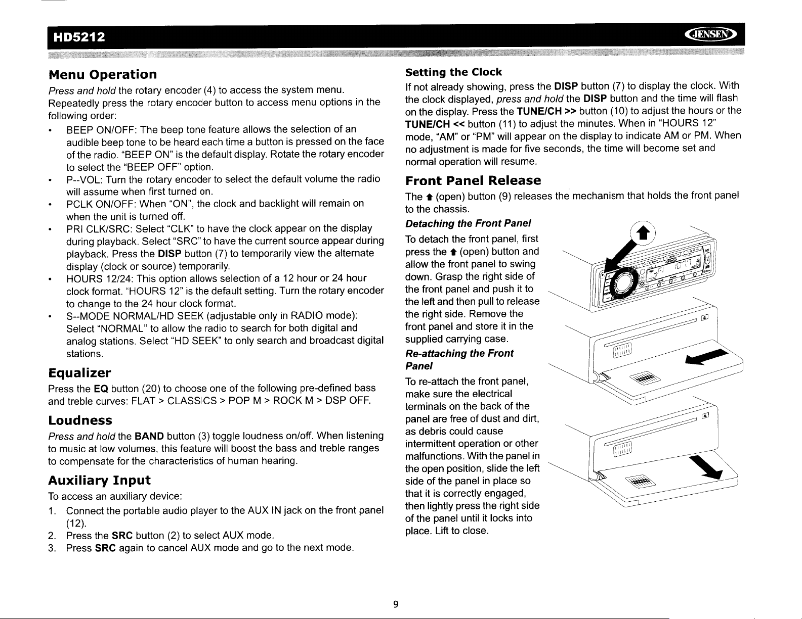
Front
The.
to the chassis.
Detaching the
To
detach the front panel, first
press
allow the front panel to swing
down. Grasp the right side
the front panel and pushitto
the left and then pull to release
the right side. Remove the
front panel and store
supplied carrying case.
Re-attaching the
Panel
To
re-attach the front panel,
make sure the electrical
terminals
panel are free of dust and dirt,
as debris could cause
intermittent operation or other
malfunctions. With the panel
the open position, slide the left
side of the panel
that it is correctly engaged,
then lightly press the right side
of
the panel until it locks into
place. Lift to close.
the
Clock
press
and
hold the DISP button and the time will flash
» button (10) to adjust the hours or the
« button
Panel
(open) button (9) releases the mechanism that holds the front panel
the.
(open) button and
on
the backofthe
(11)
to adjust the minutes. Whenin"HOURS 12"
AM
or PM. When
is
made for five seconds, the time will become set and
Release
Front
Panel
of
itinthe
Front
in
in
place so
9
Page 12

~
HD5212
Reset
The RESET buttonislocated behind the front panel and should
activated for the following reasons:
Use a ball point pen or thin metal object to press the RESET button. This
may
Button
of
initial installation
function buttons do not operate
error symbol on the display
be
necessary should the unit displayanerror code.
the unit when all wiring is completed
be
10
Page 13

HD5212
~
Tuner
Press the SRC button (2) to switch to HD RADIO mode.
About
HD
Radio technology allows CD-quality digital broadcasting of your local
AM
and
channels on the same frequency, whichiscalled multicasting. With
multicasting, you can receive up to three additional multicast channels:
HD2, HD3, HD4. With your HD5212 radio, you will receive HD Radio digital
broadcasts automatically when tuned to a station that offers HD Radio
technology.
Select
Press the BAND button (3) to change between threeFMbands and one AM
band. Each band stores up to six preset stations.
@--+-++-r
Operation
HD
Radio™
FM
radio stations. HD Radio broadcasts can include multiple
a Band
Technology
TUNE/CH « buttons to move the radio frequency number up or down one
step.
Auto Seek Tuning
Press the TUNE/CH
seek the next station.
Mono/Stereo
Press the MONO button (19) to select mono or stereo reception for analog
radio stations.
selecting mono operation. When in stereo mode, the "ST" icon (18) appears
on the display.
HD
Radio Multicast Channels
To
tune toanHD Radio multicast channel, tune to the main signal and then
press the SELECT button (5). If a subchannel is available, the
corresponding multicasting number appearsinthe bottom left corner of the
LCD.
Preset
Six numbered preset buttons store and recall stations for each band.
Store a Station
Select a band (if needed), then select a station. Hold a preset button (13-18)
for three seconds. The preset number will appearinthe display.
Stations
»(10)
You
can sometimes improve receptionofweak stations by
or
TUNE/CH « (11) button to automatically
Tuning
When tuning toanHD Radio channel, "LINKING" will appear on the LCD
while the initial digital information is received. Once linked, "Hd1" appears
the bottom left cornerofthe LCD.
NOTE: Not all FMorAM
You
will receive both analog and digital stations with the HD5212.
Manual Tuning
Press the TUNE/CH » (10) or TUNE/CH « (11) button for more than three
seconds to enter manual tuning mode, then press the TUNE/CH »
stations offer HD Radio (digital) broadcasting.
or
in
PRESS AND HOLD
PRESET NUMBER APPEARS
11
Page 14

~
HD5212
NOTE:
RecallaStation
Select a band (if needed). Press a preset button (13-18) to select the
corresponding stored station.
Preset
Scans stations storedinall
then press the PS button (21). The unit will pause for 5 seconds at each
preset station. Press the PS button again to stop scanning when the desired
station is reached.
Broadcast
During HD Radio broadcasting, available broadcast information will
automatically appear on the LCD. Press the DISP button (7) multiple times
to view broadcast information
The information will scroll across the screen if longer than 8 characters.
HD
Radio
multicast
channels
canbestoredaspreset
Scan
FMorAM bands. Select a band (if needed), and
Information
in
the following order:
Band/Frequency
CH-NAME
TITLE
ARTIST
CATEGORY
Clock (only available when pressing DISP button)
stations.
NOTE: The
Radio
stations
title,
signalisdependent
broadcast
and
categoryofmusic.
amountofinformation
upon
their
call
letters
displayed
whatisbeing
(name), the
when
receivinganHD
broadcast.
artist's
Some
name,
song
12
Page 15

HD5212
~
Satellite
Listeners can
www.xmradio.com.orby
have
their
Radio ID
Code").
channels
Listeners can
www.sirius.com.orby
have
Tuner,
tuningtochannel
Accessing
To
RADIO" or "SIRIUS" appears
unless the unit
Displaying
Before you listen to satellite radio,
your radio's identification number.
CH
where the channel name is usually displayed.
Customers
without
their
SiriusIDready
sold
separately).
switchtosatellite radio mode, press the SRC button (2) until "XM
« button
Radio
subscribe
activation.
subscribe
184.
Satellite
is
connectedanoptional Sirius or
the
(11)
to access channel
to XM® Radioonthe Webbyvisiting
calling
ready
can
receive a
to SiriuS® Radioonthe Webbyvisiting
calling
Customers
CD
,
Identification
Operation
(800) 967-2346.
(see
"Displaying
limited
(888) 539-SIRIUS.
(Sirius ID is
can
Radio
on
Mode
the display. This will notbedisplayed
you
must subscribetothe service using
To
display the radio
ODD.
Customers
the
Identification
numberoffree-to-air
Customers
locatedonthe Satellite Radio
listentomusic
XM
receiver.
(10)
The screen displays the radio
Code
ID,
press the TUNEI
should
(ID)
should
samples
by
ID
SelectingaStation
Press the TUNE/CH » or TUNE/CH « button (10 and
another station.
more than one second to fast forward or fast reverse through the stations.
Preset
Press the BAND button (3)tochange between three user preset channel
groups. Each channel group stores
and recall a total of
Store
a Station
1.
Select a channel group, then select a station.
2.
Hold a preset button (13 - 18) for three seconds. The preset number
appears
Recall
1.
2.
a Station
Select a channel group.
Press a preset button (13 - 18) to select the corresponding stored
station.
Tuner
Press the DISP button (7) to change the tuner modetothe following options
in
the order listed.
Channel Name
Genre (News, Sports, Hits, Kids, etc.)
Artist name
Song Name
Ifthe selected channel name, artist, or title exceeds eleven characters, the
display information will scroll twice upon selection.
Direct
To
1.
2.
3.
4.
5.
Tuning Mode
enter a station directly, perform the following steps.
Press the SELECT button (5)toenter direct tuning mode.
Turn the rotary encodertodisplay "XM
Turn the rotary encoder againtoselect the first digit of the desired
channel
Press the BAND/ENTER button (3)toenter the first number and move
to the second position.
Turn the rotary encoder again to select the second digit of the desired
channel
Press and holdthe TUNE/CH » or TUNE/CH « button for
Stations
uptosix preset stations.
18
preset stations.
in
the display.
Modes
CH
(0,1,or 2).
(0-9).
11)tochange to
You
" or "SR
CH
can store
".
13
Page 16

~
6.
Press the BAND/ENTER buttontoenter the second number and move
to the third position.
the
the
Mode
TUNEICH»
first
and
(0
third
- 9).
NOTE: Use
between
7.
Turn the rotary encoder againtoselect the third digit ofthe channel you
want to tune to
8.
Press the BAND/ENTER button to enter the third number and access
the channel.
Category
To
select stationsina specific category, perform the following steps.
1.
Press the SELECT button (5) twicetoselect "CATEGORY" mode.
2.
Press the CAT/DIR1\and V buttons (17,18), labeled "5" and "6", to
select the desired category.
3.
Press the BAND/ENTER button (3) to confirm.
4.
Once a categoryisselected, use the TUNE/CH » or TUNE/CH «
buttons to select stationsinthe current category.
To
exit category mode. press SELECT.
or
TUNElCH«
positions.
button
(10
and
11) to
HD5212
move
14
Page 17

HD5212
~
CD
cop mode can only be accessed when a disc
alreadyinplace, press the SRC button (2)toaccess
playback automatically.
Insert
Press the open button (9)
and allow the front panel to
fold down to display the
disc slot. With the label
surface facing up, fully
insert a compact disc into
the slot until the
mechanism engages and
pulls the disc
inserting a disc, lift the front
panel up to return it to the
closed position and begin
playing the disc.
Eject
To
the open button (9) and
allow the front panel to fold down to display the disc slot (24).
Press the eject button (25) located to the right of the disc slot to eject the
disc. If the disc
be
Player
Operation
CD
in.
After
CD
eject a disc, first press
is
not removed from the unit within 15 seconds, the disc will
reloaded to prevent accidental damage.
is
inserted. If a disc
COP
mode and begin
is
will appearonthe display. Press
« (11) button for more than one second to fast forward or fast reverse
CH
through the disc. CD play starts when the button
Intro
During disc
on the disc. When the desired track is reached, press 2/SCN again to end
the scan and play the selected track.
Repeat
Press 3/RPT (15) during disc play to continuously repeat the track. Press 3/
RPT again to stop repeating.
Random
Press 4/SHF (16) during disc play to play all tracks on a CDinrandom,
shuffled order. Press 4/SHF again to stop random play.
Display
Press the DISP button (7) to display any text encoded on the CD (song title,
artist, etc.).
Scan
play,
(RPT)
(SHF)
103
(SCN)
press 2/SCN (14) to play the first 10 secondsofeach track
Tag
Information
and
hold the TUNE/CH » (10) or TUNE/
is
released.
60
19
NOTE: The
discs
either
disc
may
this
product.
unitisdesigned
only. Do
withorwithout
occur.
not
Such
for
playofstandard
attempttouse
an adaptor,asdamage to the
damage
3"
(8 cm.)
will
notbecoveredbythe
Pause
Press the
button again to resume disc play.
Track
Press the TUNE/CH » (10) or TUNE/CH
second to advance to the next track
1/>/11
button (13) to suspend disc play. Press the play/pause
Select
on
5"
(12 cm.)
CD
singlesinthis
player
«(11)
the CD. The selected track number
button for less than one
compact
unit,
and/or
warranty
the
on
CD
Player
If a problem should develop while operating the CD player,anerror code
1,
(Error
number of problems with the unit, including a mechanical error or
the microprocessor controlofthe player. Ifanerror code should appear, try
15
Error2,etc.) may appearonthe display panel. This can indicate a
Error
Codes
an
error
in
Page 18

~
ejecting and reloading the disc into the player. While the disc is outofthe
is
unit, make sure it
does not solve the problem, pressing the reset button may help, but will
erase the time and preset memory. If the suggested measures do not solve
the problem, contact
customer service at 1-800-323-4815 for further assistance.
clean and undamaged, and then load it correctly. Ifthis
an
authorized warranty station near you or contact
HD5212
Electronic
This unit is equipped with electronic shock protection as follows:
20 seconds for CODA (COA)
120 seconds for MP3 recorded at 44.1 kHz, 128kbps
200 seconds for WMA recorded at 44.1 kHz, 128kbps
Shock
Protection
(ESP)
16
Page 19

HD5212
~
MP3/WMA
MP3 and WMA (Windows Media Audio) music files are digital audio files
that are compressed to allow more files
MP3/WMA directly from files contained
device using the buttons
described below. Many types
files into MP3IWMA formats. Jensen recommends
Creator. Depending
RWs maybeincompatible with this unit. This unit supports playback
MP3/WMA and CODA (CDA), Mixed-Mode CDs and CD-Extra (including
multi-session discs).
will
not
play.
Notes
This unit can play MP3 (MPEG1,2,2.5 Audio Layer
recording media and accepted formats are limited. When writing
WMA, pay attention to the following restrictions.
on
MP3/WMA
Operation
on
a single CD. This unit can play
on
a CD-R/RW,
on
the receiver (or optional remote control) as
of
software are available for converting audio
on
the media type and recording method, some CD-RI
Discsonwhich
the
session
Play
SO
card or USB
Nero or Roxio Easy
has
not
been
closed
3).
However, the MP3
MP31
CD
of
Acceptable Media
The MP3IWMA recording media acceptable to this unit are CD-ROM, CD-R
SO
and CD-RW,
format rather than quick format to prevent malfunction.
cards and USB devices. When using CD-RW, use full
Acceptable Medium Formats
The following formats are available for the media usedinthis unit. The
maximum number of characters used for file name including the delimiter
.....
) and three-character extension are indicatedinparentheses.
(
ISO 9660 Level 1
ISO 9660 Level 2
Joliet
(31
characters)
Romeo
Up
to 200 characters canbedisplayedinthe long file name format. For a
list of available characters, see the instruction manual of the writing
software and the section "Entering File and Folder Names" below. The
media reproducible
Maximum number of nested folders: 8
Maximum number
Maximum number
Maximum number of files per media device: 2000
MP3IWMA written
successfully and their file names or folder names will not
properly.
(31
(11
characters)
(31
characters)
characters)
on
this unit has the following limitations:
of
files per disc: 999
of
folders per disc: 255
in
formats other than those listed above will not play
be
displayed
MP3IWMA
Use the following settings when compressing audio datainMP3 data with
the MP3 encoder.
Transfer bit rate:
Sampling frequency:
44.1, 48kHz (MP3)
When using a
capacity, disable additional writing.
maximum capacity at once, select the "disc at once" option.
Entering
This unit supports
and 1.1. For the character codes, refer
to the table to the right.
Entering
Names using the code list characters
are the only file names and folder
names that
displayed. Using any other character
will cause the file and folder names to
be
displayed incorrectly. The unit
recognizes and plays only files with the
MP3IWMA extension.
NOTE: A file name entered
not
play
Writing
When a medium containing MP3IWMA data is loaded, the unit checks all
data. If the medium contains many folders or non-MP3/WMA files,
WMA play willbedelayed, it may take time for the unit to move to the next
file, and searches may not
Loading such a medium may produce loud noise and cause damage to the
speakers.
with
file
Encoder
CD
ID3
Tag
File
and
canbeentered and
and
CD
Writer Settings
32
- 320 kbps
32,
44.1, 48kHz (WMA) and 16, 22.05, 24,
writer to record MP3/WMA up to the maximum disc
103
tag versions 1.0 0 1
Folder
Names
with
correctly.
Files
into
a Medium
be
performed smoothly or it may not play at all.
Do
not
attempttoplaya
the MP3IWMA extension
To
record an empty disc up to the
characters
medium
oramedium
notonthe
containing
containing
code
a non-MP3IWMA
list
non
32,
may
MP31
MP31
WMA files.
Bit
Rates
The unit supports bit rates from32- 320 kbps.
17
Page 20

~
File
Playing
When selected for play, files and folders (Folder Search, File Search or
Folder Select) are accessed
As a result, the order
match the order
the order
medium such as a CO-R with their file names beginning with play sequence
numbers such as "01" to "99".
For example, a medium with the following
Folder Search, File Search or Folder Select as shown below.
Order
in
the order they were written by the
in
which they are expected to be played may not
in
which they are actually played.
in
which MP3/WMA are to be played by writing them onto a
You
may be able to set
folder/file hierarchy is subject to
CO
writer.
HD5212
Installing
Gently lift the rubber USB slot cover (22) from the top and pull it down.
Insert your USB thumb drive into the USB slot
unit will automatically search for MP3 and
begin playback.
pressing the SRC button (2). "USb"
the LCD.
NOTE:
memory
Not
all
sticks
a USB
You
USB
approvedbyMicrosoft
Device
on
the frontofthe radio. The .
WMA
filesonthe device and
can access USB PLAY mode from any other mode by
is
displayedinthe bottom left corner
devices
are
supportedbythis
are
unit.
supported.
Standard
of
USB
.-----Q]
1-
J>
,
I--J>
i------ 1>,
:~'
I
~'--_'cp-
L____
6
-QJ
l
Levell
Level
Loading
Press the open button (9) to lower the front panel, then Insert an MP3/WMA
disc. After the disc is loaded, the track number and elapsed time will appear,
then the display will scroll through any
playing. If the disk contains
pressing the DISP button (7). If no
will display the elapsed time. When
will alternate between track name and formaUtrack number.
an
MP3/WMA
...............
-W
L_J>'O
level
2 Levf!1 4
103
tag information, you can scroll through it by
~
-.t."
oJ'
',.
_
1>",
1>$
3
CJ
1>
:§)
Folder
File
Root
Disc
103
Tag
information while the file is
103
tag information is available, the unit
103
informationisavailable, the display
WARNING:
Press
Do
not
remove
the
device
SRC (2)tochangetoanother
when USB
mode
before
PLAY
removing
7
@2
modeisactive.
the device.
I
Loading
Insert the
panel. Replace the front panel when finished.
NOTE: You
See
"Detaching
The unit will read the files on the card automatically. "Sd" appears in the
bottom left corner
To
remove the card, first press the SRC button (2) to switch to another
mode and stop
straight out. Most cards have a thin recess that helps with removal.
an
SO
Card
SO
card, label side up, into theSOslot located behind the front
must
remove
the
of
the display when an
SO
playback. Pressinon the card to eject it, and then pull it
the
Front
Panel"onpage
front
paneltoaccess
7.
SO
card is being read.
the SD
card
slot.
18
Page 21

HD5212
~
Pause
Press the
button again to resume play.
Track
Press the TUNE/CH » (10) or TUNE/CH « (11) button for less than one
second to advance to the next track on the disc, or press and hold to fast
forward or fast reverse through the disc. Disc play starts when the button is
released.
Navigating
Press the CAT/DIR1\and V buttons
folder/directory.
Intro
During disc
on
the disc. When the desired track is reached, press SCN again to end the
scan and play the selected track.
Repeat
Press the RPT button (15) to repeatedly play the current file. Press RPT
again to resume normal playback.
Random
Press the SHF button (16) to randomly play all filesonthe disc. Press SHF
again to resume normal playback.
MP3/WMA
The unit offers four methodsofsearching for files or foldersona disc.
Direct
Press thePSbutton (21) to enter Direct Track Search mode. The LCD will
display "MP31"followed by a blinking asterisk. Refer to the Number
columninTable 1 to enter a track number for playback:
1/>/11
Select
Scan
(RPT)
File
Number
button (13) to suspend disc play. Press the play/pause
Folders
(17,18)
to select the next or previous
(SeN)
play,
press SCN (14) to play the first 10 seconds of each track
(SHF)
File
or
Folder
Search
Search
Table 1: Search
Key Number
1
>/11
2 SCN
3 RPT
4 SHF
5
6
SRC
TUNE/CH «
TUNE/CH»
DISP
You
can also use the rotary encoder (4) to enter search characters. Press
the rotary encoder to confirm each entry.
If
you enter a three-digit track number, the unit will search the track
immediately. If you enter one or two digits, press the BAND/ENTER button
(3) to begin the search, or wait a few seconds for the search to begin
automatically.
Characters
1
2
3
4
5
6
7
8
9
0
Characters
A,B,C
D,E,
F
G,H,I
J,
K,
L
M,N,O
P,O, R
S,T,U
V,W,X
Y,Z,blank
-,
+
-
Directory/File Search
1.
Press the PS button (21) twice to enter DirectoryorFile Name Search
mode. The LCD will display a blinking asterisk.
2.
Use the keys specifiedinTable 1 or turn the rotary encoder (4) to enter
a search string.
3.
Press the rotary encoder button to confirm each character.
4.
Press the BAND/ENTER button (3) to begin the search.
Ifthe search resultsina directory name,('') will appear on the display.
1.
In
this case, use the TUNE/CH » (10) or TUNE/CH « (11) buttons to
select a song/folderinthe directory.
2.
Press the BAND/ENTER button (3) to confirm and begin playback.
3.
Repeat ifthe search resultsinanother directory.
Root
Directory
1.
Press the PS button (21) three times to enter Root Directory Search
mode. The LCD will display a seriesofquestion marks (??????) followed by the first folder or file nameinthe root directory.
Search
19
Page 22

~
2.
Turn the rotary encoder (4)tobrowse all available folder or files in the
root directory.
3.
Press the rotary encoder button to select a folder or file.
')
If a folder is selected, two apostrophes ('
is
indicating that the selection
select a file for playback.
is
If a file
Current
1.
2.
3.
Directory
Press the PS button (21) four timestoenter Current Directory Search
mode. The LCD will display the current directory name, followed by the
file currently playing.
Turn the rotary encoder (4)tobrowse all available folders or filesinthe
current directory.
Press the rotary encoder button to select a folder or file.
If a folder is selected, two apostrophes ('
indicating that the selection
select a file for playback.
If a file is selected, playback begins automatically.
Select ('
directory or file.
selected, playback begins automatically.
Search
')
to returntothe previous file level and select a different
a folder. Repeat steps 2 and 3 to
is
a folder. Repeat steps 2 and 3 to
appearonthe LCD,
')
appearonthe LCD,
HD5212
Display
Press the DISP button (7) to display the clock or available ID3 information,
as follows: song title, directory name, artist name, etc.
Information
20
Page 23

HD5212
~
iPod
Accessing iPod
This unitisequipped withaniPod ready function that will allow you to
control your iPod (if compatible) using the front panel control buttons. The
following iPod versions are supported:
iPod
iPod Mini
iPod Photo
iPod Nano
iPod
The unit will automatically switch to iPod mode when
into the iPod cable.
press the SRC button (2) on the front panel or remote control until "IPO"
appears
NOTE: The HD5212
not
a video file was the
into
10
l--I-f+--II-.
Operation
3G
5G
on
the display.
the radio.
Mode
(Firmware version 2.2 only)
(Video)
To
return to the iPod menu from any other source menu,
will
not
Only
last
music
select
file
files are supported.
video files regardlessofwhether
playing
~19
6
when the
an
iPodisplugged
iPod
was
@2
7
plugged
@-
or
NOTE: The
as
long
Display
iPod song information, when available, appearsonthe LCD screen
automatically during playback. Press the DISP button (7) to manually
display iPod playback information
Track/Elapsed Time
Song TITLE
ARTIST
CATEGORY (Album Name)
Clock
iPod
will
as the vehicle
Information
continuously
ignitionisturned
recharge when
in
the following order:
on.
connected
to unit,
Play/Pause
Press the
display when paused.
Track
Select
Press the TUNE/CH » (10) or TUNE/CH « (11) for less than 1 second to
advance to the next song
playing for at least one second, press the TUNE/CH « (11) to replay the
song from the beginning. When a song has been playing for more than one
second, you must press TUNE/CH
Fast
Press and holdthe TUNE/CH » (10) or TUNE/CH « (11) for more than 1
second to fast forward or fast reverse. Playback begins when the button is
released.
1/>/11
Selection
a Track
Forward
button (13) to suspend or resume play. "PAU" flashesonthe
in
the current category. When a song has been
«twice
/ Fast Reverse
to move to the previous file.
Turning
The iPod power turns on automatically when the iPodisconnected to 30pin iPod cable, as long
the iPod off
When the ignition
mode after 2 minutes.
the
iPod
by
disconnectingitfrom the cable or by turning the ignition off.
is
On/Off
as
the automobile ignitionisturned on.
turned off, the iPod will pause and then enter sleep
You
can turn
Repeat
Press the RPT button (15) during disc play to continuously repeat the
selected song. Press RPT again to stop the repeat function.
Press and hold the RPT button (15) for more than 3 seconds to
continuously repeat the entire album/folder. Press and hold RPT again to
stop the repeat function.
(RPT)
21
Page 24

~
HD5212
Shuffle
Press the SHF button (16) to randomly play the files in all folders Press SHF
again to stop the shuffle function and resume normal playback.
Press and hold the SHF button to randomly play the files
album (folder). "SHF ALBM" appears
again to stop the shuffle function.
Category
1.
During iPod playback mode, press the SELECT button (5) to enter iPod
Category Search Mode.
2.
Turn the rotary encoder (4) to access categoriesinthe following order:
3.
After selecting the desired category, press the BAND/ENTER button (3)
within 5 seconds to confirm.
4.
Turn the rotary encoder (4) to browse songs or folders in the current
category.
5.
Press the BANDIENTER button (3) within 5 seconds to select a
category/song.
6.
Repeat steps 4 and 5 until the desired songisplayed.
(SHF)
Search
Playlist
Artist
Album
Genre
Song
Composer
Mode
on
the display. Press
in
the current
and
hold SHF
22
Page 25

HD5212
Re
....
ote
The remote control will allow you to control the basic functionsofthe
HD5212. The remote control sensor is at the top left below the SELECT
button (5).
Control
~
Table 2: Remote
Player
Key
1
2
3
4 Volume
5 Volume Down
6
7
8
9
10
11
12
13
14
15
16 Preset Scan
17 Access Multicast
Tuner
Power On/Off Power On/Off PowerOn/Off
LCD Dimmer
Select Source Select Source
Audio Menu Audio Menu Audio Menu Audio Menu
Up
Channel Up Track Up File Up File Up Channel Up
Channel Down Track Down
Change Band/ Confirm Entry Confirm Entry
Confirm Entry
Display/Set Clock Display/Set Clock Display/Set Clock
Broadcast Information mation
Preset Station 1 Play/Pause
Preset Station 2 Intro Scan Intro Scan Intro Scan
Preset Station 3 Repeat Track Repeat File/ Repeat File/ Preset Station 3
Preset Station 4 Shuffle Tracks Shuffle All/Shuffle Shuffle All/Shuffle Preset Station 4
Preset Station 5 Folder Down Folder Down Preset Station 5
Preset Station 6 Folder Up Folder Up
(HD Radio only)
CD
LCD Dimmer
Volume Up
Volume Down
Control
LCD Dimmer LCD Dimmer LCD Dimmer
Select Source
Volume Up Volume Up Volume Up
Character Entry Character Entry
Volume Down
File Down
103
Information
Play/Pause
Repeat Folder
Folder
File/Folder Search Preset Scan
MP3
Functions
iPod
Power On/Off
Select Source Select Source
Volume Down Volume Down
File Down Channel Down
Confirm Entry Change Band/
Display/Set Clock
103
Information Broadcast Infor-
Play/Pause Preset Station 1
Repeat Folder
Folder
Search Files
Power On/Off
Audio Menu
Confirm Entry
Display/Set Clock
Preset Station 2
Category Down
Preset Station 6
Category Up
Direct Tuning
Satellite
DIM
7
8
--_n~B
~
III
14r---++-------"
I+l
\..
yot----/---l-+---{
(£)
seN
RPT
8
(iLGJ
e-I
----+1--{
GtENSE[)
15
23
Page 26

~
HD5212
Care
CD
Player
The following guidelines will help you extend the lifeofyour CD player:
1.
When cleaning the vehicle interior, do not get
the unit.
2. The CD player will not operate properly
damp
interior reaches a normal temperatureorany condensation on the disc
player lens has evaporated before using the player.
3.
Never
Attempting to insert CDsofother sizes (even with an adaptor) will
cause damage
and
conditions. In caseofsuch conditions,
insert anything other than round5"CDs into the player.
Maintenance
not
coveredbythe warranty.
waterorcleaning fluids on
in
extreme hot/coldorunder
wait
until the vehicle
4. Always remove the CD when the player is not is use.
5.
The unit is designed with a vibration dampening
minimize interruptionofdisc play due to normal vibration in a moving
vehicle. However, occasional sound skips may
very rough roads. This will not scratchordamage the disc, and normal
play will resume when the rough conditions cease.
Compact
CD-R
and
Depending on media type and methodof"recording/burning",
RWs
may
session must be closed. Please refer to your software's recommended
procedures
familiarize yourself with the correct "recording/burning" procedures.
recommend using the latest versionsofROXIO™orNERO
software.
In addition, this unit will only recognize the CODA (Compact Disc
Digital Audio), .MP3 and .WMA formats
RW. This unit does not support
CD Care
Dirt, dust, scratches and warpage can cause skips in the playback and
deteriorationofsound quality. Please follow these guidelines to take care
your
compact discs.
1. Carefully wipe fingerprints, dust and dirt from the disc's playing surface
with a soft cloth. Wipeina straight motion from the inside to the outside
of
the disc.
Discs
CD-RWCapability
be incompatible with this unit. After "recording/burning", the
for
closing a disc/session. Review your recording software to
"recorded / burned" onto a
and
.WAV,
Handling
.OGG or other formats.
CD
mechanism to
occur
when driving on
some
CD-R/
We
™ burning
CD-R/
of
2. Never use chemicals such as record sprays or household cleaners to
clean CDs, as they can irreparably damage the disc's surface.
3. Discs should be kept in their storage cases when not
in
use.
4. Do not expose discs to direct sunlight, high temperatures or high
humidity for long periods.
5. Do not stick paper, tape
damage may occur.
or
CD labels on disc surfaces, as internal
24
Page 27

HD5212
Troubleshooting
Problem Cause Corrective Action
Does not operate No power to yellow wire; Check connection with test light;
(display does not no power to red wire check vehicle fuse with test light
light)
No power to unit Fuse blown
No speakers oper- Speaker harness not con-
ate (display lights nected speaker wires
normally)
Not all speakers Incorrect splices
operate
Blows fuses Power wire shorting to Make sure wire is not pinched
CD skips too much
ERROR 1
No File
Disc error Disc dirty, scratched, Replace with clean, properly
Fuse blown
Front panel not installed Reinstall front panel
properly
or
nections tions
Speaker wires shorting to Check splices, insulate all bare
chassis ground or to each wires
other
ground
Speaker wires shorting to Make sure wire is not pinched
ground
Incorrect fuse/fuse too
small
Receiver mount is not
solid or backstrap is not
secure
Installation angle more . Adjust angle to less than 30%
than 30%
Mechanism error
No supported files found Insert different disc card with
on disc/card appropriate file type
upside down installed disc
con- Check all splices and connec-
Replace fuse
Check/replace fuse
Connect speaker harness; check
of
Install fuse
Check mounting and backstrap,
tighten if needed
Press reset button
correct rating
~
25
Page 28

~
Specifications
CEA Power Ratings
Power Output 13 Watts RMS x 4 channels into
Signal to Noise Ratio 70dBA below reference (Reference: 1
Frequency Response 20 Hz - 20 kHz, -3dB. (Aux Input used as reference input)
Reference Supply Voltage 14.4VDC
CD Player
Compatible Disc Media CD-RlRW
Compatible Media Formats CD-DA, MP3,
Signal to Noise Ratio @ 1
Frequency Response 20Hz to 20 kHz, -3dB
Channel Separation > 60dB
D/A Converter 1bitlchannel
kHz.
. . . . . . . . . . . . . . . . . . . . . . . . . . . . . . . . . . . . . . ...>90dB
FM Tuner
Tuning Range 87.5MHz - 107.9MHz
Mono Sensitivity (-30dB). . . . . . . . . . . . . . . • . . . . . . . . . . . . . . . . . . . . . . . . . . . . . .
Quieting Sensitivity (-50dB) 15dBf
Signal to Noise Ratio
Stereo Separation
Frequency Response 30Hz - 12kHz, -3dB
AM
Tuner
Tuning Range 530 kHz - 1710 kHz
Sensitivity (-20dB) 15uV
Signal to Noise Ratio
Frequency Response 50Hz - 2kHz, -3dB
@ 1 kHz 58dB
@ 1 kHz >30dB
@ 1 kHz 50dB
AuxiliaryInput
Input Sensitivity
Frequency Response _. _ _ 20Hz to 20kHz, -3dB
Input Impedance _ 10k ohms
AOOmV
4-0hms
RMS for 1 watt RMS into 4-ohms
@
~
1% THD+N
Watt,4-0hms)
WMA
@ 1 kHz
..11dBf
HD5212
General
Power Supply
Power Antenna (Blue) 500mA max, current limited protection
Operating Temperature -20C - 65C
Fuse 15-amp, ATO type
DIN chassis dimensions 7" X 7" X 2" (178mm x 178mm x 50mm)
Specifications subject to change without notice.
11
to 16VDC, negative ground
26
Page 29

Limited
Warranty
CDorMultimedia
DO NOT RETURN THIS PRODUCT TO THE STORE
Radios/Headunits
Audiovox
quality
Warranty. Please readitthoroughly
323-4815
Electronics
and
customer
with
any
questions.
Corporation
service, and are pleasedtooffer
("the
Company")iscommitted
and
contact
the
Companyat1-800-
you
to
this
Whoiscovered?
The Company extends this warrantytothe
purchased throughanauthorized Audiovox retailerinthe
This
Canada.
requiredinthe
warrantyisnot
formofan
transferable or assignable. Proof of purchase
original sales
original retail purchaser of products
U.S.A.,
receipt.
Puerto
Rico
Whatiscovered?
The Company warrants that should this product or
use,beproven
date of original purchase,
reconditioned
repair labor.
Whatisnot
This Warranty does not cover the following:
• Damage incurred during shipping or transporting the product to the
Company or a service center
• Elimination of car static or motor noise
• Defects
• Correction of antenna problems
• Costs incurred for installation, removal or reinstallation
• Consequential damage to compact discs, USB devices, digital media
cards, accessories or vehicle electrical systems
• Damage caused by improper installation, mishandling, misuse, neglect,
accident, blown fuse, battery leakage, theft or improper storage
• Products whose factory serial number/bar code label(s) or markings
have been removed or defaced
• Damage resulting from moisture, humidity, excessive temperature,
extreme environmental conditions or external natural causes
Please
and Operation Manual
useofyour
review
defectiveinmaterial
such
product
(at
the
or workmanship within12months from the
defect(s)
Company's
willberepairedorreplaced
option)
covered?
in
cosmetic, decorative or non-operative structural parts
the "Care and
product.
for
additional
Maintenance"
information
any
part thereof, under normal
withanew
without charge for parts and
of
the product
sectionofyour
regarding
Installation
the
proper
or
Limitations
THE EXTENT OF THE COMPANY'S LIABILITY UNDER THIS WARRANTY
IS
LIMITEDTOTHE
IN
NO
EVENT,
PURCHASE
This
Warrantyisin
is
or
WARRANTIES,
MERCHANTABILITY, SHALL
WRITTEN WARRANTY. ANY ACTION FOR BREACH OF ANY WARRANTY
HEREUNDER INCLUDING ANY IMPLIED WARRANTY
MERCHANTABILITY MUST
MONTHS FROM DATE
COMPANY
DAMAGES
OR
IMPLIED, WHATSOEVER. No person or representativeisauthorized to
assume for
with
the sale ofthis product.
Some states
exclusion or limitation of incidental or consequential damage
limitations or exclusions may
legal
rights
Obtaining
• To obtain repair or replacement within the termsofthis Warranty,
• You must prepay the initial shipping charges to the Company.
• Please package the product securely to avoid shipping damage.
• Provide a detailed description
PRICE
BE
FOR
the
do
and
Warranty
call 1-800-323-4815 for the location
your area.
The Company will pay the return shipping charges for all
warranteed products returned to an address within the U.S.A.,
Puerto Rico
We recommend using a carrier that provides tracking service to
prevent lost packages. Lost
covered by this warranty.
require service.
REPAIRORREPLACEMENT
SHALL
PAIDBYPURCHASER FOR THE PRODUCT.
lieuofall
INCLUDING
LIABLE
BREACH
Company any liability other than expressed hereininconnection
not
allow limitationsonhow
you may also have other rights which vary from state to state.
THE
COMPANY'S LIABILITY
other express warranties or liabilities. ANY IMPLIED
ANY
BE
LIMITED TO THE DURATION
BE
BROUGHT WITHIN A PERIOD
OF
ORIGINAL PURCHASE.INNO
FOR
ANY
CONSEQUENTIAL
OF
THISORANY OTHER WARRANTY,
longanimplied warranty
not
applytoyou. This Warranty gives
PROVIDED
IMPLIED
ABOVE
EXCEED
WARRANTY
CASE
SHALL
OR
INCIDENTAL
EXPRESS
lastsorthe
so
the
you
AND,
THE
OF
OF
above
specific
THIS
THE
Service
of
a warranty station serving
or
Canada.
or
damaged packages are not
of
the problem(s) for which you
OF
OF
24
Page 30

If
It', too
LOUD
-
~'retoo
OLD!
Audiovox Electronics Corporation
Hauppauge, NY 11788
Technical Assistance: 1-800-323-4815
www.jensen.com
© 2007 Audiovox
Ver.
101207
Printed
in
China
1111111111111111111111
30602490
8800-0C50
16-03
Page 31

HD5212
Receiver
Quick
Start
Guide
r;:==lillJ~~~"'~
[[J[S]EJIlJ~O
IID=======~=====~========51:;::;;;g
o
t'============::::;:=:::===============
SIRIUS
Antenna
XM
XM
L XM R
TERK XMDJEN100 cables
Direct
TERK XMD1000
SiriusConnect SC·C1
Tuner
tuner
sold
and
sold
Connector
separately.
antenna
separately.
sold
separately.
Power
connect
~
.........................................
JLink iPod
Cable (Included)
=
Satellite
Radio
Tuner
~
= =
=
*
Amplifier
Connect line out for optional
external amplifiers. The RED
connector
Antenna
to power antenna
or amplifier. If not used,
tape bare end of wire.
is
the WHITE connector
White/Black (-)
(BLUE)
Wiring
(GRAY)
for the right and
for the left.
is
~===l
Ground
(BLACK)
Connect to ground
terminal or clean,
unpainted part
'------c@*
Memory/Battery
Connect to battery or 12 volt
power source that
The radio will not work
wire
is
not connected.
Accessory/Ignition
Connect to existing radio
w;rn
"'
"';0
'""
Gray/Black
(-)
IMPORTANT:
connections
unit.
Follow
instructions
the
installation
experienced
of
chassis.
(YELLOW)
is
always live.
if
this
~
U
(RED)
-p
Incorrect
can damage the
the
wiring
carefully,orhave
handledbyan
technician.
wiring
D
@
iPod Gen5
D
0000
@
iPod
D
®
iPod
Mini iPod Nano
~
LF/AVG@~
White (+)
Green/Black
(-)
'~AAG~==Gree==n(+~)
~@O
Gray (+)
Violet/Black (.)
~Vio=let(+=)
~
RF/AVD
Need
technical
customer
at
R~m
help?
For
assistance,
call
the
Jensen
support
1-800·323·4815.
line
8800-0CS016-04
Page 32

v;£'·torJ'Techllolov;es
~
0
1.
Visit www.jensen.com.
2. Click
on
'i.,,:~
INSTALLATION
excellence
Three easy steps!
the
Victory
Technology
'I~~,~$i~1~*~;~~~=
__
~~~t~~~~~~
3.
4.
Installation Excellence Logo as
shown above.
Enter
(example:
Follow the
your
product
serial
number
xxxx_xxxxxxx_xx).
-
.-
_.._
..
-,-
- -' -
o~-~,~r,y\ensteps
Page 33

PRODUCT REGISTRATION
Thank
and
haveaquestion,
www.audiovox.com
II
II
you
reliability
PRODUCT
In
case of
your registration will serve
PURCHASE
for
purchasingaJENSEN
of
all
our
our
PROTECTION:
an
REGISTRATION:
product.
electronic
customer
insurance loss such as fire, flood or theft,
products
service
as
staff
proof
We
but
stands
pride
if
you
of
ourselves
ever
ready
purchase.
need
to
help.Contact
on
the
service
quality
or
us
at
Registering On-line will allow us
unlikely event a safety notification is required under the
Federal Consumer Safety Act. .
to
contact you
in
the
098-27063
Page 34

Register
Online
at:
WWW.AUDIOVOX.COM
Click
and
Fill
on
Out
Product
the
Brief
Registration
Questionnaire
 Loading...