

Jenn-Air WALL-MOUNT CANOPY RANGE HOOD Installation Instructions And Use & Care Manual

JENN-AIR® 30" AND 36" (76.2 CM AND 91.4 CM)
WALL-MOUNT CANOPY RANGE HOOD/
HOTTE DE CUISINIÈRE POUR MONTAGE MURAL
30" ET 36" (76,2 CM ET 91,4 CM)
Installation Instructions and Use & Care Guide
For questions about features, operation/performance, parts, accessories, or service in the U.S.A., call:
1-800-JENNAIR (1-800-536-6247) or visit our website at www.jennair.com.
In Canada, call: 1-800-807-6777, or visit our website at www.jennair.ca.
Instructions d’installation et Guide d’utilisation et d’entretien
Au Canada, pour assistance, installation ou service, composez le 1-800-807-6777 ou visitez notre site web à www.jennair.ca.
Table of Contents/Table des matières2
IMPORTANT: READ AND SAVE THESE INSTRUCTIONS.
FOR RESIDENTIAL USE ONLY.
IMPORTANT : LIRE ET CONSERVER CES INSTRUCTIONS.
POUR UTILISATION RÉSIDENTIELLE UNIQUEMENT.
W10134195
TABLE OF CONTENTS
RANGE HOOD SAFETY .................................................................2
INSTALLATION REQUIREMENTS................................................4
Tools and Parts ............................................................................4
Location Requirements................................................................4
Venting Requirements..................................................................5
Electrical Requirements ...............................................................6
INSTALLATION INSTRUCTIONS.................................................. 7
Prepare Location..........................................................................7
Install Range Hood.......................................................................8
Connect Vent System ..................................................................8
Make Electrical Connection .........................................................9
Install Vent Covers .....................................................................10
Install Filters................................................................................10
Complete Installation .................................................................10
RANGE HOOD USE......................................................................10
RANGE HOOD CARE...................................................................11
Cleaning......................................................................................11
WIRING DIAGRAM ......................................................................12
ASSISTANCE OR SERVICE.........................................................13
In the U.S.A. ...............................................................................13
Accessories List .........................................................................13
In Canada ...................................................................................13
Accessories List .........................................................................13
WARRANTY ..................................................................................14
TABLE DES MATIÈRES
RANGE HOOD SAFETY
Your safety and the safety of others are very important.
We have provided many important safety messages in this manual and on your appliance. Always read and obey all safety
messages.
This is the safety alert symbol.
This symbol alerts you to potential hazards that can kill or hurt you and others.
All safety messages will follow the safety alert symbol and either the word “DANGER” or “WARNING.”
These words mean:
You can be killed or seriously injured if you don't immediately
DANGER
WARNING
All safety messages will tell you what the potential hazard is, tell you how to reduce the chance of injury, and tell you what can
happen if the instructions are not followed.
follow instructions.
can be killed or seriously injured if you don't
You
instructions.
follow
2

IMPORTANT SAFETY INSTRUCTIONS
WARNING: TO REDUCE THE RISK OF FIRE, ELECTRIC
SHOCK, OR INJURY TO PERSONS, OBSERVE THE
FOLLOWING:
■ Use this unit only in the manner intended by the
manufacturer. If you have questions, contact the
manufacturer.
■ Before servicing or cleaning the unit, switch power off at
service panel and lock the service disconnecting means to
prevent power from being switched on accidentally. When
the service disconnecting means cannot be locked,
securely fasten a prominent warning device, such as a tag,
to the service panel.
■ Installation work and electrical wiring must be done by
qualified person(s) in accordance with all applicable codes
and standards, including fire-rated construction.
■ Sufficient air is needed for proper combustion and
exhausting of gases through the flue (chimney) of fuel
burning equipment to prevent backdrafting. Follow the
heating equipment manufacturer's guideline and safety
standards such as those published by the National Fire
Protection Association (NFPA), the American Society for
Heating, Refrigeration and Air Conditioning Engineers
(ASHRAE), and the local code authorities.
■ When cutting or drilling into wall or ceiling; do not damage
electrical wiring and other utilities.
■ Ducted fans must always be vented outdoors.
CAUTION: For general ventilating use only. Do not use
to exhaust hazardous or explosive materials and vapors.
CAUTION: To reduce risk of fire and to properly exhaust
air, be sure to duct air outside - do not vent exhaust air into
spaces within walls or ceilings, attics or into crawl spaces,
or garages.
WARNING: TO REDUCE THE RISK OF FIRE, USE ONLY
METAL DUCTWORK.
WARNING: TO REDUCE THE RISK OF A RANGE TOP
GREASE FIRE:
■ Never leave surface units unattended at high settings.
Boilovers cause smoking and greasy spillovers that may
ignite. Heat oils slowly on low or medium settings.
■ Always turn hood ON when cooking at high heat or when
flambeing food (i.e. Crepes Suzette, Cherries Jubilee,
Peppercorn Beef Flambé).
■ Clean ventilating fans frequently. Grease should not be
allowed to accumulate on fan or filter.
■ Use proper pan size. Always use cookware appropriate for
the size of the surface element.
WARNING: TO REDUCE THE RISK OF INJURY TO
PERSONS IN THE EVENT OF A RANGE TOP GREASE
FIRE, OBSERVE THE FOLLOWING:
■ SMOTHER FLAMES with a close fitting lid, cookie sheet, or
metal tray, then turn off the burner. BE CAREFUL TO
PREVENT BURNS. If the flames do not go out
immediately, EVACUATE AND CALL THE FIRE
DEPARTMENT.
■ NEVER PICK UP A FLAMING PAN - you may be burned.
■ DO NOT USE WATER, including wet dishcloths or towels -
a violent steam explosion will result.
■ Use an extinguisher ONLY if:
– You know you have a class ABC extinguisher, and you
already know how to operate it.
– The fire is small and contained in the area where it
started.
– The fire department is being called.
– You can fight the fire with your back to an exit.
a
Based on "Kitchen Fire Safety Tips" published by NFPA.
■ WARNING: To reduce the risk of fire or electrical shock,
do not use this fan with any solid-state speed control
device.
a
SAVE THESE INSTRUCTIONS
3
INSTALLATION REQUIREMENTS
Tools and Parts
Gather the required tools and parts before starting installation.
Read and follow the instructions provided with any tools listed
here.
Tool s neede d
■ Level
■ Drill with 1¼" (3 cm), ³⁄₈" (9.5 mm), ⁷⁄₆₄" (2.75 mm) and
¹⁄₈" (3 mm) drill bits
■ Pencil
■ Wire stripper or utility knife
■ Tape measure or ruler
■ Pliers
■ Caulking gun and weatherproof caulking compound
■ Vent clamps
■ Jigsaw or keyhole saw
■ Flat-blade screwdriver
■ Metal snips
■ Phillips screwdriver
Parts needed
■ Home power supply cable
■ ½" (12.7 mm) UL listed or CSA approved strain relief
■ 3 UL listed wire connectors
For vented installations, you will also need:
■ 1 wall or roof cap
■ Metal vent system
For non-vented (recirculating) installations, you will also
need:
■ Charcoal Filter Kit Part Number W10158163 for non-vented
(recirculating) installations only. See “Assistance or Service”
section to order.
Parts supplied
Remove parts from packages. Check that all parts are included.
■ Hood canopy assembly with ventilator and light bulbs
installed
■ Deflector for non-vented (recirculating) installations
■ Vent transition with back draft dampers installed
■ Filter(s) - depending on model and size
■ 2 mounting hooks
■ Vent cover support bracket (3 pieces)
■ Mounting template
■ 2-piece vent cover
■ 2 - 2.9 x 6.5 mm screws
■ 4 - 4 x 8 mm screws
■ 8 - 3.5 x 9.5 mm screws
■ 2 - 6 x 70 mm screws
■ 6 - 5 x 35 mm mounting screws
■ 2 - 10 x 70 mm drywall anchors
■ Allen wrench for Torx
®†
head screws
Location Requirements
IMPORTANT: Observe all governing codes and ordinances.
Have a qualified technician install the range hood. It is the
installer's responsibility to comply with installation clearances
specified on the model/serial rating plate. The model/serial rating
plate is located behind the left filter on the rear wall of the vent
hood.
Canopy hood location should be away from strong draft areas,
such as windows, doors and strong heating vents.
Cabinet opening dimensions that are shown must be used. Given
dimensions provide minimum clearance.
Grounded electrical outlet is required. See “Electrical
Requirements” section.
The canopy hood is factory set for venting through the roof or
wall. For non-vented (recirculating) Installation see “Non-vented
(recirculating) Installations” in “Prepare Location” section.
Charcoal Filter Kit Part Number W10158163 is available from
your dealer or an authorized parts distributor.
All openings in ceiling and wall where canopy hood will be
installed must be sealed.
For Mobile Home Installations
The installation of this range hood must conform to the
Manufactured Home Construction Safety Standards, Title 24
CFR, Part 328 (formerly the Federal Standard for Mobile Home
Construction and Safety, Title 24, HUD, Part 280) or when such
standard is not applicable, the standard for Manufactured Home
Installation 1982 (Manufactured Home Sites, Communities and
Setups) ANSI A225.1/NFPA 501A*, or latest edition, or with local
codes.
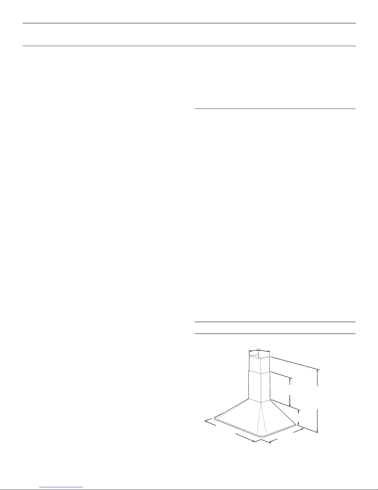
Product Dimensions
11³⁄₈"
(28.9 cm)
20⁷⁄₈"
(53.0 cm)
20³⁄₈"
(51.7 cm)
32³⁄₈" (82.2 cm) min.
46¹⁄₂" (118.0 cm) max.
*36" (91.4 cm) min.
*50⁷⁄₈" (129.2 cm) max.
10¹⁄₈"
(25.7 cm)
30" (76.2 cm)
or
36" (91.4 cm)
9³⁄₁₆"
(23.3 cm)
4
*For non-vented (recirculating) installations
†®TORX is a registered trademark of Textron Innovations Inc.
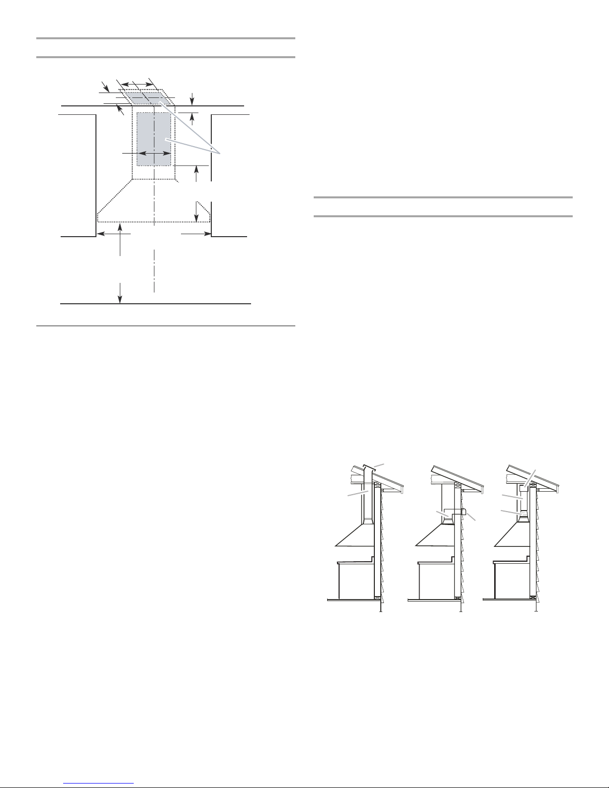
Installation Dimensions
10" (25.4 cm)
8¹⁄₂" (21.6 cm)
10"
(25.4 cm)
2" (5.1 cm) min.
9" (22.9 cm) min.*
Vent and power
entry location
17" (43.2 cm)*
supply cable
Cold weather installations
An additional back draft damper should be installed to minimize
backward cold air flow and a thermal break should be installed to
minimize conduction of outside temperatures as part of the vent
system. The damper should be on the cold air side of the thermal
break.
The break should be as close as possible to where the vent
system enters the heated portion of the house.
Makeup air
Local building codes may require the use of makeup air systems
when using ventilation systems greater than specified CFM of air
movement. The specified CFM varies from locale to locale.
Consult your HVAC professional for specific requirements in your
area.
Side
cabinet
30" (76.2 cm) min.
36" (91.4 cm) max.
bottom of canopy to
cooking surface
30" (76.2 cm)
or
36" (91.4 cm)
Centerline
Side
cabinet
*For non-vented (recirculating) installations
Venting Requirements
(vented models only)
■ Vent system must terminate to the outdoors, except for non-
vented (recirculating) installations.
■ Do not terminate the vent system in an attic or other enclosed
area.
■ Do not use 4" (10.2 cm) laundry-type wall cap.
■ Use metal vent only. Rigid metal vent is recommended.
Plastic or metal foil vent is not recommended.
■ The length of vent system and number of elbows should be
kept to a minimum to provide efficient performance.
For the most efficient and quiet operation:
■ Use no more than three 90° elbows.
■ Make sure there is a minimum of 24" (61 cm) of straight vent
between the elbows if more than 1 elbow is used.
■ Do not install 2 elbows together.
■ Use clamps to seal all joints in the vent system.
■ The vent system must have a damper. If the roof or wall cap
has a damper, do not use the damper supplied with the range
hood.
■ Use caulking to seal exterior wall or roof opening around the
cap.
■ The size of the vent should be uniform.
Venting Methods
This canopy hood is factory set for venting through the roof or
wall.
A 8" (20.0 cm) round vent system is needed for installation (not
included). The hood exhaust opening is 8" (20.0 cm) round.
NOTE: Flexible vent is not recommended. Flexible vent creates
back pressure and air turbulence that greatly reduce
performance.
Vent system can terminate either through the roof or wall. To vent
through a wall, a 90° elbow is needed.
Rear discharge
A 90° elbow may be installed immediately above the hood.
For non-vented (recirculating) installations
If it is not possible to vent cooking fumes and vapors to the
outside, the hood can be used in the non-vented (recirculating)
version, fitting an activated carbon filter and the deflector. Fumes
and vapors are recycled through the top grille.
Roof Venting Wall Venting Non-vented
(recirculating)
B
A. Roof cap
B. 8" (20.0 cm)
round vent
A
B
A. Wall cap
B. 8" (20.0 cm)
round vent
B
C
A
A. Deflector
B. 8" (20.0 cm)
round vent
C. Vent transition
adapter
A
5
 Loading...